EP0951148A2 - Synchronisiergerät und -verfahren für Direktsequenzspreizspektrumnachrichtenübertragung - Google Patents
Synchronisiergerät und -verfahren für Direktsequenzspreizspektrumnachrichtenübertragung Download PDFInfo
- Publication number
- EP0951148A2 EP0951148A2 EP99106145A EP99106145A EP0951148A2 EP 0951148 A2 EP0951148 A2 EP 0951148A2 EP 99106145 A EP99106145 A EP 99106145A EP 99106145 A EP99106145 A EP 99106145A EP 0951148 A2 EP0951148 A2 EP 0951148A2
- Authority
- EP
- European Patent Office
- Prior art keywords
- path
- received power
- phase
- variable
- section
- Prior art date
- Legal status (The legal status is an assumption and is not a legal conclusion. Google has not performed a legal analysis and makes no representation as to the accuracy of the status listed.)
- Withdrawn
Links
Images


Classifications
-
- H—ELECTRICITY
- H04—ELECTRIC COMMUNICATION TECHNIQUE
- H04B—TRANSMISSION
- H04B1/00—Details of transmission systems, not covered by a single one of groups H04B3/00 - H04B13/00; Details of transmission systems not characterised by the medium used for transmission
- H04B1/69—Spread spectrum techniques
- H04B1/707—Spread spectrum techniques using direct sequence modulation
- H04B1/7073—Synchronisation aspects
- H04B1/7075—Synchronisation aspects with code phase acquisition
- H04B1/70754—Setting of search window, i.e. range of code offsets to be searched
-
- H—ELECTRICITY
- H04—ELECTRIC COMMUNICATION TECHNIQUE
- H04B—TRANSMISSION
- H04B1/00—Details of transmission systems, not covered by a single one of groups H04B3/00 - H04B13/00; Details of transmission systems not characterised by the medium used for transmission
- H04B1/69—Spread spectrum techniques
- H04B1/707—Spread spectrum techniques using direct sequence modulation
- H04B1/7073—Synchronisation aspects
-
- H—ELECTRICITY
- H04—ELECTRIC COMMUNICATION TECHNIQUE
- H04B—TRANSMISSION
- H04B1/00—Details of transmission systems, not covered by a single one of groups H04B3/00 - H04B13/00; Details of transmission systems not characterised by the medium used for transmission
- H04B1/69—Spread spectrum techniques
- H04B1/707—Spread spectrum techniques using direct sequence modulation
- H04B1/7097—Interference-related aspects
- H04B1/711—Interference-related aspects the interference being multi-path interference
- H04B1/7115—Constructive combining of multi-path signals, i.e. RAKE receivers
- H04B1/7117—Selection, re-selection, allocation or re-allocation of paths to fingers, e.g. timing offset control of allocated fingers
Definitions
- the present invention relates to a synchronization processing apparatus in a receiver of a radio base station applying a CDMA (Code Division Multiple Access) system as a radio access system in a mobile communication system such as a car telephone and a portable telephone.
- CDMA Code Division Multiple Access
- a mobile station and a radio base station apparatus transmit and receive control data and user data via radio link.
- the mobile station transmits control data including a call request to a network side including the radio base station apparatus
- the mobile station generally uses a common physical channel that is used commonly by a plurality of users. Since such a channel becomes a random access channel by a plurality of users, it is necessary for the radio base station apparatus to perform receiving processing of burst signals by random access from a plurality of users individually.
- a mobile station acquires frame synchronization at a frame timing of a base station generally by receiving a perch channel signal that is a forward link signal transmitted from the base station.
- a radio base station In a CDMA system in which a channel over radio link is recognized by a spreading code, a radio base station usually performs RAKE receiving in which mobile station transmitted radio signals are received as a plurality of propagation paths to combine.
- RAKE receiving In Japanese Unexamined Patent Publication NO.8-181636, one of already-known configurations of a CDMA receiver for performing RAKE receiving comprises a synchronization processing section for performing search processing to detect a phase of a spreading code used in received spread data and a RAKE receiving section, based on the phases of spreading codes corresponding to a plurality of paths detected at the synchronization processing section, for despreading signals of a plurality of paths individually, correcting phases and performing a predetermined weighting to combine.
- a mobile station performs spreading by adjusting a spreading code phase (shift register initial value of a spreading code generator) to a frame timing synchronized with the base station to transmit a burst signal.
- a spreading code phase shift register initial value of a spreading code generator
- a mobile station transmits a burst signal so that a random access timing of the mobile station is synchronized with a frame timing of a base station in order to enable the base station to perform a path search in a range corresponding to a propagation delay time difference of communications between the base station and the mobile station to detect a path phase from the mobile station
- the base station it is possible for the base station to perform a phase adjusting (chip synchronization) of a spreading code to acquire frame synchronization.
- FIG.1 illustrates a block configuration of a conventional synchronization processing apparatus in a CDMA receiver.
- the principal part of the synchronization processing apparatus is composed of spreading code generating section 1 for generating a spreading code, matched filter 2 for performing correlation processing of received spread data with the spreading code output from spreading code generating section 1 while varying a phase to output the correlation value in a time sequence, delay profile data averaging section 3 for performing averaging processing on outputs from matched filter 2 over a predetermined interval to generate delay profile data, maximum selection path number setting section 4 for setting the upper limit of the number of paths which the synchronization processing apparatus can select, path selecting section 5 for selecting maximum N numbers of paths in order of the higher received power from paths with maximum received power corresponding to N numbers of paths assigned by maximum selection path number setting section 4 from data output from delay profile data averaging section 3, valid path threshold value setting section 6 for setting a threshold value to limit paths in obtaining candidate paths to be subjected to RAKE receiving, and valid path deciding section 7 for selecting only the path more than
- FIG.1 The operation of the synchronization processing apparatus in the conventional technique will be described next using FIG.1.
- the operation example described herein refers to the case of detecting as a maximum P-MAX numbers of path phases of paths whose received power levels exceed Pt (threshold value) in a range of search width S illustrated in FIG.3.
- Pt threshold value
- S search width
- a value of S is A ⁇ 2 samples in the case of operating the synchronization processing apparatus at an oversampling rate which is twice of a chip rate.
- a type of spreading code used in the random access channel is set at spreading code generating section 1
- maximum selection path number P-MAX is set at maximum selection path number setting section 4
- valid path threshold value Pt is set at valid path threshold value setting section 6.
- a maximum selection path number the number of a plurality of correlators comprised in the RAKE receiving section is usually set.
- a valid path threshold value a received power level which enables a decision to be performed as a path with received power level high enough to a noise level is set.
- Spreading code generating section 1 generates spreading codes in a time sequence to load at matched filter 2.
- a spreading code may be loaded at intervals of 62.5 ⁇ s using a matched filter of 512 (256 ⁇ 2) taps in the case of operating the synchronization processing apparatus by twice-oversampling. This operation is continued until the data necessary for averaging processing of delay profile data is acquired.
- Matched filter 2 outputs correlation values of spread data input to the matched filter with spreading codes loaded at the matched filter in a time sequence varying a phase of the spreading code.
- Delay profile data averaging section 3 performs averaging of delay profile data by integrating delay profile with an A-chip width output from matched filter 2 over a long enough interval. It is possible to reduce a noise component of the matched filter output data to improve a S/N ratio by this averaging processing.
- FIG.2 is a flowchart illustrating an operation example for the path phase detection at path selecting section 5 and valid path deciding section 7 in the synchronization processing apparatus of the conventional technique.
- S1 to S8 indicate an operation of path selecting section 5
- S9 to S14 indicate an operation of valid path deciding section 7.
- step (hereinafter abbreviated as S) variable n is initialized to 1, PD[0] is substituted for variable temp to shift to S2.
- step (S2) a comparison of maximum selection path number P-MAX with variable n is performed. Since P-MAX numbers of path phase detentions are finished when n>P-MAX, the processing shifts to S9, otherwise the processing shifts to S3.
- variable p is initialized to 1 to shift to S4.
- a comparison of variable p with search width S is performed.
- the processing shifts to S8 for the next path phase detection when p>S, otherwise the processing shifts to S5.
- S5 a comparison of PD[p] with temp is performed, and when PD[p]>temp and a value of PD[p] is not MARK, the processing shifts to S6 because it is anon-detected path phase, otherwise the processing shifts to S7.
- MARK is a mark for indicating a detected path phase.
- variable p is substituted for variable temp-p, and received power level PD[p]corresponding to this path phase p is substituted for variable temp, and 1 is incremented to a value of variable p to shift to S4.
- 1 is incremented to a value of variable p to shift to S4.
- path phase temp-p that is detected at the nth time is substituted for Phase[n]
- received power level PD[temp-p] is substituted for Level[n].
- MARK is substituted for PD[temp-p]
- further MARK is substituted for neighboring phases temp-p-1 and temp-p+1. It is because only a path phase having a distance more than one chip should be decided as a different independent path (in the case of twice-oversampling). 1 is incremented to a value of variable n for the next path phase detection to shift to S2.
- variable n is initialized by 1
- variable m is initialized by 0 to shift to S10.
- S10 a comparison of variable n with P-MAX is performed. Since P-MAX numbers of path phase detentions are finished when n>P-MAX, the processing shifts to S14, otherwise the processing shifts to S11.
- Phase[n] in order to make the nth path phase Phase[n] decided as valid the mth valid path phase, Phase[n] is substituted for Path[m]. 1 is incremented to variable m and variable n to shift to S10. In S13, since it is decided that the nth path phase is not a valid path phase, 1 is incremented to variable n to shift to S10. In S14, since valid path deciding section 7 finishes the decision of valid or invalid of path with respect to all P-MAX numbers of path phases detected by path selecting section 5, m numbers of path phases Path[0] to Path[m-1] are output to finish the path phase detection operation.
- the synchronization processing apparatus described in the above conventional technique operates to select paths whose received power levels are high using a predetermined maximum selection path number as a upper limit in a range of search width.
- the conventional apparatus since paths are selected based on received power levels, the conventional apparatus sometimes recognizes paths received from a plurality of mobile stations as paths received from the same one mobile station to select in the case where random accesses from a plurality of mobile stations (communication terminal apparatuses) occur at the almost same timing.
- FIG.3 is a diagram illustrating output data from a delay profile data averaging section at synchronization processing apparatus.
- received signals from mobile station MS1 are paths a, b and c
- received signals from mobile station MS2 are paths x, y and z.
- a difference between positions (path phase) observed in the delay profile of paths a, b, c and paths x, y, z corresponds to a difference between D1 that is a distance between mobile station MS1 and base station BTS and D2 that is a distance between mobile station MS2 and base station BTS.
- a mobile station estimates propagation loss ⁇ L between the mobile station and base station BTS by measuring received level of a perch channel at each mobile station to determine transmission power level of a bursts signal to be transmitted by random access channel. This method is called open-loop transmission power control.
- the synchronization processing apparatus in the conventional technique decides a received path from mobile station MS1 and a received path from mobile station MS2 as a multipath from the same mobile station. Therefore it has been a problem that the conventional synchronization processing apparatus sets path phases of paths x, a, b and c at a RAKE receiving section when selects four path phases, and combines a received signal from MS1 and a received signal from MS2. when the RAKE receiving section combines received signal form different mobile stations, it is not possible to correctly output a signal transmitted from any one of mobile stations.
- An object of the present invention is to provide a CDMA synchronization processing apparatus capable of detecting path phases for enabling a RAKE receiving section to as much as possible avoid combining received signals from different mobile stations.
- the apparatus detects, for example, in a range of search width S where a path phase of a received signal from a mobile station can be detected, path x that is a path with maximum received power, sets a search window of width W( ⁇ S) including the path x, and detects paths x, y and z to set at a RAKE receiving section in a range of W.
- the search window width W may be set in a range equal to or less than a spread width (delay spread) of multipath from the same mobile station (about two-digit ⁇ sec).
- FIG.4 is a block diagram illustrating a configuration of a CDMA receiver having a RAKE receiving function.
- the CDMA receiver which is placed in a base station to receive a reverse burst signal from a mobile station, is composed of radio section 101 connected to receiving antenna 100 for demodulating a spread signal from a received RF signal, A/D converter 102 for converting analog data output from radio section 101 into digital data, synchronization processing section 103 for detecting spreading code phases of a plurality of paths from the digital spread signals output from A/D converter 102, memory 104 for storing received spread data, RAKE receiving section 105 for performing RAKE receiving based on the spreading code phases detected by synchronization processing section 103, and channel decoder 107 for performing a frame deconstruction using output data from RAKE receiving section 105 based on a radio channel frame format to decode information from a mobile station.
- RAKE receiving section 105 is composed of spreading code generators 1052 each for generating spreading codes, correlators 1051 each for obtaining correlation of a spread signal read from memory 104 with the spreading code output from respective spreading code generator 1052 to output, phase correctors 1053 each for correcting the phase output from respective correlator 1051 to make every phase output from each correlator the same phase, weighting controllers 1054 each for performing a predetermined weighting on the output from respective phase correlator 1053, and combining section 106 for combining the outputs from weighting controllers 1054.
- the RAKE receiving section 105 thus has the RAKE receiving function for obtaining a correlation value individually with respect to a plurality of different paths assigned by synchronization processing section 103, correcting the phases, then performing a predetermined weighting to combine.
- FIG.5 is a block diagram illustrating a configuration of a synchronization processing apparatus according to the present invention used in the above synchronization processing section 103.
- the principal part of the synchronization processing apparatus is composed of spreading code generating section 201 for generating spreading codes, matched filter 202 for outputting correlation values of received spread data with the spreading code output from spreading code generating section 201 varying a phase of the spreading code in a time sequence, delay profile data averaging section 203 for performing averaging processing on outputs from matched filter 202 over a predetermined interval to generate delay profile data, search window position setting section 208 for detecting a path phase with maximum received power from the data output from delay profile data averaging section 203 , search window width setting section 209 for performing setting of a search window width determined according to a cell radius of a base station, search window control section 210 for setting a search window with the search window width instructed from search window width setting section 209 at a search window position instructed from search window position setting section 208, maximum selection path number
- the synchronization processing apparatus prior to initiate an operation of path phase detection, sets a type of spreading code used in the random access channel at spreading code generating section 201, sets maximum selection path number P-MAX at maximum selection path number setting section 204, sets valid path threshold value Pt at valid path threshold value setting section 206, and further sets search window width W and parameter Wb used to decide whether a search window is set to a path phase with maximum received power detected by search window position setting section 208 at search window width setting section 209.
- FIG.6 illustrates the relationship of parameter Wb to search window width W.
- spreading code generating section 201 and matched filter 202 and delay profile averaging section 203 are the same as the synchronization processing section illustrated in FIG.1.
- the description is given to the case of operating the synchronization processing apparatus according to the present invention by twice-oversampling.
- FIG.7 is a flowchart illustrating the operations for the path phase detection at search window position setting section 208, search window control section 210, path selecting section 205 and valid path deciding section 207 in the synchronization processing apparatus according to the first embodiment of the present invention.
- S101 to S106 indicate an operation of search window position setting section 208
- S107 indicates an operation of search window control section 210
- S108 to S114 indicate an operation of path selecting section 205
- S115 to S120 indicate an operation of valid path deciding section 207.
- variable p is initialized by 1, PD[0] is substituted for variable temp to shift to S102.
- S102 a comparison of variable p with search width S is performed. Since a detection of path phase with maximum received power is finished when p>S, the processing shifts to S106, otherwise the processing shifts to S103.
- S103 a comparison of PD[p] with temp is performed, and when PD[p]>temp, the processing shifts to S104, otherwise the processing shifts to S105.
- variable p is substituted for variable temp-p, and received power level PD[p] corresponding to this path phase p is substituted for variable temp, and 1 is incremented to a value of variable p to shift to S102.
- S105 1 is incremented to a value of variable p to shift to S102.
- phase temp-p of a path with detected maximum received power is substituted for Phase [1]
- received power level PD[temp-p] corresponding to path phase temp-p is substituted for Level[1].
- MARK is substituted for PD[temp-p]
- further MARK is substituted for neighboring phases temp-p-1 and temp-p+1 to shift to S107. It is thus possible to detect a position of a path that becomes a criterion of a search width. It is further possible to obtain a level of the path that becomes a criterion of a search width, thereby facilitating a control of search width and a determination of selected path number.
- W-Wb is substituted for variable Wf to set a search window according to search width W and Wb instructed from search window width setting section 209
- Phase[1]-Wf is substituted for variable Wstart that indicates a start position of the search window
- Phase]1]-Wb is substituted for variable Wend that indicates an end position of the search window to shift to S108.
- variable n is initialized to 2
- PD[0] is substituted for variable temp
- search window start position Wstart is substituted for variable p to shift to S109.
- a comparison of variable n with maximum selection path number P-MAX is performed. Since P-MAX numbers of path phase detentions are finished when n>P-MAX, the processing shifts to S115, otherwise the processing shifts to S110.
- a comparison of variable p with search window end position Wend is performed.
- the processing shifts to S114 when p>Wend, otherwise the processing shifts to S111.
- a comparison of PD(p] with variable temp is performed, and when PD[p]>temp and a value of PD[p] is not MARK, the processing shifts to S112 because it is a non-detected path phase, otherwise the processing shifts to S113.
- variable p is substituted for variable temp-p, and received power level PD[p]corresponding to this path phase p is substituted for variable temp, and 1 is incremented to a value of variable p to shift to S110.
- 1 is incremented to a value of variable p to shift to S110.
- path phase temp-p that is detected at the nth time is substituted for Phase [n]
- received power level PD[temp-p] corresponding to path phase temp-p is substituted for Level[n].
- MARK is substituted for PD[temp-p]
- further MARK is substituted for neighboring phases temp-p-1 and temp-p+1. 1 is incremented to a value of variable n for the next path phase detection to shift to S109.
- variable n is initialized by 1
- variable m is initialized by 0 to shift to S116.
- S116 a comparison of variable n with P-MAX is performed. Since P-MAX numbers of path phase detentions are finished when n>P-MAX, the processing shifts to S120, otherwise the processing shifts to S117. It is thus possible to properly set the maximum path number to be selected in a search width.
- Phase[n] in order to make the nth path phase Phase[n] decided as valid the mth valid path phase, Phase[n] is substituted for Path[m]. 1 is incremented to variable m and variable n to shift to S116. In S119, since it is decided that the nth path phase is not a valid path phase, 1 is incremented to variable n to shift to S116.
- the detected path phases are provided to spreading code generator 1053 at RAKE receiving section 105 from synchronization processing section 103.
- Spreading code generator 1053 performs a timing control using the input path phase as a phase of a spreading code, and according to the timing, outputs a spreading code to correlator 1051.
- Correlator 1051 performs correlation processing of a received signal with the spreading code.
- phase corrector 1053 corrects the output from correlator 1051 to make every phase output from each correlator the same phase.
- the corrected result is provided to weighting controller 1054.
- weighting controller 1054 At weighting controller 1054, a predetermined weighting is performed on the output from phase corrector 1053.
- the output from weighting controller 1054 is provided to combining section 106 for RAKE combining, and output to channel decoder 107.
- a search window position setting section for detecting a path phase having maximum received power in delay profile data and a search window control section for setting a search window in a search width in order to include the path with maximum received power detected by the search window position setting section are comprised, a path to be subjected to RAKE receiving is selected in a range of the search window to perform the path search. According to the above processing, it is possible to perform the path phase detection for as much as possible preventing received signals from different mobile stations from being combined even when random accesses from a plurality of different mobile stations occur at the almost same timing.
- the second embodiment of the present invention enables an apparatus according to the first embodiment to set a proper search window width based on the received power level of a path with maximum received power detected by the search window position setting section.
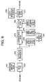
- FIG.8 is a block diagram illustrating a configuration of a synchronization processing apparatus according to the second embodiment of the present invention.
- the synchronization processing apparatus has a configuration where level measuring section 301 is installed in the synchronization processing apparatus illustrated in FIG.5.
- FIG.8 the same sections as in FIG.5 have the same symbols as FIG.5 to omit the detailed description.
- This synchronization processing apparatus prior to initiate an operation of path phase detection, sets a type of spreading code used in the random access channel at spreading code generating section 201, sets maximum selection path number P-MAX at maximum selection path number setting section 204, and sets valid path threshold value Pt at valid path threshold value setting section 206.
- spreading code generating section 201 matched filter 202 and delay profile averaging section 203 are the same as the synchronization processing apparatus illustrated in FIG.1.
- the description is given to the case of operating the synchronization processing apparatus according to the present invention by twice-oversampling.
- FIG.9 is a flowchart illustrating the operations for the path phase detection at search window position setting section 208, level measuring section 301, search window control section 210, path selecting section 205 and valid path deciding section 207 in the synchronization processing apparatus according to the second embodiment of the present invention.
- S201 to S206 indicate an operation of search window position setting section 208
- S207 indicates an operation of level measuring section 301
- S208 indicates an operation of search window control section 210
- S209 to S215 indicate an operation of path selecting section 205
- S216 to S221 indicate an operation of valid path deciding section 207.
- variable p is initialized by 1, PD[0] is substituted for variable temp to shift to S202.
- S202 a comparison of variable p with search width S is performed. Since a detection of path phase with maximum received power is finished when p>S, the processing shifts to S206, otherwise the processing shifts to S203.
- S203 a comparison of PD[p] with temp is performed, and when PD[p]>temp, the processing shifts to S204, otherwise the processing shifts to S205.
- variable p is substituted for variable temp-p, and received power level PD[p]corresponding to this path phase p is substituted for variable temp, and 1 is incremented to a value of variable p to shift to S202.
- 1 is incremented to a value of variable p to shift to S202.
- phase temp-p of a path with detected maximum received power is substituted for Phase [1]
- received power level PD[temp-p] corresponding to path phase temp-p is substituted for Level[1].
- MARK is substituted for PD[temp-p]
- further MARK is substituted for neighboring phases temp-p-1 and temp-p+1 to shift to S207.
- ⁇ /Level[1] is substituted for search window width w
- ⁇ ⁇ w is substituted for Wb to shift to S208.
- ⁇ is a coefficient to determine a proper search window width corresponding to a value of Level[1], and determined corresponding to a radio wave propagation environment around a place where a base station equipped with the synchronization processing apparatus of the present invention is placed.
- W ⁇ /Level[1] as a method for determining W.
- ⁇ is a coefficient for determining a position of Phase[1] in a search window, and adopts a value of 0 ⁇ 1. Setting ⁇ of less than 1 functions effectively in the case where received power of a delayed wave is higher than that of the direct wave.
- W-Wb is substituted for variable Wf to set a search window according to search width W and Wb instructed from search window width setting section 209
- Phase[1]-Wf is substituted for variable Wstart that indicates a start position of the search window
- Phase[1]-Wb is substituted for variable Wend that indicates an end position of the search window to shift to S209.
- variable n is initialized by 2
- PD[0] is substituted for variable temp
- search window start position Wstart is substituted for variable p to shift to S210.
- a comparison of variable n with maximum selection path number P-MAX is performed. Since P-MAX numbers of path phase detentions are finished when n>P-MAX, the processing shifts to S216, otherwise the processing shifts to S211.
- a comparison of variable p with search window end position Wend is performed.
- the processing shifts to S215 when p>Wend, otherwise the processing shifts to S212.
- a comparison of PD[p] with variable temp is performed, and when PD[p]>temp and a value of PD[p] is not MARK, the processing shifts to S213 because it is a non-detected path phase, otherwise the processing shifts to S214.
- variable p is substituted for variable temp-p, and received power level PD[p]corresponding to this path phase p is substituted for variable temp, and 1 is incremented to a value of variable p to shift to S211.
- 1 is incremented to a value of variable p to shift to S211.
- path phase temp-p that is detected at the nth time is substituted for Phase [n]
- received power level PD[temp-p] corresponding to path phase temp-p is substituted for Level[n].
- MARK is substituted for PD[temp-p]
- further MARK is substituted for neighboring phases temp-p-1 and temp-p+1. 1 is incremented to a value of variable n for the next path phase detection to shift to S210.
- variable n is initialized by 1
- variable m is initialized by 0 to shift to S217.
- S217 a comparison of variable n with P-MAX is performed. Since P-MAX numbers of path phase detentions are finished when n>P-MAX, the processing shifts to S221, otherwise the processing shifts to S218.
- Phase[n] in order to make the nth path phase Phase[n] decided as valid the mth valid path phase, Phase[n] is substituted for Path[m]. 1 is incremented to variable m and variable n to shift to S217. In S220, since it is decided that the nth path phase is not a valid path phase, 1 is incremented to variable n to shift to S217.
- the detected path phases are provided to RAKE receiving section 105 and used in performing the RAKE combining processing.
- the method for performing the RAKE combining processing using these path phases is the same as the first embodiment.
- level measuring section 301 determines a proper search window width W based on received power level Level[1] of a path with maximum received power detected by search window position setting section 208.
- Level[1] is high enough, since it is possible to good receiving characteristics by combining even a small number of paths, the possibility that paths from different mobile stations are included in a search window width is further reduced by setting the search window width narrower.
- Level[1] is low, in order to improve the receiving characteristics, it is possible to perform path phase detection by setting the search window width wider to select an enough number of paths that are effective for RAKE receiving.
- the third embodiment of the present invention enables an apparatus according to the second embodiment to set a proper maximum selection path number based on the received power level of a path with maximum received power detected by the search window position setting section.
- Level measuring section 301 determines the maximum selection path number corresponding to the received power level of a path with maximum power level, and a maximum selection path number setting section is further comprised to instruct the maximum selection path number to path selecting section 205.
- the operation in this synchronization processing apparatus will be described using FIG.10.
- the synchronization processing apparatus prior to initiate an operation of path phase detection, sets a type of spreading code used in the random access channel at spreading code generating section 201, and sets valid path threshold value Pt at valid path threshold value setting section 206.
- spreading code generating section 201 matched filter 202 and delay profile averaging section 203 are the same as the synchronization processing apparatus illustrated in FIG.1.
- the description is given to the case of operating the synchronization processing apparatus according to the present invention by twice-oversampling.
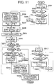
- FIG.11 is a flowchart illustrating the operations for the path phase detection at search window position setting section 208, level measuring section 301, search window control section 210, path selecting section 205 and valid path deciding section 207 in the synchronization processing apparatus according to the third embodiment of the present invention.
- S301 to S306 indicate an operation of search window position setting section 208
- S307 and S308 indicate an operation of level measuring section 301
- S308 indicates an operation of search window control section 210
- S310 to S316 indicate an operation of path selecting section 205
- S317 to S322 indicate an operation of valid path deciding section 207.
- variable p is initialized by 1, PD[0] is substituted for variable temp to shift to S302.
- a comparison of variable p with search width S is performed. Since a detection of path phase with maximum received power is finished when p>S, the processing shifts to S306, otherwise the processing shifts to S303.
- S303 a comparison of PD[p] with temp is performed, and when PD[p]>temp, the processing shifts to S304, otherwise the processing shifts to S305.
- variable p is substituted for variable temp-p, and received power level PD[p]corresponding to this path phase p is substituted for variable temp, and 1 is incremented to a value of variable p to shift to S302.
- S305 1 is incremented to a value of variable p to shift to S302.
- phase temp-p of a path with detected maximum received power is substituted for Phase [1]
- received power level PD[temp-p] corresponding to path phase temp-p is substituted for Level[1].
- MARK is substituted for PD[temp-p]
- further MARK is substituted for neighboring phases temp-p-1 and temp-p+1 to shift to S307.
- W-Wb is substituted for variable Wf to set a search window according to search width W and Wb instructed from search window width setting section 209
- Phase[1]-Wf is substituted for variable Wstart that indicates a start position of the search window
- Phase[1]-Wb is substituted for variable Wend that indicates an end position of the search window to shift to S309.
- a value of maximum selection path number P-MAX is determined based on a value of Level[1] to shift to S310.
- table(Level[1]) indicates that the maximum selection path number is obtained from a value of Level[1] using a conversion table.
- the maximum selection path number is decreased when the value of Level[1] is high, while the maximum selection path number is increased when the value of Level[1] is low.
- variable n is initialized by 2
- PD[0] is substituted for variable temp
- search window start position Wstart is substituted for variable p to shift to S311.
- a comparison of variable n with maximum selection path number P-MAX is performed. Since P-MAX numbers of path phase detentions are finished when n>P-MAX, the processing shifts to S317, otherwise the processing shifts to S312.
- variable p is substituted for variable temp-p, and received power level PD[p]corresponding to this path phase p is substituted for variable temp, and 1 is incremented to a value of variable p to shift to S312.
- 1 is incremented to a value of variable p to shift to S312.
- path phase temp-p that is detected at the nth time is substituted for Phase [n]
- received power level PD[temp-p] corresponding to path phase temp-p is substituted for Level[n].
- MARK is substituted for PD[temp-p]
- further MARK is substituted for neighboring phases temp-p-1 and temp-p+1. 1 is incremented to a value of variable n for the next path phase detection to shift to S311.
- variable n is initialized by 1
- variable m is initialized by 0 to shift to S318.
- Phase[n] decided as valid the mth valid path phase
- Phase[n] is substituted for Path[m]. 1 is incremented to variable m and variable n to shift to S318.
- S321 since it is decided that the nth path phase is not a valid path phase, 1 is incremented to variable n to shift to S318.
- the detected path phases are provided to RAKE receiving section 105 and used in performing the RAKE combining processing.
- the method for performing the RAKE combining processing using these path phases is the same as the first embodiment.
- level measuring section 301 determines a proper maximum selection path number P-MAX based on received power level Level[1] of a path with maximum received power detected by search window position setting section 208.
- Level[1] is high enough, since it is possible to good receiving characteristics by combining even a small number of paths, the possibility that paths from different mobile stations are included in a search window width is further reduced by setting maximum selection path number smaller.
- Level[1] is low, in order to improve the receiving characteristics, it is possible to perform path phase detection by setting maximum selection path number P-MAX larger to select an enough number of paths that are effective for RAKE receiving.
- the fourth embodiment of the present invention enables an apparatus according to the first embodiment to detect minimum value Lmin from delay profile data PD[P] to PD[S] subjected to the averaging processing and output from the delay profile data averaging section so as to set a threshold value to extract a path to be subjected to RAKE receiving corresponding to a value of Lmin, and comprises minimum value detecting section 401 in the configuration described in the first embodiment.
- This synchronization processing apparatus prior to initiate an operation of path phase detection, sets a type of spreading code used in the random access channel at spreading code generating section 201, sets maximum selection path number P-MAX at maximum selection path number setting section 204, sets threshold value Pt that is a relative value determined corresponding to minimum value min detected by minimum value detecting section 401 at valid path threshold value setting section 206, and further sets search window width W and parameter Wb used to decide whether a search window is set to a path phase with maximum received power detected by search window position setting section 208 at search window width setting section 209.
- spreading code generating section 201 matched filter 202 and delay profile averaging section 203 are the same as the synchronization processing apparatus illustrated in FIG.1.
- the description is given to the case of operating the synchronization processing apparatus according to the present invention by twice-oversampling.
- FIG.13 is a flowchart illustrating the operations for the path phase detection at search window position setting section 208, minimum value detecting section 401, search window control section 210, path selecting section 205 and valid path deciding section 207 in the synchronization processing apparatus according to the fourth embodiment of the present invention.
- S401 to S408 indicate operations of search window position setting section 208 and minimum value detecting section 401
- S409 indicates an operation of search window control section 210
- S410 to S416 indicate an operation of path selecting section 205
- S417 to S422 indicate an operation of valid path deciding section 207.
- variable p is initialized by 1, PD[0] is substituted for variable temp, and PD[0] is substituted for variable min to shift to S402.
- S402 a comparison of variable p with search width S is performed. Since a detection of path phase with maximum received power is finished when p>S, the processing shifts to S408, otherwise the processing shifts to S403.
- a comparison of PD[p] with variable min is performed, and when PD[p] ⁇ min, the processing shifts to S406, otherwise the processing shifts to S407.
- PD[p] is substituted for variable min, and 1 is incremented to a value of variable p to shift to S402.
- S407 1 is incremented to a value of variable p to shift to S402.
- phase temp-p of a path with detected maximum received power is substituted for Phase [1]
- received power level PD[temp-p] corresponding to path phase temp-p is substituted for Level[1].
- MARK is substituted for PD[temp-p]
- further MARK is substituted for neighboring phases temp-p-1 and temp-p+1 to shift to S409.
- W-Wb is substituted for variable Wf to set a search window according to search width W and Wb instructed from search window width setting section 209
- Phase[1]-Wf is substituted for variable Wstart that indicates a start position of the search window
- Phase[1]-Wb is substituted for variable Wend that indicates an end position of the search window to shift to S410.
- variable n is initialized by 2
- PD[0] is substituted for variable temp
- search window start position Wstart is substituted for variable p to shift to S411.
- a comparison of variable n with maximum selection path number P-MAX is performed. Since P-MAX numbers of path phase detentions are finished when n>P-MAX, the processing shifts to S417, otherwise the processing shifts to S412.
- a comparison of variable p with search window end position Wend is performed.
- the processing shifts to S416 when p>Wend, otherwise the processing shifts to S413.
- a comparison of PD[p] with variable temp is performed, and when PD[p]>temp and a value of PD[p] is not MARK, the processing shifts to S414 because it is a non-detected path phase, otherwise the processing shifts to S415.
- variable p is substituted for variable temp-p, and received power level PD[p]corresponding to this path phase p is substituted for variable temp, and 1 is incremented to a value of variable p to shift to S412.
- 1 is incremented to a value of variable p to shift to S412.
- path phase temp-p that is detected at the nth time is substituted for Phase [n]
- received power level PD[temp-p] corresponding to path phase temp-p is substituted for Level[n].
- MARK is substituted for PD[temp-p]
- further MARK is substituted for neighboring phases temp-p-1 and temp-p+1. 1 is incremented to a value of variable n for the next path phase detection to shift to S412.
- variable n is initialized by 1
- variable m is initialized by 0 to shift to S418.
- Phase[n] in order to make the nth path phase Phase[n] decided as valid the mth valid path phase, Phase[n] is substituted for Path[m]. 1 is incremented to variable m and variable n to shift to S418. In S421, since it is decided that the nth path phase is not a valid path phase, 1 is incremented to variable n to shift to S418.
- the detected path phases are provided to RAKE receiving section 105 and used in performing the RAKE combining processing.
- the method for performing the RAKE combining processing is the same as the first embodiment.
- minimum value detecting section 401 detects the minimum received power level min using data output from delay profile data averaging section 203, and assuming min as an approximate value of noise, sets min+Pt that is a sum of min and relative threshold value Pt predetermined to min as a received power threshold value to select a path to be subjected to RAKE receiving. This processing thus makes it possible to set a proper valid path threshold value depending on fluctuations of noise.
- radio section 102 generally controls an amplitude gain of a received RF signal to obtain a proper amplitude of the signal corresponding to a dynamic range of A/D converter 103. Therefore, an amplitude of a spread signal input to the synchronization processing apparatus is affected by the above control, and the noise level contained in the spread signal fluctuates. The noise level also fluctuates in an averaging interval of the averaging processing in the delay profile averaging section of the present invention.
- the present invention is not limited to the above described embodiments, and various variations and modifications may be possible without departing from the scope of the present invention.
- the present invention is applicable to all apparatuses that need to obtain a path phase of a received signal exactly without being affected by interference waves.
- a search window of width W (W ⁇ S) to include a path phase with maximum received power is set in a search width S that is a range where path search should be performed in order to limit the selection range of paths to be subjected to RAKE receiving within the above search window. It is thus possible to as much as possible avoid combining a plurality of paths from different mobile stations to perform RAKE receiving.
Landscapes
- Engineering & Computer Science (AREA)
- Computer Networks & Wireless Communication (AREA)
- Signal Processing (AREA)
- Synchronisation In Digital Transmission Systems (AREA)
- Mobile Radio Communication Systems (AREA)
Applications Claiming Priority (2)
| Application Number | Priority Date | Filing Date | Title |
|---|---|---|---|
| JP10314098 | 1998-04-14 | ||
| JP10103140A JPH11298401A (ja) | 1998-04-14 | 1998-04-14 | 同期処理装置及び同期処理方法 |
Publications (1)
| Publication Number | Publication Date |
|---|---|
| EP0951148A2 true EP0951148A2 (de) | 1999-10-20 |
Family
ID=14346231
Family Applications (1)
| Application Number | Title | Priority Date | Filing Date |
|---|---|---|---|
| EP99106145A Withdrawn EP0951148A2 (de) | 1998-04-14 | 1999-04-07 | Synchronisiergerät und -verfahren für Direktsequenzspreizspektrumnachrichtenübertragung |
Country Status (3)
| Country | Link |
|---|---|
| EP (1) | EP0951148A2 (de) |
| JP (1) | JPH11298401A (de) |
| CN (1) | CN1232326A (de) |
Cited By (17)
| Publication number | Priority date | Publication date | Assignee | Title |
|---|---|---|---|---|
| GB2356776A (en) * | 1999-11-26 | 2001-05-30 | Roke Manor Research | Synchronisation in mobile telecommunication systems |
| WO2001054294A1 (en) * | 2000-01-19 | 2001-07-26 | Mitsubishi Denki Kabushiki Kaisha | Spread spectrum receiver and spread spectrum receiving method |
| WO2002005446A1 (en) * | 2000-07-07 | 2002-01-17 | Telefonaktiebolaget Lm Ericsson (Publ) | Rake receiver and method related to a rake receiver |
| GB2368236A (en) * | 2000-10-16 | 2002-04-24 | Ubinetics Ltd | Channel equalisation for countering multi path propagation |
| EP1251642A1 (de) * | 2001-04-19 | 2002-10-23 | Telefonaktiebolaget Lm Ericsson | Eine CDMA Mobilstation mit Leistungsersparung unter Verwendung eines anpassbaren Korrelationsfensters in der Pfadsuche |
| WO2002087100A1 (en) * | 2001-04-19 | 2002-10-31 | Telefonaktiebolaget Lm Ericsson (Publ) | A cdma mobile station with power saving using adaptive correlation window in path search |
| EP1241817A4 (de) * | 2000-10-06 | 2003-01-22 | Yozan Inc | Empfänger |
| EP1126627A3 (de) * | 2000-02-14 | 2003-03-05 | Nec Corporation | Pfadsuchverfahren für Bandspreizkommunikationssysteme und Empfänger zur Anwendung dieses Verfahrens |
| WO2003075480A1 (en) * | 2002-03-04 | 2003-09-12 | Nokia Corporation | Receiving spread spectrum signal in radio system |
| DE10260653A1 (de) * | 2002-12-23 | 2004-07-08 | Infineon Technologies Ag | Mobilfunkempfänger-Architektur und Verfahren zum Synchronisieren von Hardware-Blöcken eines Mobilfunkempfängers |
| EP1482649A1 (de) * | 2003-05-27 | 2004-12-01 | Telefonaktiebolaget LM Ericsson (publ) | Positionierung eines Recherchegleitfensters zum Mehrwegsignalenempfäng |
| WO2004107599A1 (en) * | 2003-05-27 | 2004-12-09 | Telefonaktiebolaget L M Ericsson (Publ) | Positioning a multipath search window |
| EP1263149A3 (de) * | 2001-05-31 | 2005-01-26 | Fujitsu Limited | CDMA-Empfänger |
| US6934553B2 (en) | 2001-09-12 | 2005-08-23 | Fujitsu Limited | Receiving unit, receiving method and semiconductor device |
| EP1729426A3 (de) * | 2001-02-14 | 2007-07-25 | NEC Corporation | Mobilkommunikationssystem, Basisstation und Kommunikationssteuerverfahren |
| EP2649835A4 (de) * | 2010-12-07 | 2016-12-21 | ERICSSON TELEFON AB L M (publ) | Anordnung und verfahren für eine funkbasisstation und funkeinheiten |
| WO2019201285A1 (en) * | 2018-04-18 | 2019-10-24 | Huawei Technologies Co., Ltd. | Apparatus and receiver for performing synchronization in analog spread spectrum systems |
Families Citing this family (11)
| Publication number | Priority date | Publication date | Assignee | Title |
|---|---|---|---|---|
| JP3322240B2 (ja) | 1999-05-10 | 2002-09-09 | 日本電気株式会社 | Cdma受信機 |
| US6801564B2 (en) * | 2000-02-23 | 2004-10-05 | Ipr Licensing, Inc. | Reverse link correlation filter in wireless communication systems |
| JP3476009B2 (ja) | 2000-10-11 | 2003-12-10 | 日本電気株式会社 | Cdma通信システムにおける移動局及びそのフィンガー割り当て方法 |
| JP2002335190A (ja) * | 2001-05-08 | 2002-11-22 | Nec Corp | Cdma受信機及びパス捕捉方法 |
| JP3719175B2 (ja) | 2001-08-22 | 2005-11-24 | 日本電気株式会社 | 同期追跡回路 |
| JP3753637B2 (ja) | 2001-08-30 | 2006-03-08 | Necマイクロシステム株式会社 | Cdma受信装置におけるパス検出方法及びその装置並びに制御プログラムを記録した記録媒体 |
| JP4361086B2 (ja) * | 2004-03-12 | 2009-11-11 | 三菱電機株式会社 | パスサーチ装置、パスサーチ方法およびパスサーチ用プログラム |
| JP4569328B2 (ja) * | 2004-03-18 | 2010-10-27 | パナソニック株式会社 | 無線通信装置および経路探索方法 |
| FR2943192B1 (fr) * | 2009-03-13 | 2011-06-03 | St Wireless Sa | Procede d'affectation d'un doigt (finger) pour un recepteur de type rateau (rake) en mode de veille,et dispositif pour la mise en oeuvre du procede |
| KR20150075483A (ko) * | 2013-12-26 | 2015-07-06 | 엘에스산전 주식회사 | 열차 시스템에서 불연속정보 처리장치 |
| CN105466803A (zh) * | 2015-11-20 | 2016-04-06 | 江苏焦点农业科技有限公司 | 一种快速、高效、稳定水稻淀粉膨胀势和可溶性微量测定方法 |
-
1998
- 1998-04-14 JP JP10103140A patent/JPH11298401A/ja active Pending
-
1999
- 1999-04-07 EP EP99106145A patent/EP0951148A2/de not_active Withdrawn
- 1999-04-14 CN CN99105217A patent/CN1232326A/zh active Pending
Cited By (24)
| Publication number | Priority date | Publication date | Assignee | Title |
|---|---|---|---|---|
| GB2356776A (en) * | 1999-11-26 | 2001-05-30 | Roke Manor Research | Synchronisation in mobile telecommunication systems |
| WO2001054294A1 (en) * | 2000-01-19 | 2001-07-26 | Mitsubishi Denki Kabushiki Kaisha | Spread spectrum receiver and spread spectrum receiving method |
| US6912243B1 (en) | 2000-01-19 | 2005-06-28 | Mitsubishi Denki Kabushiki Kaisha | Spread spectrum receiver and spread spectrum receiving method |
| US7072383B2 (en) | 2000-02-14 | 2006-07-04 | Nec Electronics Corporation | Path search method of spread spectrum communication system and receiver using the method |
| EP1126627A3 (de) * | 2000-02-14 | 2003-03-05 | Nec Corporation | Pfadsuchverfahren für Bandspreizkommunikationssysteme und Empfänger zur Anwendung dieses Verfahrens |
| WO2002005446A1 (en) * | 2000-07-07 | 2002-01-17 | Telefonaktiebolaget Lm Ericsson (Publ) | Rake receiver and method related to a rake receiver |
| EP1241817A4 (de) * | 2000-10-06 | 2003-01-22 | Yozan Inc | Empfänger |
| GB2368236B (en) * | 2000-10-16 | 2004-09-22 | Ubinetics Ltd | Broadcasting path difference limit information |
| GB2368236A (en) * | 2000-10-16 | 2002-04-24 | Ubinetics Ltd | Channel equalisation for countering multi path propagation |
| US7738889B2 (en) | 2001-02-14 | 2010-06-15 | Nec Corporation | Mobile communication system, base station, and communication control method |
| EP1729426A3 (de) * | 2001-02-14 | 2007-07-25 | NEC Corporation | Mobilkommunikationssystem, Basisstation und Kommunikationssteuerverfahren |
| WO2002087100A1 (en) * | 2001-04-19 | 2002-10-31 | Telefonaktiebolaget Lm Ericsson (Publ) | A cdma mobile station with power saving using adaptive correlation window in path search |
| EP1251642A1 (de) * | 2001-04-19 | 2002-10-23 | Telefonaktiebolaget Lm Ericsson | Eine CDMA Mobilstation mit Leistungsersparung unter Verwendung eines anpassbaren Korrelationsfensters in der Pfadsuche |
| EP1263149A3 (de) * | 2001-05-31 | 2005-01-26 | Fujitsu Limited | CDMA-Empfänger |
| US6934553B2 (en) | 2001-09-12 | 2005-08-23 | Fujitsu Limited | Receiving unit, receiving method and semiconductor device |
| WO2003075480A1 (en) * | 2002-03-04 | 2003-09-12 | Nokia Corporation | Receiving spread spectrum signal in radio system |
| DE10260653A1 (de) * | 2002-12-23 | 2004-07-08 | Infineon Technologies Ag | Mobilfunkempfänger-Architektur und Verfahren zum Synchronisieren von Hardware-Blöcken eines Mobilfunkempfängers |
| DE10260653B4 (de) * | 2002-12-23 | 2010-12-09 | Infineon Technologies Ag | Mobilfunkempfänger-Architektur und Verfahren zum Synchronisieren von Hardware-Blöcken eines Mobilfunkempfängers |
| WO2004107599A1 (en) * | 2003-05-27 | 2004-12-09 | Telefonaktiebolaget L M Ericsson (Publ) | Positioning a multipath search window |
| EP1482649A1 (de) * | 2003-05-27 | 2004-12-01 | Telefonaktiebolaget LM Ericsson (publ) | Positionierung eines Recherchegleitfensters zum Mehrwegsignalenempfäng |
| US7826515B2 (en) | 2003-05-27 | 2010-11-02 | Telefonaktiebolaget L M Ericsson (Publ) | Positioning a multipath search window |
| EP2649835A4 (de) * | 2010-12-07 | 2016-12-21 | ERICSSON TELEFON AB L M (publ) | Anordnung und verfahren für eine funkbasisstation und funkeinheiten |
| WO2019201285A1 (en) * | 2018-04-18 | 2019-10-24 | Huawei Technologies Co., Ltd. | Apparatus and receiver for performing synchronization in analog spread spectrum systems |
| US10879952B2 (en) | 2018-04-18 | 2020-12-29 | Huawei Technologies Co., Ltd. | Apparatus and receiver for performing synchronization in analog spread spectrum systems |
Also Published As
| Publication number | Publication date |
|---|---|
| CN1232326A (zh) | 1999-10-20 |
| JPH11298401A (ja) | 1999-10-29 |
Similar Documents
| Publication | Publication Date | Title |
|---|---|---|
| EP0951148A2 (de) | Synchronisiergerät und -verfahren für Direktsequenzspreizspektrumnachrichtenübertragung | |
| CA2409962C (en) | Calibration system of array antenna receiving apparatus | |
| AU756272B2 (en) | Cellular system, mobile portable apparatus, base station apparatus, optimum path detecting method, and apparatus thereof | |
| EP1052783B1 (de) | CDMA-Empfänger mit kontrollierbarem Suchgebiet und Verfahren zur Kontrolle desselben | |
| JP4195901B2 (ja) | ワイヤレス通信システムにおける初期セルサーチ | |
| US5966402A (en) | Method and apparatus for detecting pilot signals and subscriber | |
| EP1374431B1 (de) | Verfahren und vorrichtung zur schnellen w-cdma erfassung | |
| JP3369513B2 (ja) | 通信端末装置及び無線受信方法 | |
| EP1187576A1 (de) | Beschleunigte wahl einer basisstation in einem drahtlosen kommunikationssystem | |
| EP1499032A1 (de) | Sir-messungseinrichtung und verfahren | |
| KR100414316B1 (ko) | 패스 검색 방법 및 장치 | |
| EP1237314A1 (de) | Verfahren und kontrolle zur zellensuche | |
| EP1571756B1 (de) | Mehrstrahlantennenempfangseinrichtung und mehrstrahlempfangsverfahren | |
| JP2003347968A (ja) | パス位置検出方法およびcdma受信装置 | |
| US20040259517A1 (en) | Apparatus and method for reception | |
| WO2003063388A1 (en) | Apparatus and method for controlling transmission power in cell search | |
| US20050083898A1 (en) | Communication control apparatus, and CDMA communication system using the same | |
| EP1564902A1 (de) | Vorrichtung und verfahren zur synchronisationsbehandlung | |
| US20060246928A1 (en) | Synchronization processing apparatus and synchronization processing method | |
| WO2001015353A1 (en) | A method of measuring a characteristic of a radio signal and apparatus therefor |
Legal Events
| Date | Code | Title | Description |
|---|---|---|---|
| PUAI | Public reference made under article 153(3) epc to a published international application that has entered the european phase |
Free format text: ORIGINAL CODE: 0009012 |
|
| AK | Designated contracting states |
Kind code of ref document: A2 Designated state(s): AT BE CH CY DE DK ES FI FR GB GR IE IT LI LU MC NL PT SE |
|
| AX | Request for extension of the european patent |
Free format text: AL;LT;LV;MK;RO;SI |
|
| STAA | Information on the status of an ep patent application or granted ep patent |
Free format text: STATUS: THE APPLICATION HAS BEEN WITHDRAWN |
|
| 18W | Application withdrawn |
Effective date: 20030617 |