EP0951079B1 - Dry cell and method of manufacturing outer can therefor - Google Patents
Dry cell and method of manufacturing outer can therefor Download PDFInfo
- Publication number
- EP0951079B1 EP0951079B1 EP97939161A EP97939161A EP0951079B1 EP 0951079 B1 EP0951079 B1 EP 0951079B1 EP 97939161 A EP97939161 A EP 97939161A EP 97939161 A EP97939161 A EP 97939161A EP 0951079 B1 EP0951079 B1 EP 0951079B1
- Authority
- EP
- European Patent Office
- Prior art keywords
- metal jacket
- blank
- notches
- dry cell
- cell
- Prior art date
- Legal status (The legal status is an assumption and is not a legal conclusion. Google has not performed a legal analysis and makes no representation as to the accuracy of the status listed.)
- Expired - Lifetime
Links
Images


Classifications
-
- H—ELECTRICITY
- H01—ELECTRIC ELEMENTS
- H01M—PROCESSES OR MEANS, e.g. BATTERIES, FOR THE DIRECT CONVERSION OF CHEMICAL ENERGY INTO ELECTRICAL ENERGY
- H01M50/00—Constructional details or processes of manufacture of the non-active parts of electrochemical cells other than fuel cells, e.g. hybrid cells
- H01M50/10—Primary casings, jackets or wrappings of a single cell or a single battery
- H01M50/172—Arrangements of electric connectors penetrating the casing
- H01M50/174—Arrangements of electric connectors penetrating the casing adapted for the shape of the cells
- H01M50/182—Arrangements of electric connectors penetrating the casing adapted for the shape of the cells for cells with a collector centrally disposed in the active mass, e.g. Leclanché cells
-
- H—ELECTRICITY
- H01—ELECTRIC ELEMENTS
- H01M—PROCESSES OR MEANS, e.g. BATTERIES, FOR THE DIRECT CONVERSION OF CHEMICAL ENERGY INTO ELECTRICAL ENERGY
- H01M50/00—Constructional details or processes of manufacture of the non-active parts of electrochemical cells other than fuel cells, e.g. hybrid cells
- H01M50/10—Primary casings, jackets or wrappings of a single cell or a single battery
- H01M50/116—Primary casings, jackets or wrappings of a single cell or a single battery characterised by the material
- H01M50/117—Inorganic material
- H01M50/119—Metals
-
- H—ELECTRICITY
- H01—ELECTRIC ELEMENTS
- H01M—PROCESSES OR MEANS, e.g. BATTERIES, FOR THE DIRECT CONVERSION OF CHEMICAL ENERGY INTO ELECTRICAL ENERGY
- H01M50/00—Constructional details or processes of manufacture of the non-active parts of electrochemical cells other than fuel cells, e.g. hybrid cells
- H01M50/10—Primary casings, jackets or wrappings of a single cell or a single battery
- H01M50/116—Primary casings, jackets or wrappings of a single cell or a single battery characterised by the material
- H01M50/124—Primary casings, jackets or wrappings of a single cell or a single battery characterised by the material having a layered structure
-
- H—ELECTRICITY
- H01—ELECTRIC ELEMENTS
- H01M—PROCESSES OR MEANS, e.g. BATTERIES, FOR THE DIRECT CONVERSION OF CHEMICAL ENERGY INTO ELECTRICAL ENERGY
- H01M50/00—Constructional details or processes of manufacture of the non-active parts of electrochemical cells other than fuel cells, e.g. hybrid cells
- H01M50/10—Primary casings, jackets or wrappings of a single cell or a single battery
- H01M50/131—Primary casings, jackets or wrappings of a single cell or a single battery characterised by physical properties, e.g. gas-permeability or size
- H01M50/133—Thickness
-
- H—ELECTRICITY
- H01—ELECTRIC ELEMENTS
- H01M—PROCESSES OR MEANS, e.g. BATTERIES, FOR THE DIRECT CONVERSION OF CHEMICAL ENERGY INTO ELECTRICAL ENERGY
- H01M6/00—Primary cells; Manufacture thereof
- H01M6/04—Cells with aqueous electrolyte
- H01M6/06—Dry cells, i.e. cells wherein the electrolyte is rendered non-fluid
-
- Y—GENERAL TAGGING OF NEW TECHNOLOGICAL DEVELOPMENTS; GENERAL TAGGING OF CROSS-SECTIONAL TECHNOLOGIES SPANNING OVER SEVERAL SECTIONS OF THE IPC; TECHNICAL SUBJECTS COVERED BY FORMER USPC CROSS-REFERENCE ART COLLECTIONS [XRACs] AND DIGESTS
- Y02—TECHNOLOGIES OR APPLICATIONS FOR MITIGATION OR ADAPTATION AGAINST CLIMATE CHANGE
- Y02P—CLIMATE CHANGE MITIGATION TECHNOLOGIES IN THE PRODUCTION OR PROCESSING OF GOODS
- Y02P70/00—Climate change mitigation technologies in the production process for final industrial or consumer products
- Y02P70/50—Manufacturing or production processes characterised by the final manufactured product
-
- Y—GENERAL TAGGING OF NEW TECHNOLOGICAL DEVELOPMENTS; GENERAL TAGGING OF CROSS-SECTIONAL TECHNOLOGIES SPANNING OVER SEVERAL SECTIONS OF THE IPC; TECHNICAL SUBJECTS COVERED BY FORMER USPC CROSS-REFERENCE ART COLLECTIONS [XRACs] AND DIGESTS
- Y10—TECHNICAL SUBJECTS COVERED BY FORMER USPC
- Y10T—TECHNICAL SUBJECTS COVERED BY FORMER US CLASSIFICATION
- Y10T29/00—Metal working
- Y10T29/49—Method of mechanical manufacture
- Y10T29/49002—Electrical device making
- Y10T29/49108—Electric battery cell making
- Y10T29/4911—Electric battery cell making including sealing
Definitions
- the present invention relates to a dry cell which is relatively small in size and has a cylindrical appearance and to a method of manufacturing an outer metal jacket of the dry cell.
- Such a metallic outer jacket of a dry cell (referred to as simply an outer metal jacket) is commonly fabricated in such a producing process as shown in Fig. 6.
- the procedure starts with cutting a hoop material of about 0.2mm thickness made of tin-plated steel into rectangular base sheets 1 of predetermined dimensions, for example 785 mm wide and 850 mm long, as shown in Fig. 6(a). This is followed by slitting and trimming two edges of about 2 mm width along both opposing sides of the base sheet 1.
- slits are formed which are equally spaced and parallel to the sides of the base sheet 1 as denoted by the two-dot chain lines in Fig. 6(b).
- the base sheet 1 is then cut along these slits into a group of intermediate strips 3 as shown in Fig. 6(c).
- Each intermediate strip 3 is punched out with a given blanking die as shown in Fig. 6(d), thus producing a number of metal jacket blanks 4 shown in Fig. 6(e).
- the metal jacket blank 4 is then rolled to a cylindrical shape as shown in Fig. 6(f). While two side edges 4a and 4b of the blank 4 are adjoined to each other, a base 4c is inwardly crimped to form a bottom 5, thus making a cylindrical outer metal jacket 7 with a bottom.
- the outer metal jacket 7 is loaded through the open end thereof with a cell member which comprises a power generating element filled in a zinc can and is coated with an insulating tube.
- the upper end 4d of the outer metal jacket 7 is then inwardly crimped to be pressed via an insulating ring against the shoulder of the cell member, thus producing a small cylindrical dry cell 8 as shown in Fig. 5.
- the rectangular blank 4 punched out from the intermediate strip 3 has notches 9a, 9a, 9b, 9b at four corners thereof formed by removing triangular segments as shown in Fig. 6(e).
- each pair of notches 9a, 9a or 9b, 9b at upper or lower side are adjoined to each other along a joint 10 between the two side edges 4a and 4b or along the radial direction R of the outer metal jacket 7, forming a curled abutment joint 11 as shown in Fig. 5.
- the periphery of the outer metal jacket 7 at its upper end is pressed into a specific semicylindrical curling mold which has a curved cross section.
- the opposing notches 9a, 9b are steadily adjoined to each other from the outer side to the inner side.
- the cell member loaded in the outer metal jacket 7 varies in height. If the cell member is short, an extra stress is given after the two notches 9a, 9a are attached to each other to form the curled abutment joint 11. Such bending stress being locally concentrated causes dents 12 on either side of the abutment joint as shown in Fig. 5, which damage the appearance of the outer metal jacket 7. Also, the two notches 9a, 9a are fixedly pressed against each other along the curled abutment joint 11, thus firmly pressing a seal member of the cell, which may obstruct the discharge of a gas from the cell in case that the gas pressure inside the cell 8 soars unexpectedly.
- an improved cylindrical dry cell In order for preventing the buckling, an improved cylindrical dry cell has been proposed in which four corners of an outer metal jacket blank at upper and lower ends of both sides are rounded off by removing segments of different lengths or heights which are determined in a specific ratio (as disclosed in Japanese Utility-model Publication No. 1-19053).
- the outer metal jacket for dry cells of larger size is jointed by laser welding, whereby the buckling is prevented.
- the laser welding is generally not utilized for producing small dry cells because of its low productivity and high producing cost.
- the notches 9a, 9b of desired configuration at four corners of the metal jacket blanks 4 in the producing process of the outer metal jacket 7 described above there is virtually no alternative but to punch out a plurality of blanks 4 from the rectangular intermediate strip 3 which is slightly greater in width than a pair of blanks 4 arranged side by side as shown in Fig. 6(d).
- the notches may be provided by cutting off four corners of a rectangular strip.
- the notches 9a, 9b of the blank 4 for smaller dry cells are normally minute, i.e., having a height h of 2.2 mm along the sides 4a and 4b and a width d of 0.35 mm from the sides 4a and 4b.
- the cutting tool of the cutting machine for providing such minute notches 9a, 9b must be extremely sharp, which has a shorter life. Moreover, it is impossible in practice to securely hold a tiny metal jacket blank 4 at a given position precisely.
- EP-A-333023 discloses a dry cell with a metal jacket having notches at both corners at one side edge.
- the present invention provides a dry cell including a cylindrical cell member and an outer metal jacket for encasing the cell member, the metal jacket being formed by rolling a metal jacket blank of a rectangular metal strip into a cylindrical shape to cause both side edges thereof to abut each other and by inwardly curling and crimping a lower end of the blank to make a bottom, the cell member being sealed in the metal jacket by inwardly curling and crimping an upper end of the metal jacket, wherein the metal jacket blank is provided with notches at both corners of one side edge thereof where the abutment joint is formed, and that the notches are respectively adjoined to an upper end and a lower end of the other side edge of the blank, forming a curled abutment joint along a direction which is different from the radial direction of the metal jacket, and characterised in that:
- the blank for the metal jacket has the notches at the upper and lower ends of only one side thereof.
- the upper and lower notches come into direct contact with their corresponding edges of the other side at the very end of the curling action.
- the bending stress is not concentrated locally to the curled abutment joint, thus creating no dents caused by the buckling.
- the invention permits the two notches at the side edge of the blank to be adjoined to their respective upper and lower ends of the other side without making gaps.
- the curled abutment joint of a favorable configuration can be formed, contributing to a better appearance of the dry cell.
- a method of producing a dry cell outer metal jacket for encasing a cell member therein comprising the steps of:
- the notches can be readily and quickly provided at both upper and lower edges of only one side edge of the metal jacket blank when dividing the second intermediate strips into two blanks in the punching process. This is because the second intermediate strip can be secured at both sides of the cutting line when being punched, and because it is unnecessary to provide notches at upper and lower edges of the other side of the blank as in the prior art.
- the method of the present invention minimizes the waste of material after the blanks are punched and rolled to the metal jackets.
- the number of the blanks cut out from the material sheet is increased thus improving the efficiency of production. Since the dry cells are produced in great quantity, greater economy of material can be attained.
- the second intermediate strip is divided into the two metal jacket blanks by the press cutting action with a punching tool which comprises a slit forming portion having a width of about 1 mm and a pair of substantially triangular notch forming portions connected uniformly to either end of the slit forming portion.
- the life of the punching tool can be lengthened due to such configuration.
- the dry cell according to the present invention can be readily produced by the method of the present invention, in which the upper end of the outer metal jacket is inwardly curled and crimped after a cell member of a cylindrical shape is loaded into the metal jacket from the upper opening thereof.
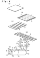
- Fig. 1 illustrates a dry cell 17 according to the embodiment of the present invention, in which (a) is a perspective view of an upper part of the dry cell, (b) is a plan view of the same, (c) is a half cut-away longitudinal cross sectional view of the same, and (d) is a front view of a blank 19 of an outer metal jacket 18 of the dry cell 17.
- a characteristic of this dry cell 17 is that its curled abutment joint 20 is formed at upper and lower ends of the outer metal jacket 18 along a direction S being different from the radial direction R of the metal jacket 18 as shown in Figs. 1(a) and (b).
- the blank 19 for the metal jacket 18 has notches 21a and 21b at only two corners thereof between one side 19a and an upper and lower sides 19c, 19d, and the other side 19b is not provided with any notches as best shown in Fig. 1(d). Since the two notches 21a and 21b are formed on one side edge 19a of the blank 19, the width 2d of the notches is two times greater than that of the conventional notches while the height h which is equal to an inward curling margin of the metal jacket 18 remains the same.
- a separator 23 impregnated with an electrolyte is fixedly disposed to the inner wall of an anode zinc can 22 of a cylindrical shape with a bottom, and filled with a cathode active material or a cathode mixture 24.
- a carbon electrode 27 serving as a collector is extended through the center of the cathode mixture 24.
- the upper opening of the anode zinc can 22 is hermetically sealed with a seal member 28 through which the carbon electrode 27 penetrates.
- the bottom face of the anode zinc can 22 is capped with a negative terminal plate 29, while the protruded upper end of the carbon electrode 27 is capped with a positive terminal plate 30.
- the cathode mixture 24 may be made of a mixture of an active material such as manganese dioxide and a conductive material such as acetylene black or graphite added with an electrolyte, and is compressed to be a cylindrical form and tightly pressed around the carbon electrode 27.
- the cathode mixture 24 is wrapped with the separator 23 and loaded in the anode zinc can 22, which is then coated with an insulating tube 31 thus constituting a cell member 26.
- the cell member 26 is inserted into the outer metal jacket 18 which is crimped at the upper end thereof and fixedly accommodated in the metal jacket 18 with an upper insulating ring 52 inserted therebetween.
- the reference numeral 53 denotes a lower seal ring.
- Fig. 2 shows the steps in producing order.
- a hoop material made of tin-plated steel being about 0.2 mm in thickness is cut into rectangular sheets 1 of given dimensions similarly with the prior art.
- the sheet 1 is then cut with a slitter along the cutting lines denoted by the two-dot parallel chain lines and divided into a pair of edge strips 32 of about 2 mm wide and a given number of first intermediate strips 33 of a rectangular shape parallel to the edge strips 32, as shown in Fig. 2(b).
- the first intermediate strip 33 is trimmed at both lengthwise ends by slitting and cut along a group of parallel cutting lines which cross at right angles with the lengthwise direction to obtain second intermediate strips 34 of a smaller rectangular shape, as shown in Fig. 2(c).
- the length of the second intermediate strip 34 is 1 mm longer than that of the two blanks 19 arranged adjacent to each other.
- the second intermediate strip 34 is separated into two metal jacket blanks 19 as shown in Fig. 2(e) or Fig. 1(d) with a punching tool 37 by cutting at right angles with respect to the lengthwise direction at its center.
- the punching tool 37 comprises a slit forming portion 37a for making a cutting slit of about 1 mm wide and a pair of substantially triangular notch forming portions 37b and 37c connected to either end of the slit forming portion 37a.
- Each end of the notch forming portions 37b and 37c is greatest in width which is equal to a sum of two times the width 2d of the notch 21 and the 1 mm width of the slit forming portion 37a. Accordingly, the notch forming portions 37b and 37c of the punching tool 37 are of greater size for cutting a couple of the notches 21, of which width 2d is two times greater than that of the notch 9 in the conventional method.
- the blanks 19 are obtained by punching each of the group of second intermediate strips 34 which are divided from the first intermediate strip 33 in this embodiment.
- the waste of material in the cutting of the blanks 19 is thus decreased to about 1/4 of that in the conventional method of producing the outer metal jacket 18.
- the number of the blanks 19 cut out from the given size of the sheet 1 is increased, enhancing the productivity accordingly.
- the productivity was increased by about 6 percent according to experiments as compared with the prior art. This increase will yield various economical merits since the small dry cells are manufactured in a great amount recently.
- burrs 38 are created on both sides of the blanks as shown in Fig. 2(f) in the cutting process to form the slits shown in Figs. 2(b), (c) and in the punching process to divide the strips into blanks with the punching tool 37 as shown in Fig. 2(d).
- a step shown in Fig. 2(f) for pounding the burrs is thus provided in which the blank 19 is placed on a bed 40 and vertically hammered with burr hammers 39 to remove the burrs 38.
- the blank 19 is rolled so that its sides 19a and 19b are abutted each other as shown in Fig. 2(g). Further, the lower end 19c is inwardly curled to make the cylindrical outer metal jacket 18 with a bottom.
- the cell member 26 is loaded into the metal jacket 18 with the upper insulating ring 52 and the lower seal ring 53 as shown in Fig. 1(c).
- the upper end 19d of the metal jacket 18 is then inwardly crimped to press the edge of the metal jacket 18 onto the terminal surface of the cell member 26, with the upper insulating ring 52 firmly placed therebetween, completing the small cylindrical dry cell 17 as shown in Fig. 1(c).
- a mold 41 shown in Fig. 3 is used for crimping the upper end 19d of the outer metal jacket 18, a mold 41 shown in Fig. 3 is used.
- Fig. 3 illustrates a longitudinal cross section of one half of the mold 41 of a cylindrical shape.
- the mold 41 has a pre-bending surface 41b extending upwardly and obliquely from a bending start end 41a toward the center and a bending surface 41c curving from the upper end of the pre-bending surface 41b downwardly to the center.
- the upper end 19d of the metal jacket 18 loaded with the cell member 26 is curled by being firmly pressed into the mold 41 from below.
- Denoted by the two dot chain line is the configuration of the mold P in the prior art for comparison with the present invention.
- the blank 19 for the outer metal jacket 18 has the notches 21 at the upper and lower ends of only one side edge 19a thereof.
- the upper and lower notches 21a and 21b come into direct contact with their corresponding edges of the other side edge 19b at the very end of the curling action.
- the upper end 19c is freely curled along the pre-bending surface 41b towards the center of the mold 41, and the notches come to join with the other end 19b to form the curled abutment join 20 at the very end of the curling action.
- the bending stress is thus not concentrated locally to the curled abutment joint 20, thus creating no dents caused by the buckling.
- one side edge 20a having the notch 21a is less rigid than the other side edge 20b without the notch.
- the side edge 20a is more prone to curl up on receipt of the gas pressure, creating a gap, through which the gas can escape to the outside.
- the dry cell according to the present invention thus has improved performance of preventing explosions.
- the notches 21a and 21b are not limited to the straight configuration as has been described but may be formed in any appropriate shapes such as an outwardly curved convexed notch 42 or an inwardly curved concaved notch 43 as shown in Figs. 4(a) and (b). In either case, the width of the notches 42 and 43 is set to be two times greater than the width d of the prior art in which notches are provided at both edges of the blank.
- the yield of products was increased by about 9 percent as compared with the conventional method hence considerably contributing to economical profits.
- the present invention is advantageous in producing dry cells or outer metal jackets of the dry cells more efficiently and productively.
Abstract
Description
- The present invention relates to a dry cell which is relatively small in size and has a cylindrical appearance and to a method of manufacturing an outer metal jacket of the dry cell.
- Since the material for outer jackets of a small cylindrical dry cell was changed from paper to metal, its leakage proof capacity has been improved thus increasing the performance of the dry cell. Such a metallic outer jacket of a dry cell (referred to as simply an outer metal jacket) is commonly fabricated in such a producing process as shown in Fig. 6. The procedure starts with cutting a hoop material of about 0.2mm thickness made of tin-plated steel into rectangular base sheets 1 of predetermined dimensions, for example 785 mm wide and 850 mm long, as shown in Fig. 6(a). This is followed by slitting and trimming two edges of about 2 mm width along both opposing sides of the base sheet 1. After removing the two edge pieces 2, slits are formed which are equally spaced and parallel to the sides of the base sheet 1 as denoted by the two-dot chain lines in Fig. 6(b). The base sheet 1 is then cut along these slits into a group of intermediate strips 3 as shown in Fig. 6(c). Each intermediate strip 3 is punched out with a given blanking die as shown in Fig. 6(d), thus producing a number of
metal jacket blanks 4 shown in Fig. 6(e). - The metal jacket blank 4 is then rolled to a cylindrical shape as shown in Fig. 6(f). While two
side edges outer metal jacket 7 with a bottom. Theouter metal jacket 7 is loaded through the open end thereof with a cell member which comprises a power generating element filled in a zinc can and is coated with an insulating tube. Theupper end 4d of theouter metal jacket 7 is then inwardly crimped to be pressed via an insulating ring against the shoulder of the cell member, thus producing a small cylindricaldry cell 8 as shown in Fig. 5. - The rectangular blank 4 punched out from the intermediate strip 3 has
notches upper end 4d is crimped inwardly with the cell member loaded therein, each pair ofnotches joint 10 between the twoside edges outer metal jacket 7, forming a curledabutment joint 11 as shown in Fig. 5. - More specifically, for forming the
curled abutment joint 11, the periphery of theouter metal jacket 7 at its upper end is pressed into a specific semicylindrical curling mold which has a curved cross section. As the upper end of theouter metal jacket 7 is gradually bent to form an even curve all around its periphery, theopposing notches notches abutment joint 11 and the bending stress is concentrated thereon thus causing buckling. - Further, the cell member loaded in the
outer metal jacket 7 varies in height. If the cell member is short, an extra stress is given after the twonotches curled abutment joint 11. Such bending stress being locally concentrated causesdents 12 on either side of the abutment joint as shown in Fig. 5, which damage the appearance of theouter metal jacket 7. Also, the twonotches curled abutment joint 11, thus firmly pressing a seal member of the cell, which may obstruct the discharge of a gas from the cell in case that the gas pressure inside thecell 8 soars unexpectedly. - In order for preventing the buckling, an improved cylindrical dry cell has been proposed in which four corners of an outer metal jacket blank at upper and lower ends of both sides are rounded off by removing segments of different lengths or heights which are determined in a specific ratio (as disclosed in Japanese Utility-model Publication No. 1-19053). However, it is necessary to cut the blank of the cylindrical dry cell to a desired shape under precise control of the blanking operation. Especially for producing dry cells of small size, it is difficult to precisely control the configuration of tiny blanks when punching them out. On the other hand, the outer metal jacket for dry cells of larger size is jointed by laser welding, whereby the buckling is prevented. However, the laser welding is generally not utilized for producing small dry cells because of its low productivity and high producing cost.
- In order to form the
small notches metal jacket blanks 4 in the producing process of theouter metal jacket 7 described above, there is virtually no alternative but to punch out a plurality ofblanks 4 from the rectangular intermediate strip 3 which is slightly greater in width than a pair ofblanks 4 arranged side by side as shown in Fig. 6(d). When the dry cell is large in overall size, the notches may be provided by cutting off four corners of a rectangular strip. However, thenotches sides sides such minute notches - Accordingly, a waste of material is left in a large amount after the intermediate strip 3 is punched out as can be seen from Fig. 6(d). The number of the
blanks 4 punched out from the intermediate strip 3 is limited thus being inefficient in production. In light of the mass production of small dry cells in recent years, such method as described above which creates the loss of material is unfavorable from the economical point of view. - It is thus an object of the present invention to provide a dry cell having such a configuration that any dents caused by the buckling when crimped is effectively prevented, and a method of producing the outer metal jackets efficiently.
- EP-A-333023 discloses a dry cell with a metal jacket having notches at both corners at one side edge.
- In order to solve the above described problems, the present invention provides a dry cell including a cylindrical cell member and an outer metal jacket for encasing the cell member, the metal jacket being formed by rolling a metal jacket blank of a rectangular metal strip into a cylindrical shape to cause both side edges thereof to abut each other and by inwardly curling and crimping a lower end of the blank to make a bottom, the cell member being sealed in the metal jacket by inwardly curling and crimping an upper end of the metal jacket, wherein
the metal jacket blank is provided with notches at both corners of one side edge thereof where the abutment joint is formed, and that the notches are respectively adjoined to an upper end and a lower end of the other side edge of the blank, forming a curled abutment joint along a direction which is different from the radial direction of the metal jacket, and characterised in that: - the width of the notches at one side edge of the metal jacket blank is determined to correspond with the length of the other side edge which exceeds a line of the radial direction at both ends of the cylindrical metal jacket. thereof to abut each other and by inwardly curling and crimping a lower end of the blank to make a bottom, the cell member being sealed in the metal jacket by inwardly curling and crimping an upper end of the metal jacket, and is characterized in that: the metal jacket blank is provided with notches at both corners of one side edge thereof where the abutment joint is formed, and that the notches are respectively adjoined to an upper end and a lower end of the other side edge of the blank, forming a curled abutment joint along a direction which is different direction of the metal jacket.
- The blank for the metal jacket has the notches at the upper and lower ends of only one side thereof. Thus, the upper and lower notches come into direct contact with their corresponding edges of the other side at the very end of the curling action. As the notches come to join with the other end to form the curled abutment joint at the very end of the curling action, the bending stress is not concentrated locally to the curled abutment joint, thus creating no dents caused by the buckling.
- The invention permits the two notches at the side edge of the blank to be adjoined to their respective upper and lower ends of the other side without making gaps. The curled abutment joint of a favorable configuration can be formed, contributing to a better appearance of the dry cell.
- According to the present invention there is provided a method of producing a dry cell outer metal jacket for encasing a cell member therein, comprising the steps of:
- cutting a rectangular sheet of a metallic material along the lines at equal intervals parallel to one side of the sheet to form a plurality of first intermediate strips of a rectangular shape;
- cutting the first intermediate strip along the lines at equal intervals being orthogonal to the lengthwise direction to form a plurality of second intermediate strips of a rectangular shape;
- cutting the second intermediate strip with a press cutter into two pieces along a line in the middle and at the same time removing both edges of substantially a triangular shape at either end along the line, so as to form a pair of metal jacket blanks of the same shape respectively having notches at upper and lower ends of only one side edge thereof; and
- rolling the blank into a cylindrical shape to cause two opposite sides to abut each other and inwardly curling and crimping the lower end of the cylindrical blank to make a bottom.
- According to such method of producing the outer metal jackets, the notches can be readily and quickly provided at both upper and lower edges of only one side edge of the metal jacket blank when dividing the second intermediate strips into two blanks in the punching process. This is because the second intermediate strip can be secured at both sides of the cutting line when being punched, and because it is unnecessary to provide notches at upper and lower edges of the other side of the blank as in the prior art.
- As compared with the conventional method in which a group of intermediate blanks of a rectangular shape are punched out from a material sheet, the method of the present invention minimizes the waste of material after the blanks are punched and rolled to the metal jackets. The number of the blanks cut out from the material sheet is increased thus improving the efficiency of production. Since the dry cells are produced in great quantity, greater economy of material can be attained.
- It is preferable that the second intermediate strip is divided into the two metal jacket blanks by the press cutting action with a punching tool which comprises a slit forming portion having a width of about 1 mm and a pair of substantially triangular notch forming portions connected uniformly to either end of the slit forming portion. The life of the punching tool can be lengthened due to such configuration.
- The dry cell according to the present invention can be readily produced by the method of the present invention, in which the upper end of the outer metal jacket is inwardly curled and crimped after a cell member of a cylindrical shape is loaded into the metal jacket from the upper opening thereof.
-
- Fig. 1 illustrates a dry cell according to one embodiment of the present invention, in which (a) is a perspective view of an upper part of the dry cell, (b) is a plan view of the same, (c) is a half cut-away longitudinal cross sectional view of the same, and (d) is a front view of a blank of an outer metal jacket;
- Fig. 2 shows steps from (a) to (g) of producing the outer metal jacket of the dry cell;
- Fig. 3 is a half longitudinal cross sectional view of a mold designed for crimping the outer metal jacket;
- Figs. 4(a) and (b) are front views showing modifications of the blank;
- Fig. 5 is a perspective view of a conventional dry cell; and
- Fig. 6 shows steps from (a) to (f) of producing the outer metal jacket of the conventional dry cell.
- Preferred embodiments of the present invention will be described in details referring to the accompanying drawings. Fig. 1 illustrates a
dry cell 17 according to the embodiment of the present invention, in which (a) is a perspective view of an upper part of the dry cell, (b) is a plan view of the same, (c) is a half cut-away longitudinal cross sectional view of the same, and (d) is a front view of a blank 19 of anouter metal jacket 18 of thedry cell 17. A characteristic of thisdry cell 17 is that its curled abutment joint 20 is formed at upper and lower ends of theouter metal jacket 18 along a direction S being different from the radial direction R of themetal jacket 18 as shown in Figs. 1(a) and (b). The blank 19 for themetal jacket 18 hasnotches side 19a and an upper andlower sides other side 19b is not provided with any notches as best shown in Fig. 1(d). Since the twonotches side edge 19a of the blank 19, thewidth 2d of the notches is two times greater than that of the conventional notches while the height h which is equal to an inward curling margin of themetal jacket 18 remains the same. - The structure of the
dry cell 17 is now explained. As shown in Fig. 1(c), aseparator 23 impregnated with an electrolyte is fixedly disposed to the inner wall of an anode zinc can 22 of a cylindrical shape with a bottom, and filled with a cathode active material or acathode mixture 24. Acarbon electrode 27 serving as a collector is extended through the center of thecathode mixture 24. The upper opening of the anode zinc can 22 is hermetically sealed with aseal member 28 through which thecarbon electrode 27 penetrates. The bottom face of the anode zinc can 22 is capped with anegative terminal plate 29, while the protruded upper end of thecarbon electrode 27 is capped with a positiveterminal plate 30. Thecathode mixture 24 may be made of a mixture of an active material such as manganese dioxide and a conductive material such as acetylene black or graphite added with an electrolyte, and is compressed to be a cylindrical form and tightly pressed around thecarbon electrode 27. Thecathode mixture 24 is wrapped with theseparator 23 and loaded in the anode zinc can 22, which is then coated with an insulatingtube 31 thus constituting acell member 26. Thecell member 26 is inserted into theouter metal jacket 18 which is crimped at the upper end thereof and fixedly accommodated in themetal jacket 18 with an upper insulatingring 52 inserted therebetween. Thereference numeral 53 denotes a lower seal ring. - The procedure of manufacturing the
outer metal jacket 18 of thedry cell 17 will be explained referring to Fig. 2 which shows the steps in producing order. As shown in Fig. 2(a), a hoop material made of tin-plated steel being about 0.2 mm in thickness is cut into rectangular sheets 1 of given dimensions similarly with the prior art. The sheet 1 is then cut with a slitter along the cutting lines denoted by the two-dot parallel chain lines and divided into a pair of edge strips 32 of about 2 mm wide and a given number of firstintermediate strips 33 of a rectangular shape parallel to the edge strips 32, as shown in Fig. 2(b). The firstintermediate strip 33 is trimmed at both lengthwise ends by slitting and cut along a group of parallel cutting lines which cross at right angles with the lengthwise direction to obtain secondintermediate strips 34 of a smaller rectangular shape, as shown in Fig. 2(c). The length of the secondintermediate strip 34 is 1 mm longer than that of the twoblanks 19 arranged adjacent to each other. - As shown in Fig. 2(d), the second
intermediate strip 34 is separated into twometal jacket blanks 19 as shown in Fig. 2(e) or Fig. 1(d) with apunching tool 37 by cutting at right angles with respect to the lengthwise direction at its center. Thepunching tool 37 comprises aslit forming portion 37a for making a cutting slit of about 1 mm wide and a pair of substantially triangularnotch forming portions 37b and 37c connected to either end of theslit forming portion 37a. Each end of thenotch forming portions 37b and 37c is greatest in width which is equal to a sum of two times thewidth 2d of the notch 21 and the 1 mm width of theslit forming portion 37a. Accordingly, thenotch forming portions 37b and 37c of thepunching tool 37 are of greater size for cutting a couple of the notches 21, of whichwidth 2d is two times greater than that of thenotch 9 in the conventional method. - As compared with the conventional method in which the
metal jacket blanks 4 are punched out from the intermediate strip 3 (Fig. 6), theblanks 19 are obtained by punching each of the group of secondintermediate strips 34 which are divided from the firstintermediate strip 33 in this embodiment. The waste of material in the cutting of theblanks 19 is thus decreased to about 1/4 of that in the conventional method of producing theouter metal jacket 18. The number of theblanks 19 cut out from the given size of the sheet 1 is increased, enhancing the productivity accordingly. The productivity was increased by about 6 percent according to experiments as compared with the prior art. This increase will yield various economical merits since the small dry cells are manufactured in a great amount recently. - It is inevitable that
burrs 38 are created on both sides of the blanks as shown in Fig. 2(f) in the cutting process to form the slits shown in Figs. 2(b), (c) and in the punching process to divide the strips into blanks with thepunching tool 37 as shown in Fig. 2(d). A step shown in Fig. 2(f) for pounding the burrs is thus provided in which the blank 19 is placed on abed 40 and vertically hammered with burr hammers 39 to remove theburrs 38. - After the
burrs 38 are removed, the blank 19 is rolled so that itssides lower end 19c is inwardly curled to make the cylindricalouter metal jacket 18 with a bottom. Thecell member 26 is loaded into themetal jacket 18 with the upper insulatingring 52 and thelower seal ring 53 as shown in Fig. 1(c). Theupper end 19d of themetal jacket 18 is then inwardly crimped to press the edge of themetal jacket 18 onto the terminal surface of thecell member 26, with the upper insulatingring 52 firmly placed therebetween, completing the small cylindricaldry cell 17 as shown in Fig. 1(c). - For crimping the
upper end 19d of theouter metal jacket 18, amold 41 shown in Fig. 3 is used. Fig. 3 illustrates a longitudinal cross section of one half of themold 41 of a cylindrical shape. Themold 41 has apre-bending surface 41b extending upwardly and obliquely from a bendingstart end 41a toward the center and a bending surface 41c curving from the upper end of thepre-bending surface 41b downwardly to the center. Theupper end 19d of themetal jacket 18 loaded with thecell member 26 is curled by being firmly pressed into themold 41 from below. Denoted by the two dot chain line is the configuration of the mold P in the prior art for comparison with the present invention. - The blank 19 for the
outer metal jacket 18 has the notches 21 at the upper and lower ends of only oneside edge 19a thereof. Thus, the upper andlower notches other side edge 19b at the very end of the curling action. As it is not necessary to gradually adjoin the notches of the blank from the outer side toward the inner side as in the prior art arrangement, theupper end 19c is freely curled along thepre-bending surface 41b towards the center of themold 41, and the notches come to join with theother end 19b to form the curled abutment join 20 at the very end of the curling action. The bending stress is thus not concentrated locally to the curled abutment joint 20, thus creating no dents caused by the buckling. - Of the curled abutment joint 20, one
side edge 20a having thenotch 21a is less rigid than theother side edge 20b without the notch. In case that the gas pressure inside the cell soars unexpectedly, theside edge 20a is more prone to curl up on receipt of the gas pressure, creating a gap, through which the gas can escape to the outside. The dry cell according to the present invention thus has improved performance of preventing explosions. - The
notches convexed notch 42 or an inwardlycurved concaved notch 43 as shown in Figs. 4(a) and (b). In either case, the width of thenotches - According to the method of producing the
outer metal jacket 18 of the present invention, the yield of products was increased by about 9 percent as compared with the conventional method hence considerably contributing to economical profits. - As set forth above, the present invention is advantageous in producing dry cells or outer metal jackets of the dry cells more efficiently and productively.
Claims (4)
- A dry cell including a cylindrical cell member (26) and an outer metal jacket (18) for encasing the cell member (26), the metal jacket (18) being formed by rolling a metal jacket blank (19) of a rectangular metal strip into a cylindrical shape to cause both side edges (19a, 19b) thereof to abut each other and by inwardly curling and crimping a lower end (19c) of the blank (19) to make a bottom, the cell member (26) being sealed in the metal jacket (18) by inwardly curling and crimping an upper end (19d) of the metal jacket (18), wherein
the metal jacket blank (19) is provided with notches (21a,21b) at both corners of one side edge (19a) thereof where the abutment joint (10) is formed, and that the notches are respectively adjoined to an upper end and a lower end of the other side edge (19b) of the blank (19), forming a curled abutment joint (20) along a direction (S) which is different from the radial direction (R) of the metal jacket (18), and characterised in that:the width (2d) of the notches (21a,21b) at one side edge (19a) of the metal jacket blank (19) is determined to correspond with the length of the other side edge (19b) which exceeds a line of the radial direction (R) at both ends of the cylindrical metal jacket (18). - A method of producing a dry cell outer metal jacket (18) for encasing a cell member (26) therein, comprising the steps of:cutting a rectangular sheet (1) of a metallic material along the lines at equal intervals parallel to one side of the sheet to form a plurality of first intermediate strips (33) of a rectangular shape;cutting the first intermediate strip (33) along the lines at equal intervals being orthogonal to the lengthwise direction to form a plurality of second intermediate strips (34) of a rectangular shape;cutting the second intermediate strip (34) with a press cutter into two pieces along a line in the middle and at the same time removing both edges of substantially a triangular shape at either end along the line, so as to form a pair of metal jacket blanks (19) of the same shape respectively having notches (21a,21b) at upper and lower ends of only one side edge (19a) thereof; androlling the blank (19) into a cylindrical shape to cause two opposite sides (19a, 19b) to abut each other and inwardly curling and crimping the lower end of the cylindrical blank (19) to make a bottom.
- A method of producing a dry cell outer metal jacket according to claim 2, wherein the second intermediate strip (34) is divided into the two metal jacket blanks (19) by the press cutting action with a punching tool (37) which comprises a slit forming portion (37a) having a width of about 1 mm and a pair of substantially triangular notch forming portions (37a, 37b) connected uniformly to either end of the slit forming portion (37a).
- A method of producing a dry cell comprising the steps of producing an outer metal jacket according to the method of claim 2 or 3, and further comprising the steps of inwardly curling and crimping the upper end of the metal jacket (18) after a cell member of a cylindrical shape is loaded into the metal jacket (18) from the upper opening thereof to the complete dry cell (17).
Applications Claiming Priority (1)
| Application Number | Priority Date | Filing Date | Title |
|---|---|---|---|
| PCT/JP1997/003093 WO1999012218A1 (en) | 1997-09-03 | 1997-09-03 | Dry cell and method of manufacturing outer can therefor |
Publications (3)
| Publication Number | Publication Date |
|---|---|
| EP0951079A1 EP0951079A1 (en) | 1999-10-20 |
| EP0951079A4 EP0951079A4 (en) | 2004-09-29 |
| EP0951079B1 true EP0951079B1 (en) | 2007-01-03 |
Family
ID=14181070
Family Applications (1)
| Application Number | Title | Priority Date | Filing Date |
|---|---|---|---|
| EP97939161A Expired - Lifetime EP0951079B1 (en) | 1997-09-03 | 1997-09-03 | Dry cell and method of manufacturing outer can therefor |
Country Status (7)
| Country | Link |
|---|---|
| US (1) | US6228530B1 (en) |
| EP (1) | EP0951079B1 (en) |
| JP (1) | JP3129743B2 (en) |
| BR (1) | BR9712725A (en) |
| DE (1) | DE69737207T2 (en) |
| ID (1) | ID21388A (en) |
| WO (1) | WO1999012218A1 (en) |
Families Citing this family (6)
| Publication number | Priority date | Publication date | Assignee | Title |
|---|---|---|---|---|
| JP2001062525A (en) * | 1999-08-25 | 2001-03-13 | Matsushita Electric Ind Co Ltd | Steel sheet die cutting device |
| KR101182274B1 (en) * | 2010-10-13 | 2012-09-13 | 삼성에스디아이 주식회사 | Rechargeable battery and manufacturing method of the same |
| JP5555605B2 (en) * | 2010-10-29 | 2014-07-23 | 株式会社アマダ | Deburring device |
| JP5555665B2 (en) * | 2011-05-20 | 2014-07-23 | 日立ビークルエナジー株式会社 | Cylindrical secondary battery |
| CN104308543A (en) * | 2014-09-10 | 2015-01-28 | 温岭市圣光电池设备厂 | Exterior notching machine for rotary cell zinc tube |
| CN107552636A (en) * | 2017-09-07 | 2018-01-09 | 乳源东阳光机械有限公司 | A kind of full-automatic paper tinsel sample stamping machine |
Family Cites Families (13)
| Publication number | Priority date | Publication date | Assignee | Title |
|---|---|---|---|---|
| FR1594449A (en) * | 1968-12-12 | 1970-06-01 | ||
| JPS4814812B1 (en) * | 1969-08-01 | 1973-05-10 | ||
| US3660168A (en) * | 1970-04-09 | 1972-05-02 | Mallory & Co Inc P R | Leak-proof primary cell |
| US3630783A (en) * | 1970-05-11 | 1971-12-28 | Mallory Battery Canada | Heat-shrinkable packaging for batteries |
| US3859137A (en) * | 1971-03-26 | 1975-01-07 | Accumulateurs Fixes | Cylindrical electrochemical cells |
| JPS54139845A (en) | 1978-04-24 | 1979-10-30 | Tomio Okuyama | Apparatus for making can shell for double wind fastening |
| US4227701A (en) * | 1979-01-02 | 1980-10-14 | Fuji Electrochemical Co., Ltd. | Rupturable sealing structure of cell |
| JPH062872B2 (en) | 1986-06-23 | 1994-01-12 | 竹本油脂株式会社 | Unsaturated polyester curable resin composition |
| JPS633056U (en) * | 1986-06-25 | 1988-01-09 | ||
| JPS6314360A (en) | 1986-07-04 | 1988-01-21 | Fujitsu General Ltd | Video tape recorder |
| JPS6314360U (en) * | 1986-07-14 | 1988-01-30 | ||
| US4722874A (en) * | 1986-08-01 | 1988-02-02 | Moli Energy Limited | Electrochemical cell pressure relief devices |
| JPH0682546B2 (en) | 1988-03-10 | 1994-10-19 | 松下電器産業株式会社 | Outer can and dry battery using the same |
-
1996
- 1996-01-16 ID IDP980047D patent/ID21388A/en unknown
-
1997
- 1997-09-03 WO PCT/JP1997/003093 patent/WO1999012218A1/en active IP Right Grant
- 1997-09-03 DE DE69737207T patent/DE69737207T2/en not_active Expired - Lifetime
- 1997-09-03 JP JP10507826A patent/JP3129743B2/en not_active Expired - Fee Related
- 1997-09-03 EP EP97939161A patent/EP0951079B1/en not_active Expired - Lifetime
- 1997-09-03 US US09/269,956 patent/US6228530B1/en not_active Expired - Fee Related
- 1997-09-03 BR BR9712725-6A patent/BR9712725A/en not_active IP Right Cessation
Also Published As
| Publication number | Publication date |
|---|---|
| EP0951079A1 (en) | 1999-10-20 |
| JP3129743B2 (en) | 2001-01-31 |
| BR9712725A (en) | 1999-10-26 |
| WO1999012218A1 (en) | 1999-03-11 |
| ID21388A (en) | 1999-06-03 |
| DE69737207T2 (en) | 2007-10-04 |
| EP0951079A4 (en) | 2004-09-29 |
| US6228530B1 (en) | 2001-05-08 |
| DE69737207D1 (en) | 2007-02-15 |
Similar Documents
| Publication | Publication Date | Title |
|---|---|---|
| US4728842A (en) | Laminated assembly for a dynamoelectric machine and method for manufacturing laminated assemblies having ridges formed on projections which interlock with recesses of adjacent laminations | |
| US20230124818A1 (en) | Battery grid with varied corrosion resistance | |
| CN102380534A (en) | Producing method of compact | |
| US6944942B2 (en) | Apparatus for one-step rotary forming of uniform expanded mesh | |
| EP0951079B1 (en) | Dry cell and method of manufacturing outer can therefor | |
| JP5159007B2 (en) | Manufacturing method of battery electrode plate | |
| JP5196898B2 (en) | Method for fixing lid member to container, metal sealed container and sealed battery | |
| US4809429A (en) | Apparatus for manufacturing laminated assemblies having ridges formed on projections which interlock with recesses of adjacent laminations | |
| CN209843829U (en) | Multi-contact conducting strip for series connection of cylindrical batteries | |
| US4545108A (en) | Cold-welding of electrolytic capacitor rolls | |
| US6678926B2 (en) | Method and apparatus for manufacturing battery plates | |
| JPH0142115B2 (en) | ||
| JP7384728B2 (en) | Manufacturing method for plate-shaped parts | |
| CN1106047C (en) | Dry cell and method of manufacturing outer can therefor | |
| US4448055A (en) | Method to manufacture pole pieces for dynamo electric machine, and so-made pole piece | |
| JPH04132156A (en) | Battery | |
| JPH11260373A (en) | Manufacture of spreading mesh sheet and its manufacturing equipment | |
| JP3247570B2 (en) | Battery can manufacturing method | |
| PL188177B1 (en) | Dry cell and a method of manufacturing of external metallic jacket for the dry cell | |
| JPH06333541A (en) | Rectangular battery can and its manufacture and device for forming rectangular vessel for rectangular battery | |
| WO2023195526A1 (en) | Electrolytic capacitor lead terminal, device for manufacturing rolled part, and method for manufacturing rolled part | |
| JPH0717144Y2 (en) | Punch for molding capacitor electrode terminals | |
| JPS6252450B2 (en) | ||
| JP2982498B2 (en) | Method for producing expanded grid for lead-acid battery and cutter for producing the same | |
| JPH0116288Y2 (en) |
Legal Events
| Date | Code | Title | Description |
|---|---|---|---|
| PUAI | Public reference made under article 153(3) epc to a published international application that has entered the european phase |
Free format text: ORIGINAL CODE: 0009012 |
|
| 17P | Request for examination filed |
Effective date: 19990528 |
|
| AK | Designated contracting states |
Kind code of ref document: A1 Designated state(s): DE FR GB |
|
| A4 | Supplementary search report drawn up and despatched |
Effective date: 20040813 |
|
| GRAP | Despatch of communication of intention to grant a patent |
Free format text: ORIGINAL CODE: EPIDOSNIGR1 |
|
| GRAS | Grant fee paid |
Free format text: ORIGINAL CODE: EPIDOSNIGR3 |
|
| GRAA | (expected) grant |
Free format text: ORIGINAL CODE: 0009210 |
|
| AK | Designated contracting states |
Kind code of ref document: B1 Designated state(s): DE FR GB |
|
| REG | Reference to a national code |
Ref country code: GB Ref legal event code: FG4D |
|
| REF | Corresponds to: |
Ref document number: 69737207 Country of ref document: DE Date of ref document: 20070215 Kind code of ref document: P |
|
| ET | Fr: translation filed | ||
| PLBE | No opposition filed within time limit |
Free format text: ORIGINAL CODE: 0009261 |
|
| STAA | Information on the status of an ep patent application or granted ep patent |
Free format text: STATUS: NO OPPOSITION FILED WITHIN TIME LIMIT |
|
| 26N | No opposition filed |
Effective date: 20071005 |
|
| PGFP | Annual fee paid to national office [announced via postgrant information from national office to epo] |
Ref country code: GB Payment date: 20090902 Year of fee payment: 13 |
|
| PGFP | Annual fee paid to national office [announced via postgrant information from national office to epo] |
Ref country code: DE Payment date: 20090827 Year of fee payment: 13 |
|
| PGFP | Annual fee paid to national office [announced via postgrant information from national office to epo] |
Ref country code: FR Payment date: 20091012 Year of fee payment: 13 |
|
| GBPC | Gb: european patent ceased through non-payment of renewal fee |
Effective date: 20100903 |
|
| REG | Reference to a national code |
Ref country code: FR Ref legal event code: ST Effective date: 20110531 |
|
| REG | Reference to a national code |
Ref country code: DE Ref legal event code: R119 Ref document number: 69737207 Country of ref document: DE Effective date: 20110401 |
|
| PG25 | Lapsed in a contracting state [announced via postgrant information from national office to epo] |
Ref country code: DE Free format text: LAPSE BECAUSE OF NON-PAYMENT OF DUE FEES Effective date: 20110401 Ref country code: FR Free format text: LAPSE BECAUSE OF NON-PAYMENT OF DUE FEES Effective date: 20100930 |
|
| PG25 | Lapsed in a contracting state [announced via postgrant information from national office to epo] |
Ref country code: GB Free format text: LAPSE BECAUSE OF NON-PAYMENT OF DUE FEES Effective date: 20100903 |