EP0950495B1 - Form für Rohrkrümmer - Google Patents
Form für Rohrkrümmer Download PDFInfo
- Publication number
- EP0950495B1 EP0950495B1 EP97116065A EP97116065A EP0950495B1 EP 0950495 B1 EP0950495 B1 EP 0950495B1 EP 97116065 A EP97116065 A EP 97116065A EP 97116065 A EP97116065 A EP 97116065A EP 0950495 B1 EP0950495 B1 EP 0950495B1
- Authority
- EP
- European Patent Office
- Prior art keywords
- bend
- core
- set forth
- pivotal member
- connecting part
- Prior art date
- Legal status (The legal status is an assumption and is not a legal conclusion. Google has not performed a legal analysis and makes no representation as to the accuracy of the status listed.)
- Expired - Lifetime
Links
- 238000006073 displacement reaction Methods 0.000 claims description 6
- 238000001746 injection moulding Methods 0.000 claims description 3
- 239000000463 material Substances 0.000 claims 1
- 238000004519 manufacturing process Methods 0.000 description 3
- 230000001419 dependent effect Effects 0.000 description 1
- 238000011161 development Methods 0.000 description 1
- 230000018109 developmental process Effects 0.000 description 1
- 238000002347 injection Methods 0.000 description 1
- 239000007924 injection Substances 0.000 description 1
- 230000007704 transition Effects 0.000 description 1
Images


Classifications
-
- B—PERFORMING OPERATIONS; TRANSPORTING
- B29—WORKING OF PLASTICS; WORKING OF SUBSTANCES IN A PLASTIC STATE IN GENERAL
- B29C—SHAPING OR JOINING OF PLASTICS; SHAPING OF MATERIAL IN A PLASTIC STATE, NOT OTHERWISE PROVIDED FOR; AFTER-TREATMENT OF THE SHAPED PRODUCTS, e.g. REPAIRING
- B29C45/00—Injection moulding, i.e. forcing the required volume of moulding material through a nozzle into a closed mould; Apparatus therefor
- B29C45/17—Component parts, details or accessories; Auxiliary operations
- B29C45/26—Moulds
- B29C45/261—Moulds having tubular mould cavities
- B29C45/2614—Moulds having tubular mould cavities for manufacturing bent tubular articles using an undercut forming mould core
Definitions
- the invention relates to a device for injection molding plastic pipe elbows, the one manifold section with a circular arc-shaped center line and constant Internal cross-section and cylindrical on one or both sides adjoining it
- Cylinder core for each connection piece includes, for moving the pivoting part a displacement device is used, which is articulated on the swivel part, in one Connection piece includes longitudinally displaceable rod.
- the elbow section is not by means of a rod, but moved by tension elements, preferably by wire ropes, which penetrate the sliced manifold core. Because these disks must be mutually secured against shifting and twisting overall a very complex structure.
- the device according to US-A 3,095,613 can be on an actual manifold core waive at all, namely that the radius of curvature of the tube in Extremely small compared to the pipe diameter.
- the Cylinder cores are only small core segments in the area of the pipe bend simply hinged.
- US-A 3,152,365 relates to the manufacture of a telephone handset, it being the relative large end openings make it relatively easy to use a mandrel easy to pull articulated rod.
- No. 4,184,834 describes a device of the type defined at the outset for producing Pipe elbows, which have an elbow section with a circular center line and constant internal cross-section and two adjoining extended connecting pieces include, known.
- the manifold core part is articulated on one of the nozzle core parts attached and must be when inserting into the form and when demolding the elbow its path along the mold cavity or along the inner wall of the Find pipe elbow yourself. Only when all the core parts are finally put together the manifold core part is centered in the mold. The cutting plane between the leading cylindrical core part and the attached manifold core part is sufficient in into the manifold section.
- the connecting pieces are so short and wide that the distance of the manifold core part from the finished pipe only by pivoting of the curved manifold section around its center of curvature he follows.
- the object of the invention in contrast, is the production of elbows to make, where on the curved section an arbitrarily long cylinder socket connects.
- the displacement device two in the Manifold level includes spaced rods, and a positive guide, which is the ends of the rods articulated to the pivoting part in the elbow section on circular paths around the axis of curvature and in the adjoining one Connection stub leads parallel to this.
- the invention requires that the cylinder connecting piece has a larger diameter have than the curved tube part. However, this difference is said to be made fluidic reasons to be as small as possible. This is primarily because of this achieved that the swivel part only in the inserted state up to the center of the elbow enough. If there is also a long one on the second side of the manifold section Should connect connecting piece, the device according to the invention is symmetrical arranged twice.
- Another adjustment of the cross-sections of connecting pieces and manifold can be achieved in that the manifold core in addition to the pivoting part a slide located on the inside of the manifold section, which at pulled out cylinder core along the cylinder core and the swivel part in Direction on the axis of the connecting piece is displaceable.
- the manifold core in addition to the pivoting part a slide located on the inside of the manifold section, which at pulled out cylinder core along the cylinder core and the swivel part in Direction on the axis of the connecting piece is dis
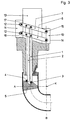
- an embodiment of the invention is shown in three stages of movement of the mandrel shown in section along the median plane of a pipe bend.
- Fig. 1 shows the mandrel according to the invention during the manufacture of the molded part represents which consists of a manifold section 8 in the form of a tubular segment and adjoining long or short connecting pieces 9, 22.
- the mold core consists of three parts, namely a cylinder core 13, a pivoting part 5 and one Slider 20. There is a between the cylinder core 13 and the slider 20 Spring 21, which the slide 20 in the direction of the axis of the connecting piece 9th acted upon.
- the bend section 8 is bent with a radius r around an axis of curvature, which pierces the drawing plane at point K.
- the diameter d of the molded part corresponds the radius of curvature r, but this is not a prerequisite for functioning of the invention. Rather, it is to be regarded as a particular advantage of the invention that you can work with a relatively large radius of curvature r.
- Rods 1 and 2 are connected to the pivot part 5 via joints, the Pivot axes lie in a radial plane through the axis of curvature K.
- the mold is removed after opening the outer mold in three separate phases the first one can be seen from FIG. 2.
- the cylinder core 13 is in the axial direction pulled out until he comes to rest on the guide block 11 with his stop 18.
- the pivot part 5 remains in its original position, whereas the slide 20 under the influence of the expanding spring 21 on the pivot part 5 in Axial direction slides and thus reaches the cylinder cross-section entirely
- the cylinder core 13 pulled out further and takes the guide block 11 with it. Since the Guide block 10 remains, by pivoting the strips 6 and 7, which pull out the rods 1 and 2 and thereby the pivoting part 5 from the Move elbow section 8 into the connector 9. In order for this to be possible, the Connection piece 9 have a slightly larger cross section than that Manifold section 8.
- the movement of the individual core parts can be controlled purely mechanically by a Slider take place, which has guide slots with which to be moved Parts 10 and 11 are engaged via lateral projections, such as in the DE-U 94 14 523 is shown. Electrical or hydraulic can do just as well Drives are used to move the rods 1, 2 through the described Sequence of movements and back again.
Landscapes
- Engineering & Computer Science (AREA)
- Manufacturing & Machinery (AREA)
- Mechanical Engineering (AREA)
- Moulds For Moulding Plastics Or The Like (AREA)
- Shaping Of Tube Ends By Bending Or Straightening (AREA)
- Bending Of Plates, Rods, And Pipes (AREA)
- Rigid Pipes And Flexible Pipes (AREA)
Description
Claims (7)
- Vorrichtung zum Spritzgießen von Rohrkrümmern aus Kunststoff, die einen Krümmerabschnitt (8) mit einer kreisbogenförmigen Mittellinie und gleichbleibendem Innenquerschnitt und ein- oder beidseitig daran anschließenden zylindrischen Anschlußstutzen (9,22) mit größerem Innenquerschnitt aufweisen, mit einer Spritzgießform, die in der Ebene der kreisbogenförmigen Mittellinie des Krümmerabschnitts (8) in zumindest zwei Außenformteile teilbar ist, die einen Formhohlraum bilden, und die einen Krümmerkem mit einem längs der kreisbogenförmigen Mittellinie des Krümmerbereiches verschwenkbaren Schwenkteil (5) und einen axial entlang seiner Mittelachse verschieblichen Zylinderkern (13) für jeden Anschlußstutzen (9,22) umfaßt, wobei zur Bewegung des Schwenkteils (5) eine Verschiebeeinrichtung dient, welche eine am Schwenkteil (5) angelenkte, in einem Anschlußstutzen (9;22) längsverschiebbare Stange umfaßt, dadurch gekennzeichnet, daß die Verschiebeeinrichtung zwei in der Krümmerebene voneinander distanzierte Stangen (1,2) umfaßt, sowie eine Zwangsführung, welche die an den Schwenkteil (5) angelenkten Enden (3,4) der Stangen (1,2) im Krümmerabschnitt (8) auf Kreisbahnen um die Krümmungs-achse (K) und im daran anschließenden Anschlußstutzen (9) parallel zu diesem führt.
- Vorrichtung nach Anspruch 1, dadurch gekennzeichnet, daß zur Führung der Stangen (1,2) zwei schwenkbare Leisten (6,7) dienen, deren Schwenkachsen (14,15) in einer die Krümmungsachse (K) enthaltenden Ebene liegen, und welche alternativ zur Verschwenkung gemeinsam in Richtung des Anschlußstutzens (9) verschiebbar sind.
- Vorrichtung nach Anspruch 2, dadurch gekennzeichnet, daß die Schwenkachsen (14,15) und die freien Enden (16,17) der Leisten (6,7) in je einem parallel zum Anschlußstutzen (9) verschiebbaren Führungsblock (10,11) gelagert sind, wobei die Lagerung der freien Enden (16,17) in Langlöchern (12) erfolgt.
- Vorrichtung nach Anspruch 3, dadurch gekennzeichnet, daß die Führungsblöcke (10,11) durch in axialer Richtung des Anschlußstutzens (9) versetzte Anschläge (18,19) des Zylinderkerns (13) beim Ausfahren des Zylinderkerns (13) mitgenommen werden.
- Vorrichtung nach einem der Ansprüche 1 - 4, dadurch gekennzeichnet, daß der Schwenkteil (5) im eingeschobenen Zustand nur bis zur Mitte des Rohrkrümmers reicht.
- Vorrichtung nach einem der Ansprüche 1 bis 5, dadurch gekennzeichnet, daß der Krümmerkem zusätzlich zum Schwenkteil (5) einen an der Innenseite des Krümmerabschnitts (8) liegenden Schieber (20) umfaßt, welcher bei herausgezogenem Zylinderkern (13) entlang des Zylinderkerns (13) und des Schwenkteiles (5) in Richtung auf die Achse des Anschlußstutzens (9) verschiebbar ist.
- Vorrichtung nach einem der vorhergehenden Ansprüche, dadurch gekennzeichnet, daß der Zylinderkem (13) an der Krümmungsaußenseite des Krümmers in den Krümmerabschnitt (8) ragt.
Priority Applications (4)
| Application Number | Priority Date | Filing Date | Title |
|---|---|---|---|
| AT97116065T ATE202031T1 (de) | 1997-09-16 | 1997-09-16 | Form für rohrkrümmer |
| EP97116065A EP0950495B1 (de) | 1997-09-16 | 1997-09-16 | Form für Rohrkrümmer |
| DE59703832T DE59703832D1 (de) | 1997-09-16 | 1997-09-16 | Form für Rohrkrümmer |
| US09/153,894 US6082992A (en) | 1997-09-16 | 1998-09-16 | Apparatus for injection molding bent pipe made of plastic material |
Applications Claiming Priority (1)
| Application Number | Priority Date | Filing Date | Title |
|---|---|---|---|
| EP97116065A EP0950495B1 (de) | 1997-09-16 | 1997-09-16 | Form für Rohrkrümmer |
Publications (2)
| Publication Number | Publication Date |
|---|---|
| EP0950495A1 EP0950495A1 (de) | 1999-10-20 |
| EP0950495B1 true EP0950495B1 (de) | 2001-06-13 |
Family
ID=8227354
Family Applications (1)
| Application Number | Title | Priority Date | Filing Date |
|---|---|---|---|
| EP97116065A Expired - Lifetime EP0950495B1 (de) | 1997-09-16 | 1997-09-16 | Form für Rohrkrümmer |
Country Status (4)
| Country | Link |
|---|---|
| US (1) | US6082992A (de) |
| EP (1) | EP0950495B1 (de) |
| AT (1) | ATE202031T1 (de) |
| DE (1) | DE59703832D1 (de) |
Families Citing this family (13)
| Publication number | Priority date | Publication date | Assignee | Title |
|---|---|---|---|---|
| US7153125B2 (en) * | 2000-01-19 | 2006-12-26 | Rain Bird Corporation | Molded plastic elbow |
| US6399006B1 (en) * | 2000-06-08 | 2002-06-04 | Entegris, Inc. | Process and apparatus for molding polymer sweep fittings |
| US7160497B2 (en) * | 2002-11-12 | 2007-01-09 | Entegris, Inc. | Process and apparatus for molding polymer fittings |
| TWI334672B (en) * | 2007-07-06 | 2010-12-11 | Ks Terminals Inc | Electrical connector and conducting terminal and fabrication method thereof |
| FR2959947B1 (fr) * | 2010-05-11 | 2014-03-14 | Snecma | Outillage d'injection d'une piece |
| CN102601939B (zh) * | 2011-01-19 | 2014-01-08 | 江苏辉达塑模科技有限公司 | Pe管件模具斜向顶出脱模机构 |
| CN103203841B (zh) * | 2013-04-22 | 2015-05-20 | 乔丰科技实业(深圳)有限公司 | 旋转脱模式模具结构 |
| PT2862691E (pt) * | 2013-10-16 | 2016-06-06 | Ifw Manfred Otte Gmbh | Ferramenta de moldagem por injecção para a produção de tubos com um raio de curvatura |
| JP6939194B2 (ja) * | 2017-07-27 | 2021-09-22 | 株式会社オンダ製作所 | 樹脂製エルボ継手 |
| JP6939193B2 (ja) * | 2017-07-27 | 2021-09-22 | 株式会社オンダ製作所 | 樹脂製エルボ継手及び配管カバー |
| JP7020295B2 (ja) * | 2018-05-28 | 2022-02-16 | 株式会社オンダ製作所 | 樹脂製継手 |
| CN110900995B (zh) * | 2019-11-04 | 2025-01-28 | 亿美特装备(武汉)有限公司 | 压缩弹簧连动力双向t型槽自适应抽芯结构及其抽芯方法 |
| CN114683490A (zh) * | 2022-04-07 | 2022-07-01 | 东莞模德宝智能科技有限公司 | 用于弯管模具的镶件组件及弯管模具 |
Family Cites Families (7)
| Publication number | Priority date | Publication date | Assignee | Title |
|---|---|---|---|---|
| US3095613A (en) * | 1959-12-17 | 1963-07-02 | Christensen Bphirge Johan Ravn | Method and means for the production of hollow bent articles of plastic material |
| US3152365A (en) * | 1961-08-22 | 1964-10-13 | Western Electric Co | Molding apparatus |
| US3545718A (en) * | 1968-02-01 | 1970-12-08 | Continental Oil Co | Removable mold core |
| US3752438A (en) * | 1971-08-20 | 1973-08-14 | Ameron Inc | One piece elbow mold |
| US4184834A (en) * | 1978-08-10 | 1980-01-22 | Charlotte Pipe And Foundry Company | Injection molding apparatus for pipe fittings |
| DE3414231A1 (de) * | 1984-04-14 | 1985-10-24 | Rudolf 4973 Vlotho Barainsky | Spritzgiesskern fuer rohrboegen |
| DE9414523U1 (de) * | 1994-09-07 | 1994-11-03 | Ifw - Manfred Otte Gesellschaft Mbh & Co. Kg, Micheldorf | Spritzgießform |
-
1997
- 1997-09-16 AT AT97116065T patent/ATE202031T1/de active
- 1997-09-16 EP EP97116065A patent/EP0950495B1/de not_active Expired - Lifetime
- 1997-09-16 DE DE59703832T patent/DE59703832D1/de not_active Expired - Lifetime
-
1998
- 1998-09-16 US US09/153,894 patent/US6082992A/en not_active Expired - Lifetime
Also Published As
| Publication number | Publication date |
|---|---|
| DE59703832D1 (de) | 2001-07-19 |
| ATE202031T1 (de) | 2001-06-15 |
| US6082992A (en) | 2000-07-04 |
| EP0950495A1 (de) | 1999-10-20 |
Similar Documents
| Publication | Publication Date | Title |
|---|---|---|
| DE69327295T2 (de) | Rohr für Katheter und Herstellungsverfahren des Rohres | |
| DE69938087T2 (de) | Einlasskrümmer aus Kunststoff und Verfahren zu seiner Herstellung | |
| EP0679498B1 (de) | Vorrichtung zur Herstellung von Rohren aus thermoplastischem Kunststoff mit Querprofilierung | |
| EP0950495A1 (de) | Form für Rohrkrümmer | |
| DE69331750T2 (de) | Verfahren und Vorrichtung zur Fertigung eines gebogenen Gummirohres | |
| EP2773499B1 (de) | Verfahren zur herstellung eines verstärkten kunststoffgegenstands | |
| DE69312515T2 (de) | Vorrichtung zur herstellung eines kunststoffrohres mit ringförmigen rippen und verfahren zu dessen herstellung | |
| DE4007608A1 (de) | Verfahren und vorrichtung zum herstellen von rohren aus kunststoff | |
| EP1621316A1 (de) | Spritzgiessform zum Herstellen von Fittings | |
| DE1918336A1 (de) | Vorrichtung zur Herstellung von Kunststoff-Wellrohren | |
| EP0484315A2 (de) | Spritzwerkzeug | |
| DE3443723C2 (de) | Verfahren und Vorrichtung zum Herstellen eines Kunststoff-Körpers mit wenigstens einem langen Rohr ohne Konizität | |
| AT391833B (de) | Spritzduese fuer spritzgiessmaschinen | |
| DE9414523U1 (de) | Spritzgießform | |
| DE102007047662A1 (de) | Verfahren und Vorrichtung zur Herstellung von Rohren aus thermoplastischem Kunststoff mit Querprofilierung | |
| DE2019506C3 (de) | Kugellager für axiale Bewegungen bezüglich einer Welle | |
| DE2907802A1 (de) | Spritzkopfanordnung | |
| DE2732046A1 (de) | Verfahren zum biegen zweier ineinander gesteckter rohre und vorrichtung zur durchfuehrung des verfahrens | |
| DE1629188C3 (de) | ||
| DE2832763A1 (de) | Stuetzspirale fuer einen schlauch und schlauchanordnung mit stuetzspirale | |
| DE2442866B2 (de) | ||
| DE4401395A1 (de) | Verfahren und Vorrichtung zum Spritzgießen von Rohrkrümmern | |
| DE3338117C2 (de) | ||
| AT402376B (de) | Spritzgiessform | |
| DE3724372A1 (de) | Rohrdichtkissen mit durchfuehrung |
Legal Events
| Date | Code | Title | Description |
|---|---|---|---|
| PUAI | Public reference made under article 153(3) epc to a published international application that has entered the european phase |
Free format text: ORIGINAL CODE: 0009012 |
|
| 17P | Request for examination filed |
Effective date: 19980714 |
|
| AK | Designated contracting states |
Kind code of ref document: A1 Designated state(s): AT CH DE ES FI FR GB IT LI NL |
|
| AX | Request for extension of the european patent |
Free format text: AL;LT;LV;RO;SI |
|
| 17Q | First examination report despatched |
Effective date: 20000120 |
|
| AKX | Designation fees paid |
Free format text: AT BE CH DE DK ES FI FR GB LI |
|
| RBV | Designated contracting states (corrected) |
Designated state(s): AT CH DE ES FI FR GB IT LI NL |
|
| GRAG | Despatch of communication of intention to grant |
Free format text: ORIGINAL CODE: EPIDOS AGRA |
|
| GRAG | Despatch of communication of intention to grant |
Free format text: ORIGINAL CODE: EPIDOS AGRA |
|
| GRAH | Despatch of communication of intention to grant a patent |
Free format text: ORIGINAL CODE: EPIDOS IGRA |
|
| GRAH | Despatch of communication of intention to grant a patent |
Free format text: ORIGINAL CODE: EPIDOS IGRA |
|
| GRAA | (expected) grant |
Free format text: ORIGINAL CODE: 0009210 |
|
| AK | Designated contracting states |
Kind code of ref document: B1 Designated state(s): AT CH DE ES FI FR GB IT LI NL |
|
| PG25 | Lapsed in a contracting state [announced via postgrant information from national office to epo] |
Ref country code: IT Free format text: LAPSE BECAUSE OF FAILURE TO SUBMIT A TRANSLATION OF THE DESCRIPTION OR TO PAY THE FEE WITHIN THE PRESCRIBED TIME-LIMIT;WARNING: LAPSES OF ITALIAN PATENTS WITH EFFECTIVE DATE BEFORE 2007 MAY HAVE OCCURRED AT ANY TIME BEFORE 2007. THE CORRECT EFFECTIVE DATE MAY BE DIFFERENT FROM THE ONE RECORDED. Effective date: 20010613 Ref country code: FR Free format text: LAPSE BECAUSE OF FAILURE TO SUBMIT A TRANSLATION OF THE DESCRIPTION OR TO PAY THE FEE WITHIN THE PRESCRIBED TIME-LIMIT Effective date: 20010613 |
|
| REF | Corresponds to: |
Ref document number: 202031 Country of ref document: AT Date of ref document: 20010615 Kind code of ref document: T |
|
| RIN1 | Information on inventor provided before grant (corrected) |
Inventor name: SCHWAIGER, ERNST Inventor name: MITTEREGGER, ERICH |
|
| REG | Reference to a national code |
Ref country code: CH Ref legal event code: NV Representative=s name: ISLER & PEDRAZZINI AG * ISLER & PEDRAZZINI AG |
|
| REF | Corresponds to: |
Ref document number: 59703832 Country of ref document: DE Date of ref document: 20010719 |
|
| GBT | Gb: translation of ep patent filed (gb section 77(6)(a)/1977) |
Effective date: 20010822 |
|
| PG25 | Lapsed in a contracting state [announced via postgrant information from national office to epo] |
Ref country code: ES Free format text: LAPSE BECAUSE OF FAILURE TO SUBMIT A TRANSLATION OF THE DESCRIPTION OR TO PAY THE FEE WITHIN THE PRESCRIBED TIME-LIMIT Effective date: 20011220 |
|
| EN | Fr: translation not filed | ||
| REG | Reference to a national code |
Ref country code: GB Ref legal event code: IF02 |
|
| PLBE | No opposition filed within time limit |
Free format text: ORIGINAL CODE: 0009261 |
|
| STAA | Information on the status of an ep patent application or granted ep patent |
Free format text: STATUS: NO OPPOSITION FILED WITHIN TIME LIMIT |
|
| 26N | No opposition filed | ||
| REG | Reference to a national code |
Ref country code: CH Ref legal event code: PCAR Free format text: ISLER & PEDRAZZINI AG;POSTFACH 1772;8027 ZUERICH (CH) |
|
| PGFP | Annual fee paid to national office [announced via postgrant information from national office to epo] |
Ref country code: CH Payment date: 20110929 Year of fee payment: 15 |
|
| PGFP | Annual fee paid to national office [announced via postgrant information from national office to epo] |
Ref country code: FI Payment date: 20120910 Year of fee payment: 16 Ref country code: GB Payment date: 20120926 Year of fee payment: 16 |
|
| PGFP | Annual fee paid to national office [announced via postgrant information from national office to epo] |
Ref country code: AT Payment date: 20130924 Year of fee payment: 17 Ref country code: NL Payment date: 20130924 Year of fee payment: 17 Ref country code: DE Payment date: 20130926 Year of fee payment: 17 |
|
| PG25 | Lapsed in a contracting state [announced via postgrant information from national office to epo] |
Ref country code: FI Free format text: LAPSE BECAUSE OF NON-PAYMENT OF DUE FEES Effective date: 20130916 |
|
| REG | Reference to a national code |
Ref country code: CH Ref legal event code: PL |
|
| GBPC | Gb: european patent ceased through non-payment of renewal fee |
Effective date: 20130916 |
|
| PG25 | Lapsed in a contracting state [announced via postgrant information from national office to epo] |
Ref country code: CH Free format text: LAPSE BECAUSE OF NON-PAYMENT OF DUE FEES Effective date: 20130930 Ref country code: GB Free format text: LAPSE BECAUSE OF NON-PAYMENT OF DUE FEES Effective date: 20130916 Ref country code: LI Free format text: LAPSE BECAUSE OF NON-PAYMENT OF DUE FEES Effective date: 20130930 |
|
| REG | Reference to a national code |
Ref country code: DE Ref legal event code: R119 Ref document number: 59703832 Country of ref document: DE |
|
| REG | Reference to a national code |
Ref country code: AT Ref legal event code: MM01 Ref document number: 202031 Country of ref document: AT Kind code of ref document: T Effective date: 20140916 |
|
| PG25 | Lapsed in a contracting state [announced via postgrant information from national office to epo] |
Ref country code: NL Free format text: LAPSE BECAUSE OF NON-PAYMENT OF DUE FEES Effective date: 20150401 |
|
| PG25 | Lapsed in a contracting state [announced via postgrant information from national office to epo] |
Ref country code: DE Free format text: LAPSE BECAUSE OF NON-PAYMENT OF DUE FEES Effective date: 20150401 |
|
| PG25 | Lapsed in a contracting state [announced via postgrant information from national office to epo] |
Ref country code: AT Free format text: LAPSE BECAUSE OF NON-PAYMENT OF DUE FEES Effective date: 20140916 |