EP0950463B1 - Non-circular cooling hole and method of manufacturing the same - Google Patents
Non-circular cooling hole and method of manufacturing the same Download PDFInfo
- Publication number
- EP0950463B1 EP0950463B1 EP98810252A EP98810252A EP0950463B1 EP 0950463 B1 EP0950463 B1 EP 0950463B1 EP 98810252 A EP98810252 A EP 98810252A EP 98810252 A EP98810252 A EP 98810252A EP 0950463 B1 EP0950463 B1 EP 0950463B1
- Authority
- EP
- European Patent Office
- Prior art keywords
- section
- diffuser section
- diffuser
- wall
- cross
- Prior art date
- Legal status (The legal status is an assumption and is not a legal conclusion. Google has not performed a legal analysis and makes no representation as to the accuracy of the status listed.)
- Expired - Lifetime
Links
Images


Classifications
-
- B—PERFORMING OPERATIONS; TRANSPORTING
- B23—MACHINE TOOLS; METAL-WORKING NOT OTHERWISE PROVIDED FOR
- B23K—SOLDERING OR UNSOLDERING; WELDING; CLADDING OR PLATING BY SOLDERING OR WELDING; CUTTING BY APPLYING HEAT LOCALLY, e.g. FLAME CUTTING; WORKING BY LASER BEAM
- B23K26/00—Working by laser beam, e.g. welding, cutting or boring
- B23K26/36—Removing material
- B23K26/38—Removing material by boring or cutting
- B23K26/382—Removing material by boring or cutting by boring
- B23K26/384—Removing material by boring or cutting by boring of specially shaped holes
-
- B—PERFORMING OPERATIONS; TRANSPORTING
- B23—MACHINE TOOLS; METAL-WORKING NOT OTHERWISE PROVIDED FOR
- B23K—SOLDERING OR UNSOLDERING; WELDING; CLADDING OR PLATING BY SOLDERING OR WELDING; CUTTING BY APPLYING HEAT LOCALLY, e.g. FLAME CUTTING; WORKING BY LASER BEAM
- B23K26/00—Working by laser beam, e.g. welding, cutting or boring
- B23K26/36—Removing material
- B23K26/38—Removing material by boring or cutting
- B23K26/382—Removing material by boring or cutting by boring
- B23K26/389—Removing material by boring or cutting by boring of fluid openings, e.g. nozzles, jets
-
- F—MECHANICAL ENGINEERING; LIGHTING; HEATING; WEAPONS; BLASTING
- F05—INDEXING SCHEMES RELATING TO ENGINES OR PUMPS IN VARIOUS SUBCLASSES OF CLASSES F01-F04
- F05B—INDEXING SCHEME RELATING TO WIND, SPRING, WEIGHT, INERTIA OR LIKE MOTORS, TO MACHINES OR ENGINES FOR LIQUIDS COVERED BY SUBCLASSES F03B, F03D AND F03G
- F05B2260/00—Function
- F05B2260/20—Heat transfer, e.g. cooling
- F05B2260/202—Heat transfer, e.g. cooling by film cooling
-
- F—MECHANICAL ENGINEERING; LIGHTING; HEATING; WEAPONS; BLASTING
- F05—INDEXING SCHEMES RELATING TO ENGINES OR PUMPS IN VARIOUS SUBCLASSES OF CLASSES F01-F04
- F05D—INDEXING SCHEME FOR ASPECTS RELATING TO NON-POSITIVE-DISPLACEMENT MACHINES OR ENGINES, GAS-TURBINES OR JET-PROPULSION PLANTS
- F05D2260/00—Function
- F05D2260/20—Heat transfer, e.g. cooling
- F05D2260/202—Heat transfer, e.g. cooling by film cooling
Definitions
- the invention relates to a method for producing a non-circular cooling bore, which is intended in particular for film cooling of a wall in a hot gas environment.
- the blown-out cooling air In order to achieve the highest possible cooling effect, the blown-out cooling air must be redirected as quickly as possible and protectively along the profile surface stream. In order to protect the areas between the wells, too rapid lateral expansion of the cooling air is also required. This can be achieved in that the cooling air holes have a diffuser, the due to the lateral expansion, a wider coverage of the surface allows. To further improve the mixing behavior Diffuser geometries are used in which the hole is not only on the side, but is additionally expanded on the downstream side of the bore.
- EP-B-228 338 describes a cooled wall a coolant duct, the diffuser section of which faces the coolant outlet widens sideways and its downstream flat surface away from the axis diverges.
- the accuracy with which the workpieces to be provided with cooling holes are manufactured must be an important cost factor. Large wall tolerances of up to 10% or even up to 20% allow the components to be inexpensive manufacture. On the other hand, the fluctuations in the wall thickness lead to Variations in the opening ratio of the cooling holes depending on the Wall thickness. The associated uneven film cooling effectiveness leads either for costly deliberation on the weakest points, or for Occurrence of overheated spots on the wall surface, reducing the life of the Component drastically reduced.
- Percussion drilling involves drilling a hole with a beam axis that is fixed relative to the workpiece with a series of laser pulses to the desired diameter. With this method, however, only cylindrical holes can be easily produced. In the trepanning drilling process, a finely focused laser beam is moved relative to the workpiece, thus cutting out the hole.
- the problem arises that with increasing wall thickness, the length of the cylindrical air inlet duct also increases. This inlet channel is injured when the expanding diffuser is cut out by the laser beam. The resulting sharp-edged injuries represent a serious strength problem.
- the inlet opening changes and thus the flow through the cooling hole. For this reason, the trepanning process for cooling holes with a diffuser can only be used with small wall thicknesses.
- US-A-5,683,600 describes a method of manufacture circular cooling holes with diffuser-like, non-circular Outlet cross section in gas turbine components.
- a focused laser beam from non-circular cross-section is at an acute angle of incidence on the Component wall directed to first form the diffuser opening.
- the cylindrical entrance area of the Cooling holes continued through the trained diffuser to complete completion of the through hole. Because no relative movement between the laser beam and the component takes place, size and shape of the Diffuser opening through cross-sectional shape and angle of incidence of the laser steel as well determines the location of the focus.
- the disadvantage here is that the Providing a non-circular laser beam an additional requires equipment and the variety and flexibility of the possible Cross-sectional shapes restricted.
- US-A-5,609,779 is considered to be the closest prior art and discloses a method of forming one Opening in a metallic component wall, the opening being one has widening diffuser.
- the non-circular diffuser is made by placing an Nd: YAG laser beam within a few laser pulses from the center line the opening is accelerated to the edge of the diffuser. Pulse rate and Power of the laser are chosen so that the metal by the laser beam evaporated.
- the disadvantage is that the resulting diffusers in such a Procedures are very different. A uniform effectiveness of However, cooling vents are modern due to the narrow design of the components Gas turbines essential.
- the invention has for its object to provide a method with which a cooling hole in a wall inexpensive, accurate and highly flexible can be trained.
- the method should allow the Cooling hole regardless of the manufacturing tolerances of the wall thickness train and should be suitable for all wall thicknesses.
- the invention is therefore based on the idea of a diffuser section Cut the cooling hole with a drilling jet so that the feed section not or only slightly injured, which makes the cooling hole high strength receives.
- the flow of the coolant through the cooling hole during operation sets one Flow direction fixed in the cooling hole. Shape and size of the cross-sectional area of the supply section determine the amount of coolant flowing through.
- the inventive method has the advantage that the cooling hole through the Use of a drilling jet method, in particular a laser drilling method, can be cut precisely and flexibly.
- the process is for uncoated as suitable for metallic or ceramic coated components. In the latter case the cooling holes can be coated in a single operation after coating getting produced. There is no need to pre-coat the holes to drill and uncover the blocked openings after coating. Injuries to the feed section are minimized in that the drilling jet when cutting out the diffuser section substantially within the Cross-sectional area of the feed section remains.
- a laser drilling method in particular a pulsed laser drilling method, is preferably used as the beam drilling method.
- a pulsed Nd: YAG laser or a pulsed CO 2 laser is preferably used.
- other drilling jets such as a water jet, is also within the scope of the invention.
- step D the diffuser section is preferably cut out straight, so that the boundary surfaces of the diffuser section in the flow direction of the Cooling hole have no curvature.
- the strength of the cooling hole can can be further increased by opening the feed section in a further step E. Final contour is cut out. Such a step increases the quality of the Feed section and thereby contributes to the quality and strength of the whole Cooling hole at.
- step A an elliptical, particularly, is preferred for the feed section preferably selected circular cross section.
- the cross section of the feed section is taken perpendicular to the axis of the cooling hole.
- the axis of the feed section advantageously undercuts the outer surface an angle ⁇ ⁇ 90 ° and thereby defines a tilting direction of the cooling hole.
- the Film cooling effectiveness of the cooling hole can be increased in that the Exit surface of the diffuser section is chosen so that the diffuser section towards the outer surface of the wall at least in the tilting direction of the axis expands.
- the boundary surface of the The diffuser section is advantageously rounded off towards the axis, in particular elliptically rounded off. On the one hand, this increases the stability of the cooling hole against external influences, on the other hand the rounding leads to another significant reduction in injuries to the feeding section in the Cut out the diffuser part.
- the outlet edge of the diffuser section lying in the tilting direction is expediently chosen such that it is essentially straight and at its ends merges into the side edges of the outlet in a smooth curve. It is particularly expedient to choose a circular cross section with radius R for the feed section and to select the outlet edge of the diffuser section lying in the tilting direction so that it merges with the side edges of the outlet with a radius of curvature greater than R.
- a further increase in cooling effectiveness can be achieved if the Exit surface of the diffuser section is chosen so that the diffuser section widens laterally towards the outer surface of the wall.
- the outer surface of the wall is advantageous before generating the Through hole in step C at least partially with a protective layer, in particular covered with a ceramic protective layer.
- the non-circular cooling hole according to the invention in a wall of a Workpiece comprises a feed section with a constant cross-sectional area and a diffuser section that extends to an outlet on a first surface of the Widening the wall.
- the feed section comprises one in a second Surface of the wall emerging entrance section and one to the Diffuser section adjacent lead section, the length of the Entry section on the axis at most 40% of the length of the feed section is.
- the boundary surfaces of the diffuser section are shown in FIG Flow direction of the cooling hole straight and the tangents to the Boundary surfaces through the axis run inside the feed section and cut the feed section at most in the input section.
- Such a non-circular cooling hole can easily with due to its design a laser drilling process.
- the relative sizes of the Input section and the feed section ensure that the Feed section is not injured too much by the laser beam.
- the Condition on the tangents to the boundary surfaces causes that at suitable beam guidance a straight laser beam at the feed section Cutting the diffuser injured at most in the area of the entrance section, otherwise but without hitting part of the component wall, through the opening in the second surface goes.
- the axis of the cooling hole expediently intersects the first surface of the wall at an angle between 10 ° and 60 °, preferably at an angle between 15 ° and 50 °, particularly preferably at an angle between 25 ° and 35 °.
- the Cooling effectiveness of the cooling hole can be further increased if the Diffuser section towards the first surface of the wall at least in the tilting direction of the Axis expands or if it laterally to the first surface of the wall expands. The effectiveness can be increased particularly clearly if lateral and downstream expansion can be combined.
- the boundary surface facing away from the tilting direction of the Diffuser section rounded towards the axis, preferably elliptically rounded.
- the rounding leads to a further significant reduction in the Injuries to the feed section when cutting out the diffuser part.
- the the Limiting surface of the diffuser section facing the tilting direction is preferably in essentially flat and merges into the side surfaces in a smooth curve.
- the feed section preferably has a circular cross section with radius R.
- the length of the feed section is then expediently chosen so that its shortest boundary surface is at least 2R . This defines a well-defined cylindrical opening area, which determines the amount of coolant flowing in during operation.
- the first surface of the wall is at least partly with a protective layer, in particular a ceramic protective layer overdrawn.
- the wall is the outer wall of a Hollow profile body, in particular a gas turbine blade.
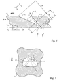
- the cooling bore 20 extends in a wall 10 from an inner surface 14 to an outer surface 12. At the outer surface 12 flows into the area in which the wall 10 is used Hot gas flow along.
- the inner surface 14 is a boundary surface Coolant chamber that contains pressurized cooling air.
- the cooling bore 20 On the On the cooling chamber side, the cooling bore 20 has a cylindrical feed section 22 whose cross-section at inlet 34 determines the amount of cooling air flowing through.
- the diffuser section 24 widens from the feed section 22 to the outlet 32 the outer surface 12. As best seen in Fig. 2, the Widening not only laterally, but also downstream.
- Figure 3 shows one perspective view of the cooling hole 20.
- the cooling holes to be provided component has a nominal wall thickness S should. As indicated schematically in FIG. 1, a wall thickness between S min (reference numeral 14a) and S max (reference numeral 14b) is permitted in the manufacture of the wall, the actual wall thickness S (reference numeral 14) thus lies between S min and S max .
- the feed section 22 has a circular cross section with a diameter d perpendicular to its axis 30.
- the length / of the feed section 22 is selected such that it still corresponds to its diameter at the minimum wall thickness of S min , ie is at least d . If the wall thickness is greater than S min , the feed section becomes correspondingly longer.
- the supply section 22 changes, but not the diffuser section 24, through the variation of the wall thickness. This design ensures a well-defined cooling air opening regardless of the manufacturing tolerances for any wall thickness.
- the boundary surfaces 40-46 of the diffuser section 24 have no curvature in the direction of flow of the cooling medium, that is to say along the axis 30. This makes it possible to cut these surfaces out of the outer surface 12 using a straight laser beam (FIG. 4). As can be seen in FIGS. 2 and 3, however, the boundary surfaces have pronounced fillets perpendicular to the axis 30.
- the upstream boundary surface 40 is elliptically rounded toward the axis 30. It merges into the side surfaces 44, 46 in a smooth curve.
- the downstream boundary surface 42 of the diffuser is essentially flat and smoothly merges into the side surfaces 44, 46 with a radius of curvature R 2 .
- a first step the shape of the hole is determined.
- the target wall thickness and the permitted tolerance of the wall thickness are taken into account.
- the diameter of the cylindrical feed section, its minimum length measured at its downstream edge and the angle which the hole axis encloses with the outer surface are determined.
- the shape and size of the exit surface are determined in the diffuser section, in particular the radius of the elliptical fillet on the upstream side and the radii of curvature with which the downstream edge merges into the side surfaces.
- the depth of the diffuser section results from the minimum permitted wall thickness S min and the minimum length of the cylindrical section.
- the opening ratio A r is the ratio of the diffuser exit area A out to the cylindrical entrance area A in , measured perpendicular to the hole axis.
- the coverage is the ratio of the average hole width Z m to the distance between the cooling holes P.
- a through hole is drilled in the wall, the one has a slightly smaller diameter than the cylindrical feed section.
- the laser beam is used with one of the respective drilling depths adapted cutting speed of the diffuser section cut out (Fig. 4).
- the laser steel 60 is focused with a lens 62, and along the contour to be cut out (reference numeral 64). Finally the cylindrical section cut out to the final contour.
- the control of the Laser beam is carried out via a CAD / CAM interface with a conventional CNC Machine.
- the described method can be used for both uncoated and metallic or ceramic-coated component walls can be used.
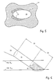
- Figure 5 shows the bottom view of the cooling chamber-side outlet 34 of a cooling hole 20.
- the areas 52 at the edge of the opening 34 were made by the laser drilling process additionally cut out. Due to the configuration of the These areas are kept small in the diffuser section.
- FIG. 6 the lower region of a cooling hole is shown in a perspective side view.
- the lines designated by the reference symbols 14a (S min ) and 14b (S max ) indicate the range of the positions of the inner surface which are possible due to the permissible tolerance of the wall thickness.
- S max the injured area 52 is largest.
- S min no injuries occur.
- FIG. 6 shows that, for reasons of cost, it is advantageous to tolerate a certain degree of injuries since the permissible wall thickness tolerance becomes very small when the supply section is required to be completely free of injuries.
Description
Die Erfindung betrifft ein Verfahren zur Herstellung einer nichtkreisförmigen Kühlbohrung, welche insbesondere zur Filmkühlung einer Wand in einer Heissgasumgebung dienen soll.The invention relates to a method for producing a non-circular cooling bore, which is intended in particular for film cooling of a wall in a hot gas environment.
Zur Steigerung der Leistung und des Wirkungsgrades werden bei heutigen Gasturbinenanlagen immer höhere Turbineneintrittstemperaturen angewendet. Um die Turbinenschaufeln vor den erhöhten Heissgastemperaturen zu schützen, müssen diese intensiv gekühlt werden. Bei entsprechend hohen Eintrittstemperaturen reicht eine rein konvektive Kühlung nicht mehr aus. Es wird daher vielfach die Methode der Filmkühlung eingesetzt. Dabei werden die Turbinenschaufeln durch einen Kühlfilm vor dem Heissgas geschützt. In die Schaufeln werden dazu Ausnehmungen, beispielsweise Bohrungen, eingebracht, durch die die Kühlluft ausgeblasen wird. To increase performance and efficiency in today's gas turbine plants ever higher turbine inlet temperatures applied. To the To protect turbine blades from the increased hot gas temperatures these are cooled intensively. With correspondingly high inlet temperatures Purely convective cooling is no longer sufficient. It is therefore often the Film cooling method used. The turbine blades are going through protected a cooling film from the hot gas. In the shovels become Recesses, for example holes, introduced through which the cooling air is blown out.
Um einen möglichst hohen Kühleffekt zu erreichen, muß die ausgeblasene Kühlluft möglichst schnell umgelenkt werden und schützend an der Profiloberfläche entlang strömen. Um auch die zwischen den Bohrungen liegenden Gebiete zu schützen, ist zudem eine schnelle seitliche Ausbreitung der Kühlluft erforderlich. Dies kann dadurch erreicht werden, daß die Kühlluftbohrungen einen Diffusor aufweisen, der aufgrund der seitlichen Aufweitung eine breitere Überdeckung der Oberfläche ermöglicht. Zur weiteren Verbesserung des Mischungsverhaltens werden Diffusorgeometrien verwendet, bei denen die Bohrung nicht nur seitlich, sondern zusätzlich auf der stromabwärts liegenden Seite der Bohrung aufgeweitet wird.In order to achieve the highest possible cooling effect, the blown-out cooling air must be redirected as quickly as possible and protectively along the profile surface stream. In order to protect the areas between the wells, too rapid lateral expansion of the cooling air is also required. This can can be achieved in that the cooling air holes have a diffuser, the due to the lateral expansion, a wider coverage of the surface allows. To further improve the mixing behavior Diffuser geometries are used in which the hole is not only on the side, but is additionally expanded on the downstream side of the bore.
Beispielsweise beschreibt die Druckschrift EP-B-228 338 eine gekühlte Wand mit einem Kühlmittelkanal, dessen Diffusorabschnitt sich zum Kühlmittelauslaß hin seitlich aufweitet und dessen stromabwärtige ebene Oberfläche von der Achse weg divergiert.For example, EP-B-228 338 describes a cooled wall a coolant duct, the diffuser section of which faces the coolant outlet widens sideways and its downstream flat surface away from the axis diverges.
Die Ausblaseraten bei diesen Diffusorgeometrien sind klein, so daß die Gefahr, daß die Kühlluft durch die Strömungsgrenzschicht hindurchtritt gering ist. Daher kann der Kühlwirkungsgrad gegenüber einer zylindrischen Bohrung erheblich gesteigert werden.The discharge rates for these diffuser geometries are small, so that there is a risk that the cooling air passing through the flow boundary layer is low. Therefore, the Cooling efficiency significantly increased compared to a cylindrical bore become.
Die Genauigkeit, mit der die mit Kühllöchern zu versehenden Werkstücke hergestellt werden müssen, stellt einen bedeutenden Kostenfaktor dar. Große Wandtolerenzen von bis zu 10% oder sogar von bis zu 20% erlauben, die Bauteile kostengünstig herzustellen. Andererseits führen die Schwankungen in der Wanddicke zu Variationen im Öffnungsverhältnis der Kühlbohrungen in Abhängigkeit von der Wandstärke. Die damit einhergehende ungleichmäßige Filmkühleffektivität führt entweder zur kostspieligen Überauslegung auf die schwächsten Punkte, oder zum Auftreten von überhitzten Stellen auf der Wandoberfläche, was die Lebensdauer des Bauteils drastisch reduziert.The accuracy with which the workpieces to be provided with cooling holes are manufactured must be an important cost factor. Large wall tolerances of up to 10% or even up to 20% allow the components to be inexpensive manufacture. On the other hand, the fluctuations in the wall thickness lead to Variations in the opening ratio of the cooling holes depending on the Wall thickness. The associated uneven film cooling effectiveness leads either for costly deliberation on the weakest points, or for Occurrence of overheated spots on the wall surface, reducing the life of the Component drastically reduced.
Die Herstellung solcher Löcher mit einem Erosionsverfahren, wie etwa in der Druckschrift US-A-4,197,443 beschrieben, hat neben den hohen Herstellungskosten den Nachteil, daß die Verwendung eines Erodierrechens bereits bei kleinen Oberflächentoleranzen zu stark unterschiedlichen Öffnungsverhältnissen der einzelnen Kühllöcher führt. Darüber hinaus kann das Erosionsverfahren nicht bei keramisch beschichteten Oberflächen eingesetzt werden, da diese elektrisch isolieren. Die Kühllöcher müssen in diesem Fall vor der Beschichtung hergestellt werden. Die nachfolgende Beschichtung legt in der Regel einen Teil der Diffusoröffnung zu, wodurch die Kühleigenschaften der Löcher beeinflusst werden. Es wird dann notwendig, in einem weiteren Verfahrensschritt das blockierende Material zu entfernen. Beispielsweise beschreibt die Druckschrift US-A-5,216,808 ein Verfahren zum Herstellen oder Reparieren eines Gasturbinenbauteils. Dabei wird nach Aufbringen einer Schutzschicht auf das Bauteil ein UV-Laserstrahl auf die Position eines Filmkühllochs gerichtet, um blockierendes Beschichtungsmaterial athermisch zu entfernen.The production of such holes with an erosion process, such as in the Document US-A-4,197,443 has besides the high manufacturing costs the disadvantage that the use of an EDM rake even with small Surface tolerances to very different opening conditions leads individual cooling holes. In addition, the erosion process cannot Ceramic coated surfaces can be used because they are electrical isolate. In this case, the cooling holes must be made before coating become. The subsequent coating usually lays part of the Diffuser opening too, which affects the cooling properties of the holes become. It then becomes necessary in a further process step to remove blocking material. For example, US-A-5,216,808 describes a method of making or repairing a Gas turbine component. After applying a protective layer on the Component directed a UV laser beam at the position of a film cooling hole to remove blocking coating material athermally.
Beim Laserbohren von Turbinenschaufeln werden überwiegend zwei
Bohrverfahren eingesetzt. Beim Percussionsbohren wird ein Loch mit relativ zum
Werkstück feststehender Strahlachse mit einer Reihe von Laserpulsen auf den
Solldurchmesser aufgebohrt. Mit diesem Verfahren lassen sich jedoch lediglich
zylindrische Löcher leicht herstellen.
Beim Trepannierbohrverfahren wird ein fein fokussierter Laserstrahl relativ zum
Werkstück bewegt und so das Loch ausgeschnitten. Bei der Herstellung von
Kühllöchern mit Diffusor mit einem Laserbohrverfahren tritt das Problem auf, dass
mit zunehmender Wandstärke auch die Länge des zylindrischen Lufteinlaufkanals
zunimmt. Dieser Einlaufkanal wird beim Ausschneiden des sich aufweitenden
Diffusors durch den Laserstrahl verletzt. Die entstehenden scharfkantigen
Verletzungen stellen ein schwerwiegendes Festigkeitsproblem dar. Darüber
hinaus verändert sich die Einlassöffnung und somit der Durchfluss durch die
Kühlbohrung. Aus diesem Grund kann das Trepannierverfahren für Kühllöcher mit
Diffusor nur bei kleinen Wandstärken eingesetzt werden.When drilling turbine blades by laser, two drilling methods are mainly used. Percussion drilling involves drilling a hole with a beam axis that is fixed relative to the workpiece with a series of laser pulses to the desired diameter. With this method, however, only cylindrical holes can be easily produced.
In the trepanning drilling process, a finely focused laser beam is moved relative to the workpiece, thus cutting out the hole. When producing cooling holes with a diffuser using a laser drilling process, the problem arises that with increasing wall thickness, the length of the cylindrical air inlet duct also increases. This inlet channel is injured when the expanding diffuser is cut out by the laser beam. The resulting sharp-edged injuries represent a serious strength problem. In addition, the inlet opening changes and thus the flow through the cooling hole. For this reason, the trepanning process for cooling holes with a diffuser can only be used with small wall thicknesses.
Die Druckschrift US-A-5,683,600 beschreibt ein Verfahren zur Herstellung kreisförmiger Kühllöchern mit sich diffusorartig erweiterndem, nichtkreisförmigem Austrittsquerschnitt in Gasturbinenkomponenten. Ein fokussierter Laserstrahl von nichtkreisförmigem Querschnitt wird unter einem spitzen Einfallwinkel auf die Bauteilwand gerichtet, um zunächst die Diffusoröffnung auszubilden. Anschliessend wird die Herstellung des zylindrischen Eingangsbereichs des Kühllochs durch den ausgebildeten Diffusor hindurch fortgesetzt bis zur kompletten Fertigstellung der Durchgangsbohrung. Da keine Relativbewegung zwischen Laserstrahl und Bauteil stattfindet, werden Grösse und Form der Diffusoröffnung durch Querschnittsform und Einfallwinkel des Laserstahls sowie die Anordnung des Brennpunkts bestimmt. Hierbei ist nachteilig, dass die Bereitstellung eines nichtkreisförmigen Laserstrahls einen zusätzlichen apparativen Aufwand erfordert und die Vielfalt und Flexibilität der möglichen Querschnittsformen einschränkt.US-A-5,683,600 describes a method of manufacture circular cooling holes with diffuser-like, non-circular Outlet cross section in gas turbine components. A focused laser beam from non-circular cross-section is at an acute angle of incidence on the Component wall directed to first form the diffuser opening. The cylindrical entrance area of the Cooling holes continued through the trained diffuser to complete completion of the through hole. Because no relative movement between the laser beam and the component takes place, size and shape of the Diffuser opening through cross-sectional shape and angle of incidence of the laser steel as well determines the location of the focus. The disadvantage here is that the Providing a non-circular laser beam an additional requires equipment and the variety and flexibility of the possible Cross-sectional shapes restricted.
Die Druckschrift US-A-5,609,779 wird als nächesliegender Stand der Technik angesehen und offenbart ein Verfahren zum Ausbilden einer Öffnung in einer metallischen Bauteilwand, wobei die Öffnung einen sich aufweitenden Diffusor aufweist. Der nichtkreisförmige Diffusor wird hergestellt, indem ein Nd:YAG-Laserstrahl innerhalb weniger Laserpulse von der Mittellinie der Öffnung beschleunigt zur Kante des Diffusors geführt wird. Pulsrate und Leistung des Lasers sind so gewählt, dass das Metall durch den Laserstrahl verdampft. Nachteilig ist, dass die entstehenden Diffusoren bei einem solchen Verfahren sehr unterschiedlich ausfallen. Eine gleichmässige Effektivität der Kühlöffnungen ist jedoch wegen der engen Auslegung der Bauteile in modernen Gasturbinen unerlässlich.US-A-5,609,779 is considered to be the closest prior art and discloses a method of forming one Opening in a metallic component wall, the opening being one has widening diffuser. The non-circular diffuser is made by placing an Nd: YAG laser beam within a few laser pulses from the center line the opening is accelerated to the edge of the diffuser. Pulse rate and Power of the laser are chosen so that the metal by the laser beam evaporated. The disadvantage is that the resulting diffusers in such a Procedures are very different. A uniform effectiveness of However, cooling vents are modern due to the narrow design of the components Gas turbines essential.
Der Erfindung liegt die Aufgabe zugrunde, ein Verfahren bereitzustellen, mit dem eine Kühlbohrung in einer Wand kostengünstig, genau und hochflexibel ausgebildet werden kann. Insbesondere soll das Verfahren es erlauben, die Kühlbohrung unabhängig von den Herstellungstoleranzen der Wandstärke auszubilden und soll für alle Wandstärken geeignet sein. The invention has for its object to provide a method with which a cooling hole in a wall inexpensive, accurate and highly flexible can be trained. In particular, the method should allow the Cooling hole regardless of the manufacturing tolerances of the wall thickness train and should be suitable for all wall thicknesses.
Diese Aufgabe wird durch ein Verfahren zum Ausbilden einer Kühlbohrung nach
Anspruch 1 gelöst. Vorteilhafte Ausführungsformen geben die abhängigen
Ansprüche wieder.This object is accomplished by a method of forming a
Das erfindungsgemässe Verfahren zum Ausbilden einer Kühlbohrung in einer
Wand eines Werkstücks, wobei die Kühlbohrung in Strömungsreihenfolge einen
Zuführabschnitt mit konstanter Querschnittsfläche und einen sich zu einem
Auslass an einer äusseren Oberfläche der Wand hin aufweitenden
Diffusorabschnitt aufweist, umfasst folgende Verfahrensschritte:
Die Erfindung beruht demnach auf dem Gedanken, den Diffusorabschnitt einer Kühlbohrung so mit einem Bohrstrahl auszuschneiden, dass der Zuführabschnitt nicht oder nur wenig verletzt wird, wodurch die Kühlbohrung eine hohe Festigkeit erhält. Die Strömung des Kühlmittels durch die Kühlbohrung im Betrieb legt eine Strömungsrichtung in der Kühlbohrung fest. Form und Größe der Querschnittsfläche des Zuführabschnitt bestimmen die durchströmende Menge des Kühlmittels. Das erfindungsgemäße Verfahren bietet den Vorteil, daß die Kühlbohrung durch die Verwendung eines Bohrstrahlverfahrens, insbesondere eines Laserbohrverfahrens, genau und flexibel geschnitten werden kann. Das Verfahren ist für unbeschichtete wie für metallisch oder keramisch beschichtete Bauteile geeignet. Im letzeren Fall können die Kühlbohrungen nach der Beschichtung in einem einzigen Arbeitsgang hergestellt werden. Es entfällt die Notwendigkeit, die Löcher vor der Beschichtung zu bohren und nach der Beschichtung die blockierten Öffnungen wieder freizulegen. Verletzungen des Zuführabschnitts werden dadurch minimiert, daß der Bohrstrahl beim Ausschneiden des Diffusorabschnitts im wesentlichen innerhalb der Querschnittsfläche des Zuführabschnitts bleibt.The invention is therefore based on the idea of a diffuser section Cut the cooling hole with a drilling jet so that the feed section not or only slightly injured, which makes the cooling hole high strength receives. The flow of the coolant through the cooling hole during operation sets one Flow direction fixed in the cooling hole. Shape and size of the cross-sectional area of the supply section determine the amount of coolant flowing through. The The inventive method has the advantage that the cooling hole through the Use of a drilling jet method, in particular a laser drilling method, can be cut precisely and flexibly. The process is for uncoated as suitable for metallic or ceramic coated components. In the latter case the cooling holes can be coated in a single operation after coating getting produced. There is no need to pre-coat the holes to drill and uncover the blocked openings after coating. Injuries to the feed section are minimized in that the drilling jet when cutting out the diffuser section substantially within the Cross-sectional area of the feed section remains.
Bevorzugt wird als Strahlbohrverfahren ein Laserbohrverfahren, insbesondere ein gepulstes Laserbohrverfahren verwendet. Bevorzugt kommt dabei ein gepulster Nd:YAG-Laser oder ein gepulster CO2-Laser zum Einsatz. Jedoch liegt auch die Verwendung anderer Bohrstrahlen, etwa eines Wasserstrahls im Rahmen der Erfindung.A laser drilling method, in particular a pulsed laser drilling method, is preferably used as the beam drilling method. A pulsed Nd: YAG laser or a pulsed CO 2 laser is preferably used. However, the use of other drilling jets, such as a water jet, is also within the scope of the invention.
Vorzugsweise wird in Schritt D der Diffusorabschnitt gerade ausgeschnitten, so daß die Begrenzungsflächen des Diffusorabschnitts in Strömungsrichtung der Kühlbohrung keine Krümmung aufweisen. Die Festigkeit der Kühlbohrung kann weiter erhöht werden, indem in einem weiteren Schritt E der Zuführabschnitt auf Endkontur ausgeschnitten wird. Ein solcher Schritte steigert die Qualität des Zuführabschnitts und trägt dadurch zur Güte und Festigkeit der gesamten Kühlbohrung bei.In step D, the diffuser section is preferably cut out straight, so that the boundary surfaces of the diffuser section in the flow direction of the Cooling hole have no curvature. The strength of the cooling hole can can be further increased by opening the feed section in a further step E. Final contour is cut out. Such a step increases the quality of the Feed section and thereby contributes to the quality and strength of the whole Cooling hole at.
Für den Zuführabschnitt wird in Schritt A bevorzugt ein elliptischer, besonders bevorzugt kreisförmiger Querschnitt gewählt. Der Querschnitt des Zuführabschnitts wird dabei senkrecht zur Achse der Kühlbohrung genommen.In step A, an elliptical, particularly, is preferred for the feed section preferably selected circular cross section. The cross section of the feed section is taken perpendicular to the axis of the cooling hole.
Die Achse des Zuführabschnitts schneidet die äußere Oberfläche vorteilhaft unter einem Winkel α < 90° und definiert dadurch eine Kipprichtung der Kühlbohrung. Die Filmkühleffektivität der Kühlbohrung läßt sich dadurch steigern, daß die Austrittsfläche des Diffusorabschnitts so gewählt wird, daß sich der Diffusorabschnitt zur äußeren Oberfläche der Wand hin zumindest in Kipprichtung der Achse aufweitet. Die der Kipprichtung abgewandte Begrenzungsfläche des Diffusorabschnitts wird mit Vorteil zur Achse hin abgerundet, insbesondere elliptisch abgerundet gewählt. Dadurch erhöht sich einerseits die Stabilität der Kühlbohrung gegen äußere Einwirkungen, andererseits führt die Ausrundung zu einer weiteren signifikanten Verringerung der Verletzungen des Zuführabschnitts beim Ausschneiden des Diffusorteils.The axis of the feed section advantageously undercuts the outer surface an angle α <90 ° and thereby defines a tilting direction of the cooling hole. The Film cooling effectiveness of the cooling hole can be increased in that the Exit surface of the diffuser section is chosen so that the diffuser section towards the outer surface of the wall at least in the tilting direction of the axis expands. The boundary surface of the The diffuser section is advantageously rounded off towards the axis, in particular elliptically rounded off. On the one hand, this increases the stability of the cooling hole against external influences, on the other hand the rounding leads to another significant reduction in injuries to the feeding section in the Cut out the diffuser part.
Die in Kipprichtung liegende Auslaßkante des Diffusorabschnitts wird zweckmäßig so gewählt, daß sie im wesentlichen gerade ist und an ihren Enden in einer glatten Kurve in die Seitenkanten des Auslasses übergeht. Besonders zweckmäßig ist es, für den Zuführabschnitt einen kreisförmiger Querschnitt mit Radius R zu wählen und die in Kipprichtung liegende Auslaßkante des Diffusorabschnitts so zu wählen, daß sie in die Seitenkanten des Auslasses mit einem Krümmungsradius größer als R übergeht.The outlet edge of the diffuser section lying in the tilting direction is expediently chosen such that it is essentially straight and at its ends merges into the side edges of the outlet in a smooth curve. It is particularly expedient to choose a circular cross section with radius R for the feed section and to select the outlet edge of the diffuser section lying in the tilting direction so that it merges with the side edges of the outlet with a radius of curvature greater than R.
Eine weitere Steigerung der Kühleffektivität läßt sich erreichen, wenn die Austrittsfläche des Diffusorabschnitts so gewählt wird, daß sich der Diffusorabschnitt zur äußeren Oberfläche der Wand hin seitlich aufweitet.A further increase in cooling effectiveness can be achieved if the Exit surface of the diffuser section is chosen so that the diffuser section widens laterally towards the outer surface of the wall.
Vorteilhaft wird die äußere Oberfläche der Wand vor dem Erzeugen der Durchgangsbohrung im Schritt C zumindest teilweise mit einer Schutzschicht, insbesondere einer keramischen Schutzschicht überzogen.The outer surface of the wall is advantageous before generating the Through hole in step C at least partially with a protective layer, in particular covered with a ceramic protective layer.
Die erfindungsgemäße nichtkreisförmige Kühlbohrung in einer Wand eines Werkstücks umfaßt einen Zuführabschnitt mit konstanter Querschnittsfläche und einen Diffusorabschnitt, der sich zu einem Auslaß an einer ersten Oberfläche der Wand hin aufweitet. Dabei umfaßt der Zuführabschnitt einen in eine zweite Oberfläche der Wand austretenden Eingangsabschnitt und einen an den Diffusorabschnitt angrenzenden Zuleitungsabschnitt, wobei die Länge des Eingangsabschnitts an der Achse höchstens 40% der Länge des Zuführabschnitts beträgt. Weiter sind die Begrenzungsflächen des Diffusorabschnitts in Strömungsrichtung der Kühlbohrung gerade und die Tangenten an die Begrenzungsflächen durch die Achse verlaufen im Inneren des Zuleitungsabschnitts und schneiden den Zuführabschnitt höchstens in dem Eingangsabschnitt. The non-circular cooling hole according to the invention in a wall of a Workpiece comprises a feed section with a constant cross-sectional area and a diffuser section that extends to an outlet on a first surface of the Widening the wall. The feed section comprises one in a second Surface of the wall emerging entrance section and one to the Diffuser section adjacent lead section, the length of the Entry section on the axis at most 40% of the length of the feed section is. The boundary surfaces of the diffuser section are shown in FIG Flow direction of the cooling hole straight and the tangents to the Boundary surfaces through the axis run inside the feed section and cut the feed section at most in the input section.
Eine solche nichtkreisförmige Kühlbohrung kann aufgrund ihrer Auslegung leicht mit einem Laserbohrverfahren hergestellt werden. Die relativen Größen des Eingangsabschnitts und des Zuleitungsabschnitts stellen sicher, daß der Zuführabschnitt nicht durch den Laserstrahl nicht zu stark verletzt wird. Die Bedingung an die Tangenten an die Begrenzungsflächen bewirkt, daß bei geeigneter Strahlführung ein gerader Laserstrahl den Zuführabschnitt beim Ausschneiden des Diffusors höchstens im Bereich des Eingangsabschnitts verletzt, ansonsten aber ohne einen Teil der Bauteilwand zu treffen, durch die Öffnung in der zweiten Oberfläche geht.Such a non-circular cooling hole can easily with due to its design a laser drilling process. The relative sizes of the Input section and the feed section ensure that the Feed section is not injured too much by the laser beam. The Condition on the tangents to the boundary surfaces causes that at suitable beam guidance a straight laser beam at the feed section Cutting the diffuser injured at most in the area of the entrance section, otherwise but without hitting part of the component wall, through the opening in the second surface goes.
Zweckmäßig schneidet die Achse der Kühlbohrung die erste Oberfläche der Wand unter einem Winkel zwischen 10° und 60°, bevorzugt unter einem Winkel zwischen 15° und 50°, besonders bevorzugt unter einem Winkel zwischen 25° und 35°. Die Kühleffektivität der Kühlbohrung läßt sich weiter steigern wenn sich der Diffusorabschnitt zur ersten Oberfläche der Wand hin zumindest in Kipprichtung der Achse aufweitet oder wenn er sich zur ersten Oberfläche der Wand hin seitlich aufweitet. Besonders deutlich läßt sich die Effektivität steigern, wenn seitliche und stromabwärtige Aufweitung kombiniert werden.The axis of the cooling hole expediently intersects the first surface of the wall at an angle between 10 ° and 60 °, preferably at an angle between 15 ° and 50 °, particularly preferably at an angle between 25 ° and 35 °. The Cooling effectiveness of the cooling hole can be further increased if the Diffuser section towards the first surface of the wall at least in the tilting direction of the Axis expands or if it laterally to the first surface of the wall expands. The effectiveness can be increased particularly clearly if lateral and downstream expansion can be combined.
Mit Vorteil ist die der Kipprichtung abgewandte Begrenzungsfläche des Diffusorabschnitts zur Achse hin gerundet, bevorzugt elliptisch gerundet. Dadurch erhöht sich einerseits die Stabilität der Kühlbohrung gegen äußere Einwirkungen, andererseits führt die Ausrundung zu einer weiteren signifikanten Verringerung der Verletzungen des Zuführabschnitts beim Ausschneiden des Diffusorteils. Die der Kipprichtung zugewandte Begrenzungsfläche des Diffusorabschnitts ist bevorzugt im wesentlichen eben und geht in einer glatten Kurve in die Seitenflächen über.Advantageously, the boundary surface facing away from the tilting direction of the Diffuser section rounded towards the axis, preferably elliptically rounded. Thereby on the one hand increases the stability of the cooling hole against external influences, on the other hand, the rounding leads to a further significant reduction in the Injuries to the feed section when cutting out the diffuser part. The the Limiting surface of the diffuser section facing the tilting direction is preferably in essentially flat and merges into the side surfaces in a smooth curve.
Der Zuführabschnitt weist bevorzugt einen kreisförmigen Querschnitt mit Radius R auf. Die Länge des Zuführabschnitts ist dann zweckmäßig so gewählt, daß sie seiner kürzesten Begrenzungsfläche mindestens 2R beträgt. Dadurch ist ein wohldefinierter zylinderförmiger Öffnungsbereich festgelegt, durch den die im Betrieb einströmende Kühlmittelmenge bestimmt ist.The feed section preferably has a circular cross section with radius R. The length of the feed section is then expediently chosen so that its shortest boundary surface is at least 2R . This defines a well-defined cylindrical opening area, which determines the amount of coolant flowing in during operation.
In einer Ausgestaltung der Erfindung ist die erste Oberfläche der Wand zumindest teilweise mit einer Schutzschicht, insbesondere einer keramischen Schutzschicht überzogen. In einer weiteren Ausgestaltung ist die Wand die äußere Wand eines Hohlprofilkörpers, insbesondere einer Gasturbinenschaufel.In one embodiment of the invention, the first surface of the wall is at least partly with a protective layer, in particular a ceramic protective layer overdrawn. In a further embodiment, the wall is the outer wall of a Hollow profile body, in particular a gas turbine blade.
Die Erfindung soll nachfolgend anhand von Ausführungsbeispielen im Zusammenhang mit den Zeichnungen näher erläutert werden. Es zeigen
- Fig. 1
- einen Querschnitt durch eine Wand mit einer erfindungsgemäßen Kühlbohrung;
- Fig. 2
- eine Teilansicht der Wand in Richtung 2-2 von Fig. 1;
- Fig. 3
- eine perspektivische Ansicht einer erfindungsgemäßen Kühlbohrung;
- Fig. 4
- eine schematische Darstellung, die das Ausschneiden einer Kühlbohrung mit einem Laserstrahl entsprechend einem Ausführungsbeispiel der Erfindung illustriert;
- Fig. 5
- einen Unteransicht einer Wand in Richtung 5-5 von Fig. 1;
- Fig. 6
- eine perspektivische Teilseitenansicht der Wand von Fig. 5;
- Fig. 1
- a cross section through a wall with a cooling hole according to the invention;
- Fig. 2
- a partial view of the wall in the direction 2-2 of Fig. 1;
- Fig. 3
- a perspective view of a cooling hole according to the invention;
- Fig. 4
- is a schematic representation illustrating the cutting of a cooling hole with a laser beam according to an embodiment of the invention;
- Fig. 5
- a bottom view of a wall in the direction 5-5 of Fig. 1;
- Fig. 6
- a partial perspective side view of the wall of Fig. 5;
Es sind nur die für das Verständnis der Erfindung wesentlichen Elemente gezeigt. Nicht gezeigt ist beispielsweise der vollständige Hohlprofilkörper der Turbinenschaufel und die gesamte Anordnung der Kühlbohrungen. Die Strömungsrichtung des Arbeitsmittels ist mit Pfeilen bezeichnet. Übereinstimmende Elemente sind in allen Figuren mit demselben Bezugszeichen bezeichnet.Only the elements essential for understanding the invention are shown. For example, the complete hollow profile body is not shown in FIG Turbine blade and the entire arrangement of the cooling holes. The The direction of flow of the working fluid is indicated by arrows. Matching Elements are designated by the same reference numerals in all figures.
Ein Ausführungsbeispiel der Erfindung wird mit Bezug auf die in den Figuren 1 bis 3
gezeigten Kühlbohrung erläutert. Die Kühlbohrung 20 in einer Wand 10 erstreckt
sich von einer inneren Oberfläche 14 zu einer äußeren Oberfläche 12. An der
äußeren Oberfläche 12 strömt in der Einsatzumgebung der Wand 10 ein
Heißgasstrom entlang. Die innere Oberfläche 14 ist Begrenzungsfläche einer
Kühlmittelkammer, die unter Druck stehende Kühlluft enthält. Auf der
Kühlkammerseite weist die Kühlbohrung 20 einen zylindrischen Zuführabschnitt 22
auf, dessen Querschnitt am Einlaß 34 die durchströmende Kühlluftmenge bestimmt.
Der Diffusorabschnitt 24 weitet sich vom Zuführabschnitt 22 zu dem Auslaß 32 an
der äußeren Oberfläche 12 hin auf. Wie am besten in Fig. 2 zu sehen, erfolgt die
Aufweitung nicht nur seitlich, sondern auch stromab. Figur 3 zeigt eine
perspektivische Ansicht der Kühlbohrung 20.An embodiment of the invention will be described with reference to that in FIGS
cooling hole shown explained. The cooling bore 20 extends in a
Das mit Kühlbohrungen zu versehende Bauteil hat eine Sollwandstärke Ssoll. Wie in Figur 1 schematisch angedeutet, wird bei der Herstellung der Wand eine Wandstärke zwischen Smin (Bezugszeichen 14a) und Smax (Bezugszeichen 14b) zugelassen, die tatsächliche Wandstärke S (Bezugszeichen 14) liegt also zwischen Smin und Smax.The cooling holes to be provided component has a nominal wall thickness S should. As indicated schematically in FIG. 1, a wall thickness between S min (reference numeral 14a) and S max (reference numeral 14b) is permitted in the manufacture of the wall, the actual wall thickness S (reference numeral 14) thus lies between S min and S max .
Der Zuführabschnitt 22 weist senkrecht zu seiner Achse 30 einen kreisförmigen
Querschnitt mit Durchmesser d auf. Die Länge / des Zuführabschnitts 22 ist so
gewählt, daß sie bei der minimalen Wandstärke von Smin noch seinem Durchmesser
entspricht, also mindestens d beträgt. Ist die Wandstärke größer als Smin, wird der
Zuführabschnitt entsprechend länger. Durch die Variation der Wandstärke ändert
sich also der Zuführabschnitt 22, nicht jedoch der Diffusorabschnitt 24. Durch diese
Auslegung ist unabhängig von den Herstellungstoleranzen bei jeder Wanddicke ein
gute definierter Kühlluftöffnung gewährleistet.The
Die Begrenzungsflächen 40-46 des Diffusorabschnitts 24 weisen in
Strömungsrichtung des Kühlmediums, also entlang der Achse 30 keine Krümmung
auf. Dadurch ist es möglich, diese Flächen durch einen geraden Laserstrahl von der
äußeren Oberfläche 12 her auszuschneiden (Fig. 4). Wie in Figuren 2 und 3 zu
sehen, weisen die Begrenzungsflächen jedoch senkrecht zu der Achse 30
ausgeprägte Ausrundungen auf. Die stromaufwärtige Begrenzungsfläche 40 ist in
diesem Ausführungsbeispiel elliptisch zur Achse 30 hin gerundet. Sie geht in einer
glatten Kurve in die Seitenflächen 44, 46 über. Die stromabwärtige
Begrenzungsfläche 42 des Diffusors ist im wesentlichen eben und geht mit einem
Krümmungsradius R2 glatt in die Seitenflächen 44,46 über. Dabei ist R2 größer
gewählt als der Radius des zylindrischen Abschnitts R=d/2. Im Ausführungsbeispiel
ist R2 um 50% größer als der Radius des Zylinderabschnitts 22. The boundary surfaces 40-46 of the
Diese Maßnahmen führen dazu, daß die Tangenten 50 an die Begrenzungsflächen
40-46 durch die Achse 30 den zylindrischen Zuführabschnitt höchstens in einem
kleinen Eingangsabschnitt 28 schneiden. Der Zuleitungsabschnitt 26 wird von den
Tangenten nicht getroffen. Eine solche Kühlbohrung kann somit sehr gut mit einem
Laserstrahl ausgeschnitten werden, da der Laserstrahl wie die Tangenten 50 den
Zuführabschnitt 22 beim Ausschneiden höchstens in dem Eingangsabschnitt 28
verletzt. In der Regel geht der Laserstrahl ohne Schaden zu verursachen durch die
Öffnung 34 des Zuführabschnitts.These measures cause the
Ein erfindungsgemäßes Herstellungsverfahren einer Kühlbohrung wie in Figuren 1 bis 3 gezeigt, wird im folgenden beschrieben: In einem ersten Schritt wird die Gestalt des Lochs festgelegt. Dabei gehen Sollwandstärke und erlaubte Toleranz der Wandstärke mit ein. Festgelegt werden der Durchmesser des zylindrischen Zuführabschnitts, seine Mindestlänge gemessen an seiner stromabwärtigen Kante und der Winkel den die Lochachse mit der äußeren Oberfläche einschließt. Beim Diffusorabschnitt werden Form und Größe der Austrittsfläche festgelegt, insbesondere die Halbmesser der elliptischen Ausrundung an der stromaufwärtigen Seite und die Krümmungsradien, mit der die stromabwärtige Kante in die Seitenflächen übergeht. Aus der minimal erlaubten Wandstärke Smin und der Mindestlänge des zylindrischen Abschnitts ergibt sich die Tiefe des Diffusorabschnitts.An inventive method of manufacturing a cooling hole as shown in Figures 1 to 3 is described below: In a first step, the shape of the hole is determined. The target wall thickness and the permitted tolerance of the wall thickness are taken into account. The diameter of the cylindrical feed section, its minimum length measured at its downstream edge and the angle which the hole axis encloses with the outer surface are determined. The shape and size of the exit surface are determined in the diffuser section, in particular the radius of the elliptical fillet on the upstream side and the radii of curvature with which the downstream edge merges into the side surfaces. The depth of the diffuser section results from the minimum permitted wall thickness S min and the minimum length of the cylindrical section.
Diese Werte werden für die unterschiedlichen Sollwandstärken so festgelegt, daß sich die aerodynamischen Parameter der Kühlbohrungen und damit die Kühleffektivität nicht verändern. Dies geschieht dadurch, daß das Öffnungsverhältnis Ar, die mittlere Lochbreite Zm und die Bedeckung Zm/P konstant gehalten werden. Dabei ist das Öffnungsverhältnis Ar das Verhältnis der Diffusoraustrittsfläche Aout zur zylindrischen Eintrittsfläche Ain, gemessen jeweils senkrecht zur Lochachse. Die Bedeckung ergibt sich als Verhältnis der mittleren Lochbreite Zm zum Abstand der Kühlbohrungen P.These values are set for the different target wall thicknesses so that the aerodynamic parameters of the cooling holes and thus the cooling effectiveness do not change. This is done by keeping the opening ratio A r , the average hole width Z m and the coverage Z m / P constant. The opening ratio A r is the ratio of the diffuser exit area A out to the cylindrical entrance area A in , measured perpendicular to the hole axis. The coverage is the ratio of the average hole width Z m to the distance between the cooling holes P.
In einem nächsten Schritt wird in die Wand ein Durchgangsloch gebohrt, das einen
etwas kleineren Durchmesser als der zylindrische Zuführabschnitt aufweist.
Anschließend wird mit dem Laserstrahl mit einer der jeweiligen Bohrtiefe
angepaßten Schnittgeschwindigkeit der Diffusorabschnitt ausgeschnitten (Fig. 4).
Dabei wird der Laserstahl 60 mit einer Linse 62 fokussiert, und entlang der
auszuschneidenden Kontur geführt (Bezugszeichen 64). Zuletzt wird der
zylindrische Abschnitt auf die Endkontur ausgeschnitten. Die Steuerung des
Laserstrahls erfolgt über eine CAD/CAM Schnittstelle mit einer üblichen CNC
Maschine.In a next step, a through hole is drilled in the wall, the one
has a slightly smaller diameter than the cylindrical feed section.
Then the laser beam is used with one of the respective drilling depths
adapted cutting speed of the diffuser section cut out (Fig. 4).
The
Das beschriebene Verfahren kann sowohl für unbeschichtete als auch für metallisch oder keramisch beschichtete Bauteilwände angewandt werden.The described method can be used for both uncoated and metallic or ceramic-coated component walls can be used.
Figur 5 zeigt in Unteransicht den kühlkammerseitigen Auslaß 34 einer Kühlbohrung
20. Die Bereiche 52 am Rand der Öffnung 34 wurden durch den Laserbohrprozess
zusätzlich ausgeschnitten. Durch die erfindungsgemäße Ausgestaltung des
Diffusorabschnitts sind diese Bereiche klein gehalten.Figure 5 shows the bottom view of the cooling chamber-
In Figur 6 ist der untere Bereich einer Kühlbohrung in perspektivischer
Seitenansicht gezeigt. Die mit den Bezugszeichen 14a (Smin)und 14b (Smax)
bezeichneten Linien geben den Bereich der durch die zulässige Toleranz der
Wandstärke möglichen Positionen der inneren Oberfläche an. Bei einer Wandstärke
von Smax ist der verletzte Bereich 52 am größten. Bei einer Wandstärke Smin treten
keine Verletzungen auf. Figur 6 zeigt, daß es aus Kostengründen vorteilhaft ist, ein
gewisses Maß an Verletzungen zu tolerieren, da bei einer Forderung nach völliger
Verletzungsfreiheit des Zuführabschnitts die zulässige Wandstärkentoleranz sehr
klein wird. In Figure 6, the lower region of a cooling hole is shown in a perspective side view. The lines designated by the
- 1010
- Wandwall
- 1212
- äußere Oberflächeouter surface
- 14,14a,14b14,14a, 14b
- innere Oberflächeinner surface
- 2020
- FilmkühllochFilm cooling hole
- 2222
- Zuführabschnittfeeding
- 2424
- Diffusorabschnittdiffuser section
- 2626
- Zuleitungsabschnittlead portion
- 2828
- Eingangsabschnittinput section
- 3030
- Achse des FilmkühllochsAxis of the film cooling hole
- 3232
- Auslaß des DiffusorabschnittsOutlet of the diffuser section
- 3434
- Einlaß des ZuführabschnittsInlet of the feed section
- 4040
- stromaufwärtige Begrenzungsflächeupstream boundary surface
- 4242
- stromabwärtige Begrenzungsflächedownstream boundary surface
- 44,4644.46
- Seitenflächen des DiffusorabschnittsSide surfaces of the diffuser section
- 5050
- Tangenten an die BegrenzungsflächenTangents to the boundary surfaces
- 5252
- verletzte Bereicheinjured areas
- 6060
- Laserstrahllaser beam
- 6262
- Linselens
- 6464
- auszuschneidende Konturcontour to be cut out
Claims (12)
- Method for forming a cooling bore with the aid of a beam- or jet-drilling method in a wall of a workpiece, the cooling bore, in the flow sequence, having a feed section of constant cross-sectional area and a diffuser section widening towards an outlet at an outer surface of the wall, comprising the following steps:A) Selecting the shape and size of the cross-sectional area and an axis of the feed section;B) Selecting the depth of the diffuser section and the shape and size of its discharge area at the outlet;C) Producing a throughbore having a cross-sectional area which lies within the cross-sectional area, selected in step A, of the feed section;D) Cutting out the diffuser section with a beam- or jet-drilling method, characterized in that the drilling beam or jet is directed relative to the workpiece along the contour to be cut out in such a way that, in the region of the feed section, it remains essentially within the cross-sectional area selected in step A.
- Method according to Claim 1, characterized in that the beam- or jet-drilling method used in step D is a laser-drilling method, in particular a pulsed laser-drilling method.
- Method according to Claim 1, characterized in that the diffuser section is cut straight in step D, so that the boundary surfaces of the diffuser section have no curvature in the direction of flow of the cooling bore.
- Method according to Claim 1, characterized in that the feed section is cut out to the final contour in a step E.
- Method according to Claim 1, characterized in that an elliptical, in particular circular, cross section is selected in step A.
- Method according to Claim 1, characterized in that, in step A, the axis is selected in such a way that it intersects the surface of the wall at an angle of less than 90°.
- Method according to Claim 6, characterized in that, in step B, the discharge area of the diffuser section is selected in such a way that the diffuser section widens towards the outer surface of the wall at least in the direction of tilt of the axis.
- Method according to Claim 7, characterized in that, in step B, the discharge area of the diffuser section is selected in such a way that that boundary surface of the diffuser section which lies in the opposite direction to the direction of tilt is rounded off towards the axis, in particular elliptically.
- Method according to Claim 7 or 8, characterized in that, in step B, the discharge area of the diffuser section is selected in such a way that that outlet edge of the diffuser section which lies in the direction of tilt is essentially straight and merges at its ends in a smooth curve into the side edges of the outlet.
- Method according to Claim 9, characterized in that, in step A, a circular cross section of radius R is selected for the feed section, and, in step B, that outlet edge of the diffuser section which lies in the direction of tilt is selected in such a way that it merges into the side edges of the outlet with a radius of curvature greater than R.
- Method according to Claim 1, characterized in that, in step B, the discharge area of the diffuser section is selected in such a way that the diffuser section widens laterally towards the outer surface of the wall.
- Method according to Claim 1, characterized in that the outer surface of the wall, before step C, is covered at least partly with a protective coating, in particular a ceramic protective coating.
Priority Applications (6)
| Application Number | Priority Date | Filing Date | Title |
|---|---|---|---|
| EP98810252A EP0950463B1 (en) | 1998-03-23 | 1998-03-23 | Non-circular cooling hole and method of manufacturing the same |
| DE59802893T DE59802893D1 (en) | 1998-03-23 | 1998-03-23 | Non-circular cooling hole and method of manufacturing the same |
| CA002266137A CA2266137A1 (en) | 1998-03-23 | 1999-03-18 | Noncircular cooling bore and method of producing it |
| US09/273,756 US6307175B1 (en) | 1998-03-23 | 1999-03-22 | Method of producing a noncircular cooling bore |
| JP11078678A JP2000064806A (en) | 1998-03-23 | 1999-03-23 | Noncircular cooling hole and forming method thereof |
| CNB991058569A CN1135148C (en) | 1998-03-23 | 1999-03-23 | Non-circular shape cooling hole and processing method |
Applications Claiming Priority (1)
| Application Number | Priority Date | Filing Date | Title |
|---|---|---|---|
| EP98810252A EP0950463B1 (en) | 1998-03-23 | 1998-03-23 | Non-circular cooling hole and method of manufacturing the same |
Publications (2)
| Publication Number | Publication Date |
|---|---|
| EP0950463A1 EP0950463A1 (en) | 1999-10-20 |
| EP0950463B1 true EP0950463B1 (en) | 2002-01-23 |
Family
ID=8236007
Family Applications (1)
| Application Number | Title | Priority Date | Filing Date |
|---|---|---|---|
| EP98810252A Expired - Lifetime EP0950463B1 (en) | 1998-03-23 | 1998-03-23 | Non-circular cooling hole and method of manufacturing the same |
Country Status (6)
| Country | Link |
|---|---|
| US (1) | US6307175B1 (en) |
| EP (1) | EP0950463B1 (en) |
| JP (1) | JP2000064806A (en) |
| CN (1) | CN1135148C (en) |
| CA (1) | CA2266137A1 (en) |
| DE (1) | DE59802893D1 (en) |
Cited By (1)
| Publication number | Priority date | Publication date | Assignee | Title |
|---|---|---|---|---|
| EP2292372A2 (en) | 2009-08-17 | 2011-03-09 | Siemens Aktiengesellschaft | Method for making a hole using different laser positions |
Families Citing this family (79)
| Publication number | Priority date | Publication date | Assignee | Title |
|---|---|---|---|---|
| DE19960797C1 (en) * | 1999-12-16 | 2001-09-13 | Mtu Aero Engines Gmbh | Method for producing an opening in a metallic component |
| GB0001399D0 (en) * | 2000-01-22 | 2000-03-08 | Rolls Royce Plc | An aerofoil for an axial flow turbomachine |
| US6801936B1 (en) * | 2000-04-07 | 2004-10-05 | Arif Diwan | Systems and methods for generating customized bundles of information |
| US6573474B1 (en) * | 2000-10-18 | 2003-06-03 | Chromalloy Gas Turbine Corporation | Process for drilling holes through a thermal barrier coating |
| DE10054853A1 (en) * | 2000-11-06 | 2002-08-01 | Bosch Gmbh Robert | Making cleanly-cut fuel injector micro-perforation by circumscribing with laser focus, employs nanosecond-pulsed laser beam |
| US6420677B1 (en) * | 2000-12-20 | 2002-07-16 | Chromalloy Gas Turbine Corporation | Laser machining cooling holes in gas turbine components |
| JP4508432B2 (en) * | 2001-01-09 | 2010-07-21 | 三菱重工業株式会社 | Gas turbine cooling structure |
| JP2004537175A (en) * | 2001-08-02 | 2004-12-09 | エスケーシー カンパニー,リミテッド | Method for manufacturing chemical mechanical polishing pad using laser |
| US6642477B1 (en) * | 2001-10-23 | 2003-11-04 | Imra America, Inc. | Method for laser drilling a counter-tapered through-hole in a material |
| GB2381489B (en) * | 2001-10-30 | 2004-11-17 | Rolls Royce Plc | Method of forming a shaped hole |
| US7411150B2 (en) * | 2002-06-12 | 2008-08-12 | Alstom Technology Ltd. | Method of producing a composite component |
| GB2395157B (en) | 2002-11-15 | 2005-09-07 | Rolls Royce Plc | Laser driliing shaped holes |
| GB2389330B (en) * | 2003-03-31 | 2004-05-05 | M J Technologies Ltd | Machining of cooling air holes in gas turbine components |
| DE10335657B4 (en) | 2003-08-04 | 2015-04-30 | Alstom Technology Ltd. | Parametric production of cooling holes |
| US7328580B2 (en) * | 2004-06-23 | 2008-02-12 | General Electric Company | Chevron film cooled wall |
| DE102004034721A1 (en) * | 2004-07-17 | 2006-02-16 | Alstom Technology Ltd | Laser process for forming a hole especially an air cooling hole in a layered workpiece especially a turbine component first removes cover layer then bores into base |
| EP1712739A1 (en) * | 2005-04-12 | 2006-10-18 | Siemens Aktiengesellschaft | Component with film cooling hole |
| FR2895691A1 (en) * | 2006-01-12 | 2007-07-06 | Snecma Sa | Turbomachine blade wall`s cooling channel forming method, involves piercing wall to make hole by using laser, and forming indentation in wall to form diffusion portion by using electro-erosion electrode |
| JP4931507B2 (en) * | 2005-07-26 | 2012-05-16 | スネクマ | Cooling flow path formed in the wall |
| DE102005042270B4 (en) * | 2005-09-06 | 2015-11-19 | MTU Aero Engines AG | Method for producing bores and manufacturing arrangement therefor |
| EP1967696B1 (en) * | 2005-11-01 | 2017-03-15 | IHI Corporation | Turbine part |
| EP1806203A1 (en) | 2006-01-10 | 2007-07-11 | Siemens Aktiengesellschaft | Method of producing a hole |
| EP1892375A1 (en) * | 2006-08-23 | 2008-02-27 | Siemens Aktiengesellschaft | Turbine engine rotor disc with cooling passage |
| US7563073B1 (en) | 2006-10-10 | 2009-07-21 | Florida Turbine Technologies, Inc. | Turbine blade with film cooling slot |
| US7887294B1 (en) | 2006-10-13 | 2011-02-15 | Florida Turbine Technologies, Inc. | Turbine airfoil with continuous curved diffusion film holes |
| US7812282B2 (en) * | 2007-03-15 | 2010-10-12 | Honeywell International Inc. | Methods of forming fan-shaped effusion holes in combustors |
| US20090057282A1 (en) * | 2007-08-15 | 2009-03-05 | Chunfu Huang | Laser machining method utilizing variable inclination angle |
| US7820267B2 (en) * | 2007-08-20 | 2010-10-26 | Honeywell International Inc. | Percussion drilled shaped through hole and method of forming |
| GB2467130B (en) * | 2009-01-22 | 2012-11-28 | Cav Advanced Technologies Ltd | Method for perforating material |
| GB2467296B (en) * | 2009-01-22 | 2012-06-20 | Cav Advanced Technologies Ltd | Apparatus and method for perforating material |
| US8319146B2 (en) * | 2009-05-05 | 2012-11-27 | General Electric Company | Method and apparatus for laser cutting a trench |
| GB0912796D0 (en) * | 2009-07-23 | 2009-08-26 | Cummins Turbo Tech Ltd | Compressor,turbine and turbocharger |
| WO2011020490A1 (en) * | 2009-08-17 | 2011-02-24 | Siemens Aktiengesellschaft | Method for producing an asymmetric diffuser using different laser positions |
| US8905713B2 (en) | 2010-05-28 | 2014-12-09 | General Electric Company | Articles which include chevron film cooling holes, and related processes |
| US9181819B2 (en) | 2010-06-11 | 2015-11-10 | Siemens Energy, Inc. | Component wall having diffusion sections for cooling in a turbine engine |
| US8608443B2 (en) | 2010-06-11 | 2013-12-17 | Siemens Energy, Inc. | Film cooled component wall in a turbine engine |
| US9028207B2 (en) | 2010-09-23 | 2015-05-12 | Siemens Energy, Inc. | Cooled component wall in a turbine engine |
| US9157328B2 (en) | 2010-12-24 | 2015-10-13 | Rolls-Royce North American Technologies, Inc. | Cooled gas turbine engine component |
| JP6019578B2 (en) * | 2011-12-15 | 2016-11-02 | 株式会社Ihi | Turbine blade |
| US10422230B2 (en) | 2012-02-15 | 2019-09-24 | United Technologies Corporation | Cooling hole with curved metering section |
| US9482100B2 (en) | 2012-02-15 | 2016-11-01 | United Technologies Corporation | Multi-lobed cooling hole |
| US8689568B2 (en) | 2012-02-15 | 2014-04-08 | United Technologies Corporation | Cooling hole with thermo-mechanical fatigue resistance |
| US8850828B2 (en) | 2012-02-15 | 2014-10-07 | United Technologies Corporation | Cooling hole with curved metering section |
| US9284844B2 (en) | 2012-02-15 | 2016-03-15 | United Technologies Corporation | Gas turbine engine component with cusped cooling hole |
| US8733111B2 (en) | 2012-02-15 | 2014-05-27 | United Technologies Corporation | Cooling hole with asymmetric diffuser |
| US8522558B1 (en) | 2012-02-15 | 2013-09-03 | United Technologies Corporation | Multi-lobed cooling hole array |
| US9416665B2 (en) | 2012-02-15 | 2016-08-16 | United Technologies Corporation | Cooling hole with enhanced flow attachment |
| US9273560B2 (en) | 2012-02-15 | 2016-03-01 | United Technologies Corporation | Gas turbine engine component with multi-lobed cooling hole |
| US8763402B2 (en) | 2012-02-15 | 2014-07-01 | United Technologies Corporation | Multi-lobed cooling hole and method of manufacture |
| US9422815B2 (en) | 2012-02-15 | 2016-08-23 | United Technologies Corporation | Gas turbine engine component with compound cusp cooling configuration |
| US8572983B2 (en) | 2012-02-15 | 2013-11-05 | United Technologies Corporation | Gas turbine engine component with impingement and diffusive cooling |
| US8683814B2 (en) | 2012-02-15 | 2014-04-01 | United Technologies Corporation | Gas turbine engine component with impingement and lobed cooling hole |
| US9416971B2 (en) | 2012-02-15 | 2016-08-16 | United Technologies Corporation | Multiple diffusing cooling hole |
| US9410435B2 (en) | 2012-02-15 | 2016-08-09 | United Technologies Corporation | Gas turbine engine component with diffusive cooling hole |
| US8707713B2 (en) | 2012-02-15 | 2014-04-29 | United Technologies Corporation | Cooling hole with crenellation features |
| US8584470B2 (en) | 2012-02-15 | 2013-11-19 | United Technologies Corporation | Tri-lobed cooling hole and method of manufacture |
| US8683813B2 (en) | 2012-02-15 | 2014-04-01 | United Technologies Corporation | Multi-lobed cooling hole and method of manufacture |
| US9598979B2 (en) | 2012-02-15 | 2017-03-21 | United Technologies Corporation | Manufacturing methods for multi-lobed cooling holes |
| US9024226B2 (en) | 2012-02-15 | 2015-05-05 | United Technologies Corporation | EDM method for multi-lobed cooling hole |
| US9279330B2 (en) | 2012-02-15 | 2016-03-08 | United Technologies Corporation | Gas turbine engine component with converging/diverging cooling passage |
| US9234438B2 (en) | 2012-05-04 | 2016-01-12 | Siemens Aktiengesellschaft | Turbine engine component wall having branched cooling passages |
| CN104470671B (en) * | 2012-06-22 | 2016-06-08 | Ipg光子公司 | For producing the method for drilling holes and boring assemblies shaping hole |
| CN103008892B (en) * | 2012-12-12 | 2015-06-10 | 中科中涵激光设备(福建)股份有限公司 | Method for processing special-shaped hole through laser light |
| DE102013216394B4 (en) * | 2013-08-19 | 2015-07-23 | MTU Aero Engines AG | Method for processing a gas turbine component |
| JP6032182B2 (en) * | 2013-11-18 | 2016-11-24 | トヨタ自動車株式会社 | Laser processing method and laser processing apparatus |
| EP3967854B1 (en) | 2013-11-25 | 2023-07-05 | Raytheon Technologies Corporation | Assembly for a turbine engine |
| US9410702B2 (en) | 2014-02-10 | 2016-08-09 | Honeywell International Inc. | Gas turbine engine combustors with effusion and impingement cooling and methods for manufacturing the same using additive manufacturing techniques |
| US20160177733A1 (en) * | 2014-04-25 | 2016-06-23 | United Technologies Corporation | Method of forming cooling holes |
| CN106536123A (en) * | 2014-11-10 | 2017-03-22 | 西门子公司 | Method and device for processing cooling hole on workpiece with laser |
| US9895755B2 (en) | 2014-12-09 | 2018-02-20 | Kennametal Inc. | Cutting insert with internal coolant passages and method of making same |
| US20160298462A1 (en) * | 2015-04-09 | 2016-10-13 | United Technologies Corporation | Cooling passages for a gas turbine engine component |
| US20170298743A1 (en) * | 2016-04-14 | 2017-10-19 | General Electric Company | Component for a turbine engine with a film-hole |
| US10605092B2 (en) | 2016-07-11 | 2020-03-31 | United Technologies Corporation | Cooling hole with shaped meter |
| DE102016222401A1 (en) * | 2016-11-15 | 2018-05-17 | Siemens Aktiengesellschaft | Creation of a forming hole in a wall |
| CN107378157B (en) * | 2017-08-11 | 2019-01-29 | 清华大学 | The electric spark piecemeal processing method of diffused film cooling holes |
| US20190249554A1 (en) * | 2018-02-13 | 2019-08-15 | General Electric Company | Engine component with cooling hole |
| EP3981954A4 (en) | 2019-06-07 | 2022-11-23 | IHI Corporation | Film cooling structure and turbine blade for gas turbine engine |
| CN112096399A (en) * | 2020-08-13 | 2020-12-18 | 中国地质大学(武汉) | Swing type cutting process method for enlarging kerf width by laser cutting rock soil |
| US11813706B2 (en) | 2021-08-13 | 2023-11-14 | Rtx Corporation | Methods for forming cooling apertures in a turbine engine component |
Family Cites Families (8)
| Publication number | Priority date | Publication date | Assignee | Title |
|---|---|---|---|---|
| US4197443A (en) | 1977-09-19 | 1980-04-08 | General Electric Company | Method and apparatus for forming diffused cooling holes in an airfoil |
| US4684323A (en) | 1985-12-23 | 1987-08-04 | United Technologies Corporation | Film cooling passages with curved corners |
| US5216808A (en) | 1990-11-13 | 1993-06-08 | General Electric Company | Method for making or repairing a gas turbine engine component |
| US5683600A (en) * | 1993-03-17 | 1997-11-04 | General Electric Company | Gas turbine engine component with compound cooling holes and method for making the same |
| JP3571052B2 (en) * | 1995-07-25 | 2004-09-29 | シーメンス アクチエンゲゼルシヤフト | Products with metal body |
| US5609779A (en) * | 1996-05-15 | 1997-03-11 | General Electric Company | Laser drilling of non-circular apertures |
| US5881445A (en) * | 1997-07-30 | 1999-03-16 | Mauro; George | Method of producing micro-apertures in optically flat surfaces and structures when made by the method |
| US5837964A (en) * | 1998-01-16 | 1998-11-17 | Chromalloy Gas Turbine Corporation | Laser drilling holes in components by combined percussion and trepan drilling |
-
1998
- 1998-03-23 EP EP98810252A patent/EP0950463B1/en not_active Expired - Lifetime
- 1998-03-23 DE DE59802893T patent/DE59802893D1/en not_active Expired - Lifetime
-
1999
- 1999-03-18 CA CA002266137A patent/CA2266137A1/en not_active Abandoned
- 1999-03-22 US US09/273,756 patent/US6307175B1/en not_active Expired - Lifetime
- 1999-03-23 JP JP11078678A patent/JP2000064806A/en active Pending
- 1999-03-23 CN CNB991058569A patent/CN1135148C/en not_active Expired - Fee Related
Cited By (1)
| Publication number | Priority date | Publication date | Assignee | Title |
|---|---|---|---|---|
| EP2292372A2 (en) | 2009-08-17 | 2011-03-09 | Siemens Aktiengesellschaft | Method for making a hole using different laser positions |
Also Published As
| Publication number | Publication date |
|---|---|
| DE59802893D1 (en) | 2002-03-14 |
| EP0950463A1 (en) | 1999-10-20 |
| CA2266137A1 (en) | 1999-09-23 |
| CN1234310A (en) | 1999-11-10 |
| JP2000064806A (en) | 2000-02-29 |
| US6307175B1 (en) | 2001-10-23 |
| CN1135148C (en) | 2004-01-21 |
Similar Documents
| Publication | Publication Date | Title |
|---|---|---|
| EP0950463B1 (en) | Non-circular cooling hole and method of manufacturing the same | |
| EP0985802B1 (en) | Method of forming a film cooling orifice | |
| EP0945593B1 (en) | Film-cooling hole | |
| EP1864737B1 (en) | Tool for chip-removal | |
| DE3211139C1 (en) | Axial turbine blades, in particular axial turbine blades for gas turbine engines | |
| EP3291941B1 (en) | Cutting gas nozzle and laser cutting method having a displaceable sleeve for setting the flow characteristics | |
| EP2219813B1 (en) | Aerostatic bearing and method for production thereof | |
| EP0565742B1 (en) | Procedure of fine machining workpiece surfaces | |
| DE10059997A1 (en) | Method for introducing a curved cooling duct into a gas turbine component and coolable blade for a gas turbine component | |
| DE102009007164A1 (en) | A method of forming a cooling air opening in a wall of a gas turbine combustor and combustor wall made by the method | |
| EP1407848B1 (en) | Thread cutting tool with cooling | |
| EP3791982A1 (en) | Milling tool with cooling channels | |
| DE10343049B3 (en) | Combustion chamber with cooling device and method for producing the combustion chamber | |
| WO2005014224A1 (en) | Parametric production of cooling bores | |
| WO2012083908A1 (en) | Single-lip drill | |
| DE102018102108B4 (en) | Method for laser-based generation of a structure on a rake face of a cutting tool | |
| EP1583633A1 (en) | Method and device for laser drilling in a process gas atmosphere | |
| EP3473808B1 (en) | Blade for an internally cooled turbine blade and method for producing same | |
| EP3439816B1 (en) | Reamer | |
| DE2724173C2 (en) | Process for the production of a high pressure jet nozzle | |
| EP2327494B1 (en) | Cutting tool and method for manufacturing a cutting tool | |
| DE20318461U1 (en) | Laval nozzle for laser welding has a nozzle opening in a wall with a converging nozzle inlet and a diverging nozzle outlet | |
| DE19845147B4 (en) | Apparatus and method for cooling a wall surrounded by hot gas on one side | |
| DE4030135C2 (en) | Nozzle ring for a liquid propane gas burner for hot air balloons and a method for producing it | |
| EP4353388A1 (en) | Machining tool |
Legal Events
| Date | Code | Title | Description |
|---|---|---|---|
| PUAI | Public reference made under article 153(3) epc to a published international application that has entered the european phase |
Free format text: ORIGINAL CODE: 0009012 |
|
| AK | Designated contracting states |
Kind code of ref document: A1 Designated state(s): CH DE FR GB IT LI NL |
|
| AX | Request for extension of the european patent |
Free format text: AL;LT;LV;MK;RO;SI |
|
| 17P | Request for examination filed |
Effective date: 20000322 |
|
| AKX | Designation fees paid |
Free format text: CH DE FR GB IT LI NL |
|
| 17Q | First examination report despatched |
Effective date: 20000828 |
|
| GRAG | Despatch of communication of intention to grant |
Free format text: ORIGINAL CODE: EPIDOS AGRA |
|
| GRAG | Despatch of communication of intention to grant |
Free format text: ORIGINAL CODE: EPIDOS AGRA |
|
| GRAH | Despatch of communication of intention to grant a patent |
Free format text: ORIGINAL CODE: EPIDOS IGRA |
|
| GRAH | Despatch of communication of intention to grant a patent |
Free format text: ORIGINAL CODE: EPIDOS IGRA |
|
| GRAA | (expected) grant |
Free format text: ORIGINAL CODE: 0009210 |
|
| REG | Reference to a national code |
Ref country code: GB Ref legal event code: IF02 |
|
| RAP1 | Party data changed (applicant data changed or rights of an application transferred) |
Owner name: ALSTOM |
|
| AK | Designated contracting states |
Kind code of ref document: B1 Designated state(s): CH DE FR GB IT LI NL |
|
| REG | Reference to a national code |
Ref country code: CH Ref legal event code: EP |
|
| REF | Corresponds to: |
Ref document number: 59802893 Country of ref document: DE Date of ref document: 20020314 |
|
| REG | Reference to a national code |
Ref country code: CH Ref legal event code: NV Representative=s name: DIETER DIMPER ET AL, C/O ALSTOM (SWITZERLAND) LTD |
|
| GBT | Gb: translation of ep patent filed (gb section 77(6)(a)/1977) |
Effective date: 20020415 |
|
| ET | Fr: translation filed | ||
| PLBE | No opposition filed within time limit |
Free format text: ORIGINAL CODE: 0009261 |
|
| STAA | Information on the status of an ep patent application or granted ep patent |
Free format text: STATUS: NO OPPOSITION FILED WITHIN TIME LIMIT |
|
| 26N | No opposition filed | ||
| REG | Reference to a national code |
Ref country code: CH Ref legal event code: PUE Owner name: ALSTOM TECHNOLOGY LTD Free format text: ALSTOM#25, AVENUE KLEBER#75116 PARIS (FR) -TRANSFER TO- ALSTOM TECHNOLOGY LTD#BROWN BOVERI STRASSE 7#5401 BADEN (CH) |
|
| REG | Reference to a national code |
Ref country code: GB Ref legal event code: 732E Free format text: REGISTERED BETWEEN 20120802 AND 20120808 |
|
| REG | Reference to a national code |
Ref country code: NL Ref legal event code: SD Effective date: 20120921 |
|
| REG | Reference to a national code |
Ref country code: FR Ref legal event code: TP Owner name: ALSTOM TECHNOLOGY LTD., CH Effective date: 20121008 |
|
| REG | Reference to a national code |
Ref country code: DE Ref legal event code: R082 Ref document number: 59802893 Country of ref document: DE Representative=s name: ROESLER PATENTANWALTSKANZLEI, DE |
|
| REG | Reference to a national code |
Ref country code: DE Ref legal event code: R082 Ref document number: 59802893 Country of ref document: DE Representative=s name: ROESLER PATENTANWALTSKANZLEI, DE Effective date: 20130508 Ref country code: DE Ref legal event code: R081 Ref document number: 59802893 Country of ref document: DE Owner name: ANSALDO ENERGIA IP UK LIMITED, GB Free format text: FORMER OWNER: ALSTOM, PARIS, FR Effective date: 20130508 Ref country code: DE Ref legal event code: R081 Ref document number: 59802893 Country of ref document: DE Owner name: GENERAL ELECTRIC TECHNOLOGY GMBH, CH Free format text: FORMER OWNER: ALSTOM, PARIS, FR Effective date: 20130508 Ref country code: DE Ref legal event code: R081 Ref document number: 59802893 Country of ref document: DE Owner name: ALSTOM TECHNOLOGY LTD., CH Free format text: FORMER OWNER: ALSTOM, PARIS, FR Effective date: 20130508 |
|
| REG | Reference to a national code |
Ref country code: FR Ref legal event code: PLFP Year of fee payment: 19 |
|
| REG | Reference to a national code |
Ref country code: CH Ref legal event code: PFA Owner name: GENERAL ELECTRIC TECHNOLOGY GMBH, CH Free format text: FORMER OWNER: ALSTOM TECHNOLOGY LTD, CH |
|
| REG | Reference to a national code |
Ref country code: DE Ref legal event code: R082 Ref document number: 59802893 Country of ref document: DE Representative=s name: ROESLER PATENTANWALTSKANZLEI, DE Ref country code: DE Ref legal event code: R081 Ref document number: 59802893 Country of ref document: DE Owner name: ANSALDO ENERGIA IP UK LIMITED, GB Free format text: FORMER OWNER: ALSTOM TECHNOLOGY LTD., BADEN, CH Ref country code: DE Ref legal event code: R081 Ref document number: 59802893 Country of ref document: DE Owner name: GENERAL ELECTRIC TECHNOLOGY GMBH, CH Free format text: FORMER OWNER: ALSTOM TECHNOLOGY LTD., BADEN, CH |
|
| REG | Reference to a national code |
Ref country code: NL Ref legal event code: HC Owner name: GENERAL ELECTRIC TECHNOLOGY GMBH; CH Free format text: DETAILS ASSIGNMENT: VERANDERING VAN EIGENAAR(S), VERANDERING VAN NAAM VAN DE EIGENAAR(S); FORMER OWNER NAME: ALSTOM TECHNOLOGY LTD Effective date: 20161006 |
|
| REG | Reference to a national code |
Ref country code: FR Ref legal event code: CD Owner name: ALSTOM TECHNOLOGY LTD, CH Effective date: 20161110 |
|
| REG | Reference to a national code |
Ref country code: CH Ref legal event code: PUE Owner name: ANSALDO ENERGIA IP UK LIMITED, GB Free format text: FORMER OWNER: GENERAL ELECTRIC TECHNOLOGY GMBH, CH |
|
| REG | Reference to a national code |
Ref country code: FR Ref legal event code: PLFP Year of fee payment: 20 |
|
| REG | Reference to a national code |
Ref country code: NL Ref legal event code: PD Owner name: ANSALDO ENERGIA IP UK LIMITED; GB Free format text: DETAILS ASSIGNMENT: CHANGE OF OWNER(S), ASSIGNMENT; FORMER OWNER NAME: GENERAL ELECTRIC TECHNOLOGY GMBH Effective date: 20170301 |
|
| PGFP | Annual fee paid to national office [announced via postgrant information from national office to epo] |
Ref country code: DE Payment date: 20170322 Year of fee payment: 20 Ref country code: NL Payment date: 20170321 Year of fee payment: 20 Ref country code: CH Payment date: 20170322 Year of fee payment: 20 Ref country code: FR Payment date: 20170322 Year of fee payment: 20 |
|
| PGFP | Annual fee paid to national office [announced via postgrant information from national office to epo] |
Ref country code: GB Payment date: 20170322 Year of fee payment: 20 |
|
| PGFP | Annual fee paid to national office [announced via postgrant information from national office to epo] |
Ref country code: IT Payment date: 20170323 Year of fee payment: 20 |
|
| REG | Reference to a national code |
Ref country code: DE Ref legal event code: R082 Ref document number: 59802893 Country of ref document: DE Representative=s name: ROESLER PATENTANWALTSKANZLEI, DE Ref country code: DE Ref legal event code: R081 Ref document number: 59802893 Country of ref document: DE Owner name: ANSALDO ENERGIA IP UK LIMITED, GB Free format text: FORMER OWNER: GENERAL ELECTRIC TECHNOLOGY GMBH, BADEN, CH |
|
| REG | Reference to a national code |
Ref country code: GB Ref legal event code: 732E Free format text: REGISTERED BETWEEN 20170824 AND 20170830 |
|
| REG | Reference to a national code |
Ref country code: FR Ref legal event code: TP Owner name: ANSALDO ENERGIA IP UK LIMITED, GB Effective date: 20171221 |
|
| REG | Reference to a national code |
Ref country code: DE Ref legal event code: R071 Ref document number: 59802893 Country of ref document: DE |
|
| REG | Reference to a national code |
Ref country code: NL Ref legal event code: MK Effective date: 20180322 |
|
| REG | Reference to a national code |
Ref country code: CH Ref legal event code: PL |
|
| REG | Reference to a national code |
Ref country code: GB Ref legal event code: PE20 Expiry date: 20180322 |
|
| PG25 | Lapsed in a contracting state [announced via postgrant information from national office to epo] |
Ref country code: GB Free format text: LAPSE BECAUSE OF EXPIRATION OF PROTECTION Effective date: 20180322 |