EP0950449A2 - Vorrichtung zum Auswerfen von metallischen Werkstücken - Google Patents
Vorrichtung zum Auswerfen von metallischen Werkstücken Download PDFInfo
- Publication number
- EP0950449A2 EP0950449A2 EP98119927A EP98119927A EP0950449A2 EP 0950449 A2 EP0950449 A2 EP 0950449A2 EP 98119927 A EP98119927 A EP 98119927A EP 98119927 A EP98119927 A EP 98119927A EP 0950449 A2 EP0950449 A2 EP 0950449A2
- Authority
- EP
- European Patent Office
- Prior art keywords
- lever
- rod
- cam
- casing
- forging machine
- Prior art date
- Legal status (The legal status is an assumption and is not a legal conclusion. Google has not performed a legal analysis and makes no representation as to the accuracy of the status listed.)
- Granted
Links
Images
Classifications
-
- B—PERFORMING OPERATIONS; TRANSPORTING
- B21—MECHANICAL METAL-WORKING WITHOUT ESSENTIALLY REMOVING MATERIAL; PUNCHING METAL
- B21J—FORGING; HAMMERING; PRESSING METAL; RIVETING; FORGE FURNACES
- B21J13/00—Details of machines for forging, pressing, or hammering
- B21J13/08—Accessories for handling work or tools
- B21J13/14—Ejecting devices
Definitions
- the present invention relates to a device for the extraction of small metal items from the relevant forging tools.
- the present invention relates to a device or positive extraction unit on first and second stroke from punches, especially utilisable in forging machines employed for the production of screws, rivets and the like.
- the technological principle which the working of the machines is based on is the one of the cold forging of metal materials which, based on their mechanical properties, may be classified as ductile: the relatively small value of the ratio between the unit yield strength and the ultimate tensile stress, together with the high elongation upon break, characteristic of these materials, allow high permanent sets without breaking of the material. In this way, starting from semi-finished products, items are obtained that are very different from the original shape, with one only working step.
- the above process uses a cylindrical semi-finished product obtained by straightening and cutting a circular skein of metal wire having a suitable section.
- the so cut and straightened cylinder is inserted into a cylindrical restraining matrix having a length equal to that of the shank to be obtained.
- the part of the cylinder that protrudes from the matrix has a volume equal to the one of the head to be realised by permanent set.
- the permanent set which produces the head is therefore obtained by means of the action of a punch provided with a cavity wherein the shape of the head is obtained in negative; the possibility of realising the head according to the described method depends on the presence of an axial bucking element at the opposite end of the cylinder being worked.
- the last working step namely head attachment, consists in extracting from the tool the by now headed shank, whereby said tool is ready for working a subsequent item.
- the extraction device if it is present in the preceding working step, must be removed, which involves direct operations to eliminate a part of the forging tool, with the ensuing delays in the production time.
- the extraction device which is conventionally located in correspondence of the front end of the tool, is activated according to a rigid system, which does not allow to anticipate or delay its movement, as would be suitable according to the different workings.
- Object of this invention is to obviate the aforesaid drawback.
- object of this invention is to provide a device for the extraction of small metal items especially applicable to forging machines employed for the production of screws, rivets and the like, and such as not to need to be unavoidaly removed from the tool when it is not utilised for some workings, as it does not interfere with the forging tools.
- a further object of the invention is to realise an extraction device suitable to independently adjusted as concerns the advance or the delay of the movement.
- a further object of the invention is to provide users with an extraction device as defined above, such as to ensure a high level of resistance and reliability in the time, and also such as to be easily and economically realised.
- the device for the extraction of small metal items of this invention which comprises means articulated with one another and/or connected to the casing of the forging machine, activated by a drive shaft of the same through one or more cams or the like, and co-operating with the back end of one or more pegs coaxial with respect to the forged item placed in said punch(es).
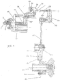
- the extraction device or unit of this invention is connected to a shaft of the forging machine (not shown) preferably to the main drive shaft indicated by 22; the hub of a cam-holder 21 is keyed on said shaft, and a first cam 20 is fastened, by means of screws or the like, to the flange of said cam-holder.
- a first lever 25 is hinged on a pin 26 integral with the casing of the forging machine; an end of lever 25 bears a roller 23 connected to the same through a pin 24.
- Cam 20 acts on roller 23, determining the oscillatory motion of lever 25 around the axis of pin 26.
- a first rod or tie-rod is hinged at the opposite end of lever 25, by known means, pins or the like.
- rod 27 is hinged to an end of lever 25 and, at the opposite end, to a second lever 28; the latter is pivoted on the casing of the forging machine though a pin 35. Therefore, the control of the oscillation of lever 28 around pin 35 is obtained by means of rod 27.
- a second rod or tie-rod 29 is connected, that is suitable to act on a third lever 30, keyed on a shaft 31 supported by the casing of the forging machine by means of bushings 32 or the like.
- Said lever 30 determines the oscillatory motion of shaft 31.
- a second cam 33 is keyed, which acts, by means of a small roller 34, on a fourth lever 10, substantially triangle-shaped.
- Said lever 10 is pivoted on the casing of the forging machine by means of a pin 36, around which it oscillates, controlled by cam 33.
- a spring 29' is fitted on the second rod 29 and exercises the action of elastic return for the whole control mechanism, i.e., levers 25, 28, 30, rods 27, 29 and cam 33.
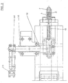
- the vertical branch indicated by 10' of lever 10 co-operates with a first peg 11, located in a seat 12 behind the forming punch, indicated by 1; a spring 13 is fitted on peg 11, which slides with an alternating rectilinear motion in seat 12, pushed forwards by the vertical branch 10' of lever 10 and is returned by said spring.
- a flange To the casing of the forging machine there is fastened by a flange the forging equipment constituted by punch 1, of a known type, wherein a second peg 2 is located that is aligned with peg 11 and is also provided with a fitted on spring, indicated by 3. Said peg 2 moves axially in its own seat, pushed forwards by peg 11 located behind it and coaxial with respect to the same, and elastically returned by spring 3.
- the forging of the head of the small metal items starting from wire is realised with the shank retained in punch 1 and bucked in the axial direction by peg 2.
- peg 2 rests on a conventional ledge collar.
- the extraction of the shank after the forging of the head is caused by the same peg 2 pushed in the axial direction, in a direction opposite to the edge collar, by the activation device.
- Spring 3 brings then the peg in strike position on the collar.
- punch 1, peg 2 and spring 3 constitutes an independent tool, connected to the remaining part of the extraction unit by means of a flanged connection with lag screws.
- Expulsion activation is ensured by lever 10 which pushes, with its first vertical branch 10', peg 11, driven in element 12, in an axial direction against peg 2.
- the return of peg 11 is ensured by the coaxial spring 13.
- lever 10 The oscillatory movement of lever 10 is caused by the described kinematic chain of cams and levers which is driven by the main drive shaft 22 of the automatic machine.
- the kinematic chain of cams and levers starts from cam 2, flanged with screws to cam-holder 21, keyed on the main drive shaft 22.
- Cam 20 activates lever 25 by means of roller 23 mounted on lever 25 with pin 24.
- lever 25 oscillates around the axis of pin 26 and, in its turn, controls the first rod or tie-rod 27 by means of the end opposite to the one that bears roller 23.
- Tie-rod 27 controls therefore lever 28 which, by oscillating around axis 35, transmits an alternating motion to tie-rod 29 which, in its turn, determines the oscillatory motion of lever 30.
- Spring 29' coaxial with respect to tie-rod 29, ensures the return motion of the kinematic chain of cams and levers which, driven by the main drive shaft, activates lever 10.
- the device for the extraction of small metal items of the present invention does not involve the removal of part of the equipment even if the extraction of the items is not included in the process; the extraction unit is in fact located behind the forming tool and never ever interferes with the same.
Landscapes
- Engineering & Computer Science (AREA)
- Mechanical Engineering (AREA)
- Forging (AREA)
- Extraction Or Liquid Replacement (AREA)
- Electrical Discharge Machining, Electrochemical Machining, And Combined Machining (AREA)
- Sampling And Sample Adjustment (AREA)
Applications Claiming Priority (2)
| Application Number | Priority Date | Filing Date | Title |
|---|---|---|---|
| ITMI980825 | 1998-04-17 | ||
| IT1998MI000825A IT1303028B1 (it) | 1998-04-17 | 1998-04-17 | Dispositivo di estrazione di minuterie metalliche |
Publications (3)
| Publication Number | Publication Date |
|---|---|
| EP0950449A2 true EP0950449A2 (de) | 1999-10-20 |
| EP0950449A3 EP0950449A3 (de) | 2001-04-04 |
| EP0950449B1 EP0950449B1 (de) | 2003-12-17 |
Family
ID=11379827
Family Applications (1)
| Application Number | Title | Priority Date | Filing Date |
|---|---|---|---|
| EP98119927A Expired - Lifetime EP0950449B1 (de) | 1998-04-17 | 1998-10-21 | Vorrichtung zum Auswerfen von metallischen Werkstücken |
Country Status (6)
| Country | Link |
|---|---|
| US (1) | US6067837A (de) |
| EP (1) | EP0950449B1 (de) |
| AT (1) | ATE256513T1 (de) |
| DE (1) | DE69820590T2 (de) |
| ES (1) | ES2212820T3 (de) |
| IT (1) | IT1303028B1 (de) |
Cited By (1)
| Publication number | Priority date | Publication date | Assignee | Title |
|---|---|---|---|---|
| CN112025003A (zh) * | 2020-08-24 | 2020-12-04 | 胡梅生 | 一种工业用塑料短管攻丝专用设备 |
Families Citing this family (1)
| Publication number | Priority date | Publication date | Assignee | Title |
|---|---|---|---|---|
| CN112605327A (zh) * | 2020-12-29 | 2021-04-06 | 张媛淇 | 一种新能源汽车轮毂锻造装置 |
Family Cites Families (8)
| Publication number | Priority date | Publication date | Assignee | Title |
|---|---|---|---|---|
| US2547304A (en) * | 1949-03-19 | 1951-04-03 | Gkn Group Services Ltd | Ejector mechanism for heading and like machines |
| NL301772A (de) * | 1963-12-13 | |||
| DE2135405B2 (de) * | 1971-07-15 | 1974-08-08 | Gebr. Hilgeland, 5600 Wuppertal | Auswerferanordnung an einer Doppeldruckpresse, deren Stempelträger um eine am Pressenschlitten vorgesehene Achse schwenkbar und gegebenenfalls in den Endstellungen arretierbar ist |
| US3820376A (en) * | 1972-08-18 | 1974-06-28 | Peltzer & Ehlers | Variable stroke ejector mechanism |
| DE2812695C3 (de) * | 1978-03-23 | 1981-02-19 | Hatebur Umformmaschinen Ag, Basel (Schweiz) | Vorrichtung zum stempelseitigen Auswerfen eines Preßlings auf einer Querförderpresse zur spanlosen Metallumformung |
| US4488426A (en) * | 1980-08-14 | 1984-12-18 | The National Machinery Company | Forging machine for producing rivets or the like having running adjustments |
| US4538437A (en) * | 1984-06-25 | 1985-09-03 | The National Machinery Company | Forging machine kickout drive with running adjustment |
| DE4215451A1 (de) * | 1992-05-11 | 1993-11-18 | Schuler Gmbh L | Antrieb für einen patrizenseitigen Auswerfer in einer mechanischen Umformpresse |
-
1998
- 1998-04-17 IT IT1998MI000825A patent/IT1303028B1/it active IP Right Grant
- 1998-10-21 EP EP98119927A patent/EP0950449B1/de not_active Expired - Lifetime
- 1998-10-21 AT AT98119927T patent/ATE256513T1/de not_active IP Right Cessation
- 1998-10-21 ES ES98119927T patent/ES2212820T3/es not_active Expired - Lifetime
- 1998-10-21 DE DE1998620590 patent/DE69820590T2/de not_active Expired - Lifetime
- 1998-10-29 US US09/182,045 patent/US6067837A/en not_active Expired - Lifetime
Cited By (2)
| Publication number | Priority date | Publication date | Assignee | Title |
|---|---|---|---|---|
| CN112025003A (zh) * | 2020-08-24 | 2020-12-04 | 胡梅生 | 一种工业用塑料短管攻丝专用设备 |
| CN112025003B (zh) * | 2020-08-24 | 2022-06-24 | 北京中财万鑫科技有限公司 | 一种工业用塑料短管攻丝专用设备 |
Also Published As
| Publication number | Publication date |
|---|---|
| EP0950449A3 (de) | 2001-04-04 |
| ES2212820T3 (es) | 2004-08-01 |
| ATE256513T1 (de) | 2004-01-15 |
| DE69820590D1 (de) | 2004-01-29 |
| ITMI980825A1 (it) | 1999-10-17 |
| IT1303028B1 (it) | 2000-10-20 |
| EP0950449B1 (de) | 2003-12-17 |
| DE69820590T2 (de) | 2004-11-18 |
| US6067837A (en) | 2000-05-30 |
Similar Documents
| Publication | Publication Date | Title |
|---|---|---|
| US2106274A (en) | Apparatus for cutting bar stock | |
| US6067837A (en) | Device for the extraction of small metal items | |
| US2271257A (en) | Ejecting mechanism for headers | |
| US2069511A (en) | Upsetting mechanism | |
| US6751997B1 (en) | Stamping press arrangement and method | |
| US3720968A (en) | Machine for the production of half-punched rivets | |
| US4136417A (en) | Method and machine for forming a hollow rivet | |
| KR920009831B1 (ko) | 클램핑 및 해머링 장치 | |
| US2721343A (en) | Blank handling apparatus for headers | |
| US3381513A (en) | Rod heading and trimming method and machine | |
| US27238A (en) | Kivet awd bolt machine | |
| EP0950447A2 (de) | Einstellvorrichtung für eine Schmiedepresse | |
| US3273434A (en) | Shearing machine and method | |
| US45116A (en) | Improved machine for making rivets | |
| US9508A (en) | Method of heading screw-blanks | |
| US569406A (en) | campbell | |
| JPH03274Y2 (de) | ||
| EP0950448B1 (de) | Werkzeughalter für eine Presse | |
| US3046653A (en) | Forging of rings and similar parts | |
| US13118A (en) | Burgh | |
| US459155A (en) | Bolt oe rivet machine | |
| JP3125009U (ja) | 圧造成形機 | |
| KR900000241Y1 (ko) | 프레스기의 세이빙 복합 금형 | |
| US1179481A (en) | Nut-making machine. | |
| US385128A (en) | Nut-machine |
Legal Events
| Date | Code | Title | Description |
|---|---|---|---|
| PUAI | Public reference made under article 153(3) epc to a published international application that has entered the european phase |
Free format text: ORIGINAL CODE: 0009012 |
|
| AK | Designated contracting states |
Kind code of ref document: A2 Designated state(s): AT BE CH CY DE DK ES FI FR GB GR IE LI LU MC NL PT SE |
|
| AX | Request for extension of the european patent |
Free format text: AL;LT;LV;MK;RO;SI |
|
| PUAL | Search report despatched |
Free format text: ORIGINAL CODE: 0009013 |
|
| AK | Designated contracting states |
Kind code of ref document: A3 Designated state(s): AT BE CH CY DE DK ES FI FR GB GR IE IT LI LU MC NL PT SE |
|
| AX | Request for extension of the european patent |
Free format text: AL;LT;LV;MK;RO;SI |
|
| 17P | Request for examination filed |
Effective date: 20010709 |
|
| AKX | Designation fees paid |
Free format text: AT BE CH CY DE DK ES FI FR GB GR IE LI LU MC NL PT SE |
|
| 17Q | First examination report despatched |
Effective date: 20021014 |
|
| GRAH | Despatch of communication of intention to grant a patent |
Free format text: ORIGINAL CODE: EPIDOS IGRA |
|
| GRAS | Grant fee paid |
Free format text: ORIGINAL CODE: EPIDOSNIGR3 |
|
| GRAA | (expected) grant |
Free format text: ORIGINAL CODE: 0009210 |
|
| AK | Designated contracting states |
Kind code of ref document: B1 Designated state(s): AT BE CH CY DE DK ES FI FR GB GR IE LI LU MC NL PT SE |
|
| PG25 | Lapsed in a contracting state [announced via postgrant information from national office to epo] |
Ref country code: NL Free format text: LAPSE BECAUSE OF FAILURE TO SUBMIT A TRANSLATION OF THE DESCRIPTION OR TO PAY THE FEE WITHIN THE PRESCRIBED TIME-LIMIT Effective date: 20031217 Ref country code: LI Free format text: LAPSE BECAUSE OF FAILURE TO SUBMIT A TRANSLATION OF THE DESCRIPTION OR TO PAY THE FEE WITHIN THE PRESCRIBED TIME-LIMIT Effective date: 20031217 Ref country code: FR Free format text: LAPSE BECAUSE OF FAILURE TO SUBMIT A TRANSLATION OF THE DESCRIPTION OR TO PAY THE FEE WITHIN THE PRESCRIBED TIME-LIMIT Effective date: 20031217 Ref country code: FI Free format text: LAPSE BECAUSE OF FAILURE TO SUBMIT A TRANSLATION OF THE DESCRIPTION OR TO PAY THE FEE WITHIN THE PRESCRIBED TIME-LIMIT Effective date: 20031217 Ref country code: CY Free format text: LAPSE BECAUSE OF FAILURE TO SUBMIT A TRANSLATION OF THE DESCRIPTION OR TO PAY THE FEE WITHIN THE PRESCRIBED TIME-LIMIT Effective date: 20031217 Ref country code: CH Free format text: LAPSE BECAUSE OF FAILURE TO SUBMIT A TRANSLATION OF THE DESCRIPTION OR TO PAY THE FEE WITHIN THE PRESCRIBED TIME-LIMIT Effective date: 20031217 Ref country code: BE Free format text: LAPSE BECAUSE OF FAILURE TO SUBMIT A TRANSLATION OF THE DESCRIPTION OR TO PAY THE FEE WITHIN THE PRESCRIBED TIME-LIMIT Effective date: 20031217 Ref country code: AT Free format text: LAPSE BECAUSE OF FAILURE TO SUBMIT A TRANSLATION OF THE DESCRIPTION OR TO PAY THE FEE WITHIN THE PRESCRIBED TIME-LIMIT Effective date: 20031217 |
|
| REG | Reference to a national code |
Ref country code: GB Ref legal event code: FG4D |
|
| REG | Reference to a national code |
Ref country code: CH Ref legal event code: EP |
|
| REG | Reference to a national code |
Ref country code: IE Ref legal event code: FG4D |
|
| REF | Corresponds to: |
Ref document number: 69820590 Country of ref document: DE Date of ref document: 20040129 Kind code of ref document: P |
|
| PG25 | Lapsed in a contracting state [announced via postgrant information from national office to epo] |
Ref country code: SE Free format text: LAPSE BECAUSE OF FAILURE TO SUBMIT A TRANSLATION OF THE DESCRIPTION OR TO PAY THE FEE WITHIN THE PRESCRIBED TIME-LIMIT Effective date: 20040317 Ref country code: GR Free format text: LAPSE BECAUSE OF FAILURE TO SUBMIT A TRANSLATION OF THE DESCRIPTION OR TO PAY THE FEE WITHIN THE PRESCRIBED TIME-LIMIT Effective date: 20040317 Ref country code: DK Free format text: LAPSE BECAUSE OF FAILURE TO SUBMIT A TRANSLATION OF THE DESCRIPTION OR TO PAY THE FEE WITHIN THE PRESCRIBED TIME-LIMIT Effective date: 20040317 |
|
| NLV1 | Nl: lapsed or annulled due to failure to fulfill the requirements of art. 29p and 29m of the patents act | ||
| REG | Reference to a national code |
Ref country code: CH Ref legal event code: PL |
|
| REG | Reference to a national code |
Ref country code: ES Ref legal event code: FG2A Ref document number: 2212820 Country of ref document: ES Kind code of ref document: T3 |
|
| PG25 | Lapsed in a contracting state [announced via postgrant information from national office to epo] |
Ref country code: LU Free format text: LAPSE BECAUSE OF NON-PAYMENT OF DUE FEES Effective date: 20041021 Ref country code: IE Free format text: LAPSE BECAUSE OF NON-PAYMENT OF DUE FEES Effective date: 20041021 Ref country code: GB Free format text: LAPSE BECAUSE OF NON-PAYMENT OF DUE FEES Effective date: 20041021 |
|
| PLBE | No opposition filed within time limit |
Free format text: ORIGINAL CODE: 0009261 |
|
| STAA | Information on the status of an ep patent application or granted ep patent |
Free format text: STATUS: NO OPPOSITION FILED WITHIN TIME LIMIT |
|
| PG25 | Lapsed in a contracting state [announced via postgrant information from national office to epo] |
Ref country code: MC Free format text: LAPSE BECAUSE OF NON-PAYMENT OF DUE FEES Effective date: 20041031 |
|
| 26N | No opposition filed |
Effective date: 20040920 |
|
| EN | Fr: translation not filed | ||
| GBPC | Gb: european patent ceased through non-payment of renewal fee |
Effective date: 20041021 |
|
| REG | Reference to a national code |
Ref country code: IE Ref legal event code: MM4A |
|
| PG25 | Lapsed in a contracting state [announced via postgrant information from national office to epo] |
Ref country code: PT Free format text: LAPSE BECAUSE OF NON-PAYMENT OF DUE FEES Effective date: 20040517 |
|
| PGFP | Annual fee paid to national office [announced via postgrant information from national office to epo] |
Ref country code: DE Payment date: 20171129 Year of fee payment: 20 |
|
| PGFP | Annual fee paid to national office [announced via postgrant information from national office to epo] |
Ref country code: ES Payment date: 20171109 Year of fee payment: 20 |
|
| REG | Reference to a national code |
Ref country code: DE Ref legal event code: R071 Ref document number: 69820590 Country of ref document: DE |
|
| REG | Reference to a national code |
Ref country code: ES Ref legal event code: FD2A Effective date: 20200804 |
|
| PG25 | Lapsed in a contracting state [announced via postgrant information from national office to epo] |
Ref country code: ES Free format text: LAPSE BECAUSE OF EXPIRATION OF PROTECTION Effective date: 20181022 |