EP0950139B1 - Tooth arrangement - Google Patents
Tooth arrangement Download PDFInfo
- Publication number
- EP0950139B1 EP0950139B1 EP96943414A EP96943414A EP0950139B1 EP 0950139 B1 EP0950139 B1 EP 0950139B1 EP 96943414 A EP96943414 A EP 96943414A EP 96943414 A EP96943414 A EP 96943414A EP 0950139 B1 EP0950139 B1 EP 0950139B1
- Authority
- EP
- European Patent Office
- Prior art keywords
- aperture
- parts
- male
- female
- locking body
- Prior art date
- Legal status (The legal status is an assumption and is not a legal conclusion. Google has not performed a legal analysis and makes no representation as to the accuracy of the status listed.)
- Expired - Lifetime
Links
- 125000006850 spacer group Chemical group 0.000 claims abstract description 13
- 239000012858 resilient material Substances 0.000 claims description 5
- 239000004636 vulcanized rubber Substances 0.000 claims description 3
- 230000006835 compression Effects 0.000 claims description 2
- 238000007906 compression Methods 0.000 claims description 2
- 208000004188 Tooth Wear Diseases 0.000 claims 1
- 238000000926 separation method Methods 0.000 claims 1
- 101100289792 Squirrel monkey polyomavirus large T gene Proteins 0.000 description 1
- 238000003780 insertion Methods 0.000 description 1
- 230000037431 insertion Effects 0.000 description 1
- 239000002184 metal Substances 0.000 description 1
- 239000007787 solid Substances 0.000 description 1
- 238000003466 welding Methods 0.000 description 1
Images


Classifications
-
- E—FIXED CONSTRUCTIONS
- E02—HYDRAULIC ENGINEERING; FOUNDATIONS; SOIL SHIFTING
- E02F—DREDGING; SOIL-SHIFTING
- E02F9/00—Component parts of dredgers or soil-shifting machines, not restricted to one of the kinds covered by groups E02F3/00 - E02F7/00
- E02F9/28—Small metalwork for digging elements, e.g. teeth scraper bits
- E02F9/2808—Teeth
- E02F9/2816—Mountings therefor
- E02F9/2833—Retaining means, e.g. pins
- E02F9/2841—Retaining means, e.g. pins resilient
Definitions
- the present invention relates to a tooth arrangement used in excavators, for example, attached to the lower edge of the bucket.
- the tooth arrangement consists of two parts, one part being attached to the excavator bucket by welding or some other means, and constituting a male part.
- the other part of the tooth arrangement which is to constitute the part actually working the ground is the female part.
- the two parts are joined together and, when joined, produce a transverse aperture running through the arrangement.
- a locking body is then placed in said aperture. It has been found that when the exchangeable working part of the tooth arrangement becomes worn, it becomes unstable due to the properties of the transverse aperture and the locking body.
- a prior art tooth arrangement of the type here concerned is known from SE-A-429 051 , c f. also US-A-2 716 822 and DE-A-3 315 024 .
- the object of the present invention is to eliminate said instability and this is achieved by using an aperture composed of an intermediate part and two identical end parts of the same width, the intermediate part, however, having greater width.
- a locking body is developed for this aperture, said body comprising two elongate parts located parallel with each other and having flat surfaces opposite each other.
- the width of the locking body is adapted along its length to fit said aperture.
- the two flat surfaces are provided with one or more outwardly directed spacers restricting the approach of the two flat surfaces.
- the space between the two flat surfaces is filled with a resilient material such as vulcanized rubber. It has been found advantageous to provide each of the two parts of the locking body with a spacer at each end and a spacer between them. In this way the approach of the surfaces towards each other is restricted, thereby eliminating the drawback of an unstable working part of the tooth arrangement.
- the tip of the male part prefferably has a cross section in the shape of a T, for the tip to be as stable as possible and for the innermost end of the female part to be designed to fit the tip of the male part so that the two parts assume a position in relation to each other which is as immovable as possible. Instability of the exchangeable part in relation to the fixed part is thus also reduced.
- the drawings show a tooth arrangement 5 comprising a male part 2 intended to be welded to a cutter or the edge of an excavator bucket 6.
- Said male part is provided with a tip 26 for insertion into an aperture 24 in the female part 1.
- the female part 1 is a part for working the ground, which can be exchanged when it has become worn.
- the male and female parts form an aperture 3 situated on each side of the inserted tip 26. Between these two apertures 3 is an intermediate aperture.
- the two apertures 3 are identical and are arranged immediately opposite each other in two side walls of the female part. Between the two apertures the upper surface of the tip 26 of the male part 2 forms part of the intermediate aperture 25 and the remaining part of the intermediate aperture 25 is formed by the intermediate wall parts situated between the side walls of the female part 1.
- the two apertures 3 are narrower than the aperture 25.
- the apertures 3 are formed in the wall parts 22 and 23.
- a locking body 4 is placed in the aperture 3 and 25, this body comprising two metal parts 7 and 8, each having opposing flat surfaces.
- Each part 7 and 8 is provided with an intermediate part 9 and 10, respectively, and two end parts 11, 12 and 13, 14, respectively.
- the two flat surfaces are provided with spacers.
- the part 7 has spacers 16 and 17 at its ends 11 and 12 and a spacer 15 at its intermediate part 9.
- spacers 18 and 19 at its ends 13 and 14 and with a spacer 20 at its intermediate part 10.
- the space between the surfaces of the bar-like parts shown in Figure 10 is filled with a resilient material which may consist of vulcanized rubber.
- the locking body 4 shown in Figure 9 can thus be influenced in such a way that both flat surfaces of the parts 7 and 8 can move towards and away from each other. However, the parts 7 and 8 can never approach each other so far as to come into contact. The spacers ensure that, at maximum compression, the two flat surface will still be a certain distance from each other.
- the two parts 7 and 8 will be pressed together so that the locking body can be inserted through the aperture 3.
- the two parts 7 and 8 will move apart so that the intermediate part of the locking body adjusted to the aperture 25 and the ends to the apertures 3.
- the tip 26 of the male part has a cross section in the form of a T and that the cross section has been made as solid as possible. This can be achieved, for instance, by making the upright of the T as long as possible and as wide as possible and suiting the innermost end 24 of the aperture of the female part to the tip 26 of the male part so that the walls of the female part at the tip of the male part abut the tip of the male part as tightly as possible.
- the tip of the male part has a cross section in the form of a T and the innermost part of the aperture in the female part is shaped to fit this T-shaped cross section it is obvious that the transverse parts of the bar of the T will be clamped between two surfaces inside the innermost part of the female part and the actual tooth can be worn rather considerably from below without it falling off the male part.
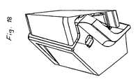
- Figures 14-18 show the actual core of the tooth arrangement, i.e. both attachment parts to a cutter and the tooth part itself have been removed.
- the actual core part can be used in any type of attachment part and together with any type of tooth part.
- the Figures thus show only the region of the tooth arrangement containing the tip of the male part and the aperture of the female part, and the transverse aperture with locking body.
- the male part 26 has a cross section in the form of a large T.
- the cross section thus has an upright and two outwardly directed cross bars which may be considered to form a yoke.
- the lower side of each cross bar is machined in such a way as to acquire the character of an inclined surface forming an angle with the centre line of the two bars in such a way that the surface has a shorter distance to said centre line at the upright and a longer distance at the outermost end of the bar.
- the interior of the female body is shaped correspondingly so that when male and female parts are joined these inclined surfaces will function as a locking device for the male and female body, thereby allowing increased wear on the actual tooth from below, without the male and female parts becoming separated from each other.
- These two inclined surfaces can of course be replaced with other types of surfaces filling the same function, i.e. preventing the male and female parts becoming separated from each other due to wear.
Landscapes
- Engineering & Computer Science (AREA)
- Mining & Mineral Resources (AREA)
- Civil Engineering (AREA)
- General Engineering & Computer Science (AREA)
- Structural Engineering (AREA)
- Component Parts Of Construction Machinery (AREA)
- Gears, Cams (AREA)
- Massaging Devices (AREA)
- Shovels (AREA)
- Crystals, And After-Treatments Of Crystals (AREA)
- Dental Tools And Instruments Or Auxiliary Dental Instruments (AREA)
Priority Applications (1)
| Application Number | Priority Date | Filing Date | Title |
|---|---|---|---|
| DK96943414.1T DK0950139T3 (da) | 1996-11-15 | 1996-11-15 | Tandindretning |
Applications Claiming Priority (1)
| Application Number | Priority Date | Filing Date | Title |
|---|---|---|---|
| PCT/SE1996/001481 WO1998022664A1 (en) | 1996-11-15 | 1996-11-15 | Tooth arrangement |
Publications (2)
| Publication Number | Publication Date |
|---|---|
| EP0950139A1 EP0950139A1 (en) | 1999-10-20 |
| EP0950139B1 true EP0950139B1 (en) | 2009-12-16 |
Family
ID=20402254
Family Applications (1)
| Application Number | Title | Priority Date | Filing Date |
|---|---|---|---|
| EP96943414A Expired - Lifetime EP0950139B1 (en) | 1996-11-15 | 1996-11-15 | Tooth arrangement |
Country Status (11)
| Country | Link |
|---|---|
| US (1) | US6385871B1 (es) |
| EP (1) | EP0950139B1 (es) |
| AT (1) | ATE452250T1 (es) |
| AU (1) | AU739857B2 (es) |
| CA (1) | CA2271753C (es) |
| DE (1) | DE69638100D1 (es) |
| DK (1) | DK0950139T3 (es) |
| ES (1) | ES2334180T3 (es) |
| HK (1) | HK1025611A1 (es) |
| PT (1) | PT950139E (es) |
| WO (1) | WO1998022664A1 (es) |
Families Citing this family (29)
| Publication number | Priority date | Publication date | Assignee | Title |
|---|---|---|---|---|
| AU7087698A (en) * | 1998-03-02 | 1999-09-20 | Componenta Wear Parts Aktiebolag | Tooth arrangement |
| ES2146186B1 (es) * | 1998-12-02 | 2001-04-01 | Metalogenia Sa | Perfeccionamientos en los elementos de anclaje y retencion destinados a maquinaria de obras publicas y similares. |
| ATE492692T1 (de) * | 2002-09-19 | 2011-01-15 | Esco Corp | VERSCHLEIßANORDNUNG UND VERRIEGELUNG FÜR EINE BAGGERSCHAUFEL. |
| FR2846017B1 (fr) * | 2002-10-17 | 2005-02-11 | Afe Metal | Dispositif de liaison d'accouplement entre des pieces d'usure aux extremites d'outils receptacles en usage sur les engins de travaux publics |
| US20060010725A1 (en) * | 2004-07-14 | 2006-01-19 | Jackson Michael J | Excavating tooth and adapter |
| ES2900345T3 (es) | 2006-03-30 | 2022-03-16 | Esco Group Llc | Conjunto de desgaste |
| US20080005940A1 (en) * | 2006-07-10 | 2008-01-10 | Esco Corporation | Assembly for securing a wear |
| WO2008025062A1 (en) * | 2006-08-28 | 2008-03-06 | Cutting Edges Replacement Parts Pty Ltd | Locking pin and a locking pin arrangement |
| US20080092412A1 (en) * | 2006-10-24 | 2008-04-24 | Esco Corporation | Wear Assembly For An Excavating Bucket |
| UA106391C2 (ru) * | 2009-10-30 | 2014-08-26 | Эско Корпорейшн | Сменный комплект для землеройного оборудования |
| EP2507438A1 (en) * | 2009-12-11 | 2012-10-10 | CQMS Pty Ltd | Mounting of wear members |
| WO2011088511A1 (en) * | 2010-01-20 | 2011-07-28 | Bradken Resources Pty Limited | Excavation tooth assembly |
| US9388553B2 (en) * | 2013-05-31 | 2016-07-12 | Caterpillar Inc. | Retainer systems for ground engaging tools |
| US9840829B2 (en) | 2015-12-01 | 2017-12-12 | Srj, Inc. | Flex pin |
| EP3483350A1 (en) * | 2016-07-06 | 2019-05-15 | Metalogenia Research & Technologies S.L. | Wear or protection system for a tool of a machine for moving earth and corresponding pin |
| US10400427B2 (en) | 2017-05-31 | 2019-09-03 | Srj, Inc. | Flex pin |
| USD842345S1 (en) | 2017-07-21 | 2019-03-05 | Caterpillar Inc. | Lip shroud for a ground engaging machine implement |
| USD832309S1 (en) | 2017-08-30 | 2018-10-30 | Caterpillar Inc. | Lip shroud for a ground engaging machine implement |
| USD842347S1 (en) | 2017-10-11 | 2019-03-05 | Caterpillar Inc. | Shroud for a ground engaging machine implement |
| USD842346S1 (en) | 2017-10-11 | 2019-03-05 | Caterpillar Inc. | Shroud for a ground engaging machine implement |
| USD882644S1 (en) | 2018-10-03 | 2020-04-28 | Caterpillar Inc. | Bucket shroud |
| USD882645S1 (en) | 2018-10-03 | 2020-04-28 | Caterpillar Inc. | Bucket shroud |
| USD873306S1 (en) | 2018-10-03 | 2020-01-21 | Caterpillar Inc. | Bucket shroud |
| USD882646S1 (en) | 2018-11-09 | 2020-04-28 | Caterpillar Inc. | Bucket shroud |
| USD927561S1 (en) | 2019-10-04 | 2021-08-10 | Caterpillar Inc. | Bucket shroud |
| USD928849S1 (en) * | 2019-10-04 | 2021-08-24 | Caterpillar Inc. | Bucket shroud |
| USD928848S1 (en) * | 2019-10-04 | 2021-08-24 | Caterpillar Inc. | Bucket shroud |
| USD959505S1 (en) | 2021-03-25 | 2022-08-02 | Caterpillar Inc. | Bucket shroud |
| USD978923S1 (en) | 2021-06-03 | 2023-02-21 | Caterpillar Inc. | Bucket shroud |
Family Cites Families (29)
| Publication number | Priority date | Publication date | Assignee | Title |
|---|---|---|---|---|
| US2716822A (en) * | 1946-08-21 | 1955-09-06 | Ernie L Launder | Digger tooth mounting |
| GB791022A (en) * | 1955-05-13 | 1958-02-19 | H And L Tooth Company | Improvements relating to retaining pins or pin fasteners |
| DE1074329B (de) * | 1955-05-13 | 1960-01-28 | H and L Tooth Company, Montebello, Calif. (V. St. A.) | Haltestift |
| US3020655A (en) * | 1958-12-08 | 1962-02-13 | Tooth H & L Co | Wear plate mounting for digger tooth construction |
| US3511126A (en) * | 1967-12-06 | 1970-05-12 | Caterpillar Tractor Co | Cylindrical retaining pin of substantially rigid construction |
| US3468210A (en) * | 1967-12-06 | 1969-09-23 | Caterpillar Tractor Co | Cylindrical retaining pin of rigid construction |
| US3879867A (en) * | 1968-12-04 | 1975-04-29 | Bofors Ab | Fastening means for retaining a digger tooth in a socket |
| SE333551B (es) * | 1968-12-04 | 1971-03-15 | Bofors Ab | |
| US3520224A (en) * | 1969-02-12 | 1970-07-14 | Hensley Equipment Co Inc | Retaining pin |
| US3608218A (en) * | 1969-03-24 | 1971-09-28 | Pengo Corp | Snap-type resilient retainer for excavating teeth |
| US3526049A (en) * | 1969-06-17 | 1970-09-01 | Irvin H Nichols | Retainer pin for earth engaging member |
| US3704753A (en) * | 1970-04-29 | 1972-12-05 | Hector Bernard Hasforth | Ripper shank |
| DE2547019B1 (de) * | 1975-10-21 | 1977-04-21 | O & K Orenstein & Koppel Ag, 1000 Berlin | Halterung zur loesbaren befestigung der zahnspitze eines baggerzahns |
| US4155665A (en) * | 1976-03-29 | 1979-05-22 | Caterpillar Tractor Co. | Resilient retention key for replaceable ripper teeth |
| CA1059556A (en) * | 1976-05-04 | 1979-07-31 | Esco Corporation | Locking device for earth moving tool |
| DE2713227C2 (de) * | 1977-03-25 | 1983-08-04 | O & K Orenstein & Koppel Ag, 1000 Berlin | Lösbare Befestigung eines rückwärts mit einer Hülse versehenen Baggerzahnes an einem in die Hülse eingreifenden Zahnhalter |
| US4087928A (en) * | 1977-04-07 | 1978-05-09 | International Harvester Company | Multi-sectional resilient retainer for excavating tooth |
| US4516340A (en) * | 1983-06-06 | 1985-05-14 | Launder Richard L | Attachment assembly for excavation teeth |
| US4579494A (en) * | 1983-11-23 | 1986-04-01 | Bierwith Robert S | Flexible locking pin |
| DE3731459C1 (de) * | 1987-09-18 | 1989-03-16 | Hoesch Ag | Schneidrad fuer Saug- oder Schaufelradbagger |
| US5469648A (en) * | 1993-02-02 | 1995-11-28 | Esco Corporation | Excavating tooth |
| US5394629A (en) * | 1993-06-21 | 1995-03-07 | Gh Hensley Industries, Inc. | Side-locking flex pin connector for excavation apparatus |
| SE504157C2 (sv) * | 1994-03-21 | 1996-11-25 | Componenta Wear Parts Ab | Tandarrangemang; sammanfogning med sprint |
| US5617655A (en) * | 1995-03-22 | 1997-04-08 | H&L Tooth Company | Securement pin for earth excavation teeth |
| US5561925A (en) * | 1995-07-25 | 1996-10-08 | Caterpillar Inc. | Tooth assembly and retaining mechanism |
| ES2138311T3 (es) * | 1996-07-01 | 2000-01-01 | Metalogenia Sa | Union de acoplamiento para dientes de maquinas excavadoras. |
| US5765301A (en) * | 1996-08-05 | 1998-06-16 | H&L Tooth Company | Retention apparatus for a ground engaging tool |
| US5852888A (en) * | 1996-11-08 | 1998-12-29 | Caterpillar Inc. | Apparatus for protecting a base of a bucket of an earth working machine |
| US6030143A (en) * | 1997-12-18 | 2000-02-29 | Esco Corporation | Locking pin for excavating equipment |
-
1996
- 1996-11-15 EP EP96943414A patent/EP0950139B1/en not_active Expired - Lifetime
- 1996-11-15 WO PCT/SE1996/001481 patent/WO1998022664A1/en active Application Filing
- 1996-11-15 DE DE69638100T patent/DE69638100D1/de not_active Expired - Lifetime
- 1996-11-15 DK DK96943414.1T patent/DK0950139T3/da active
- 1996-11-15 ES ES96943414T patent/ES2334180T3/es not_active Expired - Lifetime
- 1996-11-15 AT AT96943414T patent/ATE452250T1/de active
- 1996-11-15 US US09/284,996 patent/US6385871B1/en not_active Expired - Lifetime
- 1996-11-15 CA CA002271753A patent/CA2271753C/en not_active Expired - Lifetime
- 1996-11-15 PT PT96943414T patent/PT950139E/pt unknown
- 1996-11-15 AU AU12150/97A patent/AU739857B2/en not_active Expired
-
2000
- 2000-04-20 HK HK00102422.4A patent/HK1025611A1/xx not_active IP Right Cessation
Also Published As
| Publication number | Publication date |
|---|---|
| CA2271753A1 (en) | 1998-05-28 |
| DE69638100D1 (de) | 2010-01-28 |
| HK1025611A1 (en) | 2000-11-17 |
| DK0950139T3 (da) | 2010-04-06 |
| US6385871B1 (en) | 2002-05-14 |
| EP0950139A1 (en) | 1999-10-20 |
| ES2334180T3 (es) | 2010-03-05 |
| WO1998022664A1 (en) | 1998-05-28 |
| PT950139E (pt) | 2010-03-01 |
| ATE452250T1 (de) | 2010-01-15 |
| AU739857B2 (en) | 2001-10-25 |
| CA2271753C (en) | 2001-10-23 |
| AU1215097A (en) | 1998-06-10 |
Similar Documents
| Publication | Publication Date | Title |
|---|---|---|
| EP0950139B1 (en) | Tooth arrangement | |
| AU595931B2 (en) | Cable handling chain | |
| US6459037B2 (en) | Line guiding arrangement for supporting energy lines | |
| KR970001730B1 (ko) | 탄성로크를 구비한 굴착 투쓰 선단부 | |
| US4669507A (en) | Carrier for energy and supply lines | |
| EP0752031B1 (en) | Tooth arrangement | |
| JPS5821047B2 (ja) | ロツク装置 | |
| GB2145449A (en) | A multi-part cutting edge structure | |
| US4457380A (en) | Blades for earth moving machines | |
| DE2539118A1 (de) | Grabzahnanordnung fuer einen bagger | |
| EP4073894B1 (de) | Leitungsführungsvorrichtung für reinraumanwendungen sowie stützkette und kettenglied hierfür | |
| SU1017164A3 (ru) | Скребок скребкового конвейера дл подземных работ | |
| FR2435142A1 (fr) | Element de guidage et de marquage pour cables electriques | |
| DE1615689A1 (de) | Elektrische Steckverbindung mit isolierendem Gehaeuse | |
| US3864854A (en) | Digging tooth locking device | |
| EP0340571B1 (de) | Hilfsschalteraufsatzblock | |
| DE2726235C3 (de) | Verbindungselement für Hobel- oder Förderketten | |
| EP0197038B1 (en) | Corner tooth for a bucket | |
| US1107253A (en) | Dipper-tooth. | |
| MXPA99004507A (es) | Disposicion de diente | |
| DE2601797A1 (de) | Anordnung von zahn und zahnhalter eines greifers oder loeffels von erdbewegungsmaschinen | |
| AU727916B2 (en) | An assembly for connecting a shackle and pin together | |
| AU639806B2 (en) | Improved pin | |
| DE910181C (de) | Aufsteckbare Reihenklemme fuer elektrische Leitungen | |
| GB1580892A (en) | Chain support for cables |
Legal Events
| Date | Code | Title | Description |
|---|---|---|---|
| PUAI | Public reference made under article 153(3) epc to a published international application that has entered the european phase |
Free format text: ORIGINAL CODE: 0009012 |
|
| 17P | Request for examination filed |
Effective date: 19990611 |
|
| AK | Designated contracting states |
Kind code of ref document: A1 Designated state(s): AT BE CH DE DK ES FI FR GB GR IE IT LI LU MC NL PT SE |
|
| AX | Request for extension of the european patent |
Free format text: AL PAYMENT 19990611;LT PAYMENT 19990611;LV PAYMENT 19990611;RO PAYMENT 19990611;SI PAYMENT 19990611 |
|
| 17Q | First examination report despatched |
Effective date: 20010215 |
|
| APBT | Appeal procedure closed |
Free format text: ORIGINAL CODE: EPIDOSNNOA9E |
|
| RAP1 | Party data changed (applicant data changed or rights of an application transferred) |
Owner name: COMBI WEAR PARTS AB |
|
| APAF | Appeal reference modified |
Free format text: ORIGINAL CODE: EPIDOSCREFNE |
|
| GRAP | Despatch of communication of intention to grant a patent |
Free format text: ORIGINAL CODE: EPIDOSNIGR1 |
|
| GRAS | Grant fee paid |
Free format text: ORIGINAL CODE: EPIDOSNIGR3 |
|
| GRAA | (expected) grant |
Free format text: ORIGINAL CODE: 0009210 |
|
| AK | Designated contracting states |
Kind code of ref document: B1 Designated state(s): AT BE CH DE DK ES FI FR GB GR IE IT LI LU MC NL PT SE |
|
| AX | Request for extension of the european patent |
Extension state: AL LT LV RO SI |
|
| REG | Reference to a national code |
Ref country code: GB Ref legal event code: FG4D |
|
| REG | Reference to a national code |
Ref country code: CH Ref legal event code: NV Representative=s name: E. BLUM & CO. AG PATENT- UND MARKENANWAELTE VSP Ref country code: CH Ref legal event code: EP |
|
| REG | Reference to a national code |
Ref country code: IE Ref legal event code: FG4D |
|
| REF | Corresponds to: |
Ref document number: 69638100 Country of ref document: DE Date of ref document: 20100128 Kind code of ref document: P |
|
| REG | Reference to a national code |
Ref country code: PT Ref legal event code: SC4A Free format text: AVAILABILITY OF NATIONAL TRANSLATION Effective date: 20100222 |
|
| REG | Reference to a national code |
Ref country code: ES Ref legal event code: FG2A Ref document number: 2334180 Country of ref document: ES Kind code of ref document: T3 |
|
| REG | Reference to a national code |
Ref country code: GR Ref legal event code: EP Ref document number: 20100400309 Country of ref document: GR |
|
| REG | Reference to a national code |
Ref country code: NL Ref legal event code: T3 |
|
| REG | Reference to a national code |
Ref country code: SE Ref legal event code: TRGR Ref country code: DK Ref legal event code: T3 |
|
| LTIE | Lt: invalidation of european patent or patent extension |
Effective date: 20091216 |
|
| PLBE | No opposition filed within time limit |
Free format text: ORIGINAL CODE: 0009261 |
|
| STAA | Information on the status of an ep patent application or granted ep patent |
Free format text: STATUS: NO OPPOSITION FILED WITHIN TIME LIMIT |
|
| 26N | No opposition filed |
Effective date: 20100917 |
|
| PG25 | Lapsed in a contracting state [announced via postgrant information from national office to epo] |
Ref country code: MC Free format text: LAPSE BECAUSE OF NON-PAYMENT OF DUE FEES Effective date: 20101130 |
|
| REG | Reference to a national code |
Ref country code: HK Ref legal event code: GR Ref document number: 1025611 Country of ref document: HK |
|
| PG25 | Lapsed in a contracting state [announced via postgrant information from national office to epo] |
Ref country code: LU Free format text: LAPSE BECAUSE OF NON-PAYMENT OF DUE FEES Effective date: 20101115 |
|
| PGFP | Annual fee paid to national office [announced via postgrant information from national office to epo] |
Ref country code: PT Payment date: 20130515 Year of fee payment: 18 |
|
| PGFP | Annual fee paid to national office [announced via postgrant information from national office to epo] |
Ref country code: GR Payment date: 20131129 Year of fee payment: 18 |
|
| REG | Reference to a national code |
Ref country code: PT Ref legal event code: MM4A Free format text: LAPSE DUE TO NON-PAYMENT OF FEES Effective date: 20150515 |
|
| REG | Reference to a national code |
Ref country code: GR Ref legal event code: ML Ref document number: 20100400309 Country of ref document: GR Effective date: 20150604 |
|
| PG25 | Lapsed in a contracting state [announced via postgrant information from national office to epo] |
Ref country code: PT Free format text: LAPSE BECAUSE OF NON-PAYMENT OF DUE FEES Effective date: 20150515 |
|
| PG25 | Lapsed in a contracting state [announced via postgrant information from national office to epo] |
Ref country code: GR Free format text: LAPSE BECAUSE OF NON-PAYMENT OF DUE FEES Effective date: 20150604 |
|
| REG | Reference to a national code |
Ref country code: FR Ref legal event code: PLFP Year of fee payment: 20 |
|
| PGFP | Annual fee paid to national office [announced via postgrant information from national office to epo] |
Ref country code: IE Payment date: 20151130 Year of fee payment: 20 Ref country code: FI Payment date: 20151127 Year of fee payment: 20 Ref country code: DK Payment date: 20151125 Year of fee payment: 20 Ref country code: DE Payment date: 20151127 Year of fee payment: 20 Ref country code: IT Payment date: 20151124 Year of fee payment: 20 Ref country code: CH Payment date: 20151127 Year of fee payment: 20 Ref country code: GB Payment date: 20151127 Year of fee payment: 20 |
|
| PGFP | Annual fee paid to national office [announced via postgrant information from national office to epo] |
Ref country code: AT Payment date: 20151021 Year of fee payment: 20 Ref country code: SE Payment date: 20151127 Year of fee payment: 20 Ref country code: ES Payment date: 20151126 Year of fee payment: 20 Ref country code: FR Payment date: 20151117 Year of fee payment: 20 Ref country code: NL Payment date: 20151126 Year of fee payment: 20 Ref country code: BE Payment date: 20151130 Year of fee payment: 20 |
|
| REG | Reference to a national code |
Ref country code: DE Ref legal event code: R071 Ref document number: 69638100 Country of ref document: DE |
|
| REG | Reference to a national code |
Ref country code: NL Ref legal event code: MK Effective date: 20161114 |
|
| REG | Reference to a national code |
Ref country code: DK Ref legal event code: EUP Effective date: 20161115 |
|
| REG | Reference to a national code |
Ref country code: CH Ref legal event code: PL |
|
| REG | Reference to a national code |
Ref country code: GB Ref legal event code: PE20 Expiry date: 20161114 |
|
| REG | Reference to a national code |
Ref country code: IE Ref legal event code: MK9A |
|
| REG | Reference to a national code |
Ref country code: AT Ref legal event code: MK07 Ref document number: 452250 Country of ref document: AT Kind code of ref document: T Effective date: 20161115 |
|
| PG25 | Lapsed in a contracting state [announced via postgrant information from national office to epo] |
Ref country code: GB Free format text: LAPSE BECAUSE OF EXPIRATION OF PROTECTION Effective date: 20161114 Ref country code: IE Free format text: LAPSE BECAUSE OF EXPIRATION OF PROTECTION Effective date: 20161115 |
|
| REG | Reference to a national code |
Ref country code: ES Ref legal event code: FD2A Effective date: 20170224 |
|
| PG25 | Lapsed in a contracting state [announced via postgrant information from national office to epo] |
Ref country code: ES Free format text: LAPSE BECAUSE OF EXPIRATION OF PROTECTION Effective date: 20161116 |