EP0949415A2 - A fuel injection device for internal combustion engines - Google Patents
A fuel injection device for internal combustion engines Download PDFInfo
- Publication number
- EP0949415A2 EP0949415A2 EP98123745A EP98123745A EP0949415A2 EP 0949415 A2 EP0949415 A2 EP 0949415A2 EP 98123745 A EP98123745 A EP 98123745A EP 98123745 A EP98123745 A EP 98123745A EP 0949415 A2 EP0949415 A2 EP 0949415A2
- Authority
- EP
- European Patent Office
- Prior art keywords
- valve
- valve member
- fuel injection
- control
- injection device
- Prior art date
- Legal status (The legal status is an assumption and is not a legal conclusion. Google has not performed a legal analysis and makes no representation as to the accuracy of the status listed.)
- Granted
Links
- 238000002347 injection Methods 0.000 title claims abstract description 119
- 239000007924 injection Substances 0.000 title claims abstract description 119
- 239000000446 fuel Substances 0.000 title claims abstract description 74
- 238000002485 combustion reaction Methods 0.000 title claims description 5
- 238000007789 sealing Methods 0.000 claims description 51
- 230000033001 locomotion Effects 0.000 claims description 11
- 230000002093 peripheral effect Effects 0.000 claims description 8
- 230000006835 compression Effects 0.000 claims description 7
- 238000007906 compression Methods 0.000 claims description 7
- 230000007704 transition Effects 0.000 claims description 6
- 230000015572 biosynthetic process Effects 0.000 claims description 4
- 238000004891 communication Methods 0.000 claims description 2
- 238000007599 discharging Methods 0.000 claims 1
- 238000011144 upstream manufacturing Methods 0.000 claims 1
- 230000008901 benefit Effects 0.000 description 7
- 238000010586 diagram Methods 0.000 description 7
- 238000013461 design Methods 0.000 description 6
- 230000000694 effects Effects 0.000 description 3
- 230000005284 excitation Effects 0.000 description 3
- 230000004048 modification Effects 0.000 description 3
- 238000012986 modification Methods 0.000 description 3
- 238000011161 development Methods 0.000 description 2
- 238000009434 installation Methods 0.000 description 2
- 238000000034 method Methods 0.000 description 2
- 230000008569 process Effects 0.000 description 2
- 230000009467 reduction Effects 0.000 description 2
- 230000001960 triggered effect Effects 0.000 description 2
- 230000009471 action Effects 0.000 description 1
- 239000002828 fuel tank Substances 0.000 description 1
- 230000009347 mechanical transmission Effects 0.000 description 1
- 125000006850 spacer group Chemical group 0.000 description 1
- 230000007306 turnover Effects 0.000 description 1
Images


Classifications
-
- F—MECHANICAL ENGINEERING; LIGHTING; HEATING; WEAPONS; BLASTING
- F02—COMBUSTION ENGINES; HOT-GAS OR COMBUSTION-PRODUCT ENGINE PLANTS
- F02M—SUPPLYING COMBUSTION ENGINES IN GENERAL WITH COMBUSTIBLE MIXTURES OR CONSTITUENTS THEREOF
- F02M63/00—Other fuel-injection apparatus having pertinent characteristics not provided for in groups F02M39/00 - F02M57/00 or F02M67/00; Details, component parts, or accessories of fuel-injection apparatus, not provided for in, or of interest apart from, the apparatus of groups F02M39/00 - F02M61/00 or F02M67/00; Combination of fuel pump with other devices, e.g. lubricating oil pump
- F02M63/0012—Valves
- F02M63/0031—Valves characterized by the type of valves, e.g. special valve member details, valve seat details, valve housing details
- F02M63/0056—Throttling valves, e.g. having variable opening positions throttling the flow
-
- F—MECHANICAL ENGINEERING; LIGHTING; HEATING; WEAPONS; BLASTING
- F02—COMBUSTION ENGINES; HOT-GAS OR COMBUSTION-PRODUCT ENGINE PLANTS
- F02M—SUPPLYING COMBUSTION ENGINES IN GENERAL WITH COMBUSTIBLE MIXTURES OR CONSTITUENTS THEREOF
- F02M45/00—Fuel-injection apparatus characterised by having a cyclic delivery of specific time/pressure or time/quantity relationship
- F02M45/02—Fuel-injection apparatus characterised by having a cyclic delivery of specific time/pressure or time/quantity relationship with each cyclic delivery being separated into two or more parts
- F02M45/04—Fuel-injection apparatus characterised by having a cyclic delivery of specific time/pressure or time/quantity relationship with each cyclic delivery being separated into two or more parts with a small initial part, e.g. initial part for partial load and initial and main part for full load
- F02M45/08—Injectors peculiar thereto
-
- F—MECHANICAL ENGINEERING; LIGHTING; HEATING; WEAPONS; BLASTING
- F02—COMBUSTION ENGINES; HOT-GAS OR COMBUSTION-PRODUCT ENGINE PLANTS
- F02M—SUPPLYING COMBUSTION ENGINES IN GENERAL WITH COMBUSTIBLE MIXTURES OR CONSTITUENTS THEREOF
- F02M47/00—Fuel-injection apparatus operated cyclically with fuel-injection valves actuated by fluid pressure
- F02M47/02—Fuel-injection apparatus operated cyclically with fuel-injection valves actuated by fluid pressure of accumulator-injector type, i.e. having fuel pressure of accumulator tending to open, and fuel pressure in other chamber tending to close, injection valves and having means for periodically releasing that closing pressure
- F02M47/027—Electrically actuated valves draining the chamber to release the closing pressure
-
- F—MECHANICAL ENGINEERING; LIGHTING; HEATING; WEAPONS; BLASTING
- F02—COMBUSTION ENGINES; HOT-GAS OR COMBUSTION-PRODUCT ENGINE PLANTS
- F02M—SUPPLYING COMBUSTION ENGINES IN GENERAL WITH COMBUSTIBLE MIXTURES OR CONSTITUENTS THEREOF
- F02M63/00—Other fuel-injection apparatus having pertinent characteristics not provided for in groups F02M39/00 - F02M57/00 or F02M67/00; Details, component parts, or accessories of fuel-injection apparatus, not provided for in, or of interest apart from, the apparatus of groups F02M39/00 - F02M61/00 or F02M67/00; Combination of fuel pump with other devices, e.g. lubricating oil pump
- F02M63/0012—Valves
- F02M63/0014—Valves characterised by the valve actuating means
- F02M63/0015—Valves characterised by the valve actuating means electrical, e.g. using solenoid
- F02M63/0026—Valves characterised by the valve actuating means electrical, e.g. using solenoid using piezoelectric or magnetostrictive actuators
-
- F—MECHANICAL ENGINEERING; LIGHTING; HEATING; WEAPONS; BLASTING
- F02—COMBUSTION ENGINES; HOT-GAS OR COMBUSTION-PRODUCT ENGINE PLANTS
- F02M—SUPPLYING COMBUSTION ENGINES IN GENERAL WITH COMBUSTIBLE MIXTURES OR CONSTITUENTS THEREOF
- F02M63/00—Other fuel-injection apparatus having pertinent characteristics not provided for in groups F02M39/00 - F02M57/00 or F02M67/00; Details, component parts, or accessories of fuel-injection apparatus, not provided for in, or of interest apart from, the apparatus of groups F02M39/00 - F02M61/00 or F02M67/00; Combination of fuel pump with other devices, e.g. lubricating oil pump
- F02M63/0012—Valves
- F02M63/007—Details not provided for in, or of interest apart from, the apparatus of the groups F02M63/0014 - F02M63/0059
- F02M63/0078—Valve member details, e.g. special shape, hollow or fuel passages in the valve member
Landscapes
- Engineering & Computer Science (AREA)
- Chemical & Material Sciences (AREA)
- Combustion & Propulsion (AREA)
- Mechanical Engineering (AREA)
- General Engineering & Computer Science (AREA)
- Physics & Mathematics (AREA)
- Fluid Mechanics (AREA)
- Fuel-Injection Apparatus (AREA)
Abstract
Description
Die Erfindung geht von einer Kraftstoffeinspritzvorrichtung
für Brennkraftmaschinen nach der Gattung des Patentanspruchs
1 aus. Bei einer solchen, durch die DE 196 24 001 A1
bekannten Kraftstoffeinspritzeinrichtung ist der Ventilraum
in einer ersten Ausführung ohne Querschnittsverminderung mit
dem Steuerraum verbunden. Das Steuerventil steuert dabei bei
Betätigung durch den Piezoaktor den Abflußerschnitt zum
Abflußkanal hin entweder ganz auf oder schließt diesen. In
einer weiteren Ausführung ist der Ventilraum über ein
Verbindungskanal mit dem Steuerraum verbunden, wobei dieser
Verbindungskanal koaxial zum Ventilsitz zur Seite des
Abflußkanals liegt. Durch Betätigung des Steuerventilglieds
durch den Piezoaktor wird dabei entweder der
Abflußquerschnitt vom Ventilraum zum Abflußkanal hin ganz
geöffnet oder geschlossen oder es wird zur Erzielung einer
Voreinspritzung das Steuerventilglied vom Ventilsitz zum
Abflußkanal hin weg zum Eintritt des Verbindungskanals in
den Ventilraum bewegt, wobei in der Folge dieser Bewegung
der Steuerraum kurzzeitig über den Ventilraum zum
Abflußkanal hin geöffnet ist. Für eine anschließende
Haupteinspritzung wird das Steuerventilglied in eine
Mittelstellung bewegt, in der sowohl der Querschnitt zum
Abflußkanal hin als auch der Querschnitt des
Verbindungskanals in den Ventilraum hinein ganz geöffnet
sind. Diese Ausgestaltung hat den Nachteil, daß zur
Entlastung des Druckes im Steuerraum nur ein einziger
geometrisch festgelegter Abflußquerschnitt zum Abflußkanal
hin besteht. Die Menge der Voreinspritzung ist dabei in der
zweiten geschilderten Ausführung so, daß die
Verstellgeschwindigkeit des Steuerventilgliedes durch den
Piezoaktor und der geometrisch festgelegte Weg des
Steuerventilglieds bestimmende Größen für den Grad der
Entlastung des Druckes im Steuerraum sind. Insbesondere ist
der maximale Entlastungsquerschnitt sowohl für die
Entlastung für die Voreinspritzung als auch für die
Entlastung für die Haupteinspritzung gleich groß, was für
eine Feinabstimmung der Öffnungsgeschwindigkeit des
Einspritzventils bei verschiedenen Betriebszuständen von
Nachteil ist.The invention relates to a fuel injection device
for internal combustion engines according to the preamble of the
Die erfindungsgemäße Kraftstoffeinspritzvorrichtung mit den
kennzeichnenden Merkmalen des Patentanspruchs 1 hat dagegen
den Vorteil, daß durch das erfindungsgemäße Steuerventil
sequentiell zwei Abflußquerschnitte nacheinander
aufsteuerbar sind. Somit kann eine Gradation des
Abflußquerschnittes in Abhängigkeit vom Hub erzielt werden.
Insbesondere für geringe Entlastungen des Steuerdrucks im
Steuerraum kann dabei ein erster kleinerer Abflußquerschnitt
zur Wirkung kommen, mit dem mit höherer Genauigkeit die
Voreinspritzung eingestellt werden kann. Für die
Haupteinspritzung steht danach ein großer Abflußquerschnitt
zur Verfügung, der eine schnelle Bewegung des
Einspritzventilgliedes erlaubt. In vorteilhafter Weise ist
dabei gemäß Patentanspruch 2 ein hülsenförmiges
Schleppventilglied vorgesehen, das einen zweiten
Abflußquerschnitt des Abflußkanals steuert, wenn das
Steuerventilglied einen ersten, den Steuerraum entlastenden
Hub durchgeführt hat. Die dabei vor der Öffnung des zweiten
Abflußquerschnittes durch das Schleppventilglied erfolgende
Druckabsenkung im Ventilraum beziehungsweise Steuerraum
erleichtert ein schnelles Öffnen des zweiten
Abflußquerschnitts in der Nachfolge auf die Öffnung des
ersten Abflußquerschnitts bei der ersten Bewegung des
Schleppventilglieds. Damit kann insbesondere ein schnelles
Öffnen des Einspritzventilgliedes zum Beginn der
Haupteinspritzung erzielt werden.The fuel injection device according to the invention with the
characteristic features of
In der weiteren Ausgestaltung gemäß den Patentansprüche 3
bis 5 werden vorteilhafte Arten der Abflußquerschnittsbildung
vorgeschlagen. Zur Öffnung des zweiten
Abschlußquerschnitts durch das Schleppventilglied kann
dieses vorteilhaft gemäß Patentanspruch 6 durch einen
Mitnehmer am Steuerventilglied von seinem Hauptventilsitz
abgehoben werden. In alternativer Ausgestaltung gemäß
Patentanspruch 8 kann das Schleppventilglied vorteilhaft
auch durch eine Druckfeder bei entsprechender Absenkung des
Druckes im Ventilraum in Öffnungsstellung bewegt werden,
indem es nach Absenkung des Druckes dem Steuerventilglied
folgen kann. Dabei ist in einer Endstellung des
Steuerventilglieds der Abflußquerschnitt durch den
Querschnitt am Hauptventilsitz bestimmt. Die Ausgestaltung
gemäß Patentanspruch 9 bietet eine genaue Führung des
Schleppventilglieds auf dem Ventilstößel. Weiterhin kann die
Führungsqualität des Ventilstößels dadurch vergrößert
werden, daß gemäß Patentanspruch 11 auf dem Ventilstößel
eine Hülse vorgesehen ist, deren Außendurchmesser größer ist
als der Durchmesser der inneren Begrenzungsfläche des
Schleppventilglieds. Dabei wird vorteilhaft gemäß
Patentanspruch 12 diese Hülse nach dem Auffädeln des
Schleppventilglieds auf den Stößel auf diesen aufgepreßt und
kann dann als Ganzes eingebaut werden. Patentanspruch 13
zeigt eine alternative Befestigung der Hülse auf dem
Ventilstößel auf. Weitere Ausgestaltungen der Erfindung mit
deren Vorteilen sind der nachfolgenden Beschreibung in
Verbindung mit der Zeichnung zu entnehmen.In the further embodiment according to patent claims 3
to 5 are advantageous types of drainage cross-section
suggested. To open the second
Final cross section through the drag valve member can
this advantageous according to
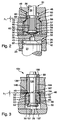
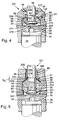
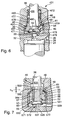
In der Zeichnung sind sechs Ausführungsbeispiele der Erfindung dargestellt, sie werden in der nachfolgenden Beschreibung näher erläutert. Es zeigen Figur 1 eine schematische Darstellung einer Kraftstoffeinspritzvorrichtung mit Kraftstoffversorgung aus einem Kraftstoffhochdruckspeicher und einem Kraftstoffeinspritzventil bekannter Bauart, Figur 2 ein erstes Ausführungsbeispiel der Erfindung mit einem Steuerventilglied, auf dem ein Schleppventilglied angeordnet ist, das durch einen Mitnehmer am Ventilstößel von seinem Ventilsitz wegbewegt wird, Figur 3 eine Abwandlung des Ausführungsbeispiels nach Figur 2 mit einem Steuerventilglied, das eine verbesserte Führung aufweist, Figur 4 ein drittes Ausführungsbeispiel der Erfindung in Weiterbildung zum Ausführungsbeispiel nach Figur 2, wobei statt eines Mitnehmers zur Mitnahme des Schleppventilglieds eine Druckfeder vorgesehen ist, Figur 5 ein viertes Ausführungsbeispiel der Erfindung bei dem am Schleppventilglied ein dritter Ventilsitz vorgesehen ist, Figur 6 ein fünftes Ausführungsbeispiel mit einem Steuerventilglied, das sowohl den Abflußquerschnitt vom Ventilraum zum Abflußkanal als auch den Verbindungskanal zwischen Ventilraum und Steuerraum steuert, und Figur 7 ein sechstes Ausführungsbeispiel, bei dem das Steuerventil in analoger Ausgestaltung zur Figur 2 den Druck eines Steuerraumes mit Hilfe einer 3/2-Ventilgestaltung steuert, wobei vom Ventilraum unverschließbar eine Verbindung zum Steuerraum besteht und koaxial zum Steuerventilglied ein Hochdruckzufluß zum Steuerraum vorgesehen ist, der durch eine Extremstellung des Steuerventilglieds verschließbar ist.In the drawing, six embodiments of the Invention shown, they are in the following Description explained in more detail. 1 shows a schematic representation of a Fuel injector with fuel supply off a high pressure fuel accumulator and one Fuel injection valve of a known type, FIG. 2 first embodiment of the invention with a Control valve member on which a drag valve member is arranged is that by a driver on the valve lifter of his Valve seat is moved away, Figure 3 shows a modification of the Embodiment of Figure 2 with a Control valve member having improved guidance Figure 4 shows a third embodiment of the invention in Further development of the embodiment of Figure 2, wherein instead of a driver for taking the drag valve member a compression spring is provided, Figure 5 is a fourth Embodiment of the invention in the Drag valve member a third valve seat is provided, Figure 6 shows a fifth embodiment with a Control valve member that both the discharge cross section from Valve space to the drainage channel as well as the connecting channel controls between valve space and control space, and Figure 7 sixth embodiment in which the control valve in analogous configuration to Figure 2, the pressure of a Controls the control room with the help of a 3/2-valve design, whereby a connection to the valve chamber cannot be closed Control room exists and coaxially to the control valve member High pressure flow to the control room is provided by an extreme position of the control valve member can be closed is.
Eine Kraftstoffeinspritzeinrichtung, mit der bei hohen Einspritzdrücken mit geringem Aufwand eine große Variation der Kraftstoffeinspritzung bezüglich Einspritzmenge und Einspritzzeitpunkt möglich ist, wird durch ein sogenanntes Common Rail System verwirklicht. Dieses stellt eine andere Art von Kraftstoffhochdruckquelle zur Verfügung als es durch die üblichen Kraftstoffhochdruckeinspritzpumpen gegeben ist. Dabei ist jedoch die Erfindung prinzipiell auch bei konventionellen Kraftstoffeinspritzpumpen verwendbar. Besonders vorteilhaft ist die Verwendung jedoch bei einem Common Rail Einspritz-System.A fuel injector with which at high Injection pressures a large variation with little effort the fuel injection with respect to the injection quantity and Injection time is possible is through a so-called Common Rail System implemented. This represents another Kind of high pressure fuel source available as it through the usual high pressure fuel injection pumps is given. However, the invention is also in principle conventional fuel injection pumps can be used. However, use with one is particularly advantageous Common rail injection system.
Bei dem in Figur 1 dargestellten Common Rail-Einspritzsystem
ist als Kraftstoffhochdruckquelle ein
Kraftstoffhochdruckspeicher 1 vorgesehen, der von einer
Kraftstoffhochdruckförderpumpe 2 aus einem
Kraftstoffvorratsbehälter 4 mit Kraftstoff versorgt wird.
Der Druck in dem Kraftstoffhochdruckspeicher 1 wird durch
einen Drucksensor 6 erfaßt und einer elektrische
Steuereinrichtung 8 zugeführt, die über ein
Drucksteuerventil 5 den Druck im Kraftstoffhochdruckspeicher
steuert. Die Steuereinrichtung steuert ferner auch das
Öffnen und Schließen von Kraftstoffhochdruckeinspritzventile
9, die zur Einspritzung von Kraftstoff vom Kraftstoffhochdruckspeicher
versorgt werden.In the common rail injection system shown in FIG. 1
is a high pressure fuel source
High-
In einer bekannten Ausgestaltung weist das
Kraftstoffeinspritzventil 9 ein Ventilgehäuse 11 auf, das an
seinem einen Ende, das zum Einbau an der Brennkraftmaschine
bestimmt ist, Einspritzöffnungen 12 besitzt, deren Austritt
aus dem Innern des Kraftstoffeinspritzventils durch ein
Einspritzventilglied 14 gesteuert wird. Dieses ist im
ausgeführten Beispiel als langgestreckte Ventilnadel
ausgebildet, die an ihrem einen Ende eine konische
Dichtfläche 15 besitzt, die mit einem innenliegenden
Ventilsitz am Ventilgehäuse zusammenwirkt, von dem aus die
Einspritzöffnungen 12 abführen. Die Ventilnadel ist in einer
Längsbohrung 13 an ihrem oberen, der Dichtfläche 15
abgewandten Ende geführt und wird am der Dichtfläche 15
abgewandten, aus der Längsbohrung 13 heraustretenden Ende
durch eine Druckfeder 18 in Schließrichtung beaufschlagt.
Zwischen der Führung in der Längsbohrung 13 und dem
Ventilsitz ist die Ventilnadel 14 von einem Ringraum 19
umgeben, der in einen Druckraum 16 mündet, welcher wiederum
über eine Druckleitung 17 in ständiger Verbindung mit dem
Kraftstoffhochdruckspeicher 1 steht. Im Bereich dieses
Druckraumes weist die Ventilnadel 14 eine Druckschulter 20
auf, über die sie vom Druck im Druckraum 16 entgegen der
Kraft der Feder 18 beaufschlagt wird im Sinne eines Abhebens
der Dichtfläche 15 vom Ventilsitz.In a known embodiment, the
Die Ventilnadel wird weiterhin durch einen Stößel 21
beaufschlagt, dessen der Ventilnadel 14 abgewandte
Stirnseite 22 in einer Stößelführungsbohrung 23 einen
Steuerraum 24 begrenzt. Dieser ist über einen Zulaufkanal
26, in dem eine Zulaufdrossel 28 vorgesehen ist, ständig mit
der Druckleitung 17 beziehungsweise dem
Kraftstoffhochdruckspeicher 1 verbunden. Der Zulaufkanal
mündet seitlich unverschließbar in den Steuerraum 24 ein.
Koaxial zum Stößel 21 führt vom Steuerraum 24 ein
Verbindungskanal 29 ab, der in einen Ventilraum 30 eines
Steuerventils 31 mündet. In dem Verbindungskanal, der
zugleich auch einen Abflußkanal darstellt, ist eine
Durchmesserbeschränkung, vorzugsweise in Form einer
Abflußdrossel 32 vorgesehen. Der nähere Aufbau des
Steuerventils 31 ist in den verschiedenen
Ausführungsbeispielen 2 bis 7 detaillierter dargestellt.
Diesen Ausführungsbeispielen ist gemeinsam, daß das
Steuerventil 31 ein Steuerventilglied 34 aufweist, bestehend
aus einem Ventilstößel 35, der in einer Stößelbohrung 36
geführt ist, und einem Ventilkopf 37 an dem in den
Ventilraum 30 ragenden finde des Steuerventilglieds 34. An
dem dem Ventilkopf gegenüberliegenden Ende des Ventilstößels
35 ist eine Federteller 38 vorgesehen, an dem sich eine
Druckfeder 39 abstüzt, die bestrebt ist, das
Steuerventilglied in Schließstellung zu bringen. In
entgegengesetzter Richtung wird das Steuerventilglied 34
durch einen Kolben 40 beaufschlagt, der Teil eines
Piezoaktors 41 ist und bei Erregen des Piezos je nach Grad
der Erregung das Steuerventilglied in verschiedene
Öffnungsstellungen bringen kann. Dabei kann der Kolben
direkt mit dem Piezo des Piezoaktors verbunden sein oder
mittels einer hydraulischen oder mechanischen Übersetzung
von diesem bewegt werden.The valve needle continues to be driven by a
Zur genaueren Darstellung der erfindungsgemäßen
Ausgestaltung des Sternerventils 31 wird dieses anhand von
Figur 2 näher beschrieben. Dort ist wiederum das Ende des
Stößel 21, der die Ventilnadel 14 betätigt, dargestellt. Der
Stößel 21 schließt in der Stößelführungsbohrung 23 mit
seiner als bewegliche Wand dienenden Stirnseite 22 den
Steuerraum 24 ein. Die Verstellung des Stößels 21 wird nach
oben hin durch einen Anschlag 42 begrenzt, der einen
außenliegenden Ringraum 43 freiläßt, in den der Zulauf 26
mündet. Axial führt im Bereich des Anschlags 42 der
Verbindungskanal 29 ab, der die Abflußdrossel 32 enthält und
in den Ventilraum 30 mündet. Dieser hat eine
kreiszylindrische Umfangswand 45, die über einen konischen
Ventilsitz 46 in einen den Ventilstößel 35 umgebenden
Ringraum 48 übergeht. Von diesem führt ein Abflußkanal 49 zu
einem Kraftstoffrücklauf oder einem Entlastungsraum ab.For a more precise representation of the invention
Design of the
Der am Ende des Ventilstößels 35 angeordnete Ventilkopf 37
weist eine konische dem Eintritt des Verbindungskanals 29 in
den Ventilraum 30 abgewandte Ventilkopfdichtfläche 51 auf,
die mit einem Vorventilsitz 52 unter Bildung eines
Vorventils 58 zusammenwirkt. Dieser Vorventilsitz 52
befindet sich am Übergang zu einer inneren Durchgangsbohrung
53 eines hülsenförmigen Schleppventilglieds 54, das den
Ventilstößel mit Abstand umgibt. Die innere Umfangswand der
inneren Durchgangsbohrung 53 bildet somit zusammen mit der
Mantelfläche 55 des Ventilstößels 35 einen
Durchtrittsquerschnitt 56. Zur Festlegung der Lage des
hülsenförmigen Schleppglieds 54 ist diese über
Abstandsrippen 57 am Ventilstößel 35 geführt. Diese Rippen
lassen den ausreichend bemessenen Durchtrittsquerschnitt 56
frei.The
An dem Vorventilsitz 52 axial gegenüberliegenden Ende weist
das hülsenförmige Schleppglied 54 eine
Ventilglieddichtfläche 59 auf, die ebenfalls konisch
ausgebildet ist, mit einem kleineren Konusspitzenwinkel als
der Konusspitzenwinkel des konischen Ventilsitzes 46 und mit
dem Ventilsitz 46 zusammenwirkt. Dabei stellt der konische
Ventilsitz 46 einen Hauptventilsitz eines Hauptvenils 61
dar, der einen wesentlich größeren Durchtrittsquerschnitt
vom Ventilraum 30 zum Ringraum 48 begrenzt als der
Durchtrittsquerschnitt der zwischen Ventilkopf 37 und
Vorventilsitz 52 des Vorventils 58 begrenzt wird. Weiterhin
sind zur besseren Führung des hülsenförmigen
Schleppventilglieds zwischen diesem und der Umfangswand 45
des Ventilraumes 30 ebenfalls Langsrippen 60 mit dazwischen
liegenden Nuten vorgesehen, die einen ausreichend großen
Durchtrittsquerschnitt 56 zum Hauptventil 61 freilassen.On the
In Figur 2 ist das Steuerventil 31 in Schließstellung
gezeigt, dabei ist der Ventilkopf 37 mit seiner Dichtfläche
51 zur Anlage an dem Vorventilsitz 52 gelangt und hat über
diesen das hülsenförmige Schleppventilglied 54 mit dessen
Schleppventildichtfläche 59 zur Anlage an dem
Hauptventilsitz 46 gebracht, so daß eine Verbindung zwischen
Ventilraum 30 und Ringraum 48 beziehungsweise Abflußkanal 49
unterbunden ist.In Figure 2, the
In dieser Schließstellung des Steuerventilglieds wird der
Steuerraum 24 durch den ständigen Zufluß von
Kraftstoffhochdruckmengen auf den Druck des
Kraftstoffhochdruckspeichers 1 gehalten, was bewirkt, daß
der Stößel 21 das Einspritzventilglied 14 in seiner
Schließstellung auf dem Ventilsitz hält. Dies ergibt sich
daraus, daß die Fläche der beweglichen Wand 22 wesentlich
größer ist als die Fläche der mit dem selben Druck
beaufschlagten Druckschulter 20 des Einspritzventilglieds
14. Dieser hohe Druck im Steuerraum 24 beaufschlagt auch den
Ventilkopf 37 und das hülsenförmige Schleppglied 54 in
jeweils deren Schließrichtung.In this closed position of the control valve
Zur Einleitung einer Einspritzung wird der Piezoaktor
angesteuert der dadurch das Steuerventilglied um einen
Öffnungshub verstellt. Dabei wird zunächst das Vorventil 58
geöffnet, indem der Ventilkopf 37 von dem Vorventilsitz 52
abhebt. Es kann eine Teilmenge von Kraftstoff zum
Abflußkanal 49 über den Durchtrittsquerschnitt 56 aus den
Ventilraum bzw. Steuerraum abfließen. Dennoch bleibt der
Druck im Ventilraum 30 so groß, daß das Schleppventilglied
mit seiner Ventilglieddichtfläche in Schließstellung am
Hauptventilsitz 46 verbleibt. Erst wenn der Hub des
Steuerventilglieds so groß ist, daß ein Mitnehmer 63, der am
Ventilstößel 35 z.B. in Form eines U-förmigen Spannelements
befestigt ist, in Anlage an der Stirnfläche 64 des
hülsenförmigen Schleppventilglieds gelangt, wird dieses mit
der Weiterbewegung des Ventilstößels 35 von dem
Hauptventilsitz 46 abgehoben, so daß nun ein größerer
Abflußquerschnitt freigegeben wird zur Entlastung des
Ventilraums 30 beziehungsweise des Steuerraums 24. Mit
Abfall der Erregung des Piezoaktors gelangt der Ventilstößel
35 unter Einwirkung der Feder 39 zusammen mit dem
geschleppten hülsenförmigen Schleppventilglied 54 wieder in
die gezeigte Ausgangsschließstellung zurück.The piezo actuator is used to initiate an injection
controlled by the control valve member by one
Opening stroke adjusted. First, the
Der große Vorteil eines Piezoantriebs ist die Tatsache, daß
ein davon betätigtes Steuerventilglied entsprechend der
Erregung des Aktors in definierte Stellungen gebracht werden
kann. Somit lassen sich auch einfach und exakt
Einspritzungen in eine Vor- und in eine Haupteinspritzung
unterteilen. Für eine Voreinspritzung bedarf es bei der oben
vorgestellten Konstruktion des Kraftstoffeinspritzventils
nur einer geringen Entlastung des Steuerraums 24 so, daß das
Einspritzventilglied nur eine kurzzeitige Öffnung der
Einspritzöffnungen 12 bewirkt. Für eine Haupteinspritzung
dagegen muß zur Durchführung eines großen, schnellen Hubes
des Einspritzventilglieds 14 der Steuerraum 24 schnell und
wirksam entlastet werden. Je schneller das Einspritzventil
öffnen bzw. schließen kann, desto genauer wird die
Einspritzphase bestimmbar. Dadurch daß der Zulauf 26 die
Zulaufdrossel 28 enthält und diese kleiner ist als der
Querschnitt auf der Abflußseite des Steuerraums 24,
insbesondere der Querschnitt der Abflußdrossel 32, kann die
wirksame Entlastung des Steuerraumes erzielt werden. Die
endgültige Steuerung des Querschnitts zum Abflußkanal 49 hin
übernimmt das Steuerventil. Dabei muß dieses zunächst gegen
den hohen Druck im Steuerraum 24 beziehungsweise im
Ventilraum 30 anarbeiten. Da nun aber der Abflußquerschnitt
am Vorventil 58 im Verhältnis zum Hauptventil 61 klein ist,
wird eine relativ geringe Arbeit für das Öffnen des
Vorventils 58 erforderlich. Durch das Öffnen des Vorventils
wird der Druck im Ventilraum 30 bereits wesentlich abgebaut,
so daß dann, wenn eine größere vom Druck im Ventilraum 30
beaufschlagte Wand gegen diesen Druck verstellt werden muß,
die aufzuwendende Kraft bereits geringer ist. Mit dieser
geringeren als bei einstufigem Öffnen erforderlichen Kraft
wird der Querschnitt des Hauptventils schnell geöffnet, was
zu einer entsprechend schnellen Entlastung von Ventilraum
und Steuerraum führt. Die Steuerung des Steuerventils kann
dabei so erfolgen, daß mit dem Öffnen des Vorventils 58 der
Druck im Steuerraum 24 bereits so abgesenkt wird, daß ein
kurzer Öffnungshub des Einspritzventilglieds 14 ermöglicht
ist. Daran anschließend kann das Steuerventilglied 35
nochmals weiterbewegt werden und über das Schleppventilglied
54 den größeren Abflußquerschnitt aufsteuern, um mit der
dann folgenden schnellen Entlastung die Öffnung des
Einspritzventilglieds 14 zur Haupteinspritzung zu
initiieren. Die Beendigung der Haupteinspritzung wird durch
Schließen des Steuerventils gesteuert und somit auch die
Einspritzmenge.The great advantage of a piezo drive is the fact that
a actuated control valve member according to the
Excitation of the actuator can be brought into defined positions
can. This makes it easy and exact
Injections into a pre and a main injection
divide. A pre-injection is required for the above
featured fuel injector design
only a slight relief of the
In einer alternativen Ausgestaltung der Ansteuerung des
erfindungsgemäßen Steuerventils kann der Druck nach dem
Öffnen des Vorventils nur soweit entlastet werden, daß das
Einspritzventilglied 14 noch geschlossen bleibt, aber eine
nur noch geringere weitere Entlastung ein Öffnen desselben
bewirkt. Durch eine anschließende weitere Verstellung des
Ventilstößels 35 kann dann durch die Vergrößerung des
Öffnungsgrades des Vorventils und/oder durch geschlepptes
Öffnen des Schleppventilglieds eine kurze weitere Entlastung
des Druckes im Steuerraum 24 beziehungsweise Ventilraum 30
vorgenommen werden, zur Erzeugung einer Voreinspritzung und
anschließend durch Rücknahme des Ventilstößelhubes eine
Beendigung derselben. Dem folgt dann ein größerer
Ventilstößelhub, bei dem über das Schleppventilglied 54
wiederum eine volle Entlastung des Steuerraums 24 zur
Durchführung der Haupteinspritzung bewirkt wird.In an alternative embodiment of the control of the
control valve according to the invention, the pressure after
Opening the valve should only be relieved to the extent that
Mit Hilfe des Hubes h1 des Ventilstößel 35, der notwendig
ist, damit der Mitnehmer 63 zur Anlage an der Stirnseite 64
des Schleppventilglieds 54 gelangt, kann der Öffnungshub des
Vorventils definiert werden. Die Stirnseite 64 ist dabei so
gestaltet, daß auch bei Anlage des ringförmigen Mitnehmers
63 der ausreichende Durchtrittsquerschnitt 56 vom Ventilraum
30 zum Ringraum 48 zur Verfügung steht. Dabei kann die
Stirnseite zum Beispiel kronenartig ausgeführt werden, mit
radialen Durchtrittsquerschnitten. Die Begrenzung des
Ablaufquerschnittes durch die Ablaufdrossel 32, die im
ausgeführten Beispiel im Verbindungskanal 29 angeordnet ist,
kann auch an einer anderen Stelle folgen, zum Beispiel im
Ablaufkanal 49 oder durch Dimensionierung eines maximalen
Durchflußquerschnittes 56 dazwischen.With the help of the stroke h1 of the
Den Figuren 8a bis 8c sind die Steuerabläufe dieses
Steuerventils zu entnehmen. In Figur 8a ist der Hub des
Einspritzventilglieds 14 über den Drehwinkel der
Brennkraftmaschine beziehungsweise der Zeit aufgetragen. Man
erkennt den kleineren Vorhub V der Einspritzventilnadel 14
zur Durchführung der Voreinspritzung, die dazwischenliegende
Pause P, bei dem das Steuerventil ganz oder soweit
geschlossen wird, daß sich ein das Einspritzventilglied
wieder in Schließstellung bringender Druck im Steuerraum 24
einstellt, und dem daran anschließenden Hub H, über dessen
Dauer die Haupteinspritzung definiert ist. Ausgelöst wird
dies durch die in der darunterliegenden Folge dargestellten
Hübe des Steuerventilglieds. Man erkennt den Hub V1, durch
den bei Erreichen der Maximalöffnungsposition beim Hub h1
des Stößels 35 , bevor also zum Beispiel das
Schleppventilglied vom Hauptventilsitz abgehoben wird, der
Steuerraum 24 so entlastet ist, daß der Hub des
Einspritzventilglieds 14 für den Hub V beginnen kann. Über
den Hub V1 bleibt die Entlastung zur Voreinspritzung
bestehen. In der Betätigungspause P1 des Steuerventilglieds,
d.h. bei nicht erregtem Piezo bleibt das
Einspritzventilglied 14 geschlossen. Am Ende von P1 beginnt
die Wiederbetätigung des Steuerventilglieds 35 durch den
Piezo bis zu einem Hub h2, in dem der gesamte
Absteuerquerschnitt nach Öffnen des Hauptventils 61 durch
das Schleppventilglied 54 aufgesteuert ist und der
Steuerraum 24 maximal entlastet ist. Bereits im Bereich
zwischen h1 und h2 öffnet das Einspritzventilglied und
bleibt über die Lange des Geöffnetseins des Steuerventils in
Offenstellung, so lange, bis bei der Schließbewegung des
Steuerventilglieds wieder der Druck im Steuerraum 24
unterschritten wird, der in der Lage ist das
Einspritzventilglied geöffnet zu halten.Figures 8a to 8c are the control processes of this
Control valve. In Figure 8a the stroke of the
In dem darunterliegenden Diagramm 8c wird der Druckverlauf
im Steuerraum 24 dargestellt mit entsprechenden
Druckeinbrüchen dann, wenn gemäß Diagramm 8b das
Steuerventilglied h1 geöffnet hat.The diagram 8c below shows the pressure curve
shown in the
Eine Modifikation des Steuerventils gemäß Figur 2 wird in
Figur 3 dargestellt. Soweit diese Ausgestaltung mit Figur 2
übereinstimmt, werden die gleiche Bezugsziffern verwendet.
Es wird hierzu auf die entsprechende Beschreibung zu Figur 2
verwiesen. Abweichend von der Ausführung nach Figur 2 ist
bei Figur 3 in dem Bereich, in dem bei Figur 2 der
Ventilstößel 135 in der Stößelbohrung 36 geführt ist, eine
Hülse 166 auf dem Stößel 135 angeordnet. In der Figur 3 ist
diese Hülse axial zwischen einem Anschlag 167 und einer
Haltescheibe 168 am Stößel fixiert. Der Anschlag wird durch
eine Schulter des Stößels gebildet, die am Ende der aus den
hülsenförmigen Schleppglied 54 herausragenden Abstandsrippen
57 vorgesehen ist. Die Haltescheibe kann zum Beispiel als
Sprengring in eine Ringnut 69 des Stößels an seinem aus der
Stößelbohrung 136 herausragendem Ende verwirklicht sein.
Alternativ kann jedoch die Hülse auch auf den Stößel 135
aufgepreßt sein. Durch den Anschlag 167 wird ferner der Hub
h1 definiert, ab dem der Stößel, der sich zusammen mit der
Hülse 166 bewegt, zur Anlage an dem hülsenförmigen
Schleppglied 54 gelangt. Ferner besitzt die Hülse 166 an
ihrem unteren zum Schleppventilglied 54 weisenden Ende eine
Durchmesserreduzierung, mit der im Ersatz zu dem Ringraum 48
von Figur 2 hier wiederum ein Ringraum 148 gebildet wird,
der ständig in Verbindung mit dem Abflußkanal 49 steht. Das
Schleppglied 54 ist wie auch im vorigen Ausführungsbeispiel
nach Figur 2 an seiner Stirnfläche so gestaltet, daß einen
Überströmquerschnitt freigelassen wird, der in der
Größenordnung des Durchtrittsquerschnitt 56 liegt.A modification of the control valve according to FIG. 2 is shown in
Figure 3 shown. As far as this configuration with Figure 2
matches, the same reference numbers are used.
Reference is made to the corresponding description for FIG. 2
referred. Deviates from the embodiment according to FIG. 2
in Figure 3 in the area in which in Figure 2 the
Mit dieser Ausgestaltung ergibt sich der Vorteil, daß die
Führungsfläche innerhalb der Stößelbohrung 136 größer ist
und somit das Steuerventilglied exakter geführt wird. Da der
Stößel 135 zum Zusammenbau durch die innere
Durchgangsbohrung 53 hindurchgeführt werden muß, wäre einer
Vergrößerung des Führungsdurchmessers des Stößels im Bereich
der Stößelbohrung gemäß Figur 2 eigentlich eine Grenze
gesetzt. Durch die Hinzufügung der Hülse 166 kann dennoch
die Führungsfläche vergrößert werden, wobei die Hülse
nachträglich nach Auffädelung des Schleppventilglieds 54 auf
den Ventilstößel montiert wird. Der Außendurchmesser der
Hülse ist dabei größer als der Durchmesser der inneren
Durchgangsbohrung 53 des Schleppventilglieds und kleiner als
der Durchmesser des Ventilraums 30. This configuration has the advantage that the
Guide surface within the tappet bore 136 is larger
and thus the control valve member is guided more precisely. Since the
Eine weitere Variante eines Steuerventils in Abwandlung zum
Ausführungsbeispiel nach Figur 2 ist in Figur 4
wiedergegeben. Auch hier werden zwei unterschiedliche
Abflußquerschnitte des Abflußkanals aufeinander folgend
aufgesteuert. Wie auch in Figur 2 ist hier wiederum der von
dem Stößel 21 des Einspritzventilgliedes 14 begrenzte
Steuerraum 24 vorgesehen, der über den die Drossel 32
enthaltenen Verbindungskanal 29 mit dem Ventilraum 30
verbunden ist. In diesen Ventilraum ragt der Stößel 235 mit
dem Ventilkopf 237 und der Ventilkopfdichtfläche 251, die im
Schließzustand des Steuerventils in Anlage am Vorventilsitz
52 des hülsenförmigen Schleppventilglieds 54 ist, unter
Bildung des Vorventils 58. Über den Ventilkopf 237 wird
dieses zusätzlich mit ihrer Ventilglieddichtfläche 59 in
Anlage am Hauptventilsitz 46 des Hauptventils 61 gehalten.
Jenseits dieses Ventilsitzes 46 befindet sich wiederum der
Ringraum 48, der vom Stößel 235 durchdrungen ist und der in
ständiger Verbindung mit dem Ablaufkanal 49 ist. Wie auch in
den Ausführngsbeispielen nach Figur 2 und 3 ist das
hülsenförmige Schleppventilglied 54 an seinem Außenumfang
über Längsrippen 60, die durch zwischen diesen liegende Nute
gebildet sind, an der Umfangswand 45 des Ventilraums 30
geführt. Diese Längsrippen lassen den Durchflußquerschnitt
zum Hauptventil 61 hin frei. Die innere Durchgangsbohrung 53
des Schleppventilglieds 54 ist vom Ventilstößel 35
beabstandet, so daß ausgehend vom Vorventil ein
entsprechender Durchflußquerschnitt 56 zum Ringraum 48
beziehungsweise Abflußkanal 49 besteht.Another variant of a control valve in a modification to
The exemplary embodiment according to FIG. 2 is shown in FIG. 4
reproduced. Again, two are different
Drainage cross-sections of the drainage channel in succession
steered on. As in FIG. 2, the one from
limited the
Der Verbindungskanal 29 liegt dem Ventilkopf 237 koaxial
gegenüber und mündet dort in einer axialen Begrenzungswand
270 des Ventilraums 30. Der Einmündung des Verbindungskanals
29 gegenüberliegend ist der Ventilkopf 237 an seiner
Stirnseite mit einer Dichtfläche 271 versehen, die entweder
eben kegelförmig oder konisch sein kann. Entsprechend ist
der Bereich des Austritts des Verbindungskanals 29 an der
axialen Begrenzungswand 270 als Ventilsitz ausgebildet, so
daß der Verbindungskanal durch die Dichtfläche 271
verschlossen werden kann. Die axiale Begrenzungswand ist
somit als Ventilsitz eines dritten Ventils 279 mit dem
Ventilkopf 237 als Ventilglied ausgebildet.The connecting
Bei diesem Ventil folgt die Betätigung des Ventilstößels 235
so, daß zur Realisierung einer Voreinspritzung der
Ventilkopf 237 in einem Zug von seiner Anlage am
Vorventilsitz 52 wegbewegt wird, bis zur Anlage seiner
Dichtfläche 271 an dem Ventilsitz 270 des dritten Ventils
279 beziehungsweise an der axialen Begrenzungswand 270. Über
den Weg des Ventilkopfs erfolgt eine kurzzeitige Entlastung
des Ventilraums 30 und des Steuerraums 24, die bei
entsprechender Bemessung ausreichend ist, eine Öffnung des
Einspritzventilglieds 14 zur Durchführung einer
Voreinspritzung zu bewirken. Liegt der Ventilkopf 237 mit
seiner Dichtfläche 271 dicht an der axialen Begrenzungswand
270 an, ist also der Verbindungskanal 29 ganz geschlossen,
so kann sich der Druck im Ventilraum weiter entspannen,
währenddessen der Druck im Steuerraum 24 über den Zulauf 26
wieder aufgebaut wird, was ein Schließen der
Einspritzventilnadel 14 nachsichzieht. Die Druckentlastung
im Ventilraum 30 führt wiederum dazu, daß die
Rückführungskräfte einer im Ringraum 48 angeordneten
Druckfeder 272, die sich zwischen dem Gehäuse und der
ringraumseitigen Stirnseite des Schleppventilglieds 54
abstützt, überwiegt und das Schleppventilglied 54 der
Verstellung des Ventilkopfes 237 nachführt bis zur wiederum
dichten Anlage an dessen Ventilkopfdichtfläche 251. Wenn
dann in der Folge durch entsprechende Steuerung des
Piezoaktors der Ventilkopf in eine Zwischenstellung zwischen
den Ventilsitzen 270 und 46 bewegt wird, kann der Steuerraum
24 über den Ventilraum 30 und den großen Öffnungsquerschnitt
des Hauptventils 61 sehr schnell im vollen möglichen Umfang
entlastet werden, so daß hier zur Durchführung einer
Haupteinspritzung eine maximale, schnelle Verstellung des
Einspritzventilglieds in Öffnungsrichtung erfolgen kann. Die
Abkopplung des Steuerraums 24 von der Druckquelle 1 über die
Zulaufdrossel 28 erlaubt hier eine Entlastung auf nahezu
vollständigen Entlastungsdruck, begünstigt durch den großen
Abströmquerschnitt am Außenumfang des Schleppventilglieds.
Zur Beendigung der Haupteinspritzung wird der Ventilkopf
zusammen mit dem Schleppventilglied 54 wieder zurückgeführt,
unter dichtem Verschluß des Vorventils 58 und des
Hauptventils 61. Der große Vorteil bei dieser Ausgestaltung
besteht darin, daß zur Durchführung der Voreinspritzung nur
eine einzige Bewegung des Steuerventilglieds in einer
Richtung erforderlich ist und zur Durchführung der
Haupteinspritzung weiterhin nur eine Rückbewegung in Form
eines Teilhubes in Richtung Ausgangsstellung und einer sich
anschließenden endgültigen Rückführung.With this valve,
Während bei den Ausführungsbeispielen Figuren 2 und 3
jeweils nur zwei Ventile im Zusammenhang mit dem
Steuerventilglied und dem Schleppventilglied verwirklicht
wurden, waren im vorbeschriebenen Ausführungsbeispiel Figur
4 insgesamt drei Ventile verwirklicht, das Vorventil 58 mit
dem Vorventilsitz 52, das Hauptventil 61 mit dem
Hauptventilsitz 46 und das dritte Ventil 279 mit dem
Ventilsitz 270. In alternativer Ausgestaltung nach Figur 5
sind auch hier drei Ventile verwirklicht. Diese Ausführung
baut jedoch auf die Ausgestaltung nach Figur 3 auf. Wie in
Figur 3 ist auch hier wieder der Ventilraum 30 vorgesehen,
in dem koaxial zum Ventilstößel 35 der Verbindungskanal 29
vom Steuerraum 24 herkommend, einmündet.While in the exemplary embodiments FIGS. 2 and 3
only two valves each in connection with the
Control valve member and the drag valve member realized
were in the above-described
Es ist hier wieder am in den Ventilraum 30 ragenden Ende des
Stößels 335 der Ventilkopf 337 vorgesehen, mit der
Ventilkopfdichtflache 351, die mit dem Vorventilsitz 52 am
Schleppventilglied 354 unter Bildung des Vorventils 58
zusammenwirkt. Dieses hat wiederum an seinem dem Ventilkopf
337 abgewandten Ende außen zu seiner Umfangswand kegelförmig
geneigt oder kugelförmig angeordnet die
Ventilglieddichtfläche 59, die mit dem Hauptventilsitz 46
unter Bildung des Hauptventils 61 am Übergang zwischen
Ventilraum 30 zum Ringraum 48 zusammenwirkt. Das
Schleppventilglied ist am Außenumfang durch Längsrippen 60
an der Umfangswand des Ventilraumes geführt. Auch ist auf
dem Ventilstößel 335 eine Hülse 366 aufgepreßt, die einen
vergrößerten Außenumfang bereithält, über den der
Ventilstößel in der Stößelbohrung 336 geführt wird. Diese
Hülse 366 ragt in den mit dem Abflußkanal 49 verbundenen
Ringraum 48 hinein und überragt dort eine Ringnut 374 des
Stößels 335, die axial von der Ventilkopfdichtfläche des
Ventilkopfes 337 begrenzt ist und den radialen Abstand zur
inneren Durchgangsbohrung 53 des Schleppgliedes 54 hält und
somit den Durchflußquerschnitt 56 bildet. Die Hülse 366 hat
nun in ihrem die Ringnut 374 überlappenden Bereich
stirnseitig eine kegelförmige Dichtfläche 375, die bei
entsprechender Bewegung des Ventilstößels 335 zur Anlage auf
einen kegelförmigen Ventilsitz 376 an der Stirnseite des
Schleppventilglieds 354 bringbar ist. Dieser Ventilsitz 376
bildet somit zusammen mit der kegelförmigen Dichtfläche 375
ein drittes Ventil 379. Der kegelförmige Ventilsitz 376 ist
dabei zum Innern der inneren Durchgangsbohrung 53 des
Schleppventilglieds 354 hin geneigt, also in Gegenrichtung
der Neigung der Ventilglieddichtflache 59 des Hauptventils
61.It is here again at the end of the projecting into the
In der gezeigten Schließstellung des Steuerventils wird der
Ventilkopf mit seiner Ventilkopfdichtfläche in Anlage an dem
Vorventilsitz 52 gebracht und weiterhin das
Schleppventilglied 354 mit seiner Ventilglieddichtfläche 59
in Anlage an den Hauptventilsitz 46 gebracht. Damit ist die
Verbindung zwischen dem Ventilraum 30 und dem Ablaufkanal 49
unterbunden und es kann der Steuerraum 24 auf den von der
Druckquelle vorgegebenen hohen Druck gebracht werden, mit
dem Erfolg des Schließens des Einspritzventilglieds 14. Bei
einer anschließenden Betätigung des Steuerventils zur
Durchführung einer Voreinspritzung wird der Stößel 335 mit
der Hülse 366 soweit bewegt, daS die kegelförmige
Dichtfläche 375 der Hülse 366 in dichter Anlage an den
kegelförmigen Ventilsitz 376 des Schleppventilglieds 354
gelangt. Über diesen Hub h5 erfolgt eine kurzzeitige
Entlastung des Ventilraums 30 und des Steuerraums 24, die
ausreicht, das Einspritzventilglied 14 in eine
Voreinspritzstellung zu bewegen. Mit Schließen des dritten
Ventils 379 durch Anlage der Dichtfläche 375 an den
kegelförmigen Ventilsitz 376 nach Zurücklegen des Hubes h5,
wird durch Druckaufbau im Steuerraum 24 die Voreinspritzung
beendet. Für die Haupteinspritzung wird nachfolgend das
Steuerventilglied weiterbewegt. Dadurch wird das
Schleppventilglied 354 vom Hauptventilsitz 46 abgehoben, so
daß es zu einer vollen maximalen Entlastung des Steuerraums
24 kommt. Für diese Entlastung steht ein wesentlich größerer
Querschnitt zur Verfügung, als der der zur Durchführung der
Voreinspritzung zur Verfügung stand, durch Öffnen des
Vorventils bis Schließen des dritten Ventils. Der Vorteil
bei dieser Ausgestaltung besteht darin, daß durch eine
gestufte Bestromung des Piezoaktors dieser für die Vor- und
Haupteinspritzung in nur eine Richtung geschaltet werden
muß. Es ergeben sich dabei sehr kurze Schaltzeiten,
insbesondere ist durch das Durchschalten von dem einen
Ventilsitz 52 zum anderen Ventilsitz 376 eine sehr kurze
Entlastung und damit eine sehr kleine Voreinspritzmenge
verwirklichbar. Zur Beendigung der Einspritzung wird der
Stößel in die gezeigte Ausgangsstellung zurückgebracht. Für
jeden Einspritzvorgang steht ein separater
Entlastungsquerschnitt zur Verfügung, der den entsprechenden
Erfordernissen angepaßt werden kann.In the closed position of the control valve shown, the
Valve head with its valve head sealing surface in contact with the
Brought
Ein fünftes Ausführungsbeispiel der Erfindung ist in Figur 6
dargestellt, das eine Weiterentwicklung des
Ausführungsbeispiels nach Figur 4 darstellt. Wie beim
Ausführungsbeispiel nach Figur 4 sind in Zusammenwirkung von
Ventilkopf 437 und Schleppventilglied 454 drei Ventile
verwirklicht. Wie auch bei Figur 4 mündet wiederum der
Verbindungskanal 29 koaxial zum Ventilstößel 435 in den
Ventilraum 30 ein. Wie auch beim Ausführungsbeispiel nach
Figur 4 ist die axial gerichtete Wand 470 des Ventilraums 30
am Eintritt des Verbindungskanals 29 als Ventilsitz des
dritten Ventils 479 ausgebildet, an dem die als Dichtfläche
ausgebildete Stirnseite 471 des Ventilkopfes 437 in Anlage
bringbar ist. Der Ventilkopf 437 trägt die
Ventilkopfdichtfläche 51, die mit dem Vorventilsitz 52 am
Übergang von der Stirnseite des Schleppventilglieds 454 zu
seiner inneren Durchgangsbohrung 53 unter Bildung des
Vorventils 58 zusammenwirkt. Am gegenüberliegenden Ende
trägt das Schleppventilglied 454 eine kegelförmige
Ventilglieddichtfläche 459, die mit dem Hauptventilsitz 46
am Übergang des Ventilraums 30 zu dem Ringraum 48 unter
Bildung des Hauptventils 61 zusammenwirkt. Wie auch beim
Ausführungsbeispiel nach Figur 4 ist das Schleppventilglied
454 durch eine Druckfeder 472 in Richtung eines Öffnen des
Hauptventils 61 belastet. Dabei setzt die Feder 472 über
eine Druckscheibe 477 an einer stutzenförmigen Verlängerung
478 des Schleppventilglieds 54 an. Im Bereich dieser
stutzenförmigen Verlängerung 478 wird das Schleppventilglied
454 dicht auf dem Außenmantel 455 des Ventilstößels 435
geführt, so, daß zwischen dem Ventilkopf 437 und dem
Schleppventilglied 454 eine Ringausnehmung 480
eingeschlossen ist, die über eine durch das
Schleppentilglied führende Drosselbohrung 481 in ständiger
Verbindung mit dem Ringraum 48 steht.A fifth exemplary embodiment of the invention is shown in FIG. 6
shown that a further development of
Representing embodiment of Figure 4. As with
Embodiment according to Figure 4 are in cooperation of
Bei dieser Ausgestaltung sind somit drei Drosseln
verwirklicht, zum einen ist das die Zulaufdrossel 28 im
Zulauf 26 zum Steuerraum 24, zum zweiten ist es die
Abflußdrossel 32 im Verbindungskanal 29 und zum dritten die
oben erwähnte Drosselbohrung 81.In this embodiment, there are three chokes
realized, on the one hand, the
Wie beim Ausführungsbeispiel nach Figur 4 wird zur Erzielung
einer Voreinspritzung das Steuerventilglied so betätigt, daß
der Ventilkopf 437 vom Vorventilsitz 52 abgehoben wird und
durchbewegt wird bis zur Anlage seiner Dichtfläche 471 am
Ventilsitz 470 des dritten Ventils 479. Über diese
Bewegungsdauer erfolgt eine kurze Entlastung des Steuerraums
24, die bestimmt ist durch den Querschnitt der
Drosselbohrung 481 als einzige Verbindung zwischen
Steuerraum 24 und Ringraum 48 bei zunächst noch am
Hauptventilsitz 46 anliegendem Schleppventilglied.
Anschließend in der Schließstellung des dritten Ventils 479
in Anlage an der axialen Begrenzungswand 470 des Ventilraums
30 wird der Ventilraum über die Drosselbohrung 481 weiter
entlastet. Es entsteht dabei im Ventilraum 30 ein
Entlastungsdruck, der es erlaubt, das Schleppventilglied 454
durch die Feder 472 von dem Hauptventilsitz 46 weg zur
Anlage auf die Ventilkopfdichtfläche 51 des Ventilkopfes
bewegt wird. Damit wird aber auch das Hauptventil 61
geöffnet, so daß sich der Steuerraum 30 weiterhin entlasten
kann. Zur Durchführung der Haupteinspritzung wird darauf
wiederum der Ventilkopf 437 zusammen mit dem
Schleppventilglied 454 in eine Zwischenstellung bewegt, in
der der große Verbindungsquerschnitt des Hauptventils 61
zwischen dem Abflußkanal 49 und dem Steuerraum 24 geöffnet
ist. As in the embodiment of Figure 4 is to achieve
a pilot injection actuates the control valve member so that
the
Abweichend von der Ausführungsform nach Figur 4 bietet sich
hier die Möglichkeit eines gezielten Einsatzes von Drosseln
zur Bestimmung der Entlastungsdynamik des Steuerraums 24.
Zur Durchführung der Voreinspritzung wird die Entlastung
durch die Drosselbohrung 481 bestimmt und bei der
Haupteinspritzung wird die Entlastung des Steuerraums 24
durch die größere Abflußdrossel 32 bestimmt, die kleiner ist
als der Abströmquerschnitt des Hauptventils 61. Zusammen mit
der Zulaufdrossel 29 stellt sich dann zur Definition der
Haupteinspritzung in der gewünschten Gradation der Druck im
Steuerraum 24 ein. Die Haupteinspritzung wird schließlich
durch Zurückbewegen des Stößels 435 in die gezeigte
Ausgangsstellung von Figur 6 erzielt, bei der das Vorventil
58 und das Hauptventil 61 geschlossen sind und das dritte
Ventil 479 geöffnet ist. Man kann auf diese Weise im
Endhubbereich der Ventile den Toleranzeinfluß des
Ventilhubes minimieren. Die Querschnitte können für die Vor- und
Haupteinspritzung individuelle angepaßt werden.Deviating from the embodiment according to FIG. 4 offers itself
here the possibility of a targeted use of chokes
to determine the relief dynamics of the
Im Diagramm, Figur 9a bis 9c ist aufgezeichnet, wie der
Bewegungsabläufe der Einspritzventilnadel 14, des
Ventilkopfes 437 und des Schleppventilglieds 454 ausgebildet
sind. Im oben stehenden Diagramm 9a ist über den Hub und die
Zeit die Bewegung der Einspritzventilnadel aufgezeichnet,
mit einem kleinem Hub zur Voreinspritzung V, einer
dazwischenliegenden Pause P, in dem das Einspritzventil
geschlossen ist und einen anschließenden Haupteinspritzung
H. Ausgelöst wird die Voreinspritzung gemäß dem
darunterliegenden Diagramm 9b durch die Verstellung des
Ventilkopfes 437. Ausgehend von der Schließstellung gemäß
Figur 6 wird der Ventilkopf vom Vorventilsitz 52 durchbewegt
bis zur Anlage am Ventilsitz 470 des dritten Ventils, was in
dem Diagramm durch die Zahl 470 an der Ordinate dargestellt
ist. Zu diesem Zeitpunkt ist der Steuerraum 24 wieder
verschlossen, so daß sich über die Pause, in dem auch das
dritte Ventil 479 verschlossen ist, der hohe Schließdruck im
Steuerraum 24 einstellt und das Einspritzventilglied 14
geschlossen hält. In diesem Zeitraum bewegt sich aber gemäß
Diagramm 9c das Schleppglied 454 ab Verschließen des dritten
Ventils 479 bis zur Anlage am Ventilkopf 437. Diese Position
wird in dem Diagramm mit der Zahl 52 an der Abszisse
dargestellt. Nach Anlage verharrt auch das
Schleppventilglied 454 in dieser Endstellung bis zum Ende
der Pause P. Dann wird das Steuerventilglied wieder zurück
in eine Zwischenstellung bewegt wird. Hierbei bewegen sich
der Ventilkopf 437 und das Schleppventilglied synchron in
eine Zwischenstellung Z, die zur vollen Entlastung des
Steuerraumes 24 führt. Mit der Rückführung von Ventilkopf
437 und Schleppventilglied 454 wird schließlich die
Entlastung des Steuerraumes 24 wieder unterbrochen und es
baut sich der das Schließen des Einspritzventilglied
bewirkende Steuerdruck wieder auf.In the diagram, Figure 9a to 9c is recorded as the
Motions of the
Im Vorstehenden wurden in verschiedenen Ausführungsformen
des Steuerventils dargestellt, daß zur Steuerung des Druckes
im Steuerraum 24 eine Verbindung zum Abflußkanal 49
hergestellt wird, was zu einer Entlastung des Steuerraums 24
führt. Zur Belastung des Steuerraums wird lediglich das
Steuerventil wieder in Schließstellung gebracht und der
ständige Zulauf von Kraftstoffhochdruck über den Zulaufkanal
26 eingestellt. Solche Ventile arbeiten im Prinzip als 2/2-Ventile.
Im Vorliegenden wurde ein solches 2/2-Ventil durch
das Schleppventilglied 54 modifiziert. Gemäß Figur 7 kann
ein solches Ventil aber auch als 3/2-Ventil ausgeführt
werden, wobei in einer ersten Stellung des Ventils eine
Verbindung vom Kraftstoffhochdruckspeicher vom Steuerraum
hergestellt wird unter gleichzeitigem Verschluß des
Abflußkanals und in einer zweiten Stellung des Ventils die
Verbindung zwischen Kraftstoffhochdruckspeicher 1 und
Steuerraum unterbunden werden, unter Herstellung der
Verbindung des Steuerraums zum Entlastungskanal. Figur 7
zeigt in diesem Zusammenhang eine sehr ähnliche
Ausgestaltung wie Figur 2 mit dem Unterschied, daß der
Ventilraum 530 über den Verbindungskanal 529 in ständiger
Verbindung mit dem hier nicht weiter gezeigten Steuerraum
steht. Dieser Verbindungskanal zweigt von der Umfangswand
des zylindrisch ausgebildeten Ventilraums 530 ab. Der Zulauf
von Hochdruckkraftstoff erfolgt hier an der axialen
Stirnwand 570 des Ventilraums 530, wobei dieser Zulauf 526
koaxial zur Achse des Ventilraums 530 beziehungsweise des
Stößels 535 einmündet. Die Stirnseite 570 bildet dabei im
Einmündungsbereich des Zulaufs 526 einen Ventilsitz, der mit
einer stirnseitigen Dichtfläche 571 am Ventilkopf 537 in
analoger Ausgestaltung zu Figur 4 als drittes Ventil 479,
hier jedoch in abweichender Funktion, zusammenwirkt. Wie
auch in den vorigen Ausführungsbeispielen ist der
Ventilstößel 535 in einer Stößelbohrung 36 geführt und
durchdringt den Ringraum 48, der wiederum über den
Hauptventilsitz 46 den im Durchmesser größeren Ventilraum
530 übergeht. Mit dem Hauptventilsitz 46 wirkt eine
Ventilglieddichtfläche 59 eines gleichermaßen wie bei Figur
2 ausgebildeten Schleppventilglieds 54 zusammen, wobei diese
Ventilglieddichtfläche konisch ausgebildet ist, analog dem
konischen Übergang zwischen Ventilraum 530 und Ringraum 48
und am einen Ende des hülsenförmigen Schleppventilglieds 54
zu dessen Außenumfang geneigt angeordnet ist. Am
gegenüberliegenden Ende des hülsenförmigen Ventilglieds 54
befindet sich wiederum zur inneren Durchgangsbohrung 53
geneigt eine kegelförmiger Vorventilsitz 52, der mit einer
Ventilkopfdichtfläche 551, die ebenfalls kegelförmig
ausgebildet ist, am Ventilkopf 537 zusammenwirkt. Im Bereich
des Ringraumes 48 weist der Ventilstößel 535 ferner einen
Mitnehmer 563, der zum Beispiel als Sprengring in eine
Ringnut 583 des Ventilstößel eingeklippst sein kann.
Befindet sich der Ventilkopf in Anlage an dem Vorventilsitz
52 des Vorventils 58 und die Ventilglieddichtfläche 59 in
Anlage am Hauptventilsitz 46 ds Hauptventils 61, ist der
Mitnehmer 563 um einen Hub h1 von einer Stirnseite 564 des
Schleppventilglieds beabstandet. Auch bei Anlage des
Mitnehmers 563 an der Stirnseite 564 bleibt genügend
Querschnitt frei, um ein Kraftstoffluß vom Ventilraum 530
bei geöffnetem Vorventil durch den zwischen Ventilstößel 535
und der inneren Durchgangsbohrung gebildeten
Durchtrittsquerschnitt 56 zum Ringraum 48 abfließen kann und
von dort über den Abflußkanal zur Entlastungsseite.The foregoing have been in various embodiments
of the control valve shown that to control the pressure
in the control room 24 a connection to the
Bei Betätigung des Ventilstößels 535 durch den Aktor kann
dieser mit dem Ventilkopf vom Vorventilsitz 52 abgehoben
werden, so daß unter gleichzeitigem Zufluß von Kraftstoff
über den Zulaufkanal 536 und Abfluß von Kraftstoff über den
Durchtrittsquerschnitt 56 zum Abflußkanal 49 sich im
Steuerraum ein mittlerer Druck einstellt, der ausreichend
ist, um eine Voreinspritzung durch Öffnen des
Einspritzventilglieds 14 zu bewirken. Für die
Haupteinspritzung wird das Steuerventilglied mit dem
Ventilkopf 537 durchgeschaltet bis zur Anlage der
Dichtfläche 571 am Ventilsitz 570 beziehungsweise Schließen
des dritten Ventils 579. Damit ist der Zulauf von
Hochdruckkraftstoff in den Ventilraum und damit auch in den
Steuerraum unterbunden und der Steuerraum kann zum
Abflußkanal 49 ganz entlastet werden. Im Laufe dieser
Bewegung ist zusätzlich der Mitnehmer 563 in Anlage an die
Stirnseite 564 gelangt und hat das Schleppventilglied 54 vom
Hauptventilsitz 46 abgehoben, so daß auch ein sehr großer
Entlastungsquerschnitt vom Steuerraum 24 zum Abflußkanal 49
hergestellt ist. Zur Beendigung der Haupteinspritzung wird
daraufhin der Ventilstößel mit Ventilkopf 537 wieder in die
gezeigte Ausgangsstellung zurückbewegt, bei der das dritte
Ventil 579 geöffnet und das Vorventil 58 und das Hauptventil
61 geschlossen sind. Es kann sich dann durch den zulaufenden
Hochdruckkraftstoff wieder der hohe Druck im Steuerraum
aufbauen und das Einspritzventilglied 14 in Schließstellung
bringen. In analoger Weise können bei einem solches 3/2-Steuerventils
auch analog die Ausgestaltungen nach Figuren 3
und 5 Anwendung finden.When the
Claims (22)
Applications Claiming Priority (2)
| Application Number | Priority Date | Filing Date | Title |
|---|---|---|---|
| DE19816316 | 1998-04-11 | ||
| DE19816316A DE19816316A1 (en) | 1998-04-11 | 1998-04-11 | Fuel injection device for internal combustion engines |
Publications (3)
| Publication Number | Publication Date |
|---|---|
| EP0949415A2 true EP0949415A2 (en) | 1999-10-13 |
| EP0949415A3 EP0949415A3 (en) | 2002-06-12 |
| EP0949415B1 EP0949415B1 (en) | 2004-10-13 |
Family
ID=7864365
Family Applications (1)
| Application Number | Title | Priority Date | Filing Date |
|---|---|---|---|
| EP98123745A Expired - Lifetime EP0949415B1 (en) | 1998-04-11 | 1998-12-14 | A fuel injection device for internal combustion engines |
Country Status (4)
| Country | Link |
|---|---|
| US (1) | US6085719A (en) |
| EP (1) | EP0949415B1 (en) |
| JP (1) | JPH11324848A (en) |
| DE (2) | DE19816316A1 (en) |
Cited By (8)
| Publication number | Priority date | Publication date | Assignee | Title |
|---|---|---|---|---|
| EP1016783A2 (en) * | 1998-12-28 | 2000-07-05 | Robert Bosch Gmbh | Fuel injection device for internal combustion engines |
| WO2000050761A1 (en) * | 1999-02-22 | 2000-08-31 | Siemens Aktiengesellschaft | Injector for an injection system of an internal combustion engine |
| WO2002008598A1 (en) * | 2000-07-22 | 2002-01-31 | Robert Bosch Gmbh | Method for controlling an injection valve for injecting fuel into an internal combustion engine |
| EP1041272A3 (en) * | 1999-04-01 | 2002-09-18 | Delphi Technologies, Inc. | Fuel injector |
| WO2004079180A1 (en) * | 2003-03-04 | 2004-09-16 | Siemens Aktiengesellschaft | Valve comprising a spring element for a fuel injector |
| WO2005095787A1 (en) * | 2004-03-23 | 2005-10-13 | Siemens Aktiengesellschaft | Servo valve and injection valve |
| EP1640604A1 (en) * | 2004-09-23 | 2006-03-29 | Siemens Aktiengesellschaft | Servo valve and injection valve |
| EP1781932A1 (en) * | 2004-08-24 | 2007-05-09 | Robert Bosch Gmbh | Control valve for an injection valve |
Families Citing this family (26)
| Publication number | Priority date | Publication date | Assignee | Title |
|---|---|---|---|---|
| DE19826791A1 (en) * | 1998-06-16 | 1999-12-23 | Bosch Gmbh Robert | Valve control unit for a fuel injector |
| DE19940292B4 (en) * | 1999-08-25 | 2008-03-06 | Robert Bosch Gmbh | Control valve for a fuel injection valve |
| DE19940300A1 (en) * | 1999-08-25 | 2001-03-01 | Bosch Gmbh Robert | Control valve for an injector |
| EP1081372B1 (en) * | 1999-08-31 | 2004-10-13 | Denso Corporation | Fuel injection device |
| DE19941463A1 (en) * | 1999-09-01 | 2001-03-15 | Bosch Gmbh Robert | Magnet injector for fuel storage injection systems |
| US20030155021A1 (en) * | 2000-01-22 | 2003-08-21 | Friedrich Boecking | Valve for the control of fluids |
| DE10015268A1 (en) * | 2000-03-28 | 2001-10-04 | Siemens Ag | Injector with bypass throttle |
| DE10031582A1 (en) * | 2000-06-29 | 2002-01-17 | Bosch Gmbh Robert | Pressure controlled injector with controlled nozzle needle |
| DE10031580A1 (en) * | 2000-06-29 | 2002-01-17 | Bosch Gmbh Robert | Pressure-controlled control part for common rail injectors |
| DE10031579A1 (en) * | 2000-06-29 | 2002-01-17 | Bosch Gmbh Robert | Pressure controlled injector with vario register injector |
| DE10046823B4 (en) * | 2000-09-20 | 2004-07-15 | L'orange Gmbh | Servo control valve for injection injectors |
| US6764028B2 (en) | 2001-04-04 | 2004-07-20 | Synerject, Llc | Fuel injector nozzles |
| US6634339B2 (en) | 2001-10-31 | 2003-10-21 | Caterpillar Inc | Front end rate shaping valve concept for a fuel injection system |
| DE10154802A1 (en) * | 2001-11-08 | 2003-05-22 | Bosch Gmbh Robert | Fuel injection device for an internal combustion engine |
| US7124744B2 (en) * | 2003-07-31 | 2006-10-24 | Caterpillar Inc. | Variable control orifice member and fuel injector using same |
| DE10335059A1 (en) * | 2003-07-31 | 2005-02-17 | Robert Bosch Gmbh | Switching valve for a fuel injector with pressure booster |
| ES2277229T3 (en) | 2004-06-30 | 2007-07-01 | C.R.F. Societa Consortile Per Azioni | SERVOVALVULA TO CONTROL THE FUEL INJECTOR OF AN INTERNAL COMBUSTION ENGINE. |
| EP1621764B1 (en) * | 2004-06-30 | 2007-11-07 | C.R.F. Società Consortile per Azioni | Internal combustion engine fuel injector |
| DE102006021741A1 (en) * | 2006-05-10 | 2007-11-15 | Robert Bosch Gmbh | Fuel injector with pressure compensated control valve |
| ATE445777T1 (en) * | 2007-07-30 | 2009-10-15 | Fiat Ricerche | INJECTOR WITH BALANCED GAUGE SERVO VALVE FOR AN INTERNAL COMBUSTION ENGINE |
| DE102008032385B4 (en) * | 2008-07-09 | 2018-03-29 | Audi Ag | High-pressure injection arrangement for a direct-injection internal combustion engine |
| DE102009001003B4 (en) * | 2009-02-19 | 2017-11-30 | Robert Bosch Gmbh | Fuel injector |
| DE102011017217A1 (en) | 2011-04-15 | 2012-10-18 | Mühlbauer Ag | Apparatus and method for depositing sheet products |
| CH710127A1 (en) * | 2014-09-17 | 2016-03-31 | Ganser Crs Ag | Fuel injection valve for internal combustion engines. |
| CN107002620B (en) | 2014-12-11 | 2019-06-25 | 德尔福国际业务卢森堡公司 | Control valve group |
| US10077748B2 (en) * | 2014-12-23 | 2018-09-18 | Cummins Inc. | Fuel injector for common rail |
Citations (1)
| Publication number | Priority date | Publication date | Assignee | Title |
|---|---|---|---|---|
| DE19624001A1 (en) | 1996-06-15 | 1997-12-18 | Bosch Gmbh Robert | Fuel injection device for internal combustion engines |
Family Cites Families (10)
| Publication number | Priority date | Publication date | Assignee | Title |
|---|---|---|---|---|
| JPH07145750A (en) * | 1993-11-25 | 1995-06-06 | Zexel Corp | Fuel injection control device |
| JP2885076B2 (en) * | 1994-07-08 | 1999-04-19 | 三菱自動車工業株式会社 | Accumulator type fuel injection device |
| JPH08158981A (en) * | 1994-12-02 | 1996-06-18 | Nippondenso Co Ltd | Fuel injection device |
| US5671715A (en) * | 1995-04-27 | 1997-09-30 | Nipon Soken, Inc. | Fuel injection device |
| EP0745764B1 (en) * | 1995-06-02 | 2001-03-21 | Ganser-Hydromag Ag | Fuel injection valve for internal combustion engines |
| JPH09209867A (en) * | 1996-02-07 | 1997-08-12 | Mitsubishi Motors Corp | Fuel injector |
| US5779149A (en) * | 1996-07-02 | 1998-07-14 | Siemens Automotive Corporation | Piezoelectric controlled common rail injector with hydraulic amplification of piezoelectric stroke |
| FI101739B (en) * | 1996-08-16 | 1998-08-14 | Waertsilae Nsd Oy Ab | An injection valve |
| JP3653882B2 (en) * | 1996-08-31 | 2005-06-02 | いすゞ自動車株式会社 | Engine fuel injector |
| DE19738397A1 (en) * | 1997-09-03 | 1999-03-18 | Bosch Gmbh Robert | Fuel injection system for an internal combustion engine |
-
1998
- 1998-04-11 DE DE19816316A patent/DE19816316A1/en not_active Withdrawn
- 1998-12-14 DE DE1998512121 patent/DE59812121D1/en not_active Expired - Lifetime
- 1998-12-14 EP EP98123745A patent/EP0949415B1/en not_active Expired - Lifetime
-
1999
- 1999-04-09 JP JP11103268A patent/JPH11324848A/en active Pending
- 1999-04-12 US US09/289,617 patent/US6085719A/en not_active Expired - Fee Related
Patent Citations (1)
| Publication number | Priority date | Publication date | Assignee | Title |
|---|---|---|---|---|
| DE19624001A1 (en) | 1996-06-15 | 1997-12-18 | Bosch Gmbh Robert | Fuel injection device for internal combustion engines |
Cited By (10)
| Publication number | Priority date | Publication date | Assignee | Title |
|---|---|---|---|---|
| EP1016783A2 (en) * | 1998-12-28 | 2000-07-05 | Robert Bosch Gmbh | Fuel injection device for internal combustion engines |
| EP1016783A3 (en) * | 1998-12-28 | 2002-10-23 | Robert Bosch Gmbh | Fuel injection device for internal combustion engines |
| WO2000050761A1 (en) * | 1999-02-22 | 2000-08-31 | Siemens Aktiengesellschaft | Injector for an injection system of an internal combustion engine |
| US6561435B2 (en) | 1999-02-22 | 2003-05-13 | Siemens Aktiengesellschaft | Injector for an injection system of an internal combustion engine |
| EP1041272A3 (en) * | 1999-04-01 | 2002-09-18 | Delphi Technologies, Inc. | Fuel injector |
| WO2002008598A1 (en) * | 2000-07-22 | 2002-01-31 | Robert Bosch Gmbh | Method for controlling an injection valve for injecting fuel into an internal combustion engine |
| WO2004079180A1 (en) * | 2003-03-04 | 2004-09-16 | Siemens Aktiengesellschaft | Valve comprising a spring element for a fuel injector |
| WO2005095787A1 (en) * | 2004-03-23 | 2005-10-13 | Siemens Aktiengesellschaft | Servo valve and injection valve |
| EP1781932A1 (en) * | 2004-08-24 | 2007-05-09 | Robert Bosch Gmbh | Control valve for an injection valve |
| EP1640604A1 (en) * | 2004-09-23 | 2006-03-29 | Siemens Aktiengesellschaft | Servo valve and injection valve |
Also Published As
| Publication number | Publication date |
|---|---|
| DE59812121D1 (en) | 2004-11-18 |
| EP0949415A3 (en) | 2002-06-12 |
| JPH11324848A (en) | 1999-11-26 |
| DE19816316A1 (en) | 1999-10-14 |
| EP0949415B1 (en) | 2004-10-13 |
| US6085719A (en) | 2000-07-11 |
Similar Documents
| Publication | Publication Date | Title |
|---|---|---|
| EP0949415B1 (en) | A fuel injection device for internal combustion engines | |
| EP0845077B1 (en) | Fuel injection device for internal combustion engines | |
| DE60126380T2 (en) | Fuel injection valve | |
| EP0745764B1 (en) | Fuel injection valve for internal combustion engines | |
| EP0925440B1 (en) | Fuel injector | |
| EP2183476B1 (en) | Fuel injection valve with improved tightness on the sealing seat of a pressure-compensated control valve | |
| EP0686763A1 (en) | Fuel injection valve for internal combustion engines | |
| DE19946827C1 (en) | Valve for controlling liquids | |
| DE2558790A1 (en) | FUEL INJECTION NOZZLE FOR COMBUSTION MACHINES | |
| DE4115457A1 (en) | Injection nozzle for IC engine - incorporates hollow needle controlling first group of injection holes and loaded towards closure position by spring | |
| EP1016783B1 (en) | Fuel injection device for internal combustion engines | |
| DE3442022A1 (en) | METHOD AND DEVICE FOR CONTROLLING FUEL INJECTION | |
| DE102007000095B4 (en) | Fuel injection element | |
| DE2750042A1 (en) | FUEL INJECTION SYSTEM | |
| DE2833431A1 (en) | FUEL INJECTION NOZZLE | |
| EP1126160B1 (en) | Injector for injecting fuel in an internal combustion engine | |
| DE3113475A1 (en) | Fuel injection nozzle | |
| EP1373706B1 (en) | Injection valve | |
| EP1346143A1 (en) | Fuel injection valve for internal combustion engines | |
| DE3236828A1 (en) | FUEL INJECTION DEVICE | |
| DE19951964A1 (en) | Fuel injection valve for internal combustion engines | |
| DE102017212459A1 (en) | Injector for injection of liquid and gaseous fuel | |
| DE19940292A1 (en) | Control valve for a fuel injector | |
| WO2019219381A1 (en) | Method for operating a fuel injector | |
| EP0817914A1 (en) | Pressure valve |
Legal Events
| Date | Code | Title | Description |
|---|---|---|---|
| PUAI | Public reference made under article 153(3) epc to a published international application that has entered the european phase |
Free format text: ORIGINAL CODE: 0009012 |
|
| AK | Designated contracting states |
Kind code of ref document: A2 Designated state(s): AT BE CH CY DE DK ES FI FR GB GR IE IT LI LU MC NL PT SE |
|
| AX | Request for extension of the european patent |
Free format text: AL;LT;LV;MK;RO;SI |
|
| PUAL | Search report despatched |
Free format text: ORIGINAL CODE: 0009013 |
|
| AK | Designated contracting states |
Kind code of ref document: A3 Designated state(s): AT BE CH CY DE DK ES FI FR GB GR IE IT LI LU MC NL PT SE |
|
| AX | Request for extension of the european patent |
Free format text: AL;LT;LV;MK;RO;SI |
|
| 17P | Request for examination filed |
Effective date: 20021212 |
|
| AKX | Designation fees paid |
Designated state(s): DE FR GB IT |
|
| 17Q | First examination report despatched |
Effective date: 20030124 |
|
| GRAP | Despatch of communication of intention to grant a patent |
Free format text: ORIGINAL CODE: EPIDOSNIGR1 |
|
| GRAS | Grant fee paid |
Free format text: ORIGINAL CODE: EPIDOSNIGR3 |
|
| GRAA | (expected) grant |
Free format text: ORIGINAL CODE: 0009210 |
|
| AK | Designated contracting states |
Kind code of ref document: B1 Designated state(s): DE FR GB IT |
|
| REG | Reference to a national code |
Ref country code: GB Ref legal event code: FG4D Free format text: NOT ENGLISH |
|
| REG | Reference to a national code |
Ref country code: IE Ref legal event code: FG4D Free format text: GERMAN |
|
| REF | Corresponds to: |
Ref document number: 59812121 Country of ref document: DE Date of ref document: 20041118 Kind code of ref document: P |
|
| GBT | Gb: translation of ep patent filed (gb section 77(6)(a)/1977) |
Effective date: 20050208 |
|
| REG | Reference to a national code |
Ref country code: IE Ref legal event code: FD4D |
|
| ET | Fr: translation filed | ||
| PLBE | No opposition filed within time limit |
Free format text: ORIGINAL CODE: 0009261 |
|
| STAA | Information on the status of an ep patent application or granted ep patent |
Free format text: STATUS: NO OPPOSITION FILED WITHIN TIME LIMIT |
|
| 26N | No opposition filed |
Effective date: 20050714 |
|
| PGFP | Annual fee paid to national office [announced via postgrant information from national office to epo] |
Ref country code: IT Payment date: 20091222 Year of fee payment: 12 Ref country code: GB Payment date: 20091221 Year of fee payment: 12 Ref country code: FR Payment date: 20100105 Year of fee payment: 12 |
|
| GBPC | Gb: european patent ceased through non-payment of renewal fee |
Effective date: 20101214 |
|
| REG | Reference to a national code |
Ref country code: FR Ref legal event code: ST Effective date: 20110831 |
|
| PG25 | Lapsed in a contracting state [announced via postgrant information from national office to epo] |
Ref country code: FR Free format text: LAPSE BECAUSE OF NON-PAYMENT OF DUE FEES Effective date: 20110103 |
|
| PG25 | Lapsed in a contracting state [announced via postgrant information from national office to epo] |
Ref country code: GB Free format text: LAPSE BECAUSE OF NON-PAYMENT OF DUE FEES Effective date: 20101214 |
|
| PG25 | Lapsed in a contracting state [announced via postgrant information from national office to epo] |
Ref country code: IT Free format text: LAPSE BECAUSE OF NON-PAYMENT OF DUE FEES Effective date: 20101214 |
|
| PGFP | Annual fee paid to national office [announced via postgrant information from national office to epo] |
Ref country code: DE Payment date: 20120221 Year of fee payment: 14 |
|
| REG | Reference to a national code |
Ref country code: DE Ref legal event code: R119 Ref document number: 59812121 Country of ref document: DE Effective date: 20130702 |
|
| PG25 | Lapsed in a contracting state [announced via postgrant information from national office to epo] |
Ref country code: DE Free format text: LAPSE BECAUSE OF NON-PAYMENT OF DUE FEES Effective date: 20130702 |