EP0948865B1 - Bewegungsvektorschätzung und detektion von bedeckten/unbedeckten bildteilen - Google Patents
Bewegungsvektorschätzung und detektion von bedeckten/unbedeckten bildteilen Download PDFInfo
- Publication number
- EP0948865B1 EP0948865B1 EP98945486A EP98945486A EP0948865B1 EP 0948865 B1 EP0948865 B1 EP 0948865B1 EP 98945486 A EP98945486 A EP 98945486A EP 98945486 A EP98945486 A EP 98945486A EP 0948865 B1 EP0948865 B1 EP 0948865B1
- Authority
- EP
- European Patent Office
- Prior art keywords
- motion vectors
- image
- iii
- parts
- covered
- Prior art date
- Legal status (The legal status is an assumption and is not a legal conclusion. Google has not performed a legal analysis and makes no representation as to the accuracy of the status listed.)
- Expired - Lifetime
Links
Images

Classifications
-
- H—ELECTRICITY
- H04—ELECTRIC COMMUNICATION TECHNIQUE
- H04N—PICTORIAL COMMUNICATION, e.g. TELEVISION
- H04N19/00—Methods or arrangements for coding, decoding, compressing or decompressing digital video signals
- H04N19/50—Methods or arrangements for coding, decoding, compressing or decompressing digital video signals using predictive coding
- H04N19/503—Methods or arrangements for coding, decoding, compressing or decompressing digital video signals using predictive coding involving temporal prediction
- H04N19/51—Motion estimation or motion compensation
-
- G—PHYSICS
- G06—COMPUTING OR CALCULATING; COUNTING
- G06T—IMAGE DATA PROCESSING OR GENERATION, IN GENERAL
- G06T7/00—Image analysis
- G06T7/20—Analysis of motion
Definitions
- the invention relates to motion vector estimation and detection of covered/uncovered image parts.
- the invention also relates to motion-compensated interpolation, and to a display apparatus comprising means for carrying out such a motion-compensated interpolation.
- EP-B-0,535,066 discloses a method of assigning the appropriate one (if any) of a plurality of possible motion vectors to pixels of a video signal consisting of a series of pictures, the method comprising the steps of: a backwards assignment operation in which a first input picture is shifted by each of a plurality of possible vectors and compared to a second, succeeding picture to determine assignment errors for each vector at each pixel; a forward assignment operation in which the second picture is shifted by each of a plurality of possible vectors and compared to the first picture to determine assignment errors for each vector at each pixel; and using for each pixel the assignment errors determined in both forward assignment and backwards assignment operations to determine whether any of the vectors is appropriate for that pixel.
- the method may further comprise comparing the assignment errors for the forward and backwards assignment operations for a pixel to determine whether the pixel may relate to revealed or obscured background.
- This combined vector assignment flags regions of both revealed and obscured background as 'no match' so that a fallback interpolation technique can be used.
- This fallback interpolation technique has not been described.
- vectors from the instant of an input picture are converted to an output picture at a different instant in time by projecting the input vectors forward in time (allowing for their motion).
- Several problems are inherent in projecting vectors forward in time. While these problems are not insuperable the technique of combined forward and backward assignment is simpler and therefore more attractive.
- GB-A-2,279,531 discloses a motion compensated image interpolator that is capable of determining when a background scene is covered or uncovered by a foreground object by projecting motion vectors determined for the output field onto temporally adjacent input fields, and detecting the number of times each input pixel is used as a source for the output pixel.
- covering corresponds to multiple pixel use in the following field while uncovering corresponds to multiple pixel use in the preceding field.
- the motion vectors for output pixels in a covered area can then be corrected by forward projecting vectors from the preceding frame pair whereas output pixels in an uncovered area are corrected by backwards projecting vectors from the following pair.
- the invention provides a method of and device for detecting covered and uncovered parts in an image to be interpolated as defined in the independent claims.
- Advantageous embodiments are defined in the dependent claims.
- a primary aspect of the invention provides a method of detecting covered and uncovered parts in an image to be interpolated between neighboring previous and next input images, in which backward motion vectors from the next input image to the previous input image, and having corresponding backward estimation errors, and forward motion vectors from the previous input image to the next input image, and having corresponding forward estimation errors, are determined, uncovered and covered parts are detected in the neighboring previous and next input images, respectively, in the thus detected uncovered parts, uncovered parts in the image to be interpolated are detected by determining second backward estimation errors by comparing both neighboring previous and next input images when partially shifted over the backward motion vectors to a temporal location of said image to be interpolated, and by comparing the second backward estimation errors to a threshold, and in the thus detected covered parts, covered parts in the image to be interpolated are detected by determining second forward estimation errors by comparing both neighboring previous and next input images when partially shifted over the forward motion vectors to a temporal location of the image to be interpolated, and by
- Another aspect of the invention provides a method of estimating motion vectors for an image to be interpolated between neighboring previous and next input images, in which motion from the next input image to the previous input image is detected to obtain backward motion vectors having corresponding backward estimation errors, motion from the previous input image to the next input image is detected to obtain forward motion vectors having corresponding forward estimation errors, uncovered and covered parts are detected in the image to be interpolated, motion vectors are furnished for the uncovered parts in dependence upon the forward motion vectors taken from locations wholly and/or partly shifted over the backward motion vector, and motion vectors for the covered parts are furnished in dependence upon the backward motion vectors taken from locations wholly and/or partly shifted over the forward motion vectors.
- a primary aspect of the present invention aims at a strong reduction, if not an elimination, of halo effects for systems that have access to both neighboring fields by analyzing in which of the two fields the information, that has to be interpolated, is present (i.e. not covered) using two motion vectors per location. This information is used to interpolate the motion compensated picture from both neighboring images ignoring pixels from either of the two images that were either covered, or uncovered.
- the use of two motion estimators in parallel is considered to be realistic, even in consumer products, since earlier work [7, 8] has reduced the cost of a motion estimator to an affordable level. Nevertheless, an alternative will be discussed in which the additional calculations are only required in areas where covering or uncovering is expected, i.e. near picture parts in which discontinuities (contours) in the vector field occur.
- the first vector D is the one calculated by shifting a previous field to optimally match a current field, whereas the second is obtained by shifting the data from the current field to optimally match a previous field.
- the required segmentation of the image in "normal, "covering", and “uncovering” regions will be dealt with later.
- the similar block has a center, which is shifted with respect to X over the displacement vector D ( X , n).
- D ( X , n) To find D ( X , n), a number of candidate vectors C are evaluated applying an error measure ( C , X , n) to quantify block similarity.
- the displacement vector D ( X , n) resulting from the block-matching process is a candidate vector C which yields the minimum value of an error function ( C , X , n): D ( X , n) ⁇ ⁇ C ⁇ CS max
- consecutive blocks B( X ) are not overlapping.
- the error value for a given candidate vector C b is a function of the luminance values of the pixels in the current block and those of the shifted block from a previous field, summed over the block B( X ).
- a common choice, which we will use, is the sum of the absolute differences: although a mean square error or a normalized cross correlation function are sometimes proposed.
- the difference between the first and the second motion estimator, using candidates C b and C f respectively and resulting in motion vectors D b and D f , is that we propose in the method according to the invention, lies in the error criterion of (5). According to (5), the current field is shifted to optimally match the previous field (backward prediction).
- the second estimator that we propose is identical to the first, apart from (5) which is replaced by:
- the first situation occurs in case of uncovering background, the other is typical for a covering of the background.
- Th 2 is introduced to prevent decisions of covering/uncovering in case of small match errors.
- Th 1 was set to approximately 3 and Th 2 to 20.
- the 8 blocks surronding it are also assigned to that region, in order to improve the spatial consistency.
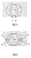
- Fig. 1 illustrates the covering and uncovering background situations.
- a moving object a circle, is shown moving (with motion vector D ) from left to right.
- N indicates the position in field n, while N+1 indicates the position in field n+1.
- Region I is uncovered in field n+1, while for region III covering occurs.
- Region II can be interpolated from both fields.
- the precision of the method is not optimally suited for the image(s) to be interpolated.
- image only part of region I is uncovered and only part of region III becomes covered.
- the fraction depends on the temporal position of the interpolated image relative to the neighboring original images. If the interpolated image has to be valid at the temporal instance exactly in between the previous and next original, than the covering and uncovering areas are half the size that we detected.
- Fig. 2 illustrates this case into more detail, and shows, particularly, regions in which covering and uncovering occurs, and where in the interpolated image which motion vector can be safely used, and from which, next or previous, image data should be used in the interpolation process.
- Region Ia can be interpolated from the next image using vector D ? .
- Region Ib can be interpolated from the next and the previous image using vector D b .
- Region IIIa can be interpolated from the next and the previous image using vector D f .
- Region IIIb can be interpolated from the next image using vector D ? .
- a practical solution for all regions will be introduced.
- ⁇ b ' and ⁇ f ' according to: and where N B1 stands for the number of samples in block B 1 ( X ). Instead of a fourth power, a second power can also be used.
- the block B 1 ( X ) is not necessarily identical to B( X ). A smaller block size will mostly be preferred, as this allows a more detailed region categorization. This error measure has been chosen since it has proven to be the most effective, in most cases.
- Th is an experimentally determined, small, threshold value. In words: we assume to be in region Ib when D b can be considered valid. This occurs when, at the temporal position of the image to be interpolated, the two luminance values obtained according to D b , i.e. the one from the delayed field and the one from the current field, can be matched with a small error. We assume to be in region Ia when D b cannot be considered valid.
- vectors D ? occur, which up to now have no meaning. They are required for those parts of the interpolated image where there is either covering or uncovering. Therefore it is known that either the previous or the next image should be solely used in the interpolation, but no valid vector is available to shift the corresponding background that either appears or disappears.
- this nearest vector is obtained from the backward predicting motion estimator, generating D b , at a location shifted over the negative value of the forward predicting motion vector D f , multiplied by ⁇ , the temporal position of the image to be interpolated.
- this nearest vector is obtained from the forward predicting motion estimator, generating D f , at a location shifted over the negative value of the backward predicting motion vector D b , multiplied by (1 ⁇ ).
- regions Ib and IIIa a safer version of the interpolation according to the current invention would use a similar approach.
- motion compensated weighted averaging is proposed for 'uncomplicated' areas.
- region Ib and IIIa i.e. the areas in which there is no actual covering in the image to be interpolated, but yet near a complicated region, the robust interpolation according to (14) is proposed.
- FIG. 3 An input video signal I is applied to a dual estimator DE having two motion vector estimators ME1, ME2.
- the input video signal I is applied to a field delay FM1, a first input of the first motion vector estimator ME1, and to a first input of the second motion vector estimator ME2 thru a shifter S2.
- An output signal of the field delay FM1 is applied to a second input of the second motion estimator ME2, and to a second input of the first motion vector estimator ME1 thru a shifter S1.
- the first motion vector estimator ME1 supplies the vector Df
- the second motion vector estimator ME2 supplies the vector Db.
- the input video signal I is also applied to a motion-compensated interpolator MCI.
- the input video signal I is applied to a field delay FM2, and to a shifter S3.
- An output of the field delay FM2 is applied to a shifter S4.
- the shifters S3, S4 are controlled by the motion vectors Db, Df received from the dual estimator DE.
- Outputs of the shifters S3, S4 are applied to a median circuit med and to an average circuit Av.
- Outputs of the median circuit med and the average circuit Av are applied to a multiplexer MUX which supplies the output signal O to a display device CRT for displaying the output signal at, for example, a 100 Hz field rate.
- the motion vectors Db, Df, their errors ⁇ b, ⁇ f, and threshold values m1, m2 are applied to a region detector RD which furnishes a control signal to the multiplexer MUX.
- a primary aspect of the invention can be summarized as follows.
- an artifact is visible at the boundary of moving objects where either covering or uncovering of backgrounds occurs. It is the object of the present invention to eliminate this local artifact.
- areas where covering and uncovering occur are recognized based on the relative prediction quality of two motion vectors.
- the two motion vectors are estimated between the same field pair, but differ in that the first is calculated to optimally predict the previous field from the next, whereas the second tries to predict the next field from the previous.
- An upconversion method using the two motion vectors is also described in this disclosure.
- two motion vectors one predicting the next image from the previous image and the other predicting the previous image from the next, are taken from both sides of a discontinuity in the vector field, and both applied to predict the next image from the previous and to predict the previous image from the next, and a choice between the vectors is made in dependence on the relative suitability for the tested prediction.
- a preferred embodiment can be summarized as follows.
- An image between neighboring images in a sequence is interpolated by applying two motion vectors V b and V f , one optimally suited for backwards predicting and the other for forwards prediction.
- the embodiment comprises:
Landscapes
- Engineering & Computer Science (AREA)
- Multimedia (AREA)
- Computer Vision & Pattern Recognition (AREA)
- Physics & Mathematics (AREA)
- General Physics & Mathematics (AREA)
- Theoretical Computer Science (AREA)
- Signal Processing (AREA)
- Television Systems (AREA)
- Picture Signal Circuits (AREA)
Claims (10)
- Verfahren zum Detektieren bedeckter und unbedeckter Teile in einem Bild (II), das zwischen benachbarten vorhergehenden (I) und nachfolgenden (III) Eingangsbilder interpoliert werden soll, wobei das Verfahren die nachfolgenden Verfahrensschritte umfasst:wobei dieses Verfahren gekennzeichnet ist durch die weiteren nachfolgenden Verfahrensschritte:das Detektieren von Bewegung von dem genannten nächsten Eingangsbild (III) zu dem genannten vorhergehenden Eingangsbild (I), was zu Rückwärts-Bewegungsvektoren (Db) mit entsprechenden Rückwärts-Schätzungsfehlern εb führt;das Detektieren von Bewegung von dem genannten vorhergehenden Eingangsbild (I) zu dem genannten nächsten Eingangsbild (III), was zu Vorwärts-Bewegungsvektoren (Df) mit entsprechenden Vorwärts-Schätzungsfehlern εf führt;das Detektieren erster unbedeckter (I) und erster bedeckter (III) Teile in dem genannten benachbarten vorhergehenden (I) und nächsten (III) Eingangsbild;das in den auf diese Weise detektierten ersten unbedeckten Teilen (I) Detektieren zweiter unbedeckter Teile (Ta) in dem genannten zu interpolierenden Bild (II), dadurch, dass zweite Rückwärts-Schätzungsfehler ermittelt werden durch einen Vergleich benachbarter vorhergehender (I) und nachfolgender (III) Eingangsbilder, wenn über die genannten Rückwärts-Bewegungsvektoren (Db) zu einer einstweiligen Lage des genannten zu implementierenden Bildes (II) verschoben, und durch Vergleich der genannten zweiten Rückwärts-Schätzungsfehler mit einer Schwelle; unddas in den genannten, auf diese Weise detektierten ersten bedeckten Teilen (III) Detektieren zweiter bedeckter Teile (IIIb) in dem genannten zu interpolierenden Bild (II) durch Ermittlung zweiter Vorwärts-Schätzungsfehler durch Vergleich benachbarter vorhergehender (I) und nachfolgender (III) Eingangsbilder, wenn über die genannten Vorwärts-Bewegungsvektoren (Df) zu einer einstweiligen Stelle des genannten zu interpolierenden Bildes (II) verschoben, und durch Vergleich der genannten zweiten Vorwärts-Schätzungsfehler mit der genannten Schwelle.
- Verfahren nach Anspruch 1, wobei der genannte Schritt der Detektion der genannten ersten unbedeckten (I) und der genannten ersten bedeckten (III) Teile in den genannten benachbarten vorhergehenden (I) und nachfolgenden (III) Eingangsbildern den Schritt umfasst der Verarbeitung der genannten Rückwärts-Schätzungsfehler (εb) und der genannten Vorwärts-Schätzungsfehler (εf) zum Detektieren der genannten ersten unbedeckten (I) und der genannten ersten bedeckten (III) Teile in dem genannten benachbarten vorhergehenden (I) und nachfolgenden (III) Eingangsbild.
- Verfahren zum Schätzen von Bewegungsvektoren, wobei dieses Verfahren die nachfolgenden Verfahrensschritte umfasst:das Detektieren bedeckter und unbedeckter Teile in einem zu interpolierenden Bild nach Anspruch 1; unddas Liefern von Bewegungsvektoren für die genannten bedeckten und unbedeckten Teilen in dem genannten zu Interpolierenden Bild (II), und zwar abhängig von den genannten Rückwärts-Bewegungsvektoren (Db) und der genannten Vorwärts-Bewegungsvektoren (Df).
- Verfahren nach Anspruch 3, wobei die genannten Bewegungsvektoren einen Verfahrensschritt liefern, der die nachfolgenden Schritte umfasst:das Liefern von Bewegungsvektoren für die genannten zweiten unbedeckten Teile (Ia) in Abhängigkeit von den genannten Vorwärts-Bewegungsvektoren (Df), genommen von den Stellen, die über die genannten Rückwärts-Bewegungsvektoren (Db) verschoben sind; unddas Liefern von Bewegungsvektoren für die genannten zweiten bedeckten Teile (IIIb) in Abhängigkeit von den genannten Rückwärts-Bewegungsvektoren (Db), genommen von den Stellen, die über die genannten Vorwärts-Bewegungsvektoren (Df) verschoben sind.
- Verfahren nach Anspruch 3, wobei die genannten Schritte der Lieferung von Bewegungsvektoren für die genannten zweiten unbedeckten (Ia) und zweiten bedeckten (IIIb) Teile die nachfolgenden Verfahrensschritte umfassen:das Liefern erster Bewegungsvektoren für die genannten zweiten unbedeckten Teile (Ia), indem die genannten Vorwärts-Bewegungsvektoren (Df) von Stellen genommen werden, die über die genannten Rückwärts-Bewegungsvektoren (Db) verschoben sind;das Liefern zweiter Bewegungsvektoren für die genannten zweiten unbedeckten Teile (Ia), indem die genannten Vorwärts-Bewegungsvektoren (Df) von Stellen genommen werden, die über die genannten Rückwärts-Bewegungsvektoren (Db) verschoben sind, entsprechend einer einstweiligen Stelle des genannten Bildes (II), das zwischen den genannten benachbarten vorhergehenden (I) und nächsten (III) Bildern interpoliert werden soll;das Liefern erster Bewegungsvektoren für die genannten zweiten bedeckten Teile (IIIb), dadurch, dass die genannten Rückwärts-Bewegungsvektoren (Db) von Stellen genommen werden, die über die genannten Vorwärts-Bewegungsvektoren (Df) verschoben sind;das Liefern zweiter Bewegungsvektoren für die genannten zweiten bedeckten Teile (IIIb), dadurch, dass die genannten Rückwärts-Bewegungsvektoren (Db) von Stellen genommen werden, die über die genannten Vorwärts-Bewegungsvektoren (Df) verschoben sind, und zwar entsprechend einer einstweiligen Stelle des genannten Bildes (II), das zwischen den genannten benachbarten vorhergehenden (I) und nachfolgenden (III) Bildern interpoliert werden soll.
- Verfahen zum Interpolieren eines Bildes (II) zwischen benachbarten vorhergehenden (I) und nachfolgenden (III) Eingangsbildern, wobei dieses Verfahren die nachfolgenden Verfahrensschritte umfasst:das Schätzen von Bewegungsvektoren für das genannte Bild (II), das entsprechend dem Anspruch 3 interpoliert werden soll, unddas Liefern der genannten zu interpolierenden Bildes (II), und zwar mit Hilfe der genannten Rückwärts-Bewegungsvektoren (Db), der genannten Vorwärts-Bewegungsvektoren (Df), der genannten Bewegungsvektoren für die genannten zweiten unbedeckten Teile (Ia), und der genannten Bewegungsvektoren für die genannten zweiten bedeckten Teile (IIIb).
- Anordnung (DE) zum Detektieren bedeckter und unbedeckter Teile in einem Bild (II), das zwischen benachbarten vorhergehenden (I) und nachfolgenden (III) Eingangsbildern interpoliert werden soll, wobei diese Anordnung die nachfolgenden Mittel umfasst:Mittel (ME2) zum Detektieren von Bewegung von dem genannten nächsten Eingangsbild (II) zu dem genannten vorhergehenden Eingangsbild (I), was zu Rückwärts-Bewegungsvektoren (Db) mit entsprechenden Rückwärts-Schätzungsfehlern (εb) führt;Mittel (ME1) zum Detektieren von Bewegung von dem genannten vorhergehenden Eingangsbild (I) zu dem genannten nachfolgenden Eingangsbild (III), was zu Vorwärts-Bewegungsvektoren (Df) mit entsprechenden Vorwärts-Schätzungsfehlern (εf) führt;Mittel zum Detektieren erster unbedeckter (I) und erster bedeckter (III) Teile in den genannten benachbarten vorhergehenden (I) und nachfolgenden (III) Eingangsbildern;Mittel (RD) zum in den genannten auf diese Weise detektierten ersten unbedeckten Teilen (I) Detektieren zweiter unbedeckter Teile (Ia) in dem genannten zu interpolierenden Bild (II), dadurch, dass zweite Rückwärts-Schätzungsfehler ermittelt werden durch Vergleich der benachbarten vorhergehenden (I) und der nachfolgenden (III) Eingangsbilder, wenn über die genannten Rückwärts-Bewegungsvektoren (Db) zu einer einstweiligen Stelle des genannten zu interpolierenden Bildes (II) verschoben, und durch Vergleich der genannten Rückwärts-Schätzungsfehler mit einer Schwelle; undMittel (RD) zum in den genannten auf diese Weise detektierten ersten bedeckten Teilen (III) Detektieren zweiter bedeckter Teile (IIIb) in dem genannten zu interpolierenden Bild (II), indem zweite Vorwärts-Schätzungsfehler ermittelt werden durch Vergleich benachbarter vorhergehender (I) und nachfolgender (III) Eingangsbilder, wenn über die genannten Vorwärts-Bewegungsvektoren (Df) zu einer einstweiligen Stelle des genannten zu interpolierenden Bildes (II) verschoben, und durch Vergleich der genannten zweiten Vorwärts-Schätzungsfehler mit der genannten Schwelle.
- Anordnung zum Schätzen von Bewegungsvektoren, wobei diese Anordnung die nachfolgenden Elemente umfasst:eine Anordnung zum Detektieren bedeckter und unbedeckter Teile in einem zu interpolierenden Bild nach Anspruch 7, undMittel zum Liefern von Bewegungsvektoren für die genannten bedeckten und unbedeckten Teile in dem zu interpolierenden Bild (II), in Abhängigkeit von den genannten Rückwärts-Bewegungsvektoren (Db) und den genannten Vorwärts-Bewegungsvektoren (Df).
- Anordnung nach Anspruch 8, wobei die genannten Bewegungsvektoren, die Mittel liefern, die folgenden Elemente umfassen:Mittel zum Liefern von Bewegungsvektoren für die genannten zweiten unbedeckten Teile (Ia) in Abhängigkeit von den genannten Vorwärts-Bewegungsvektoren (Df), genommen von Stellen, die über den genannten Rückwärts-Bewegungsvektor (Db) verschoben sind; undMittel zum Liefern von Bewegungsvektoren für die genannten zweiten bedeckten Teile (IIIb) in Abhängigkeit von den genannten Rückwärts-Bewegungsvektoren (Db), genommen von Stellen, die über den genannten Vorwärts-Bewegungsvektor (Df) verschoben sind.
- Wiedergabeanordnung, welche die nachfolgenden Elemente umfasst:eine Anordnung (DE) zum Schätzen von Bewegungsvektoren für ein Bild (II), das zwischen benachbarten vorhergehenden (I) und nachfolgenden (III) Eingangsbildern interpoliert werden soll, wie in Anspruch 9 definiert;Mittel (MCI) zum Interpolieren des genannten Bildes (II) zwischen den genannten benachbarten vorhergehenden (I) und nachfolgenden (III) Eingangsbilder mit Hilfe der genannten Rückwärts-Bewegungsvektoren (Db), der genannten Vorwärts-Bewegungsvektoren (Df), der genannten Bewegungsvektoren für die genannten unbedeckten Teile, und der genannten Bewegungsvektoren für die genannten bedeckten Teile; undMittel (CRT) zum Wiedergeben einer Bildsequenz, geformt durch die genannten benachbarten vorhergehenden (I) und nachfolgenden (III) Eingangsbilder und das genannte Bild (II).
Priority Applications (1)
| Application Number | Priority Date | Filing Date | Title |
|---|---|---|---|
| EP98945486A EP0948865B1 (de) | 1997-10-29 | 1998-10-12 | Bewegungsvektorschätzung und detektion von bedeckten/unbedeckten bildteilen |
Applications Claiming Priority (4)
| Application Number | Priority Date | Filing Date | Title |
|---|---|---|---|
| EP97202562 | 1997-10-29 | ||
| EP97202562 | 1997-10-29 | ||
| PCT/IB1998/001594 WO1999022520A2 (en) | 1997-10-29 | 1998-10-12 | Motion vector estimation and detection of covered/uncovered image parts |
| EP98945486A EP0948865B1 (de) | 1997-10-29 | 1998-10-12 | Bewegungsvektorschätzung und detektion von bedeckten/unbedeckten bildteilen |
Publications (2)
| Publication Number | Publication Date |
|---|---|
| EP0948865A1 EP0948865A1 (de) | 1999-10-13 |
| EP0948865B1 true EP0948865B1 (de) | 2003-02-26 |
Family
ID=8228653
Family Applications (1)
| Application Number | Title | Priority Date | Filing Date |
|---|---|---|---|
| EP98945486A Expired - Lifetime EP0948865B1 (de) | 1997-10-29 | 1998-10-12 | Bewegungsvektorschätzung und detektion von bedeckten/unbedeckten bildteilen |
Country Status (5)
| Country | Link |
|---|---|
| US (1) | US6219436B1 (de) |
| EP (1) | EP0948865B1 (de) |
| JP (1) | JP2001507552A (de) |
| DE (1) | DE69811631T2 (de) |
| WO (1) | WO1999022520A2 (de) |
Families Citing this family (54)
| Publication number | Priority date | Publication date | Assignee | Title |
|---|---|---|---|---|
| JP2002523985A (ja) | 1998-08-21 | 2002-07-30 | コーニンクレッカ フィリップス エレクトロニクス エヌ ヴィ | 画像信号における問題領域位置決め |
| CA2646791C (en) | 1999-12-28 | 2012-02-28 | Sony Corporation | Signal processing device and method, and recording medium |
| EP1287492A2 (de) * | 2000-05-18 | 2003-03-05 | Koninklijke Philips Electronics N.V. | Bewegungsschätzer für reduzierte halos in der bewegungskompensierten bildratenerhöhung |
| WO2001091468A1 (en) * | 2000-05-19 | 2001-11-29 | Koninklijke Philips Electronics N.V. | Method, system and apparatus |
| US6760376B1 (en) | 2000-11-06 | 2004-07-06 | Koninklijke Philips Electronics N.V. | Motion compensated upconversion for video scan rate conversion |
| ES2283376T3 (es) * | 2001-01-16 | 2007-11-01 | Koninklijke Philips Electronics N.V. | Reduccion de los efectos de tipo halo en una interpolacion compensada en movimiento. |
| US7042945B2 (en) * | 2001-04-24 | 2006-05-09 | Bellers Erwin B | 3-D recursive vector estimation for video enhancement |
| JP4596203B2 (ja) * | 2001-02-19 | 2010-12-08 | ソニー株式会社 | 画像処理装置および方法、記録媒体、並びにプログラム |
| CN1224246C (zh) * | 2001-02-21 | 2005-10-19 | 皇家菲利浦电子有限公司 | 一种选择运动矢量的方法和装置 |
| CA2419636A1 (en) * | 2001-06-15 | 2003-02-12 | Sony Corporation | Image processing apparatus and method, and image pickup apparatus |
| JP4596219B2 (ja) * | 2001-06-25 | 2010-12-08 | ソニー株式会社 | 画像処理装置および方法、記録媒体、並びにプログラム |
| JP4596224B2 (ja) | 2001-06-27 | 2010-12-08 | ソニー株式会社 | 画像処理装置および方法、記録媒体、並びにプログラム |
| ATE320143T1 (de) | 2001-11-07 | 2006-03-15 | Koninkl Philips Electronics Nv | Vorrichtung und verfahren zum erkennen von verdeckung |
| CN100358356C (zh) | 2002-02-28 | 2007-12-26 | 皇家飞利浦电子股份有限公司 | 用于场速率上变换的方法和装置 |
| US7027510B2 (en) * | 2002-03-29 | 2006-04-11 | Sony Corporation | Method of estimating backward motion vectors within a video sequence |
| JP2006513661A (ja) * | 2003-01-23 | 2006-04-20 | コーニンクレッカ フィリップス エレクトロニクス エヌ ヴィ | バックグラウンド動きベクトル検出方法及び装置 |
| JP2008521324A (ja) * | 2004-11-22 | 2008-06-19 | コーニンクレッカ フィリップス エレクトロニクス エヌ ヴィ | カバーリング及びアンカバーリングを扱う動きベクトル場の投影 |
| GB0500174D0 (en) | 2005-01-06 | 2005-02-16 | Kokaram Anil | Method for estimating motion and occlusion |
| EP1855474A1 (de) * | 2006-05-12 | 2007-11-14 | Sony Deutschland Gmbh | Verfahren zur Erzeugung eines interpolierten Bildes zwischen zwei Bildern einer Eingangsbildsequenz |
| JP4878628B2 (ja) | 2006-09-15 | 2012-02-15 | パナソニック株式会社 | 映像処理装置および映像処理方法 |
| KR100814424B1 (ko) * | 2006-10-23 | 2008-03-18 | 삼성전자주식회사 | 폐색영역 검출장치 및 검출방법 |
| US8254444B2 (en) | 2007-05-14 | 2012-08-28 | Samsung Electronics Co., Ltd. | System and method for phase adaptive occlusion detection based on motion vector field in digital video |
| US8144247B2 (en) * | 2007-06-21 | 2012-03-27 | Samsung Electronics Co., Ltd. | Detection and interpolation of still objects in a video sequence |
| US8126063B2 (en) * | 2007-06-21 | 2012-02-28 | Samsung Electronics Co., Ltd. | System and method for still object detection based on normalized cross correlation |
| US7990476B2 (en) * | 2007-09-19 | 2011-08-02 | Samsung Electronics Co., Ltd. | System and method for detecting visual occlusion based on motion vector density |
| US20090161978A1 (en) * | 2007-12-20 | 2009-06-25 | Marinko Karanovic | Halo Artifact Removal Method |
| WO2009085205A1 (en) * | 2007-12-20 | 2009-07-09 | Integrated Device Technology, Inc. | Image interpolation with halo reduction |
| JP5453304B2 (ja) * | 2007-12-20 | 2014-03-26 | クゥアルコム・インコーポレイテッド | 適応探索範囲を用いた動き推定 |
| US8213512B2 (en) * | 2008-05-28 | 2012-07-03 | Cyberlink Corp. | Determining an intermediate image |
| TW201001339A (en) * | 2008-06-25 | 2010-01-01 | Univ Nat Chiao Tung | Method of detecting moving object |
| US8259225B2 (en) * | 2008-08-20 | 2012-09-04 | Samsung Electronics Co., Ltd. | System and method for reducing visible halo in digital video with dual motion estimation |
| US8265421B2 (en) * | 2008-11-06 | 2012-09-11 | Sony Corporation | Video system with blocking artifact two-dimensional cross filtering |
| FR2938943B1 (fr) * | 2008-11-21 | 2010-11-12 | Thales Sa | Systeme multiprocesseur. |
| WO2010091937A1 (en) * | 2009-02-12 | 2010-08-19 | Zoran (France) | Temporal video interpolation method with 2-frame occlusion handling |
| WO2010091934A1 (en) | 2009-02-12 | 2010-08-19 | Zoran (France) | Video sequence analysis for robust motion estimation |
| EP2227012A1 (de) | 2009-03-05 | 2010-09-08 | Sony Corporation | Verfahren und System zum Bereitstellen zuverlässiger Bewegungsvektoren |
| ES2586333T3 (es) | 2009-03-30 | 2016-10-13 | Vestel Elektronik Sanayi Ve Ticaret A.S. | Estimación de movimiento de fondo basada en reducción del halo |
| EP2237560A1 (de) | 2009-03-30 | 2010-10-06 | Vestel Elektronik Sanayi ve Ticaret A.S. | Interpolation à compensation de mouvement de réduction de halo |
| TWI408621B (zh) * | 2009-11-17 | 2013-09-11 | Mstar Semiconductor Inc | 影像插補處理裝置及其方法 |
| US8233085B1 (en) | 2009-12-08 | 2012-07-31 | Kolorific, Inc. | Method and system for interpolating a pixel value of a pixel located at an on-screen display |
| US8537283B2 (en) | 2010-04-15 | 2013-09-17 | Qualcomm Incorporated | High definition frame rate conversion |
| ES2660610T3 (es) | 2010-04-30 | 2018-03-23 | Vestel Elektronik Sanayi Ve Ticaret A.S. | Procedimiento y aparato para la detección y clasificación de regiones de oclusión |
| JP2012089986A (ja) | 2010-10-18 | 2012-05-10 | Mitsubishi Electric Corp | 画像処理装置及び方法、並びに画像表示装置及び方法 |
| JP5863273B2 (ja) * | 2011-05-02 | 2016-02-16 | キヤノン株式会社 | 画像処理装置、制御方法及びプログラム |
| CN102542575B (zh) * | 2011-12-06 | 2014-09-10 | 晶门科技(深圳)有限公司 | 基于运动向量投影的静止物体和运动背景区域的检测方法及装置 |
| US9148622B2 (en) * | 2011-12-29 | 2015-09-29 | Hong Kong Applied Science and Technology Research Institute Company, Limited | Halo reduction in frame-rate-conversion using hybrid bi-directional motion vectors for occlusion/disocclusion detection |
| KR101908388B1 (ko) * | 2012-07-19 | 2018-10-17 | 삼성전자 주식회사 | 폐색 영역 복원 장치, 폐색 영역을 복원하는 비디오 디코딩 장치 및 폐색 영역 복원 방법 |
| KR101394468B1 (ko) | 2013-11-12 | 2014-05-14 | 주식회사 아나패스 | 블록의 불연속도 연산방법 및 이를 이용한 폴백 수행 방법 |
| US10554965B2 (en) | 2014-08-18 | 2020-02-04 | Google Llc | Motion-compensated partitioning |
| JP6412819B2 (ja) * | 2015-03-30 | 2018-10-24 | 株式会社東芝 | 画像処理装置、画像処理方法、および画像処理プログラム |
| US10397600B1 (en) | 2016-01-29 | 2019-08-27 | Google Llc | Dynamic reference motion vector coding mode |
| US10462457B2 (en) | 2016-01-29 | 2019-10-29 | Google Llc | Dynamic reference motion vector coding mode |
| JP7057079B2 (ja) * | 2017-09-01 | 2022-04-19 | キヤノン株式会社 | 画像処理装置、撮像装置、画像処理方法、及びプログラム |
| CN116156085A (zh) * | 2021-11-23 | 2023-05-23 | 瑞昱半导体股份有限公司 | 图像处理方法与图像处理电路 |
Family Cites Families (11)
| Publication number | Priority date | Publication date | Assignee | Title |
|---|---|---|---|---|
| FR535066A (fr) * | 1921-05-04 | 1922-04-08 | Système de dossier de chaise élastique et réglable particulièrement destiné aux chaises de dactylographes | |
| GB9013642D0 (en) | 1990-06-19 | 1990-08-08 | British Broadcasting Corp | Video signal processing |
| GB2265783B (en) * | 1992-04-01 | 1996-05-29 | Kenneth Stanley Jones | Bandwidth reduction employing a classification channel |
| FR2700090B1 (fr) * | 1992-12-30 | 1995-01-27 | Thomson Csf | Procédé de désentrelacement de trames d'une séquence d'images animées. |
| GB2279531B (en) * | 1993-06-24 | 1997-07-16 | Sony Uk Ltd | Motion compensated image interpolation |
| DE69602818T2 (de) | 1995-03-14 | 1999-12-16 | Koninklijke Philips Electronics N.V., Eindhoven | Bewegungskompensierte interpolation |
| KR0181034B1 (ko) * | 1995-03-18 | 1999-05-01 | 배순훈 | 특징점 기반 움직임 추정을 이용한 움직임 벡터 검출 방법 및 장치 |
| DE19525531A1 (de) * | 1995-07-13 | 1997-01-16 | Philips Patentverwaltung | Verfahren zur Zwischenbild-Interpolation von Farbdifferenzsignalen sowie Schaltungsanordnung zur Durchführung dieses Verfahrens |
| EP0778698B1 (de) * | 1995-12-06 | 2001-09-12 | THOMSON multimedia | Verfahren und Vorrichtung zur Feinbestimmung eines Bewegungsvektors für digitale Videobilder |
| US5995080A (en) * | 1996-06-21 | 1999-11-30 | Digital Equipment Corporation | Method and apparatus for interleaving and de-interleaving YUV pixel data |
| US6026217A (en) * | 1996-06-21 | 2000-02-15 | Digital Equipment Corporation | Method and apparatus for eliminating the transpose buffer during a decomposed forward or inverse 2-dimensional discrete cosine transform through operand decomposition storage and retrieval |
-
1998
- 1998-10-12 JP JP52357099A patent/JP2001507552A/ja active Pending
- 1998-10-12 WO PCT/IB1998/001594 patent/WO1999022520A2/en not_active Ceased
- 1998-10-12 EP EP98945486A patent/EP0948865B1/de not_active Expired - Lifetime
- 1998-10-12 DE DE69811631T patent/DE69811631T2/de not_active Expired - Fee Related
- 1998-10-28 US US09/181,160 patent/US6219436B1/en not_active Expired - Fee Related
Also Published As
| Publication number | Publication date |
|---|---|
| DE69811631D1 (de) | 2003-04-03 |
| US6219436B1 (en) | 2001-04-17 |
| EP0948865A1 (de) | 1999-10-13 |
| WO1999022520A2 (en) | 1999-05-06 |
| JP2001507552A (ja) | 2001-06-05 |
| DE69811631T2 (de) | 2003-10-30 |
| WO1999022520A3 (en) | 1999-08-05 |
Similar Documents
| Publication | Publication Date | Title |
|---|---|---|
| US6219436B1 (en) | Motion vector estimation and detection of covered/uncovered image parts | |
| US7010039B2 (en) | Motion estimator for reduced halos in MC up-conversion | |
| US6487313B1 (en) | Problem area location in an image signal | |
| CN100438609C (zh) | 带有降质的图像处理单元 | |
| US5502492A (en) | Motion vector detection apparatus | |
| WO2003024116A1 (en) | Motion estimation and/or compensation | |
| JP2004518341A (ja) | 単一のテレビジョン信号フィールド中で並行して生ずるフィルム及びビデオオブジェクトの認識 | |
| US20050180506A1 (en) | Unit for and method of estimating a current motion vector | |
| GB2435360A (en) | Determining motion between video images | |
| EP1444837B1 (de) | Vorrichtung und verfahren zum erkennen von verdeckung | |
| KR20040050906A (ko) | 모션 추정을 위한 장치 및 방법 | |
| US20050163355A1 (en) | Method and unit for estimating a motion vector of a group of pixels | |
| US20080144716A1 (en) | Method For Motion Vector Determination | |
| US8102915B2 (en) | Motion vector fields refinement to track small fast moving objects | |
| WO2004082294A1 (en) | Method for motion vector determination | |
| JPH08223540A (ja) | 動きベクトルを用いた動き内挿方法および動き内挿回路ならびに動きベクトル検出方法および動きベクトル検出回路 | |
| Mertens et al. | Motion vector field improvement for picture rate conversion with reduced halo | |
| Zhang et al. | Improved measures for motion-compensated frame rate conversion | |
| WO2000072590A2 (en) | Block matching | |
| Chen et al. | A logarithmic-time adaptive block-matching algorithm for estimating large-displacement motion vectors |
Legal Events
| Date | Code | Title | Description |
|---|---|---|---|
| PUAI | Public reference made under article 153(3) epc to a published international application that has entered the european phase |
Free format text: ORIGINAL CODE: 0009012 |
|
| 17P | Request for examination filed |
Effective date: 19990729 |
|
| AK | Designated contracting states |
Kind code of ref document: A1 Designated state(s): DE ES FR GB IT |
|
| 17Q | First examination report despatched |
Effective date: 20000802 |
|
| GRAG | Despatch of communication of intention to grant |
Free format text: ORIGINAL CODE: EPIDOS AGRA |
|
| GRAG | Despatch of communication of intention to grant |
Free format text: ORIGINAL CODE: EPIDOS AGRA |
|
| GRAH | Despatch of communication of intention to grant a patent |
Free format text: ORIGINAL CODE: EPIDOS IGRA |
|
| GRAH | Despatch of communication of intention to grant a patent |
Free format text: ORIGINAL CODE: EPIDOS IGRA |
|
| GRAA | (expected) grant |
Free format text: ORIGINAL CODE: 0009210 |
|
| AK | Designated contracting states |
Designated state(s): DE ES FR GB IT |
|
| PG25 | Lapsed in a contracting state [announced via postgrant information from national office to epo] |
Ref country code: IT Free format text: LAPSE BECAUSE OF FAILURE TO SUBMIT A TRANSLATION OF THE DESCRIPTION OR TO PAY THE FEE WITHIN THE PRESCRIBED TIME-LIMIT;WARNING: LAPSES OF ITALIAN PATENTS WITH EFFECTIVE DATE BEFORE 2007 MAY HAVE OCCURRED AT ANY TIME BEFORE 2007. THE CORRECT EFFECTIVE DATE MAY BE DIFFERENT FROM THE ONE RECORDED. Effective date: 20030226 |
|
| REG | Reference to a national code |
Ref country code: GB Ref legal event code: FG4D |
|
| REG | Reference to a national code |
Ref country code: GB Ref legal event code: 746 Effective date: 20030304 |
|
| REF | Corresponds to: |
Ref document number: 69811631 Country of ref document: DE Date of ref document: 20030403 Kind code of ref document: P |
|
| ET | Fr: translation filed | ||
| PG25 | Lapsed in a contracting state [announced via postgrant information from national office to epo] |
Ref country code: ES Free format text: LAPSE BECAUSE OF FAILURE TO SUBMIT A TRANSLATION OF THE DESCRIPTION OR TO PAY THE FEE WITHIN THE PRESCRIBED TIME-LIMIT Effective date: 20030828 |
|
| REG | Reference to a national code |
Ref country code: FR Ref legal event code: D6 |
|
| PGFP | Annual fee paid to national office [announced via postgrant information from national office to epo] |
Ref country code: FR Payment date: 20031027 Year of fee payment: 6 |
|
| PGFP | Annual fee paid to national office [announced via postgrant information from national office to epo] |
Ref country code: GB Payment date: 20031031 Year of fee payment: 6 |
|
| PGFP | Annual fee paid to national office [announced via postgrant information from national office to epo] |
Ref country code: DE Payment date: 20031215 Year of fee payment: 6 |
|
| PLBE | No opposition filed within time limit |
Free format text: ORIGINAL CODE: 0009261 |
|
| STAA | Information on the status of an ep patent application or granted ep patent |
Free format text: STATUS: NO OPPOSITION FILED WITHIN TIME LIMIT |
|
| 26N | No opposition filed |
Effective date: 20031127 |
|
| PG25 | Lapsed in a contracting state [announced via postgrant information from national office to epo] |
Ref country code: GB Free format text: LAPSE BECAUSE OF NON-PAYMENT OF DUE FEES Effective date: 20041012 |
|
| PG25 | Lapsed in a contracting state [announced via postgrant information from national office to epo] |
Ref country code: DE Free format text: LAPSE BECAUSE OF NON-PAYMENT OF DUE FEES Effective date: 20050503 |
|
| GBPC | Gb: european patent ceased through non-payment of renewal fee |
Effective date: 20041012 |
|
| PG25 | Lapsed in a contracting state [announced via postgrant information from national office to epo] |
Ref country code: FR Free format text: LAPSE BECAUSE OF NON-PAYMENT OF DUE FEES Effective date: 20050630 |
|
| REG | Reference to a national code |
Ref country code: FR Ref legal event code: ST |