EP0948224B1 - Verfahren zur drahtlosen Datenübertragung und Zwischenstation - Google Patents
Verfahren zur drahtlosen Datenübertragung und Zwischenstation Download PDFInfo
- Publication number
- EP0948224B1 EP0948224B1 EP98114704A EP98114704A EP0948224B1 EP 0948224 B1 EP0948224 B1 EP 0948224B1 EP 98114704 A EP98114704 A EP 98114704A EP 98114704 A EP98114704 A EP 98114704A EP 0948224 B1 EP0948224 B1 EP 0948224B1
- Authority
- EP
- European Patent Office
- Prior art keywords
- radio
- base station
- data
- terminal
- relay station
- Prior art date
- Legal status (The legal status is an assumption and is not a legal conclusion. Google has not performed a legal analysis and makes no representation as to the accuracy of the status listed.)
- Revoked
Links
Images

Classifications
-
- H—ELECTRICITY
- H04—ELECTRIC COMMUNICATION TECHNIQUE
- H04W—WIRELESS COMMUNICATION NETWORKS
- H04W88/00—Devices specially adapted for wireless communication networks, e.g. terminals, base stations or access point devices
- H04W88/02—Terminal devices
Definitions
- the invention is based on a method for wireless data transmission between a terminal and a base station according to the preamble of the independent claim 1 and of an intermediate station according to the preamble of the independent claim 6.
- DECT Digital Enhanced Cordless Telecommunications
- RP8001 Digital Enhanced Cordless Telecommunications
- DECT Digital Enhanced Cordless Telecommunications
- a cordless telephone designed as a DECT handset can establish a connection to the DECT repeater outside of the radio cell, that is to say if it is too far away from the base station spanning the radio cell.
- the DECT repeater establishes a connection to the base station and routes the data between the DECT-handset and the Base station remains transparent.
- the DECT repeater thus acts in the direction of the DECT handset as a base station and in the direction of the base station as a DECT handset.
- the optically coupled devices in this way each comprise an infrared interface, for example, according to the IrDA standard (Infrared Data Association).
- IrDA interfaces are already built into portable personal computers, PDA's (personal digital assistants), printers and so on.
- the EP-A 585 030 shows a procedure according to which a handset is connected to a mobile unit, which in turn can establish a radio connection to a telecommunications network.
- a PC is connected via a wireless interface to a mobile device, which in turn can transmit data in a telecommunications network.
- the inventive method with the features of independent claim 1 and the intermediate station with the features of independent claim 6 have the advantage that data between the terminal and arranged in a radio cell of the base station intermediate station are transmitted by optical signals and that the data between the Intermediate station and the base station by radio signals, preferably transmitted to the DECT standard.
- terminals with an optical transmitting and / or receiving unit can communicate with the base station designed for radio communication.
- a transition from terminals with optical interface in a radio system is made possible by means of the intermediate station in a simple manner.
- a radio channel to the base station is switched.
- the terminal is connected to the optical interface in a particularly simple manner to the radio communication system, a conventional radio channel can be set up for this connection. Therefore, no special access points may need to be connected by suitable cabling to the base station that organize an optical data exchange with the corresponding terminal. Rather, it is possible to fall back on the existing infrastructure of the radio system for the integration of the terminal with optical interface, which saves effort and costs.
- the cordless telephony system can thus be coupled to both local and public networks, so that the terminal with optical interface access to remote, connected to the data or telecommunications network computer is possible. Since access is via the radio system, no separate interface of the optical transmission system to the local or public network is required.
- a further advantage is that the intermediate station radiates radio signals derived from radio signals received by a second terminal to the base station.
- the functionality of the intermediate station is greatly expanded by the intermediate station both as a repeater for located outside the radio cell spanned by the base station or radios Cordless phones acts, as well as the transition of terminals with optical interface in the radio system allows.
- the repeater function for trained as radios or cordless telephones and the transition of terminals with optical interface in the radio system in a single intermediate station effort and cost savings, so that no separate intermediate station required for the transition of the terminals with optical interface in the radio system is.
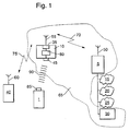
- FIG. 1 shows a block diagram of a radio system to which a terminal is connected with optical interface
- Figure 2 is a flowchart for the operation of the method according to the invention.
- 5 denotes a base station of, for example, a cordless telephone system.
- the cordless telephone system can be based, for example, the DECT standard.
- the radio system can also be a mobile radio system, for example, according to the GSM standard.
- a first transmitting / receiving antenna 50 is connected to the base station 5.
- the base station 5 spans a radio cell 65.
- a printer 30 may be connected, which is according to Figure 1 within the radio cell 65, but could also be located outside the radio cell 65.
- the printer 30 can be connected to the base station 5 at least a data or telecommunications network 15, 20, be connected 25th It can be a local or act a public network.
- the base station 5 is connected to an ISDN network 15 (Integrated Services Data Network), a local area network 20 and a trained as Internet data network 25.
- ISDN network 15 Integrated Services Data Network
- These subscribers can be arranged far outside the radio cell 65.
- an intermediate station 10 is arranged within the radio cell 65, but preferably in an edge region of the radio cell 65.
- the intermediate station 10 comprises a radio transmitting / receiving unit 35, to which a second transmitting / receiving antenna 55 is connected.
- a first radio connection 70 can thus be set up which, depending on the use of the underlying radio standard, can be a DECT radio connection, a GSM radio connection or the like.
- the DECT standard is used, so that the first radio link 70 is a DECT radio link.
- a second terminal 40 which may be formed as cordless phone, as a mobile phone, as a mobile device as a handheld radio, as a work radio or the like.
- the second terminal 40 should be designed as a cordless telephone according to the DECT standard.
- a third transmitting / receiving antenna 60 is connected to the second terminal 40.
- a second radio link 75 can be constructed, which is based on the DECT standard according to the described embodiment.
- the intermediate station 10 thus operates as a relay station in the described radio system and thereby increases the range of the base station 5.
- the second terminal 40 Since the second terminal 40 is outside the radio cell 65, it can not record a direct radio connection with the base station 5. However, it may be the second Establish radio connection 75 to the intermediate station 10.
- the intermediate station 10 sets up the first radio connection 70 to the base station 5 and forwards corresponding radio data signals between the second terminal 40 and the base station 5 in a transparent manner.
- the intermediate station 10 operates towards the second terminal 40 as a base station and towards the base station 5 as a terminal.
- a radio connection can be established in a corresponding manner by the base station 5 via the intermediate station 10 to the second terminal 40.
- the intermediate station 10 further comprises an interface 45 designed as an optical transmitter / receiver unit.
- the interface 45 can be designed, for example, to emit and receive optical signals in an infrared frequency range.
- the interface 45 may be designed, for example, according to the IrDA standard (Infrared Data Association).
- the radio transmission / reception unit 35 is connected to the interface 45.
- a first terminal 1 is arranged outside the radio cell 65.
- the first terminal 1 can also be arranged within the radio cell 65.
- the first terminal 1 comprises an optical transmitting / receiving unit 85.
- the optical transmitting / receiving unit 85 of the first terminal 1 can also emit and receive optical signals, for example in an infrared wavelength range.
- an optical connection 90 for optical data transmission can be established in this way.
- the conversion unit 80 By means of the conversion unit 80, a conversion between optical data signals and radio data signals can take place so that the first terminal 1 can also communicate with the base station 5.
- both between the first terminal 1 and a subscriber of one of the data or telecommunications networks 15, 20, 25 and the printer 30 and between the second terminal 40 and a subscriber of the data or telecommunications network 15, 20, 25 and the printer 30 data are exchanged.
- data can be transmitted from the first terminal 1 or from the second terminal 40 via the intermediate station 10 to the base station 5 and from there forwarded to a subscriber of one of the data or telecommunication networks 15, 20, 25 or the printer 30.
- any data output unit may be connected to the base station 5 and communicate in a corresponding manner with the first terminal 1 or the second terminal 40.
- a local database server, a domotic system, etc. may be connected to the base station 5 and communicate via the base station 5 and the intermediate station 10 with the first terminal 1 and / or the second terminal 40 in the manner described.
- a radio channel to the base station 5 is switched by the intermediate station 10, via which the data is transmitted from the first terminal 1 or from the second terminal 40 to the base station 5.
- the base station 5 can switch a radio channel to the intermediate station 10, via the data of a subscriber of one of the data or telecommunications networks 15, 20, 25 or other devices connected to the base station 5 to the intermediate station 10 for forwarding to the first terminal 1 and / or the second terminal 40 are transmitted.
- FIG. 2 shows a flowchart for an exemplary mode of operation of the method according to the invention.
- the intermediate station 10 checks whether there is a connection request from the first terminal 1. If this is the case, the process branches to a program point 105, otherwise it branches to a program point 125th A connection request originating from the first terminal 1 is communicated by the optical request signal of the intermediate station 10 emitted by the transmitting / receiving unit 85 of the first terminal 1, in the described embodiment in the infrared frequency range.
- the intermediate station 10 switches a radio channel to the base station 5.
- a waiting loop is traversed. Subsequently, branch back to program point 100.
- a branch is made to a program point 110.
- the intermediate station 10 checks whether optical data signals are received by the first terminal 1 in the interface 45. If this is the case, then the program branches to a point 115, otherwise it branches to a program point 130th
- converting unit 80 converts the optical data signals into radio data signals and causes the radio transmitting / receiving unit 35 to transmit the radio data signals to the base station 5.
- a program point 120 is branched.
- the intermediate station 10 checks whether the connection has been terminated. If this is the case, the program part is left, otherwise it is branched back to program point 110.
- the intermediate station 10 checks whether radio data signals have been received by the base station 5 in the radio transmission / reception unit 35 and whether these radio data signals are addressed to the first terminal 1. If this is the case, the program branches to a program point 135, otherwise the program branches to program point 120.
- the conversion unit 80 converts the radio data signals into optical data signals.
- the optical data signals are then emitted from the interface 45 to the first terminal 1 by means of the optical connection 90 in the form of an infrared connection in this exemplary embodiment. Subsequently, the program branches to point 120th
- a bidirectional optical data transmission between the intermediate station 10 and the first terminal 1 may also be provided unidirectional data transmission, depending on the direction of transmission then at the first terminal 1 only an optical transmitting device or only an optical receiving device is provided and the interface 45 only an optical Receiving device or an optical transmitting device must include. Accordingly, it is then to be provided at the intermediate station 10, only one radio unit and a radio receiver unit. In this case, however, between the second terminal 40 and the base station 5 is no data exchange is possible.
- the intermediate station 10 can in the typical applications of radio repeaters, such as DECT repeaters for large office space, factory buildings or the like in addition to the relay function for corresponding radios, such as DECT cordless telephones, a transition of terminals with optical interface in the corresponding radio system can be realized.
- radio repeaters such as DECT repeaters for large office space, factory buildings or the like
- relay function for corresponding radios such as DECT cordless telephones
Description
- Die Erfindung geht von einem Verfahren zur drahtlosen Datenübertragung zwischen einem Endgerät und einer Basisstation nach der Gattung des unabhängigen Anspruchs 1 und von einer Zwischenstation nach der Gattung des unabhängigen Anspruchs 6 aus.
- Verfahren zur drahtlosen Datenübertragung zwischen einem Endgerät und einer Basisstation sind bereits bekannt und werden für die Schnurlostelefonie angewendet. Von der Firma Dancall wird außerdem bereits der DECT-Repeater "RP8001" angeboten (DECT = Digital Enhanced Cordless Telecommunications), der als Relais-Station in einem als DECT-System ausgebildeten Schnurlostelefoniesystem arbeitet und eine vorhandene Funkzelle vergrößert. Ein solcher DECT-Repeater ist in der Regel am Rand einer Funkzelle plaziert. Ein als DECT-Mobilteil ausgebildetes Schnurlostelefon kann außerhalb der Funkzelle, das heißt bei zu großer Entfernung von der die Funkzelle aufspannenden Basisstation eine Verbindung zu dem DECT-Repeater aufbauen. Der DECT-Repeater baut daraufhin eine Verbindung zur Basisstation auf und leitet die Daten zwischen dem DECT-Mobilteil und der Basisstation transparent weiter. Der DECT-Repeater agiert somit in Richtung des DECT-Mobilteils wie eine Basisstation und in Richtung der Basisstation wie ein DECT-Mobilteil.
- Aus der Funkschau 19/95 ist es bekannt, Daten zwischen Computern und Druckern oder Telefonen drahtlos in einem Infrarotfrequenzbereich zu übertragen, wobei die auf diese Weise optisch miteinander gekoppelten Geräte jeweils eine Infrarotschnittstelle beispielsweise nach dem IrDA-Standard (Infrared Data Association) umfassen. Solche IrDA-Schnittstellen sind bereits in portable Personalcomputer, PDA's (Personal Digital Assistants), Drucker usw. eingebaut.
- Die
EP-A 585 030 - Entsprechend gilt für die
EP-A 748 139 - Das erfindungsgemäße Verfahren mit den Merkmalen des unabhängigen Anspruchs 1 und die Zwischenstation mit den Merkmalen des unabhängigen Anspruchs 6 haben demgegenüber den Vorteil, daß Daten zwischen dem Endgerät und einer in einer Funkzelle der Basisstation angeordneten Zwischenstation durch optische Signale übertragen werden und daß die Daten zwischen der Zwischenstation und der Basisstation durch Funksignale, vorzugsweise nach dem DECT-Standard übertragen werden. Auf diese Weise können Endgeräte mit einer optischen Sende- und/oder Empfangseinheit mit der für Funkverkehr ausgebildeten Basisstation kommunizieren. Somit wird mittels der Zwischenstation auf einfache Weise ein Übergang von Endgeräten mit optischer Schnittstelle in ein Funksystem ermöglicht.
- Durch die in den Unteransprüchen aufgeführten Maßnahmen sind vorteilhafte Weiterbildungen und Verbesserungen des im unabhängigen Anspruch 1 angegebenen Verfahrens und der im unabhängigen Anspruch 6 angegebenen Zwischenstation möglich.
- Besonders vorteilhaft ist es, daß bei einer Verbindungsanforderung des Endgerätes von der Zwischenstation ein Funkkanal zur Basisstation geschaltet wird. Somit wird das Endgerät mit der optischen Schnittstelle auf besonders einfache Weise an das Funkkommunikationssystem angeschlossen, wobei für diesen Anschluß ein herkömmlicher Funkkanal eingerichtet werden kann. An die Basisstation müssen daher keine speziellen Zugangspunkte möglicherweise noch durch geeignete Verkabelungen angeschlossen werden, die einen optischen Datenaustausch mit dem entsprechenden Endgerät organisieren. Vielmehr kann auf die bestehende Infrastruktur des Funksystems zur Integration des Endgerätes mit optischer Schnittstelle zurückgegriffen werden, wodurch Aufwand und Kosten eingespart werden.
- Ein weiterer Vorteil besteht darin, daß die von der Basisstation empfangenen Daten an ein angeschlossenes Daten- oder Telekommunikationsnetz übertragen werden. Das Schnurlostelefonie-System kann somit sowohl an lokalen als auch öffentlichen Netzen angekoppelt sein, so daß von dem Endgerät mit optischer Schnittstelle ein Zugriff auf entfernte, an dem Daten- oder Telekommunikationsnetz angeschlossene Rechner möglich ist. Da der Zugriff über das Funksystem erfolgt, ist keine eigene Schnittstelle des optischen Übertragungssystems zum lokalen oder öffentlichen Netz erforderlich.
- Ein weiterer Vorteil besteht darin, daß die Zwischenstation von von einem zweiten Endgerät empfangenen Funksignalen abgeleitete Funksignale an die Basisstation abstrahlt. Auf diese Weise wird die Funktionalität der Zwischenstation erheblich erweitert, indem die Zwischenstation sowohl als Repeater für außerhalb der durch die Basisstation aufgespannten Funkzelle befindliche Funkgeräte oder Schnurlostelefone wirkt, als auch den Übergang von Endgeräten mit optischer Schnittstelle in das Funksystem ermöglicht. Durch die Integration der Repeaterfunktion für als Funkgeräte oder Schnurlostelefone ausgebildete Endgeräte und des Übergangs von Endgeräten mit optischer Schnittstelle in das Funksystem in eine einzige Zwischenstation werden Aufwand und Kosten eingespart, so daß für den Übergang der Endgeräte mit optischer Schnittstelle in das Funksystem keine eigene Zwischenstation erforderlich ist.
- Ein Ausführungsbeispiel der Erfindung ist in der Zeichnung dargestellt und in der nachfolgenden Beschreibung näher erläutert. Es zeigen Figur 1 ein Blockschaltbild eines Funksystems, an das ein Endgerät mit optischer Schnittstelle angeschlossen ist, und Figur 2 einen Ablaufplan für die Funktionsweise des erfindungsgemäßen Verfahrens.
- In Figur 1 kennzeichnet 5 eine Basisstation beispielsweise eines Schnurlostelefonsystems. Dem Schnurlostelefonsystem kann dabei beispielsweise der DECT-Standard zugrundegelegt sein. Es kann sich bei dem Funksystem jedoch auch um ein Mobilfunksystem beispielsweise nach dem GSM-Standard handeln. An die Basisstation 5 ist eine erste Sende-/Empfangsantenne 50 angeschlossen. Die Basisstation 5 spannt eine Funkzelle 65 auf. An die Basisstation 5 kann ein Drucker 30 angeschlossen sein, der sich gemäß Figur 1 innerhalb der Funkzelle 65 befindet, sich jedoch auch außerhalb der Funkzelle 65 befinden könnte. Alternativ oder zusätzlich zum Drucker 30 kann an die Basisstation 5 mindestens ein Daten- oder Telekommunikationsnetz 15, 20, 25 angeschlossen sein. Dabei kann es sich um ein lokales oder ein öffentliches Netz handeln. Gemäß dem Ausführungsbeispiel nach Figur 1 ist die Basisstation 5 an ein ISDN-Netz 15 (Integrated Services Data Network), ein lokales Netz 20 und ein als Internet ausgebildetes Datennetz 25 angeschlossen. Auf diese Weise kann die Basisstation 5 mit Teilnehmern dieser Daten- oder Telekommunikationsnetze 15, 20, 25 kommunizieren. Diese Teilnehmer können weit außerhalb der Funkzelle 65 angeordnet sein. Innerhalb der Funkzelle 65, jedoch vorzugsweise in einem Randbereich der Funkzelle 65 ist eine Zwischenstation 10 angeordnet. Die Zwischenstation 10 umfaßt eine Funksende-/-empfangseinheit 35, an die eine zweite Sende-/Empfangsantenne 55 angeschlossen ist. Zwischen der Zwischenstation 10 und der Basisstation 5 kann somit eine erste Funkverbindung 70 aufgebaut werden, die je nach Verwendung des zugrundeliegenden Funkstandards eine DECT-Funkverbindung, eine GSM-Funkverbindung oder dergleichen sein kann. Im beschriebenen Ausführungsbeispiel ist der DECT-Standard zugrundegelegt, so daß die erste Funkverbindung 70 eine DECT-Funkverbindung darstellt. Außerhalb der Funkzelle 60 befindet sich ein zweites Endgerät 40, das als Schnurlostelefon, als Mobiltelefon, als Mobilfunkgerät als Handfunkgerät, als Betriebsfunkgerät oder dergleichen ausgebildet sein kann. Im vorliegenden Beispiel soll das zweite Endgerät 40 als Schnurlostelefon nach dem DECT-Standard ausgebildet sein. An das zweite Endgerät 40 ist eine dritte Sende-/Empfangsantenne 60 angeschlossen. Zwischen dem zweiten Endgerät 40 und der Zwischenstation 10 kann eine zweite Funkverbindung 75 aufgebaut werden, der gemäß dem beschriebenen Ausführungsbeispiel der DECT-Standard zugrundeliegt. Die Zwischenstation 10 arbeitet somit als Relais-Station in dem beschriebenen Funksystem und vergrößert dadurch die Reichweite der Basisstation 5. Da sich das zweite Endgerät 40 außerhalb der Funkzelle 65 befindet, kann es keine direkte Funkverbindung mit der Basisstation 5 aufnehmen. Es kann jedoch die zweite Funkverbindung 75 zur Zwischenstation 10 aufbauen. Die Zwischenstation 10 baut daraufhin die erste Funkverbindung 70 zur Basisstation 5 auf und leitet entsprechende Funkdatensignale zwischen dem zweiten Endgerät 40 und der Basisstation 5 transparent weiter. Die Zwischenstation 10 agiert in Richtung des zweiten Endgerätes 40 wie eine Basisstation und in Richtung der Basisstation 5 wie ein Endgerät. Umgekehrt kann in entsprechender Weise von der Basisstation 5 eine Funkverbindung über die Zwischenstation 10 zum zweiten Endgerät 40 aufgebaut werden.
- Die Zwischenstation 10 umfaßt weiterhin eine als optische Sende-/Empfangseinheit ausgebildete Schnittstelle 45. Die Schnittstelle 45 kann dabei beispielsweise zum Aussenden und Empfangen von optischen Signalen in einem Infrarotfrequenzbereich ausgebildet sein. Dazu kann die Schnittstelle 45 beispielsweise nach dem IrDA-Standard (Infrared Data Association) ausgebildet sein. Über eine Umsetzeinheit 80 ist die Funksende-/-empfangseinheit 35 mit der Schnittstelle 45 verbunden. Gemäß dem Ausführungsbeispiel nach Figur 1 ist außerhalb der Funkzelle 65 ein erstes Endgerät 1 angeordnet. Das erste Endgerät 1 kann jedoch auch innerhalb der Funkzelle 65 angeordnet sein. Das erste Endgerät 1 umfaßt eine optische Sende-/Empfangseinheit 85. Die optische Sende-/Empfangseinheit 85 des ersten Endgerätes 1 kann dabei ebenfalls optische Signale beispielsweise in einem Infrarotwellenlängenbereich aussenden und empfangen. Sie kann beispielsweise ebenfalls gemäß dem IrDA-Standard ausgebildet sein. Zwischen dem ersten Endgerät 1 und der Zwischenstation 10 kann auf diese Weise eine optische Verbindung 90 für eine optische Datenübertragung aufgebaut werden. Mittels der Umsetzeinheit 80 kann eine Umwandlung zwischen optischen Datensignalen und Funkdatensignalen erfolgen, so daß das erste Endgerät 1 ebenfalls mit der Basisstation 5 kommunizieren kann. Auf diese Weise können sowohl zwischen dem ersten Endgerät 1 und einem Teilnehmer eines der Daten- oder Telekommunikationsnetze 15, 20, 25 bzw. dem Drucker 30 als auch zwischen dem zweiten Endgerät 40 und einem Teilnehmer eines der Daten- oder Telekommunikationsnetzes 15, 20, 25 bzw. dem Drucker 30 Daten ausgetauscht werden. So können beispielsweise vom ersten Endgerät 1 oder vom zweiten Endgerät 40 Daten über die Zwischenstation 10 an die Basisstation 5 übertragen und von dort an einen Teilnehmer eines der Daten- oder Telekommunikationsnetze 15, 20, 25 oder den Drucker 30 weitergeleitet werden. Zusätzlich oder anstelle des Druckers 30 kann an die Basisstation 5 eine beliebige Datenausgabeeinheit angeschlossen sein und in entsprechender Weise mit dem ersten Endgerät 1 oder dem zweiten Endgerät 40 kommunizieren. Ebenso können an die Basisstation 5 ein lokaler Datenbank-Server, ein Domotik-System usw. angeschlossen sein und über die Basisstation 5 und die Zwischenstation 10 mit dem ersten Endgerät 1 und/oder dem zweiten Endgerät 40 in der beschriebenen Weise kommunizieren.
- Bei einer Verbindungsanforderung vom ersten Endgerät 1 bzw. vom zweiten Endgerät 40 wird von der Zwischenstation 10 ein Funkkanal zur Basisstation 5 geschaltet, über den die Daten vom ersten Endgerät 1 bzw. vom zweiten Endgerät 40 zur Basisstation 5 übertragen werden. Entsprechend kann umgekehrt von der Basisstation 5 ein Funkkanal zur Zwischenstation 10 geschaltet werden, über den Daten eines Teilnehmers eines der Daten- oder Telekommunikationsnetze 15, 20, 25 oder weiterer an die Basisstation 5 angeschlossener Einrichtungen an die Zwischenstation 10 zur Weiterleitung an das erste Endgerät 1 und/oder das zweite Endgerät 40 übertragen werden.
- In Figur 2 ist ein Ablaufplan für eine beispielhafte Funktionsweise des erfindungsgemäßen Verfahrens dargestellt. Bei einem Programmpunkt 100 prüft die Zwischenstation 10, ob vom ersten Endgerät 1 ein Verbindungswunsch vorliegt. Ist dies der Fall, so wird zu einem Programmpunkt 105 verzweigt, andernfalls wird zu einem Programmpunkt 125 verzweigt. Ein vom ersten Endgerät 1 ausgehender Verbindungswunsch wird dabei durch ein von der Sende-/Empfangseinheit 85 des ersten Endgerätes 1 abgestrahltes, im beschriebenen Ausführungsbeispiel im Infrarotfrequenzbereich liegendes optisches Anforderungssignal der Zwischenstation 10 mitgeteilt. Bei Programmpunkt 105 schaltet die Zwischenstation 10 einen Funkkanal zur Basisstation 5. Bei Programmpunkt 125 wird eine Warteschleife durchlaufen. Anschließend wird zu Programmpunkt 100 zurückverzweigt. Nach Programmpunkt 105 wird zu einem Programmpunkt 110 verzweigt. Bei Programmpunkt 110 prüft die Zwischenstation 10, ob vom ersten Endgerät 1 optische Datensignale in der Schnittstelle 45 empfangen werden. Ist dies der Fall, so wird zu einem Programmpunkt 115 verzweigt, andernfalls wird zu einem Programmpunkt 130 verzweigt. Bei Programmpunkt 115 wandelt die Umsetzeinheit 80 die optischen Datensignale in Funkdatensignale um und veranlaßt die Funksende-/-empfangseinheit 35 zur Abstrahlung der Funkdatensignale an die Basisstation 5. Anschließend wird zu einem Programmpunkt 120 verzweigt. Bei Programmpunkt 120 prüft die Zwischenstation 10, ob die Verbindung beendet wurde. Ist dies der Fall, so wird der Programmteil verlassen, andernfalls wird zu Programmpunkt 110 zurückverzweigt. Bei Programmpunkt 130 prüft die Zwischenstation 10, ob Funkdatensignale von der Basisstation 5 in der Funksende-/-empfangseinheit 35 empfangen wurden und ob diese Funkdatensignale an das erste Endgerät 1 adressiert sind. Ist dies der Fall, so wird zu einem Programmpunkt 135 verzweigt, andernfalls wird zu Programmpunkt 120 verzweigt.
- Bei Programmpunkt 135 wandelt die Umsetzeinheit 80 die Funkdatensignale in optische Datensignale um. Die optischen Datensignale werden dann mittels der in diesem Ausführungsbeispiel als Infrarotverbindung ausgebildeten optischen Verbindung 90 an das erste Endgerät 1 von der Schnittstelle 45 abgestrahlt. Anschließend wird zu Programmpunkt 120 verzweigt.
- Anstelle einer bidirektionalen optischen Datenübertragung zwischen der Zwischenstation 10 und dem ersten Endgerät 1 kann auch eine unidirektionale Datenübertragung vorgesehen sein, wobei je nach Übertragungsrichtung dann am ersten Endgerät 1 nur eine optische Sendeeinrichtung bzw. nur eine optische Empfangseinrichtung vorzusehen ist und die Schnittstelle 45 lediglich eine optische Empfangseinrichtung bzw. eine optische Sendeeinrichtung umfassen muß. Entsprechend ist dann an der Zwischenstation 10 auch nur eine Funksendeeinheit bzw. eine Funkempfangseinheit vorzusehen. In diesem Fall ist jedoch zwischen dem zweiten Endgerät 40 und der Basisstation 5 kein Datenaustausch mehr möglich.
- Mittels der Zwischenstation 10 kann in den typischen Einsatzbereichen von Funk-Repeatern, beispielsweise von DECT-Repeatern für große Büroflächen, für Fabrikhallen oder dergleichen neben der Relais-Funktion für entsprechende Funkgeräte, beispielsweise für DECT-Schnurlostelefone, ein Übergang von Endgeräten mit optischer Schnittstelle in das entsprechende Funksystem realisiert werden.
Claims (10)
- Verfahren zur drahtlosen Datenübertragung zwischen einem Endgerät (1) und einer Basisstation (5), welche eine Funkzelle (65) aufspannt, dadurch gekennzeichnet, dass Daten zwischen dem Endgerät (1) und einer in der Funkzelle der Basisstation (5) angeordneten Zwischenstationen (10) durch optische Signale übertragen werden und dass die Daten zwischen der Zwischenstation (10) und der Basisstation (5) durch Funksignale, vorzugsweise nach dem DECT-Standard (Digital Enhanced Cordless Telecomunications), übertragen werden, und dass die von der Basisstation (5) empfangenen Daten an ein Daten- oder Telekommunikationsnetz (15, 20, 25) übertragen werden, welches an die Basisstation (5) angeschlossen ist, wobei die Zwischenstation (10) eine Funkschnittstelle aufweist, über die sie von einem zweiten Endgerät (40) Funksignale empfängt und daraus abgeleitete Funksignale an die Basisstation (5) abstrahlt.
- Verfahren nach Anspruch 1, dadurch gekennzeichnet, daß bei Übertragung der Daten vom Endgerät (1) an die Basisstation (5) die optischen Signale von der Zwischenstation (10) in die Funksignale umgewandelt werden.
- Verfahren nach Anspruch 1 oder 2, dadurch gekennzeichnet, daß bei Übertragung der Daten von der Basisstation (5) an das Endgerät (1) die Funksignale von der Zwischenstation (10) in die optischen Signale umgewandelt werden.
- Verfahren nach Anspruch 1, 2 oder 3, dadurch gekennzeichnet, daß bei einer Verbindungsanforderung des Endgerätes (1) von der Zwischenstation (10) ein Funkkanal zur Basisstation (5) geschaltet wird.
- Verfahren nach einem der vorherigen Ansprüche, dadurch gekennzeichnet, daß die von der Basisstation (5) empfangenen Daten an eine angeschlossene Ausgabeeinheit (30), insbesondere einen Drucker, übertragen werden.
- Zwischenstation (10) mit eine Funksende- und Empfangseinheit (35), dadurch gekennzeichnet, dass die Zwischenstation (10) eine Schnittstelle (45) für eine Übertragung optischer Datensignale zwischen einem ersten Endgerät (1) und der Zwischenstation (10), insbesondere in einem Infrarotfrequenzbereich, umfasst, dass in der Zwischenstation (10) eine Umwandlung zwischen den optischen Datensignalen und Funkdatensignalen erfolgt und dass die Funkdatensignale über die Funksende- und Empfangseinheit (35) zwischen der Zwischenstation (10) und einer Basisstation (5) übertragen werden, welche die empfangenen Daten an ein Daten- oder Telekommunikationsnetz überträgt, wobei die Basisstation (5) eine Funkzelle (65) aufspannt, in der die Zwischenstation sich befindet und wobei das Daten- oder Telekommunikationsnetz an die Basisstation angeschlossen ist, wobei die Zwischenstation (10) eine Funkschnittstelle aufweist, über die sie von einem zweiten Endgerät (40) Funksignale empfängt und daraus abgeleitete Funksignale an die Basisstation (5) abstrahlt
- Zwischenstation (10) nach Anspruch 6, dadurch gekennzeichnet, daß die Schnittstelle (45) eine optische Sende-/Empfangseinheit, insbesondere nach dem IrDA-Standard (Infrared Data Association) umfaßt.
- Zwischenstation (10) nach Anspruch 6 oder 7, dadurch gekennzeichnet, daß die Zwischenstation (10) von dem ersten Endgerät (1) empfangene optische Datensignale in Funkdatensignale umwandelt und die Funkdatensignale an die Basisstation (5) abstrahlt.
- Zwischenstation (10) nach Anspruch 6, 7 oder 8, dadurch gekennzeichnet, daß die Zwischenstation (10) von der Basisstation (5) empfangene Funkdatensignale in optische Datensignale umwandelt und die optischen Datensignale an das erste Endgerät (1) abstrahlt.
- Zwischenstation (10) nach einem der Ansprüche 6 bis 9, dadurch gekennzeichnet, daß die Zwischenstation (10) bei einer Verbindungsanforderung des ersten Endgerätes (1) einen Funkkanal, vorzugsweise nach dem DECT-Standard, zur Basisstation (5) schaltet.
Applications Claiming Priority (2)
| Application Number | Priority Date | Filing Date | Title |
|---|---|---|---|
| DE1997151845 DE19751845A1 (de) | 1997-11-22 | 1997-11-22 | Verfahren zur drahtlosen Datenübertragung und Zwischenstation |
| DE19751845 | 1997-11-22 |
Publications (3)
| Publication Number | Publication Date |
|---|---|
| EP0948224A2 EP0948224A2 (de) | 1999-10-06 |
| EP0948224A3 EP0948224A3 (de) | 2000-05-24 |
| EP0948224B1 true EP0948224B1 (de) | 2007-11-07 |
Family
ID=7849550
Family Applications (1)
| Application Number | Title | Priority Date | Filing Date |
|---|---|---|---|
| EP98114704A Revoked EP0948224B1 (de) | 1997-11-22 | 1998-08-05 | Verfahren zur drahtlosen Datenübertragung und Zwischenstation |
Country Status (2)
| Country | Link |
|---|---|
| EP (1) | EP0948224B1 (de) |
| DE (2) | DE19751845A1 (de) |
Families Citing this family (1)
| Publication number | Priority date | Publication date | Assignee | Title |
|---|---|---|---|---|
| DE102010005007A1 (de) * | 2010-01-19 | 2011-07-21 | Frieters, Oliver, 86316 | Steuerungs-Baukasten |
Family Cites Families (3)
| Publication number | Priority date | Publication date | Assignee | Title |
|---|---|---|---|---|
| KR890702353A (ko) * | 1987-11-13 | 1989-12-23 | 원본미기재 | 통신장치 |
| FI109496B (fi) * | 1992-08-18 | 2002-08-15 | Nokia Corp | Laitteisto ja menetelmä digitaalisen infrapunavälitteisen tiedonsiirron järjestämiseksi radiopuhelinlaitteen perusosan ja toisen laitteen välillä |
| GB2301987B (en) * | 1995-06-05 | 2000-01-12 | Nokia Mobile Phones Ltd | Radio telephone text transmission system |
-
1997
- 1997-11-22 DE DE1997151845 patent/DE19751845A1/de not_active Withdrawn
-
1998
- 1998-08-05 EP EP98114704A patent/EP0948224B1/de not_active Revoked
- 1998-08-05 DE DE59814119T patent/DE59814119D1/de not_active Expired - Lifetime
Non-Patent Citations (1)
| Title |
|---|
| None * |
Also Published As
| Publication number | Publication date |
|---|---|
| DE19751845A1 (de) | 1999-05-27 |
| EP0948224A2 (de) | 1999-10-06 |
| DE59814119D1 (de) | 2007-12-20 |
| EP0948224A3 (de) | 2000-05-24 |
Similar Documents
| Publication | Publication Date | Title |
|---|---|---|
| DE4215096C2 (de) | System zur Kommunikation zwischen tragbaren Telefoneinheiten | |
| DE69730493T2 (de) | Alternatives leitweglenkungssystem für mobiltelefongespräche | |
| EP0849965A1 (de) | Telefonvorrichtung | |
| DE4310230C2 (de) | Tragbares Teilnehmerendgerät für den Mobilfunk | |
| EP0932524A1 (de) | Rundfunkempfänger | |
| DE60037157T2 (de) | Multimode Mobiltelefongerät | |
| EP1018278B1 (de) | Dual-mode-mobiltelefon | |
| DE19547809A1 (de) | Mobilfunkgerät mit integriertem Faxgerät | |
| EP1044578B1 (de) | Verfahren zum betrieb eines telekommunikationsendgerätes und telekommunikationsendgerät | |
| EP0948224B1 (de) | Verfahren zur drahtlosen Datenübertragung und Zwischenstation | |
| DE19846952C2 (de) | Datenkommunikationssystem | |
| DE10135023A1 (de) | Schnittstelle | |
| EP1137240A2 (de) | Funkgerät | |
| DE10016622B4 (de) | Verfahren zum Steuern von Leistungsmerkmalen in einem Funknetz und Anordnungen zur Realisierung des Verfahrens | |
| DE29825268U1 (de) | Zwischenstation | |
| WO1996038988A1 (de) | Universelles mobil-telekommunikationssystem | |
| DE19616239C2 (de) | Verfahren zum Anschluß von Basisstationen eines schnurlosen Kommunikationssystems an eine ISDN-Nebenstellenanlage | |
| DE19644562C1 (de) | Verfahren zum drahtlosen Austausch von Daten und Telekommunikationseinheit | |
| EP1319318B1 (de) | Telekommunikationsanlage mit einer basisstation und zumindest einem mobilteil sowie einem zwischenverstärker | |
| DE19914254A1 (de) | Verfahren zum Aufbauen einer Telefonverbindung mit einem Dual-Mode-Mobilfunktelefon für GSM- und DECT-Betrieb | |
| DE10114950A1 (de) | Faxgerät mit SMS-Funtionalität | |
| DE4035529C1 (en) | Telephone system with interface to exchange - includes coupling unit for data transmission between subscribers appts. and transceiver of mobile radio telephone | |
| DE19961595C2 (de) | Schnurlosrepeatertelefon für eine Telefonnebenstellenanlage | |
| DE10109478A1 (de) | Vorrichtung zur Adaption von Mobilfunkendgeräten an Telekommunikationssysteme in Telekommunikationsnetzen | |
| DE19600961A1 (de) | Kabel-Fernseh-Verteilnetz mit wenigstens einem Koaxialkabelabschnitt und wenigstens einem Glasfaserkabelabschnitt und zusätzlichem Anschluß von Endgeräten eines Fernmeldenetzes |
Legal Events
| Date | Code | Title | Description |
|---|---|---|---|
| PUAI | Public reference made under article 153(3) epc to a published international application that has entered the european phase |
Free format text: ORIGINAL CODE: 0009012 |
|
| AK | Designated contracting states |
Kind code of ref document: A2 Designated state(s): DE FR GB IT |
|
| AX | Request for extension of the european patent |
Free format text: AL;LT;LV;MK;RO;SI |
|
| PUAL | Search report despatched |
Free format text: ORIGINAL CODE: 0009013 |
|
| AK | Designated contracting states |
Kind code of ref document: A3 Designated state(s): AT BE CH CY DE DK ES FI FR GB GR IE IT LI LU MC NL PT SE |
|
| AX | Request for extension of the european patent |
Free format text: AL;LT;LV;MK;RO;SI |
|
| 17P | Request for examination filed |
Effective date: 20001124 |
|
| AKX | Designation fees paid |
Free format text: DE FR GB IT |
|
| 17Q | First examination report despatched |
Effective date: 20040318 |
|
| GRAP | Despatch of communication of intention to grant a patent |
Free format text: ORIGINAL CODE: EPIDOSNIGR1 |
|
| RAP1 | Party data changed (applicant data changed or rights of an application transferred) |
Owner name: IPCOM GMBH & CO. KG |
|
| GRAS | Grant fee paid |
Free format text: ORIGINAL CODE: EPIDOSNIGR3 |
|
| GRAA | (expected) grant |
Free format text: ORIGINAL CODE: 0009210 |
|
| AK | Designated contracting states |
Kind code of ref document: B1 Designated state(s): DE FR GB IT |
|
| REG | Reference to a national code |
Ref country code: GB Ref legal event code: FG4D Free format text: NOT ENGLISH |
|
| REF | Corresponds to: |
Ref document number: 59814119 Country of ref document: DE Date of ref document: 20071220 Kind code of ref document: P |
|
| GBT | Gb: translation of ep patent filed (gb section 77(6)(a)/1977) |
Effective date: 20080204 |
|
| PLBI | Opposition filed |
Free format text: ORIGINAL CODE: 0009260 |
|
| 26 | Opposition filed |
Opponent name: NOKIA CORPORATOIN Effective date: 20080312 |
|
| ET | Fr: translation filed | ||
| PLBI | Opposition filed |
Free format text: ORIGINAL CODE: 0009260 |
|
| PLAB | Opposition data, opponent's data or that of the opponent's representative modified |
Free format text: ORIGINAL CODE: 0009299OPPO |
|
| 26 | Opposition filed |
Opponent name: RESEARCH IN MOTION LIMITED Effective date: 20080807 Opponent name: NOKIA CORPORATOIN Effective date: 20080312 |
|
| PLAX | Notice of opposition and request to file observation + time limit sent |
Free format text: ORIGINAL CODE: EPIDOSNOBS2 |
|
| PLBB | Reply of patent proprietor to notice(s) of opposition received |
Free format text: ORIGINAL CODE: EPIDOSNOBS3 |
|
| PLAB | Opposition data, opponent's data or that of the opponent's representative modified |
Free format text: ORIGINAL CODE: 0009299OPPO |
|
| RDAF | Communication despatched that patent is revoked |
Free format text: ORIGINAL CODE: EPIDOSNREV1 |
|
| PLAB | Opposition data, opponent's data or that of the opponent's representative modified |
Free format text: ORIGINAL CODE: 0009299OPPO |
|
| R26 | Opposition filed (corrected) |
Opponent name: RESEARCH IN MOTION LIMITED Effective date: 20080807 Opponent name: NOKIA CORPORATION Effective date: 20080312 |
|
| APAH | Appeal reference modified |
Free format text: ORIGINAL CODE: EPIDOSCREFNO |
|
| APBM | Appeal reference recorded |
Free format text: ORIGINAL CODE: EPIDOSNREFNO |
|
| APBP | Date of receipt of notice of appeal recorded |
Free format text: ORIGINAL CODE: EPIDOSNNOA2O |
|
| APBQ | Date of receipt of statement of grounds of appeal recorded |
Free format text: ORIGINAL CODE: EPIDOSNNOA3O |
|
| PGFP | Annual fee paid to national office [announced via postgrant information from national office to epo] |
Ref country code: GB Payment date: 20110831 Year of fee payment: 14 Ref country code: DE Payment date: 20110831 Year of fee payment: 14 Ref country code: FR Payment date: 20110905 Year of fee payment: 14 |
|
| PGFP | Annual fee paid to national office [announced via postgrant information from national office to epo] |
Ref country code: IT Payment date: 20110824 Year of fee payment: 14 |
|
| REG | Reference to a national code |
Ref country code: DE Ref legal event code: R103 Ref document number: 59814119 Country of ref document: DE Ref country code: DE Ref legal event code: R064 Ref document number: 59814119 Country of ref document: DE |
|
| APBU | Appeal procedure closed |
Free format text: ORIGINAL CODE: EPIDOSNNOA9O |
|
| RDAG | Patent revoked |
Free format text: ORIGINAL CODE: 0009271 |
|
| STAA | Information on the status of an ep patent application or granted ep patent |
Free format text: STATUS: PATENT REVOKED |
|
| 27W | Patent revoked |
Effective date: 20120515 |
|
| GBPR | Gb: patent revoked under art. 102 of the ep convention designating the uk as contracting state |
Effective date: 20120515 |
|
| REG | Reference to a national code |
Ref country code: DE Ref legal event code: R107 Ref document number: 59814119 Country of ref document: DE Effective date: 20121011 |