EP0947880A1 - Method and device for cutting webs of material provided with images - Google Patents
Method and device for cutting webs of material provided with images Download PDFInfo
- Publication number
- EP0947880A1 EP0947880A1 EP98119491A EP98119491A EP0947880A1 EP 0947880 A1 EP0947880 A1 EP 0947880A1 EP 98119491 A EP98119491 A EP 98119491A EP 98119491 A EP98119491 A EP 98119491A EP 0947880 A1 EP0947880 A1 EP 0947880A1
- Authority
- EP
- European Patent Office
- Prior art keywords
- material web
- cutting device
- cutting
- images
- data
- Prior art date
- Legal status (The legal status is an assumption and is not a legal conclusion. Google has not performed a legal analysis and makes no representation as to the accuracy of the status listed.)
- Granted
Links
Images
Classifications
-
- B—PERFORMING OPERATIONS; TRANSPORTING
- B26—HAND CUTTING TOOLS; CUTTING; SEVERING
- B26D—CUTTING; DETAILS COMMON TO MACHINES FOR PERFORATING, PUNCHING, CUTTING-OUT, STAMPING-OUT OR SEVERING
- B26D5/00—Arrangements for operating and controlling machines or devices for cutting, cutting-out, stamping-out, punching, perforating, or severing by means other than cutting
- B26D5/20—Arrangements for operating and controlling machines or devices for cutting, cutting-out, stamping-out, punching, perforating, or severing by means other than cutting with interrelated action between the cutting member and work feed
- B26D5/30—Arrangements for operating and controlling machines or devices for cutting, cutting-out, stamping-out, punching, perforating, or severing by means other than cutting with interrelated action between the cutting member and work feed having the cutting member controlled by scanning a record carrier
- B26D5/34—Arrangements for operating and controlling machines or devices for cutting, cutting-out, stamping-out, punching, perforating, or severing by means other than cutting with interrelated action between the cutting member and work feed having the cutting member controlled by scanning a record carrier scanning being effected by a photosensitive device
-
- B—PERFORMING OPERATIONS; TRANSPORTING
- B26—HAND CUTTING TOOLS; CUTTING; SEVERING
- B26D—CUTTING; DETAILS COMMON TO MACHINES FOR PERFORATING, PUNCHING, CUTTING-OUT, STAMPING-OUT OR SEVERING
- B26D11/00—Combinations of several similar cutting apparatus
-
- G—PHYSICS
- G03—PHOTOGRAPHY; CINEMATOGRAPHY; ANALOGOUS TECHNIQUES USING WAVES OTHER THAN OPTICAL WAVES; ELECTROGRAPHY; HOLOGRAPHY
- G03D—APPARATUS FOR PROCESSING EXPOSED PHOTOGRAPHIC MATERIALS; ACCESSORIES THEREFOR
- G03D15/00—Apparatus for treating processed material
- G03D15/04—Cutting; Splicing
- G03D15/043—Cutting or splicing of filmstrips
- G03D15/046—Automatic cutting
-
- B—PERFORMING OPERATIONS; TRANSPORTING
- B26—HAND CUTTING TOOLS; CUTTING; SEVERING
- B26D—CUTTING; DETAILS COMMON TO MACHINES FOR PERFORATING, PUNCHING, CUTTING-OUT, STAMPING-OUT OR SEVERING
- B26D11/00—Combinations of several similar cutting apparatus
- B26D2011/005—Combinations of several similar cutting apparatus in combination with different kind of cutters, e.g. two serial slitters in combination with a transversal cutter
Landscapes
- Life Sciences & Earth Sciences (AREA)
- Forests & Forestry (AREA)
- Engineering & Computer Science (AREA)
- Mechanical Engineering (AREA)
- Physics & Mathematics (AREA)
- General Physics & Mathematics (AREA)
- Handling Of Sheets (AREA)
- Control Of Cutting Processes (AREA)
- Mechanical Treatment Of Semiconductor (AREA)
- Photographic Processing Devices Using Wet Methods (AREA)
- Treatment Of Fiber Materials (AREA)
- Folding Of Thin Sheet-Like Materials, Special Discharging Devices, And Others (AREA)
- Sampling And Sample Adjustment (AREA)
- Lubricants (AREA)
Abstract
Description
Die Erfindung betrifft ein Verfahren zum automatischen Schneiden von Materialbahnen, auf denen einzelne Bilder vorhanden sind. Außerdem betrifft die Erfindung ein Schneidegerät zum Schneiden von derartigen Materialbahnen, das zumindest eine motorisch verfahrbare Schneideinrichtung aufweist.The invention relates to a method for automatic Cutting material webs on which individual pictures available. The invention also relates to a Cutting device for cutting such material webs, the at least one motor-driven cutting device having.
Unter Materialbahnen mit darauf befindlichen Bildern sind hier insbesondere bedruckte und/oder belichtete Papierbahnen unterschiedlicher Breite zu subsumieren. Derartige Papierbahnen weisen oftmals sowohl in der Bahnbreite wie auch in der Bahnlänge beliebig verteilte Bilder auf. Die Bilder wurden zuvor auf das Rollenmaterial aufgedruckt oder, wenn es sich bei der Papierbahn um Photopapier handelt, aufbelichtet. Im allgemeinsten sind aber jegliche schneidbaren Materialien mit dem erfindungsgemäßen Verfahren zu bearbeiten. So kann beispielsweise auch eine Kunststoffolie in Rollenform hiermit geschnitten werden.Below are material webs with pictures on them here in particular printed and / or exposed paper webs to subsume different widths. Such Paper webs often have both the web width as well images distributed arbitrarily along the length of the web. The pictures were previously printed on the roll material or, if it was the paper web is photo paper, exposed. In general, however, are any materials that can be cut to process with the inventive method. So can for example, a plastic film in roll form get cut.
Bilder im Sinne der vorliegenden Anmeldung umfassen nicht nur naturgetreue Abbildungen oder Text, sondern darunter sind jegliche räumlich begrenzten Text-, Kunst-, Zeichnungs- oder Grafikdarstellungen zu verstehen. Images in the sense of the present application do not only include lifelike illustrations or text, but below are any spatially limited text, art, drawing or Understand graphic representations.
Zum Ausschneiden der beliebig in der Breite und Höhe verteilten Bilder auf einer derartigen Materialbahn wird bisher ein Schneidegerät mit mehreren motorisch verfahrbaren Schneidmessern eingesetzt. Der Transport des Rollenmaterials bzw. der Materialbahn erfolgt durch Transportwalzen, die im Schneidegerät steuerbar angetrieben sind. Ein senkrecht zur Transportrichtung der Papierbahn verfahrbares Schneidemesser dient bei stillstehenden Transportwalzen zum Ausführen eines senkrecht zur Papierbahn verlaufenden Schnittes. Mit mehreren, unabhängig voneinander, wiederum in senkrechter Richtung zur Transportrichtung der Papierbahn verfahrbaren Schneidmessern sind während des Transportvorgangs der Papierbahn mittels der Transportwalzen Schnitte parallel zur Transportrichtung der Papierbahn bzw. parallel zur Papierbahnausrichtung ausführbar.To cut the width and height as desired distributed images on such a material web previously a cutting device with several motor-driven Cutting knives used. The transport of the roll material or the material web is carried out by transport rollers which in Cutting device are controllably driven. A perpendicular to the Transport direction of the paper web movable cutting knife is used to execute a when the transport rollers are stationary cut perpendicular to the paper web. With several, independently of each other, again in vertical Movable in the direction of the transport direction of the paper web Cutting knives are the most common during the transportation process Paper web cuts parallel to the transport rollers Direction of transport of the paper web or parallel to Paper web alignment executable.
Mit einem derartigen Schneidegerät ist es möglich, mehrere Bilder, die auf der Papierbahn aufbelichtet oder aufgedruckt sind, oder Gruppen von Bildern auszuschneiden. Die Einstellung der Schneidmesser muß bei diesem Schneidegerät aber für jedes Bild bzw. jede Bildergruppe über eine Eingabetastatur oder ein Display eingegeben werden.With such a cutting device, it is possible to have several Images that are exposed or printed on the paper web or cut out groups of images. The Setting the cutting knife must be done with this cutter but for each picture or group of pictures over one Input keyboard or a display can be entered.
Das der Erfindung zugrundeliegende technische Problem besteht darin, eine Verfahrensweise und eine Vorrichtung zum Schneiden von Materialbahnen mit darauf befindlichen Bildern bereitzustellen, mit denen das Ausschneiden der einzelnen Bilder bzw. Bildergruppen effizienter durchführbar ist. The technical problem underlying the invention exists therein a method and an apparatus for Cutting material webs with pictures on them provide with which to cut out the individual Images or groups of images can be carried out more efficiently.
Dieses technische Problem wird durch ein Verfahren mit den
Merkmalen des Anspruchs 1 und auch durch ein Schneidegerät
mit den Merkmalen des Anspruchs 11 gelöst.This technical problem is solved by a procedure with the
Features of claim 1 and also by a cutter
solved with the features of
Das erfindungsgemäße Verfahren zeichnet sich dadurch aus, daß zuvor auf die Materialbahn aufgebrachte Daten bezüglich der auf der Materialbahn vorhandenen Bilder oder Bildergruppen maschinell gelesen werden, dann anhand der maschinell gelesenen Daten zumindest eine Schneideinrichtung zum Schneiden der Materialbahn entsprechend den ausgelesenen Daten eingestellt wird und schließlich die Materialbahn mit der eingestellten Schneideinrichtung geschnitten wird.The inventive method is characterized in that data previously applied to the material web with respect to the Images or groups of images on the material web be read by machine, then by machine read data at least one cutting device for Cutting the material web according to the read out Data is set and finally the material web with the set cutting device is cut.
Ein erfindungsgemäßes Schneidegerät weist zumindest eine motorisch verfahrbare Schneideinrichtung auf. Außerdem ist eine Datenleseeinrichtung zum Lesen der auf der Materialbahn vorhandenen Daten bezüglich der auf der Materialbahn vorhandenen Bilder vorhanden. Überdies ist eine Steuereinheit vorgesehen, die die von der Datenleseeinrichtung gelesenen Daten auswertet und in Steuerbefehle für die motorisch angetriebene Schneideinrichtung umwandelt und die Schneideinrichtung entsprechend einstellt.A cutting device according to the invention has at least one motorized cutting device. Besides, is a data reading device for reading the on the material web existing data regarding the material web existing images available. Furthermore, it is a control unit provided that the read by the data reading device Evaluates data and in control commands for the motor powered cutter and converts the Adjusting the cutting device accordingly.
Bei einer Ausführungsform mit nicht parallel zur Materialbahnerstreckungsrichtung verfahrbarer Schneideinrichtung wird vorteilhafterweise auch eine Einrichtung zum Weitertransportieren der Materialbahn von der Steuereinheit gesteuert. Damit lassen sich dann vielfältige Schnitte längs und quer zur Materialbahn ausführen.In one embodiment with not parallel to Material web stretching direction movable Cutting device is advantageously also a Device for the further transport of the material web from the Control unit controlled. This can then be used to Make cuts lengthways and across the web.
Der Erfindung liegt der Gedanke zugrunde, die bereits beim Aufbringen der Bilder auf die Materialbahn vorhandenen Daten bezüglich dieser Bilder oder Bildergruppen maschinell lesbar mit auf die Materialbahn aufzubringen, so daß die Bild- oder Bildergruppendaten durch das dem beispielsweise Belichtungsgerät nachgeschaltete Schneidegerät auslesbar sind und entsprechend eine automatische Bearbeitung der Bilder oder Bildergruppen durchführbar ist. Damit wird das Ausschneiden der Bilder oder Bildergruppen wesentlich vereinfacht. Durch die Erfindung ist es erstmals möglich, die verschieden großen und willkürlich über die Materialbahnbreite angeordneten Bilder vor oder nach einer eventuellen Kaschierung zu schneiden.The invention is based on the idea that already at Applying the images to the existing data on the material web machine-readable regarding these images or groups of images with to apply to the material web, so that the image or Image group data through that, for example Exposure device downstream cutter can be read and accordingly an automatic processing of the images or groups of pictures is feasible. So that will be Cut out the images or groups of images significantly simplified. With the invention it is possible for the first time different sizes and arbitrary about the Material web width arranged images before or after a to cut any lamination.
Die maschinell lesbaren Daten umfassen vorteilhafterweise Informationen über die Anzahl und Größe sowie die Position der Bilder relativ zu einem Referenzpunkt, wie beispielsweise dem Bahnlängsrand. Vorteilhafterweise werden die Bilddaten bereits beim Aufbringen der Bilder in deren Umgebung auf die Materialbahn aufgebracht. Damit können zusammen mit dem beispielsweise Belichtungs- oder Aufdruckvorgang der Bilder gleichzeitig die Bilddaten auf die Materialbahn aufgebracht werden, so daß zum Aufbringen der Bilddaten keine separaten Einrichtungen notwendig sind. Es ist aber auch möglich, die Daten getrennt vom Aufbringvorgang der Bilder aufzubringen. Damit müssen keine großen Änderungen an dem Belichtungsgerät vorgenommen werden.The machine-readable data advantageously comprise Information about the number and size as well as the position the images relative to a reference point, such as the longitudinal edge of the railway. The image data are advantageous already when applying the pictures in their environment on the Material web applied. So that together with the for example, exposure or printing process of the images the image data is simultaneously applied to the material web be so that no separate Facilities are necessary. But it is also possible that Apply data separately from the process of applying the images. This means that there are no major changes to the exposure device be made.
Insbesondere ist es natürlich vorteilhaft, wenn die Bilddaten, in Transportrichtung der Materialbahn gesehen, vor den einzelnen Bildern oder Bildergruppen, denen Sie zuzuordnen sind, aufgebracht werden. Damit ist es möglich, in einem Schneidegerät der erfindungsgemäßen Art die Schneideinrichtungen entsprechend den ausgelesenen Daten einzustellen, bevor die einzelnen Bilder oder Bildergruppen unterhalb der Schneideinrichtungen einlaufen. Dabei ist es aber natürlich nicht unbedingt notwendig, daß die Bilddaten bzw. Datensätze in unmittelbarer Umgebung oder Bildergruppen vorhanden sind, sie müßten nur in Transportrichtung der Materialbahn gesehen, vor den Bildern von der Datenleseeinrichtung lesbar und zuordenbar sein.In particular, it is of course advantageous if the Image data, seen in the direction of transport of the material web the individual images or groups of images that you are to be assigned. So it is possible in a cutter of the type according to the invention Cutting devices according to the data read out adjust before the individual pictures or picture groups run in below the cutting devices. It is but of course not absolutely necessary that the image data or records in the immediate vicinity or groups of images are present, they should only be in the direction of transport Material web seen in front of the pictures of the Data reading device to be readable and assignable.
Indem für jedes Bild ein einzelner Datensatz bezüglich der Bilddaten, nämlich Bildhöhe, -breite, -position etc. auf die Materialbahn aufgebracht wird, ist eine individuelle Einstellung der Schneideinrichtung für jedes Bild möglich und somit auch ein genaues Ausschneiden eines jeden Bildes auf der Materialbahn durchführbar. Sind jedoch mehrere Bilder in der Materialbahnbreite nebeneinander aufgebracht, so ist es vorteilhaft, wenn ein einziger Datensatz für eine derartige Bildergruppe aufgebracht wird. Denn dann sollte nur die größte Höhe eines Bildes einer derartigen Bildgruppe als Referenzhöhe angegeben sein, so daß die gesamte Bildergruppe ausgeschnitten wird. Damit läßt sich dann quer über die Materialbahn eine entsprechende Schneideinrichtung verfahren.By using a single data record for each image Image data, namely image height, width, position etc. on the Material web is applied is an individual Setting of the cutting device for each picture possible and thus an exact cut of each image the material web feasible. However, there are multiple images in the width of the material applied next to each other, so it is advantageous if a single record for such Image group is applied. Because then only that maximum height of an image of such an image group as Reference height must be specified so that the entire group of images is cut out. It can then be used across the Move a suitable cutting device to the material web.
Um mögliche Einflüsse beim Transport der Materialbahn zu kompensieren bzw. Temperaturschwankungen auszugleichen, die zu einer Materialbahnverlängerung oder -verkürzung führen, ist es vorteilhaft, wenn zusätzlich zu den Bilddaten zu einer jeden Bildergruppe oder jedem Bild eine maschinell lesbare Bildendmarkierung genau am Ende eines Bildes oder einer Bildergruppe aufgebracht wird. Damit kann eine entsprechende Korrektur des bereits anhand der zuvor ausgelesenen Daten eingestellten Schneideinrichtung erfolgen, wenn dies erforderlich ist. Vor allem können damit Längenfehler der Bilder und Längenmeßfehler der Schneidevorrichtung besser kompensiert werden.To avoid possible influences when transporting the material web compensate or compensate for temperature fluctuations that lead to a material web extension or shortening, it is advantageous if, in addition to the image data, a a machine-readable for every group of pictures or every picture End of picture marking exactly at the end of a picture or one Image group is applied. So that a corresponding Correction of the data already read out based on the data previously read out set cutting device take place if this is required. Above all, length errors of the Images and length measurement errors of the cutting device better be compensated.
Wie bereits zuvor erläutert, ist es insbesondere sehr effizient, wenn die Daten auf einer bedruck- oder belichtbaren Papierbahn aufgedruckt oder belichtet werden. Insbesondere bei derartigen Papierbahnen mit aufgedruckten oder aufbelichteten Bildern ist eine entsprechende Verfahrensweise, wie sie zuvor beschrieben wurde, sehr effizient.As previously explained, it is particularly very efficient when the data is printed on a exposed paper web can be printed or exposed. Especially with such paper webs with printed on or exposed images is a corresponding one Procedure as previously described, very much efficient.
Eine äußerst einfache Ausgestaltung ist dann gegeben, wenn die Bilddaten in Gestalt von elektronisch auslesbaren Strichcodes auf die Materialbahn aufgedruckt oder aufbelichtet werden. Zum einen ist es einfach, derartige Strichcodes aufzudrucken oder aufzubelichten. Zum anderen können mit derartigen Strichcodes eine Vielfalt von Informationen auf kleinster Fläche problemlos untergebracht werden. Überdies sind Datenlesegeräte in Form von Strichcodelesern bereits in vielfältiger Art bekannt und kostengünstig.An extremely simple configuration is given if the image data in the form of electronically readable Barcodes printed on the material web or be exposed. For one thing, it's easy to do that Print or expose barcodes. On the other hand can handle a variety of such barcodes Information easily accommodated in the smallest area become. Furthermore, data readers are in the form of Barcode readers already known and in many ways inexpensive.
Sollte es dazu kommen, daß ein Datensatz für eine Bildergruppe oder ein einzelnes Bild auf der Materialbahn fehlt oder ein Lesefehler auftreten, so ist es vorteilhaft, wenn eine akustische oder visuelle Fehlerwarnung erfolgt. Damit ist es einem Bediener dann möglich, die entsprechende Materialbahnlänge zu separieren und maschinell weiterzubearbeiten. Außerdem ist es vorteilhaft, wenn bei einem derartigen Fehler der Transport der Materialbahn sofort gestoppt wird.Should it happen that a data record for a Group of images or a single image on the material web is missing or a reading error occurs, it is advantageous if there is an acoustic or visual error warning. It is then possible for an operator to do the corresponding Separate web length and machine to continue processing. It is also advantageous if at such a mistake the transport of the material web immediately is stopped.
Um Temperatureinflüsse auf die Materialbahn zu berücksichtigen, die zu einer Verlängerung oder einer Verkürzung der Materialbahn führen können, ist es vorteilhaft, die Temperatur der Materialbahn selbst oder deren Umgebungstemperatur zu messen und die anhand der ausgelesenen Daten erzeugten Steuerungsbefehle für die Schneideinrichtung entsprechend zu korrigieren, wenn die gemessene Temperatur eine vorgegebene Referenztemperatur um einen gewisssen Betrag unter- oder überschreiten. Es ist damit möglich, die durch die beispielsweise Temperaturerhöhung erfolgte Materialbahnausdehnung beim Schneiden mittels einer Schneideinrichtung zu berücksichtigen. In order to influence the temperature of the material web take into account that to an extension or a It can lead to shortening the material web advantageous, the temperature of the material web itself or measure their ambient temperature and use the read data generated control commands for the Correct the cutting device accordingly if the measured temperature around a predetermined reference temperature to exceed or fall below a certain amount. It is thus possible by the example Material web expansion at temperature increase Cutting by means of a cutting device consider.
Im folgenden ist zur weiteren Erläuterung und zum besseren Verständnis ein Ausführungsbeispiel der Erfindung unter Bezugnahme auf die beigefügten Zeichnungen näher beschrieben und erläutert. Es zeigt:
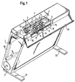
- Fig. 1
- eine perspektivische Ansicht von schräg oben auf ein erfindungsgemäßes Schneidegerät in teilweise ausgebrochener Darstellung,
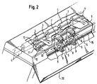
- Fig. 2
- eine vergrößerte Ansicht der Anordnung von Längsund Horizontalmessern gemäß der Fig. 1, und
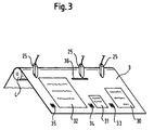
- Fig. 3
- eine schematische Darstellung einer Papierbahn mit darauf aufbelichteten Bildern und zugehörigen Strichcodes sowie mehreren Strichcodelesern.
- Fig. 1
- 2 shows a perspective view from obliquely above of a cutting device according to the invention in a partially broken-out representation,
- Fig. 2
- an enlarged view of the arrangement of longitudinal and horizontal knives according to FIG. 1, and
- Fig. 3
- is a schematic representation of a paper web with images exposed thereon and associated bar codes and a plurality of bar code readers.
Aus den Ansichten gemäß den Fig. 1 und 2 ist der wesentliche
Aufbau eines erfindungsgemäßen Schneidegerätes erkennbar.
Eine Papierbahn 3 mit darauf befindlichen Bildern 30, 31, 32
(wie es anhand der Fig. 3 später noch detaillierter erläutert
wird) ist als Rollenmaterial auf einer Spule 1 aufgewickelt.
Über der Spule 1 befinden sich Umlenkwalzen 2 für die
Papierbahn 3.From the views according to FIGS. 1 and 2 is the essential
Structure of a cutting device according to the invention recognizable.
A
Seitlich der Papierbahn sind Papierbahnführungen 16 oberhalb
der Umlenkwalzen 2 angeordnet, insbesondere sind sie
verschieblich ausführbar, um eine entsprechende Anpassung an
die Papierbahnbreite vornehmen zu können. Im oberen Bereich
des Schneidegerätes sind mehrere Transportwalzen 4 jeweils
paarweise nebeneinander angeordnet. Zwischen den
Transportwalzen 4 ist die Papierbahn 3 hindurchgeführt und
wird durch Antrieb der Transportwalzen 4 weiterbefördert.To the side of the paper web are paper web guides 16 above
the deflection rollers 2 arranged, in particular they are
slidably executable to adapt accordingly
to be able to make the paper web width. In the upper area
of the cutting device are several transport rollers 4 each
arranged in pairs next to each other. Between
Transport rollers 4, the
Unmittelbar nach den Transportwalzen 4 ist mindestens ein
Strichcodeleser 25 vorhanden. Bei der schematischen
Darstellung der Fig. 3 sind drei Strichcodeleser 25 über der
Papierbahn 3 angeordnet, es ist aber auch möglich,
beispielsweise nur einen ortsfesten oder einen verfahrbaren
Strichcodeleser 25 vorzusehen.Immediately after the transport rollers 4 is at least one
Hiernach ist eine Messerführung 11 angeordnet, die sich quer
über die Breite der Papierbahn 3 erstreckt. Auf dieser
Führung 11 ist ein Horizontalschlitten 13 motorisch
angetrieben verfahrbar. Auf diesem Schlitten 13 befindet sich
ein Horizontalschneidmesser 12, mit dem die Papierbahn 3
senkrecht zu deren Transportrichtung schneidbar ist. Bei
einer bevorzugten Ausführungsform ist dieses
Horizontalschneidmesser als Einfachmesser ausgebildet und
insbesondere als rotierendes Messer. After this, a
Dieser Längsschnittmesseranordnung 11, 12, 13 ist eine
Führung 14 für mehrere Längsschneidmesser 5 nachgeschaltet.
Die Führung 14 erstreckt sich wiederum über die gesamte
Papierbahnbreite um die Messer 5 daran motorisch angetrieben
verfahren zu können. Die Längsschneidmesser 5 umfassen
jeweils zwei Doppelschneidmesser zum Ausführung von zwei
nebeneinanderliegenden Schnitten längs zur Papierbahn 3. Sie
sind mittels eines Stellmotors 9 (Schrittmotor) motorisch
positionierbar. Hierzu ist eine Zahnstange 15 vorgesehen, in
die jeweilige, hier nicht sichtbare Zahnräder der
Antriebsmotoren 8 eingreifen. Außerdem sind eine
Antriebsspindel 10 für die Längsschneidmesser und an den
einzelnen Längsschneidmessern 5 Auswerfwalzen 6 vorgesehen.This
Dem nachgeschaltet ist am Gehäuse eine Papierablage 20
geschaffen. Das gesamte Gehäuse des Schneidegerätes ist hier
als Standgerät ausgebildet und weist zum Aufstellen Standfüße
21, 22 auf.This is followed by a
Nachfolgend wird die grundsätzliche Arbeitsweise dieses
Schneidegerätes beschrieben. Insbesondere wird hierzu auf die
Fig. 3 bezug genommen. Beim Aufbelichten der Papierbilder 30,
31, 32 auf die Papierbahn werden gleichzeitig jeweilige
Strichcodes 33, 34, 35 neben den einzelnen Bilder 30, 31, 32
aufbelichtet oder aufgedruckt. Wird nun eine derart
vorbereitete Papierbahnrolle in ein zuvor beschriebenes
Schneidegerät eingelegt, so wird mit Hilfe der
Transportwalzen 4 diese Papierbahn 3 an die
Schneideinrichtungen 5, 12 herangeführt. Bevor die einzelnen
Bilder in den Bereich der Schneideinrichtungen 5, 12 kommen,
werden mittels Strichcodelesern 25 die Daten bezüglich der
einzelnen Bilder 30, 31, 32 elektronisch ausgelesen, von
einer hier nicht dargestellten Steuereinheit ausgewählt und
entsprechend die einzelnen Messer 5, 12 positioniert. Damit
ist es möglich, unterschiedliche Breiten von Bildern, wie
auch Längen der Bilder zu berücksichtigen und die einzelnen
Bilder auszuschneiden. Diese werden dann durch die
Auswerfwalzen 4 austransportiert.Below is the basic operation of this
Cutting device described. In particular, this is based on the
Fig. 3 referred. When exposing the
Bei einer Gruppe von Bildern, wie es beispielsweise in der
Fig. 3 dargestellt ist, kann auch nur ein Strichcode 35
vorgesehen sein, der die Informationen der Gruppe von Bildern
30, 31, 32 beinhaltet. Es erfolgt dann ein Horizontalschnitt
entsprechend dem ersten und letzten Bildanfang bzw. Bildende,
so daß die gesamte Gruppe von Bildern ausgeschnitten wird.In the case of a group of images, such as in the
3, only one
Soll nur ein Strichcodeleser 25 eingesetzt werden, so ist der
Strichcode 35 immer an der gleichen Stelle beabstandet von
Rand der Papierbahn 3 zu plazieren. Es ist natürlich aber
auch möglich, den Strichcodeleser 25 beweglich anzuordnen.
Schließlich ist noch hervorzuheben, daß es selbstverständlich
auch möglich ist, nur einen Strichcode vorzusehen, in dem
aber dann die Daten für mehrere Bilder beinhaltet sind, so
daß dann über die Steuereinheit und die einzelnen
Schneideinrichtungen 5, 12 jedes Bild für sich
herausgeschnitten werden kann.If only one
Claims (20)
Priority Applications (1)
| Application Number | Priority Date | Filing Date | Title |
|---|---|---|---|
| DE29824430U DE29824430U1 (en) | 1998-03-31 | 1998-10-15 | Cutting device for cutting material webs with pictures on it as well as associated material web |
Applications Claiming Priority (2)
| Application Number | Priority Date | Filing Date | Title |
|---|---|---|---|
| IT1998BZ000013A IT1303482B1 (en) | 1998-03-31 | 1998-03-31 | PROCEDURE AND CUTTING DEVICE FOR BANDS OF RECANTIIMAGINI MATERIAL |
| ITBZ980013 | 1998-03-31 |
Publications (2)
| Publication Number | Publication Date |
|---|---|
| EP0947880A1 true EP0947880A1 (en) | 1999-10-06 |
| EP0947880B1 EP0947880B1 (en) | 2003-09-10 |
Family
ID=11346841
Family Applications (1)
| Application Number | Title | Priority Date | Filing Date |
|---|---|---|---|
| EP98119491A Expired - Lifetime EP0947880B1 (en) | 1998-03-31 | 1998-10-15 | Method and device for cutting webs of material provided with images |
Country Status (8)
| Country | Link |
|---|---|
| EP (1) | EP0947880B1 (en) |
| JP (1) | JPH11327116A (en) |
| AT (1) | ATE249636T1 (en) |
| AU (1) | AU2248699A (en) |
| CA (1) | CA2266751A1 (en) |
| DE (1) | DE59809569D1 (en) |
| ES (1) | ES2206807T3 (en) |
| IT (1) | IT1303482B1 (en) |
Cited By (7)
| Publication number | Priority date | Publication date | Assignee | Title |
|---|---|---|---|---|
| WO2006126224A1 (en) * | 2005-05-27 | 2006-11-30 | Fotoba International S.R.L. | Device for cutting paper and other graphic substrates wound in rolls on two perpendicular axes simultaneously with automatic errors correction |
| WO2008050357A1 (en) * | 2006-10-25 | 2008-05-02 | Fotoba International S.R.L. | Method for cutting paper and other graphic supports on a roll at the same time along two perpendicular axes with automatic correction of errors |
| CH703139A1 (en) * | 2010-05-14 | 2011-11-15 | Hunkeler Ag | Method and apparatus for longitudinal perforation of a moving web of material. |
| CN102744739A (en) * | 2012-07-09 | 2012-10-24 | 上海仰达机械有限公司 | Program controlled paper-cutting method using bar code to read cutting information |
| JP2013504446A (en) * | 2009-09-14 | 2013-02-07 | プリメーラ テクノロジー インコーポレイテッド | System for finishing printed labels using multiple XY cutters |
| ITUB20169898A1 (en) * | 2016-01-11 | 2017-07-11 | Fotoba Int S R L | METHOD AND AUTOMATIC SYSTEM FOR CUTTING SUBSTRATI WITH PRINTED IMAGES |
| IT201900011847A1 (en) | 2019-07-16 | 2021-01-16 | Fotoba Int S R L | PROCEDURE FOR CREATING A PRINTED SUPPORT AND RELATIVE PRINTING SYSTEM |
Families Citing this family (5)
| Publication number | Priority date | Publication date | Assignee | Title |
|---|---|---|---|---|
| US20060084005A1 (en) * | 2004-10-19 | 2006-04-20 | Eastman Kodak Company | Means to enable slitting of micro-encapsulated media |
| JP5228556B2 (en) * | 2008-03-22 | 2013-07-03 | 大日本印刷株式会社 | Random sewing machine verification equipment |
| JP7030289B2 (en) * | 2017-10-04 | 2022-03-07 | デュプロ精工株式会社 | Processing equipment |
| DE102017223730A1 (en) * | 2017-12-22 | 2019-06-27 | Texmag Gmbh Vertriebsgesellschaft | DEVICE AND METHOD FOR MACHINING A MATERIAL TRACK |
| KR102484440B1 (en) * | 2022-06-01 | 2023-01-04 | 오성시스템 주식회사 | Label printing apparatus with automatic label cutting function |
Citations (2)
| Publication number | Priority date | Publication date | Assignee | Title |
|---|---|---|---|---|
| US4506824A (en) * | 1982-02-17 | 1985-03-26 | Lucht Engineering, Inc. | Paper cutter |
| US4784318A (en) * | 1986-03-07 | 1988-11-15 | Otto Bay | Method and apparatus for cutting a paper or foil web into variously-sized rectangles |
-
1998
- 1998-03-31 IT IT1998BZ000013A patent/IT1303482B1/en active IP Right Grant
- 1998-10-15 EP EP98119491A patent/EP0947880B1/en not_active Expired - Lifetime
- 1998-10-15 ES ES98119491T patent/ES2206807T3/en not_active Expired - Lifetime
- 1998-10-15 AT AT98119491T patent/ATE249636T1/en not_active IP Right Cessation
- 1998-10-15 DE DE59809569T patent/DE59809569D1/en not_active Expired - Fee Related
-
1999
- 1999-03-24 CA CA002266751A patent/CA2266751A1/en not_active Abandoned
- 1999-03-29 AU AU22486/99A patent/AU2248699A/en not_active Abandoned
- 1999-03-31 JP JP11091948A patent/JPH11327116A/en active Pending
Patent Citations (2)
| Publication number | Priority date | Publication date | Assignee | Title |
|---|---|---|---|---|
| US4506824A (en) * | 1982-02-17 | 1985-03-26 | Lucht Engineering, Inc. | Paper cutter |
| US4784318A (en) * | 1986-03-07 | 1988-11-15 | Otto Bay | Method and apparatus for cutting a paper or foil web into variously-sized rectangles |
Cited By (12)
| Publication number | Priority date | Publication date | Assignee | Title |
|---|---|---|---|---|
| WO2006126224A1 (en) * | 2005-05-27 | 2006-11-30 | Fotoba International S.R.L. | Device for cutting paper and other graphic substrates wound in rolls on two perpendicular axes simultaneously with automatic errors correction |
| WO2008050357A1 (en) * | 2006-10-25 | 2008-05-02 | Fotoba International S.R.L. | Method for cutting paper and other graphic supports on a roll at the same time along two perpendicular axes with automatic correction of errors |
| US8051757B2 (en) | 2006-10-25 | 2011-11-08 | Fotoba International S.R.L. | Method for cutting paper and other graphic supports on a roll at the same time along two perpendicular axes with automatic correction of errors |
| JP2013504446A (en) * | 2009-09-14 | 2013-02-07 | プリメーラ テクノロジー インコーポレイテッド | System for finishing printed labels using multiple XY cutters |
| CH703139A1 (en) * | 2010-05-14 | 2011-11-15 | Hunkeler Ag | Method and apparatus for longitudinal perforation of a moving web of material. |
| EP2386389A1 (en) | 2010-05-14 | 2011-11-16 | Hunkeler AG | Method and device for longitudinally perforating a mobile sheet of material |
| CN102744739A (en) * | 2012-07-09 | 2012-10-24 | 上海仰达机械有限公司 | Program controlled paper-cutting method using bar code to read cutting information |
| CN102744739B (en) * | 2012-07-09 | 2015-01-28 | 上海仰达机械有限公司 | Program controlled paper-cutting method using bar code to read cutting information |
| ITUB20169898A1 (en) * | 2016-01-11 | 2017-07-11 | Fotoba Int S R L | METHOD AND AUTOMATIC SYSTEM FOR CUTTING SUBSTRATI WITH PRINTED IMAGES |
| WO2017122067A1 (en) * | 2016-01-11 | 2017-07-20 | Fotoba International S.R.L. | Automatic method and system for cutting substrates having printed images |
| IT201900011847A1 (en) | 2019-07-16 | 2021-01-16 | Fotoba Int S R L | PROCEDURE FOR CREATING A PRINTED SUPPORT AND RELATIVE PRINTING SYSTEM |
| CN114206624A (en) * | 2019-07-16 | 2022-03-18 | 弗托巴国际有限公司 | Method for producing printing carrier and related printing system |
Also Published As
| Publication number | Publication date |
|---|---|
| EP0947880B1 (en) | 2003-09-10 |
| AU2248699A (en) | 1999-10-14 |
| DE59809569D1 (en) | 2003-10-16 |
| ES2206807T3 (en) | 2004-05-16 |
| JPH11327116A (en) | 1999-11-26 |
| ITBZ980013A1 (en) | 1999-10-01 |
| CA2266751A1 (en) | 1999-09-30 |
| ATE249636T1 (en) | 2003-09-15 |
| IT1303482B1 (en) | 2000-11-06 |
Similar Documents
| Publication | Publication Date | Title |
|---|---|---|
| DE3103935C2 (en) | PRINT CONTROL DEVICE FOR A LABEL PRINTER | |
| DE3417042C2 (en) | ||
| DE2921337C2 (en) | Method for controlling the operating sequence in an automatic mail handling device and device for carrying out the method | |
| EP0947880A1 (en) | Method and device for cutting webs of material provided with images | |
| DE3300081A1 (en) | METHOD FOR PRINTING, EVALUATING AND CHECKING THE PRINT IMAGE OF A PRINTER AND DEVICE FOR PRINTING THIS METHOD | |
| DE3407258A1 (en) | METHOD AND DEVICE FOR DETERMINING THE EXACT POSITION OF A MOVABLE LINK | |
| EP0059169B1 (en) | Apparatus for preparing film strips for their manipulation in a printing apparatus | |
| DE602005004747T2 (en) | Positioning system and traversing carriage for slitter | |
| DE19654905A1 (en) | Cutting knife control method for till receipt printing arrangement | |
| DE3824090A1 (en) | LABEL DISPENSER | |
| DE102008021997B4 (en) | Beamsaw | |
| DE2638735C3 (en) | Arrangement for specifying the position of a positioning device | |
| DE3203943C2 (en) | ||
| EP3081927A1 (en) | Device for packaging loose medicament portions and method for the operation thereof | |
| DE3304649C2 (en) | ||
| DE4013836A1 (en) | METHOD FOR CUTTING OUT A CUT | |
| EP3221150B1 (en) | Device for producing cut objects | |
| DE102014004365B4 (en) | marking device | |
| EP0981444B1 (en) | Method and device for drawing in a strip of material | |
| DE4107801C2 (en) | Record carrier cutting device for printing or copying machines | |
| DE2328510C3 (en) | Device for feeding sheet-like recording media to typewriters and similar machines | |
| DE1288429B (en) | Machine for cutting microfilm strips into individual images in cards with an opening | |
| DE3119998C2 (en) | ||
| EP0690791B1 (en) | Document printing device with a device and process for print monitoring | |
| DE876804C (en) | Apparatus for the photographic typesetting of excluded lines of text |
Legal Events
| Date | Code | Title | Description |
|---|---|---|---|
| PUAI | Public reference made under article 153(3) epc to a published international application that has entered the european phase |
Free format text: ORIGINAL CODE: 0009012 |
|
| AK | Designated contracting states |
Kind code of ref document: A1 Designated state(s): AT BE CH CY DE DK ES FI FR GB LI NL PT SE |
|
| AX | Request for extension of the european patent |
Free format text: AL;LT;LV;MK;RO;SI |
|
| 17P | Request for examination filed |
Effective date: 19991208 |
|
| AKX | Designation fees paid |
Free format text: AT BE CH DE DK ES FR GB LI NL PT SE |
|
| RBV | Designated contracting states (corrected) |
Designated state(s): AT BE CH CY DE DK ES FI FR GB LI NL PT SE |
|
| 17Q | First examination report despatched |
Effective date: 20010323 |
|
| GRAG | Despatch of communication of intention to grant |
Free format text: ORIGINAL CODE: EPIDOS AGRA |
|
| GRAG | Despatch of communication of intention to grant |
Free format text: ORIGINAL CODE: EPIDOS AGRA |
|
| GRAG | Despatch of communication of intention to grant |
Free format text: ORIGINAL CODE: EPIDOS AGRA |
|
| GRAH | Despatch of communication of intention to grant a patent |
Free format text: ORIGINAL CODE: EPIDOS IGRA |
|
| GRAH | Despatch of communication of intention to grant a patent |
Free format text: ORIGINAL CODE: EPIDOS IGRA |
|
| GRAA | (expected) grant |
Free format text: ORIGINAL CODE: 0009210 |
|
| AK | Designated contracting states |
Kind code of ref document: B1 Designated state(s): AT BE CH CY DE DK ES FI FR GB LI NL PT SE |
|
| PG25 | Lapsed in a contracting state [announced via postgrant information from national office to epo] |
Ref country code: NL Free format text: LAPSE BECAUSE OF FAILURE TO SUBMIT A TRANSLATION OF THE DESCRIPTION OR TO PAY THE FEE WITHIN THE PRESCRIBED TIME-LIMIT Effective date: 20030910 Ref country code: FI Free format text: LAPSE BECAUSE OF FAILURE TO SUBMIT A TRANSLATION OF THE DESCRIPTION OR TO PAY THE FEE WITHIN THE PRESCRIBED TIME-LIMIT Effective date: 20030910 |
|
| REG | Reference to a national code |
Ref country code: GB Ref legal event code: FG4D Free format text: NOT ENGLISH |
|
| REG | Reference to a national code |
Ref country code: CH Ref legal event code: EP |
|
| PG25 | Lapsed in a contracting state [announced via postgrant information from national office to epo] |
Ref country code: CY Free format text: LAPSE BECAUSE OF FAILURE TO SUBMIT A TRANSLATION OF THE DESCRIPTION OR TO PAY THE FEE WITHIN THE PRESCRIBED TIME-LIMIT Effective date: 20031015 |
|
| REF | Corresponds to: |
Ref document number: 59809569 Country of ref document: DE Date of ref document: 20031016 Kind code of ref document: P |
|
| REG | Reference to a national code |
Ref country code: CH Ref legal event code: NV Representative=s name: ABP PATENT NETWORK SWISS GMBH |
|
| PG25 | Lapsed in a contracting state [announced via postgrant information from national office to epo] |
Ref country code: SE Free format text: LAPSE BECAUSE OF FAILURE TO SUBMIT A TRANSLATION OF THE DESCRIPTION OR TO PAY THE FEE WITHIN THE PRESCRIBED TIME-LIMIT Effective date: 20031210 Ref country code: DK Free format text: LAPSE BECAUSE OF FAILURE TO SUBMIT A TRANSLATION OF THE DESCRIPTION OR TO PAY THE FEE WITHIN THE PRESCRIBED TIME-LIMIT Effective date: 20031210 |
|
| PG25 | Lapsed in a contracting state [announced via postgrant information from national office to epo] |
Ref country code: PT Free format text: LAPSE BECAUSE OF FAILURE TO SUBMIT A TRANSLATION OF THE DESCRIPTION OR TO PAY THE FEE WITHIN THE PRESCRIBED TIME-LIMIT Effective date: 20031217 |
|
| GBT | Gb: translation of ep patent filed (gb section 77(6)(a)/1977) |
Effective date: 20031209 |
|
| NLV1 | Nl: lapsed or annulled due to failure to fulfill the requirements of art. 29p and 29m of the patents act | ||
| REG | Reference to a national code |
Ref country code: ES Ref legal event code: FG2A Ref document number: 2206807 Country of ref document: ES Kind code of ref document: T3 |
|
| ET | Fr: translation filed | ||
| PLBE | No opposition filed within time limit |
Free format text: ORIGINAL CODE: 0009261 |
|
| STAA | Information on the status of an ep patent application or granted ep patent |
Free format text: STATUS: NO OPPOSITION FILED WITHIN TIME LIMIT |
|
| 26N | No opposition filed |
Effective date: 20040614 |
|
| PGFP | Annual fee paid to national office [announced via postgrant information from national office to epo] |
Ref country code: AT Payment date: 20040923 Year of fee payment: 7 |
|
| PGFP | Annual fee paid to national office [announced via postgrant information from national office to epo] |
Ref country code: GB Payment date: 20041013 Year of fee payment: 7 |
|
| PGFP | Annual fee paid to national office [announced via postgrant information from national office to epo] |
Ref country code: DE Payment date: 20041014 Year of fee payment: 7 |
|
| PGFP | Annual fee paid to national office [announced via postgrant information from national office to epo] |
Ref country code: FR Payment date: 20041026 Year of fee payment: 7 |
|
| PGFP | Annual fee paid to national office [announced via postgrant information from national office to epo] |
Ref country code: CH Payment date: 20041108 Year of fee payment: 7 |
|
| PGFP | Annual fee paid to national office [announced via postgrant information from national office to epo] |
Ref country code: ES Payment date: 20041118 Year of fee payment: 7 |
|
| PGFP | Annual fee paid to national office [announced via postgrant information from national office to epo] |
Ref country code: BE Payment date: 20041217 Year of fee payment: 7 |
|
| PG25 | Lapsed in a contracting state [announced via postgrant information from national office to epo] |
Ref country code: GB Free format text: LAPSE BECAUSE OF NON-PAYMENT OF DUE FEES Effective date: 20051015 Ref country code: AT Free format text: LAPSE BECAUSE OF NON-PAYMENT OF DUE FEES Effective date: 20051015 |
|
| PG25 | Lapsed in a contracting state [announced via postgrant information from national office to epo] |
Ref country code: ES Free format text: LAPSE BECAUSE OF NON-PAYMENT OF DUE FEES Effective date: 20051017 |
|
| PG25 | Lapsed in a contracting state [announced via postgrant information from national office to epo] |
Ref country code: LI Free format text: LAPSE BECAUSE OF NON-PAYMENT OF DUE FEES Effective date: 20051031 Ref country code: CH Free format text: LAPSE BECAUSE OF NON-PAYMENT OF DUE FEES Effective date: 20051031 Ref country code: BE Free format text: LAPSE BECAUSE OF NON-PAYMENT OF DUE FEES Effective date: 20051031 |
|
| PG25 | Lapsed in a contracting state [announced via postgrant information from national office to epo] |
Ref country code: DE Free format text: LAPSE BECAUSE OF NON-PAYMENT OF DUE FEES Effective date: 20060503 |
|
| REG | Reference to a national code |
Ref country code: CH Ref legal event code: PL |
|
| GBPC | Gb: european patent ceased through non-payment of renewal fee |
Effective date: 20051015 |
|
| PG25 | Lapsed in a contracting state [announced via postgrant information from national office to epo] |
Ref country code: FR Free format text: LAPSE BECAUSE OF NON-PAYMENT OF DUE FEES Effective date: 20060630 |
|
| REG | Reference to a national code |
Ref country code: FR Ref legal event code: ST Effective date: 20060630 |
|
| REG | Reference to a national code |
Ref country code: ES Ref legal event code: FD2A Effective date: 20051017 |
|
| BERE | Be: lapsed |
Owner name: *DURST PHOTOTECHNIK A.G. Effective date: 20051031 |