EP0947586B1 - Verfahren und Vorrichtung zur schnellen Reduktion von Eisenerzen in einem Drehherdofen - Google Patents
Verfahren und Vorrichtung zur schnellen Reduktion von Eisenerzen in einem Drehherdofen Download PDFInfo
- Publication number
- EP0947586B1 EP0947586B1 EP98104960A EP98104960A EP0947586B1 EP 0947586 B1 EP0947586 B1 EP 0947586B1 EP 98104960 A EP98104960 A EP 98104960A EP 98104960 A EP98104960 A EP 98104960A EP 0947586 B1 EP0947586 B1 EP 0947586B1
- Authority
- EP
- European Patent Office
- Prior art keywords
- compacts
- hearth
- iron
- product
- furnace
- Prior art date
- Legal status (The legal status is an assumption and is not a legal conclusion. Google has not performed a legal analysis and makes no representation as to the accuracy of the status listed.)
- Expired - Lifetime
Links
Images

Classifications
-
- C—CHEMISTRY; METALLURGY
- C21—METALLURGY OF IRON
- C21B—MANUFACTURE OF IRON OR STEEL
- C21B13/00—Making spongy iron or liquid steel, by direct processes
- C21B13/10—Making spongy iron or liquid steel, by direct processes in hearth-type furnaces
- C21B13/105—Rotary hearth-type furnaces
-
- C—CHEMISTRY; METALLURGY
- C21—METALLURGY OF IRON
- C21B—MANUFACTURE OF IRON OR STEEL
- C21B13/00—Making spongy iron or liquid steel, by direct processes
- C21B13/0046—Making spongy iron or liquid steel, by direct processes making metallised agglomerates or iron oxide
-
- C—CHEMISTRY; METALLURGY
- C21—METALLURGY OF IRON
- C21B—MANUFACTURE OF IRON OR STEEL
- C21B13/00—Making spongy iron or liquid steel, by direct processes
- C21B13/10—Making spongy iron or liquid steel, by direct processes in hearth-type furnaces
-
- Y—GENERAL TAGGING OF NEW TECHNOLOGICAL DEVELOPMENTS; GENERAL TAGGING OF CROSS-SECTIONAL TECHNOLOGIES SPANNING OVER SEVERAL SECTIONS OF THE IPC; TECHNICAL SUBJECTS COVERED BY FORMER USPC CROSS-REFERENCE ART COLLECTIONS [XRACs] AND DIGESTS
- Y02—TECHNOLOGIES OR APPLICATIONS FOR MITIGATION OR ADAPTATION AGAINST CLIMATE CHANGE
- Y02P—CLIMATE CHANGE MITIGATION TECHNOLOGIES IN THE PRODUCTION OR PROCESSING OF GOODS
- Y02P10/00—Technologies related to metal processing
- Y02P10/10—Reduction of greenhouse gas [GHG] emissions
- Y02P10/134—Reduction of greenhouse gas [GHG] emissions by avoiding CO2, e.g. using hydrogen
Definitions
- the present invention relates to a method and apparatus for achieving rapid and efficient reduction of iron oxide in a rotary hearth furnace.
- U.S. 3,443,931 teaches a method of metallizing compacts of iron oxide containing a carbonaceous material.
- the compacts are formed, dried, and preindurated up to a temperature between 1600 and 1800°F (871 and 982 °C).
- the pellets are then rapidly heated by exposure to a radiant heat source which produces an environment at a temperature between 2300-2600°F (1260-1427 °C) for a sufficient time so that a liquidus phase is formed within the compacts. After the liquidus phase is formed, the compacts tend to shrink and then are immediately chilled by exposure to a cold environment.
- U.S. 3,452,972 teaches apparatus for a refractory furnace hearth having wustite (FeO) as a constituent thereof and the method of making such a refractory hearth.
- the subject furnace hearth has particular utility in the processing of iron oxide containing material, and is able to support such material during the reduction thereof without being destroyed during the process.
- Holley U.S. 3,836,353 teaches a method of recovering iron and oxide impurities from steel furnace dust in which the dust first is mixed with finely divided coke and then this mixture is pelletized.
- the green pellets thus formed are deposited over a layer of burnt pellets on a rotary hearth which successively conveys the pellets first through a drying zone, then through an initial heating zone in which the pellets are gradually raised to a temperature at which the coke starts to burn, then through a decontamination zone in which the pellet temperature is rapidly raised to a degree at which zinc, lead and sulfur impurities vaporize and in which these impurities are carried off and collected as oxides, and finally the pellets are carried through a reoxidation and hardening zone in which the temperature thereof is further increased to a sufficient degree and held for a long enough period of time to permit the growth of grains of an oxide of iron on the surface of the pellets, thus to form hard bonded pellets which are not fused together.
- the screw includes an outer shaft spatially circumscribing an inner tube.
- a plurality of hollow, fluid cooled flights are affixed to the outer shaft and are in fluid flow communication with coolant coursing through the screw. The coolant is first directed through the flights and then back through the outer shaft before exiting through the inner tube.
- Pargeter U.S. 4,676,741 teaches a radiantly heated, traveling hearth furnace having a supplementary feed means positioned intermediate the initial loading point and the final take-off point to increase the capacity of the furnace for treating objects fed thereto.
- the objects are pellets of iron oxide and carbonaceous reductant
- the provision of supplementary feed means about half-way along the travel path of the hearth promotes uniformity of product by inhibition of reoxidation of reduced iron by exposure to a fossil-fuel-fired furnace atmosphere.
- Kaneko et al. U.S. 4,701,214 teaches a method of producing iron from finely divided iron oxide comprising the steps of: mixing iron oxide or iron ore fines with finely divided coal and a binder to form a mixture, agglomerating the mixture by compacting, pelletizing, or briquetting the mixture to form agglomerates or pellets, introducing the pellets to a rotary hearth furnace to pre-reduce the iron in the pellets, introducing the pre-reduced pellets into a smelting reduction vessel as the metallic charge constituent, introducing particulate carbonaceous fuel and oxygen to the smelting reduction vessel through the bottom of the vessel to react with the melt or bath within the vessel, reduce the iron to elemental iron and form an off gas containing CO and H 2 , introducing the off-gas into the rotary hearth furnace as process gas to pre-reduce the pellets therein, and drawing off the hot metal from the smelting reduction vessel.
- the pre-reduced compacts are preferably discharged from the rotary hearth furnace at a temperature of at least 1000°C into the smelting reduction vessel to form the molten iron product.
- Kotraba et al. U.S. 5,186,741 teaches a pellet reclamation process includes forming green pellets of a mixture of steel furnace dust, a carbonaceous material such as coal, charcoal, lignite, petroleum coke, or coke, and an organic binder.
- the green pellets are fed over a layer of burnt pellets on a rotary hearth furnace which successively conveys the pellets first through a drying and coking zone in which the pellets are dried and any volatile matter driven out of the carbonaceous material.
- the pellets then travel through a reduction zone where the pellets are subjected to a higher temperature at which the contained iron oxide is reduced and remains within the pellets and the zinc, lead and cadmium oxides are reduced, volatilized, re-oxidized and carried off as oxides in the waste gases.
- the reduced pellets (DRI) are ultimately carried into a discharge zone where they are discharged from the rotary hearth furnace.
- An apparatus for performing the process is also disclosed.
- Rinker (US-A-5,601,631) discloses an apparatus for producing direct reduced iron from dry compacts of iron oxide and particulate carbonaceous material in a rotary hearth furnace.
- hot waste gas leaves the reduction zone of the rotary hearth furnace and is routed to a gas conditioner wherein residual carbon monoxide and volatile matter are further oxidized.
- Kundrat discloses a method and an apparatus for reducing metal oxide in a rotary hearth furnace heated by an oxidizing flame, in which a flue gas vent is located between a first feeding device and a second feeding device.
- This invention provides an improved method and apparatus for achieving rapid and efficient reduction of iron oxide in a rotary hearth furnace.
- Test results with this process which will be known by the trade name or trademark FASTMETTM, show that properly formed pellets (dry compacts) can be exposed immediately to a radiant heat source with a temperature of 1315-1430°C without causing exfoliation. Eliminating the low to medium temperature preheat zone and operating at high reduction temperature increases hearth productivity by 30 to 100% compared to other processes.
- energy efficiency can be improved by burning most of the volatiles released from the compacts inside the rotary furnace, and by causing the compacts and products of combustion to flow co-currently in the first portion of the furnace and counter-currently in the second portion of the furnace.
- the invention provides means for dividing rotary hearth gas flow into two portions rather than having the gas accumulate and peak at the feed area where dust is most likely to be entrained.
- the invention provides a low roof height in the initial heating zone of a rotary hearth furnace to enhance the radiative heat transfer to a layer of compacts on the hearth.
- the invention provides a rotary hearth furnace apparatus where the volatiles released from the compacts have a longer retention time, and can be more readily combusted.
- the invention provides a rotary hearth furnace with more efficient combustion than previously available, resulting in a lower ultimate gas volume requiring gas cleaning.
- the invention provides a rotary hearth furnace where the direction of the flue gas at the outlet is away from the hearth rather than sweeping across the hearth toward the side wall.
- the invention provides a rotary hearth furnace with a flue gas outlet of sufficient size to slow the gas velocity allowing entrained particles to fall back onto the hearth by gravity.
- the invention provides a rotary hearth furnace with improved atmosphere control at the hearth level to avoid oxidation of metallic iron.
- the invention provides a rotary hearth furnace apparatus for producing highly metallized iron having lower carbon content.
- the invention provides an improved rotary hearth furnace in which energy efficiency is improved by using sensible heat in the metallized compacts to preheat part of the fuel for the rotary hearth furnace.
- the invention provides a rotary hearth furnace capable of operating with a very short retention time of 4 to 10 minutes.
- the invention provides a rotary hearth furnace which avoids any disturbance of the protective blanket of carbon monoxide being evolved from the compacts in the final stages of reduction.
- the invention provides a rotary hearth furnace which maintains at least 1 percent excess carbon in the metallized compacts.
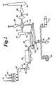
- Figure 1 is a schematic diagram of the process for an improved method of achieving rapid and efficient reduction of iron oxide in a rotary hearth furnace.
- Figure 2 is a cross sectional view of the improved rotary hearth furnace.
- Figure 3 is a top view of the improved rotary hearth furnace.
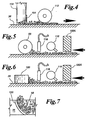
- Figure 4 is a schematic side view of the feed apparatus showing the feed or pellet leveler.
- Figure 5 is a schematic side view of the discharge portion of the apparatus showing a cooling device.
- Figure 6 is a schematic side view of the discharge portion of the apparatus showing a plow pellet discharge.
- Figure 7 is a schematic top view of the discharge portion of the apparatus of Figure 6.
- Feed bin 10 contains iron oxide materials 16 which are comprised of, but not limited to, finely divided iron ore fines, concentrate, by-product iron oxide and steel mill waste.
- Feed bin 12 contains carbonaceous materials 18 which are comprised of, but not limited to, pulverized coal, coke breeze, char, anthracite, charcoal and petroleum coke.
- Feed bin 14 contains binder materials 20 which are comprised of, but not limited to, organic binders, bentonite, or hydrated lime.
- agglomerating unit 26 which either pelletizes, briquettes, extrudes or compacts mixture 24 into consolidated units 28 which are then transported to a drying unit 30 and dried at approximately 120° to 180°C to remove moisture and form dry compacts 32.
- the dry compacts 32 are fed into a rotary hearth furnace (RHF) 34 through feed chute 102, which preferably can move vertically, and associated adjustable leveler gate 104, and deposited on the solid hearth 36, Figure 2, in a layer 38 one to two compacts deep.
- the hearth 36 shown in Figure 1 moves clockwise.
- the compacts pass under a radiation barrier 100 and are exposed to a radiant heat source 40 at a temperature of about 1315-1430°C for a period of 4 to 10 minutes during which time the volatiles and carbon monoxide are evolved from the compacts and combusted inside the furnace and most of the iron oxide is reduced to metallic iron and iron carbide.
- the metallic iron results from reducing, sintering, and/or partially melting the dry compacts.
- the compacts 38 are fed one to two compacts deep onto the hearth from at least one vertical feed pipe 102, which can have an adjustable gate 104, or leveler, having a lower edge to control the thickness of the layer of compacts.
- an independently mounted leveler 112 such as a water-cooled leveling roll, also shown in Figure 4, extends across the hearth 36 an appropriate height above the hearth just downstream from the feed pipe 102.
- the productivity (lb/h-ft 2 ) in a rotary hearth furnace 34 for a given feed material and hearth loading is inversely proportional to the retention time. For example, a retention time of 5.8 minutes should result in a productivity 31% higher than a retention time of 7.6 minutes.
- the temperature is kept uniformly high throughout all the heating zones of the furnace, it is not necessary to locate the flue duct near the feed end to take advantage of the sensible heat of the products of combustion.
- the flue gas temperature would be approximately the same regardless of the location of flue gas outlet 42 on the RHF 34. Therefore, it is possible to improve fuel efficiency, when using carbonaceous materials containing volatiles, by locating the flue gas outlet 42 at the mid-section of the RHF 34, between the charging and discharging locations. This results in the compacts and products of combustion flowing co-currently in the first portipn 44 of the RHF and counter-currently in the second portion 46 of the RHF.
- the gas flow through the RHF 34 is divided into two portions 47 and 48 rather than growing cumulatively and peaking at the feed area 102 of the RHF where dust is most likely to be entrained. This allows the height of the roof in the initial heating zone in the RHF 34 to be low due to the passage of low gas volume through the zone, thus enhancing the radiative heat transfer to the layer of compacts. Volatiles released from the compacts have a longer retention time inside the RHF and can be more readily combusted. The more efficient combustion inside the RHF lowers the ultimate volume of gas requiring gas cleaning.
- Locating the flue gas outlet 42 in the roof of the RHF 34 provides additional advantages like the direction of the flue gas at the outlet is away from the hearth rather than sweeping across the hearth toward the side wall.
- the flue gas outlet 42 can be made sufficiently large in diameter to slow the gas velocity down, allowing entrained particles to fall back onto the hearth by gravity.
- the high temperature radiant heat source 40 is initially generated by burning fuel.
- Burner fuel is provided from a source 50, the fuels used are, without limitation to natural gas, fuel oil, by-product gas and pulverized coal. This fuel is distributed to roof burners or wall mounted burners 52.
- Oxygen for combustion is supplied by preheated or oxygen enriched air 54. Additional preheated or oxygen enriched air is supplied to burn volatiles and CO evolved from the compacts. Efficient combustion is achieved due to the high operating temperature, and the longer retention time of volatiles and carbon monoxide inside the furnace due to locating the flue gas outlet 42 at the mid-section of the RHF 34 instead of at the feed end of the RHF.
- the atmosphere maintained inside the furnace is overall oxidizing to metallic iron. This allows the burners to operate more efficiently, resulting in lower fuel consumption and the flexibility to use fuels such as pulverized coal and fuel oil.
- the reduced iron is protected from oxidation by: operating with a very short retention time of 4 to 10 minutes; avoiding disturbance of the protective blanket of carbon monoxide being evolved from the compacts in the final stages of reduction; and maintaining at least 1 percent excess carbon in the metallized compacts.
- One method of partially cooling the metallized compacts is injecting a coolant from injector 116 on, or near, the compacts immediately prior to their discharge from the rotary hearth furnace.
- This coolant can comprise natural gas, pulverized coal, fuel oil or by-product gas.
- the coolant may dissociate into carbon and hydrogen. Some, or all, of the carbon may form carbon monoxide by reacting with carbon dioxide and water vapor. Free carbon deposited on the surface of the compacts will add further protection from oxidation. Reformed gases, carbon monoxide and hydrogen, provide additional blanket protection from the oxidizing products of combustion above the compacts.
- the dissociation and/or reforming of the coolant partially cools the hot compacts, transferring the heat to the reformed gases which are then allowed to be combusted in the rotary hearth furnace 34.
- the advantages of this method are: improved atmosphere control at the hearth level to avoid oxidation of metallic iron; highly metallized iron can be produced having lower carbon content; energy efficiency is improved by using sensible heat in the metallized compacts to preheat part of the fuel for the rotary hearth furnace.
- a second radiation barrier 100A is provided immediately prior to the cooling and discharge zone.
- a water cooled gas sampling probe 118 is installed inside the rotary hearth furnace to collect gas samples less than 2.54cm (one inch) above the surface of the compacts just prior to discharge.
- the rate of reduction begins to slow and the amount of carbon monoxide evolved begins to decrease.
- a high carbon monoxide level indicates the reduction rate is still high and product metallization may be low.
- a medium level of carbon monoxide indicates the reduction rate has slowed and product metallization is high.
- a low carbon monoxide level and/or presence of oxygen indicates the reduction rate has stopped and the product may be oxidized. Based on this knowledge, adjustments can be made to hearth speed, loading, temperature and/or atmosphere as necessary to maintain optimum productivity and product quality.
- the specific level of carbon monoxide and oxygen for the above three conditions must be calibrated for each furnace condition and feed mix.
- the metallized compacts are discharged from the hearth 36 via one or more helical water-cooled screws 56.
- the discharge device also levels the hearth.
- the hearth 36 is solid, is made of about 10.16 cm (4 inches) of the material being processed, and has wustite as a major constituent thereof. In this regard, it is a self-healing hearth. Any cracks or pits which develop are automatically filled with fresh fines without concern for buckling of the refractory underneath.
- Alternative means for discharging of compacts from the hearth comprises at least one plow 120, as shown in Figures 6 and 7.
- the plow may be either straight or curved.
- a plow discharge device also levels the hearth.
- the temperature of the discharged product 58 is approximately 900 to 1210°C.
- the product 58 can be hot charged into a melter 60, hot briquetted 62, or cooled 64 and stockpiled. If the discharged product is to be sent to a melter 60, then it may be placed in a transfer can 66 as hot direct reduced iron. It may also be desirable to send discharged product 58 to a briquetting press 68 for formation of hot briquetted iron. Alternatively discharged product 58 can be sent to a rotary drum cooler 70 which produces cold direct reduced iron.
- the reduction gas 72 after leaving the RHF 34 enters a flue gas conditioner 74.
- Conditioned gas 76 is transferred to a heat exchanger 78 which is also fed with combustion air 80 through fan 82.
- Heat exchanger 78 serves to warm combustion air 80 into preheated air 54.
- Pollution control equipment is comprised of scrubbers, electrostatic precipitators, cyclones, and bag houses.
- Treated gas 86 is drawn out of the pollution control equipment 84 by a fan 88 and delivered to a stack 90 for discharge to the atmosphere 92.
- the hearth is conventionally sealed to the hearth enclosure by a water seal 106, as described in Beggs US Patent 3,452,972.
- the annular hearth is supported on wheeled members 108 which can be driven by any conventional driving means, as shown in Beggs US Patent 3,452,972 or in Hanewald et al. US Patent
Claims (21)
- Ein Verfahren zum Erzeugen von direkt reduziertem Eisen aus Trockenpreßlingen, die aus Eisenoxid (16) und kohlenstoffhaltigem Material (18) bestehen und flüchtige Materialien enthalten, in einem Drehherdofen (34), wobei das Verfahren folgende Schritte umfaßt:Einführen der Preßlinge nicht mehr als zwei Preßlinge tief auf den Herd (36) des Drehherdofens (34);Entfernen aller flüchtigen Materialien durch Aussetzen der Preßlinge einer Strahlüngswärmequelle (40) bei einer Temperatur von etwa 1.315°C bis etwa 1.430°C für eine erste Zeitperiode von einer bis drei Minuten, und Aussetzen dieser Preßlinge einer oxidierenden Atmosphäre mit ausreichend freiem Sauerstoff, um die meisten der brennbaren Gase zu verbrennen, die während der ersten Zeitperiode entstehen und um verbrannte Gase zu bilden;Metallisieren der Preßlinge durch Aussetzen der Preßlinge einer Strahlungswärmequelle (40) bei einer Temperatur von etwa 1.315°C bis etwa 1.430°C in einer Atmosphäre ohne freien Sauerstoff für eine zweite Zeitperiode von drei bis neun Minuten;Bewirken, daß die Gase und die Preßlinge während der ersten Zeitperiode im Gleichstrom (44) fließen, und während der zweiten Zeitperiode im Gegenstrom fließen, und ein metallisiertes Eisenprodukt bilden; undEntnehmen des metallisierten Eisenprodukts von dem Herd (36).
- Ein Verfahren gemäß Anspruch 1, bei dem sich das Metallisieren der Preßlinge durch Reduzieren, Sintern oder teilweises Schmelzen der Trockenpreßlinge ergibt.
- Ein Verfahren gemäß Anspruch 1, das ferner das teilweise Kühlen der Preßlinge umfaßt, während dieselben von dem Herd (36) entnommen werden.
- Ein Verfahren gemäß Anspruch 1, bei dem das metallisierte Eisenprodukt für die letzten drei Minuten der zweiten Zeitperiode einer Atmosphäre ausgesetzt wird, die das metallische Eisen oxidiert, aber durch überschüssigen Kohlenstoff oder eine dünne Decke aus Kohlenstoffmonoxid und/oder Wasserstoff geschützt ist.
- Ein Verfahren gemäß Anspruch 1, das ferner das teilweise Abkühlen des metallisierten Eisenprodukts vor der Entnahme durch Injizieren eines Kühlmittels auf oder in der Nähe des metallisierten Eisenprodukts unmittelbar vor der Entnahme des metallisierten Eisenprodukts von dem Herd (36) umfaßt.
- Ein Verfahren gemäß Anspruch 5, bei dem das Kühlmittel aus der Gruppe ausgewählt ist, die aus natürlichem Gas, pulverisierter Kohle, Heizöl und Nebenproduktgas besteht.
- Ein Verfahren gemäß Anspruch 1, bei dem das Eisenoxid aus der Gruppe ausgewählt ist, die aus fein unterteilten Eisenerzen, Eisenoxidkonzentraten, Nebenprodukteisenoxiden und Stahlwerkabfällen besteht.
- Ein Verfahren gemäß Anspruch 1, bei dem das kohlenstoffhaltige Material (18) aus der Gruppe ausgewählt ist, die aus Kohle, Koksgrus, Petrolkoks, künstlicher Kohle und Holzkohlespänen besteht.
- Ein Verfahren gemäß Anspruch 1, bei dem das Eisenoxid und das kohlenstoffhaltige Material (18) in dem Preßling durch ein organisches Bindemittel (20) miteinander verbunden sind.
- Ein Verfahren gemäß Anspruch 1, bei dem die Energie für die Strahlungswärmequelle (40) zumindest teilweise durch das Verbrennen flüchtiger Materialien und durch Kohlenstoffmonoxid, das von den Preßlingen emittiert wird, geliefert wird.
- Ein Verfahren gemäß Anspruch 1, bei dem die Energie für die Strahlungswärmequelle (40) zumindest teilweise durch Verbrennen von Kraftstoff geliefert wird, der aus der Gruppe ausgewählt ist, die aus natürlichem Gas, pulverisierter Kohle, Heizöl und Nebenproduktgas besteht.
- Ein Verfahren gemäß Anspruch 1, bei dem Sauerstoff in den Ofen (34) eingeführt wird, um die Verbrennung zu unterstützen, wobei die Sauerstoffquelle aus der Gruppe ausgewählt ist, die aus vorgewärmter Luft, Sauerstoff und mit Sauerstoff angereicherter Luft besteht.
- Ein Verfahren gemäß Anspruch 1, bei dem die Anteile von Eisenoxid (16) und kohlenstoffhaltigem Material (18) in dem Preßling gesteuert werden, um ein konsistentes festes Kohlenstoff-zu-Eisen-Verhältnis beizubehalten.
- Ein Verfahren gemäß Anspruch 1, das ferner das Entnehmen des teilweise gekühlten metallisierten Eisenprodukts von dem Herd in einen Heißübertragungsbehälter (66) und das Heißladen des metallisierten Eisenprodukts in einen Schmelzofen (60) umfaßt.
- Ein Verfahren gemäß Anspruch 1, das ferner das Entnehmen des teilweise gekühlten metallisierten Eisenprodukts von dem Herd (36) in eine Brikettpresse (68) umfaßt, um heißbrikettiertes Eisen zu erzeugen.
- Vorrichtung zum Erzeugen von direkt reduziertem Eisen aus Trockenpreßlingen aus Eisenoxid (16) und partikulärem kohlenstoffhaltigen Material (18) in einem Drehherdofen (34), die folgende Merkmale umfaßt:a. eine Einrichtung (22) zum Mischen von Eisenoxidspänen und partikulärem kohlenstoffhaltigen Material und Bilden von Trockenpreßlingen;b. einen Drehherdofen (34) mit einer allgemeinen flachen Herdoberfläche zum Aufnehmen der Trockenpreßlinge;c. eine Einrichtung (102, 104; 112) zum Zuführen der Trockenrohlinge nicht mehr als zwei Rohlinge tief auf die Oberfläche des Herds (36);d. eine Einrichtung (40) zum Erwärmen, Reduzieren und Sintern oder teilweisen Schmelzen der Trokkenpreßlinge auf dem Herd, um ein reduziertes Produkt zu bilden;e. eine Einrichtung (56; 120) zum Entnehmen der reduzierten Preßlinge von dem Drehherdofen (34);f. eine Einrichtung (42) zwischen der Einführungseinrichtung (102, 104; 112) und der Entladeeinrichtung (56; 120) zum Entfernen von Rauchgas von dem Drehherdofen (34); undg. eine Einrichtung (116) zum Injizieren eines Kühlmittels auf oder in der Nähe des Preßlings unmittelbar vor der Entnahme der Preßlinge von dem Herd (36).
- Vorrichtung gemäß Anspruch 16, die ferner eine Einrichtung zum teilweisen Abkühlen der Preßlinge umfaßt, während dieselben von dem Herd (36) entnommen werden.
- Vorrichtung gemäß Anspruch 16, bei der die Einrichtung zum Zuführen der Preßlinge ein oder zwei Preßlinge tief auf den Herd zumindest eine einstellbare vertikale Zuführröhre (102) mit einem einstellbaren Tor (104) oder Abstreifer (112) umfaßt, der eine niedrigere Kante aufweist, um die Dicke der Preßlingsschicht zu steuern.
- Vorrichtung gemäß Anspruch 16, bei der die Einrichtung zum Entnehmen von Preßlingen von dem Herd zumindest eine Schraubenfeder (56) umfaßt.
- Vorrichtung gemäß Anspruch 16, bei der die Einrichtung zum Entnehmen der Preßlinge von dem Herd zumindest einen Hobel (120) umfaßt.
- Vorrichtung gemäß Anspruch 16, die ferner eine wassergekühlte Sonde (118) umfaßt, zum Sammeln einer Gasprobe weniger als 2,54 cm (1 Zoll) über der Oberfläche der Preßlinge unmittelbar vor deren Entnahme von dem Herd (36), wobei die Pegel von Kohlenstoffmonoxid und Sauerstoff in der Gasprobe zu Zwecken der Produktqualitätssteuerung und/oder Optimierung der Produktivität überwacht werden.
Priority Applications (9)
| Application Number | Priority Date | Filing Date | Title |
|---|---|---|---|
| US08/357,940 US5730775A (en) | 1994-12-16 | 1994-12-16 | Method for rapid reduction of iron oxide in a rotary hearth furnace |
| AU67605/98A AU6760598A (en) | 1994-12-16 | 1998-03-13 | Method and apparatus for rapid reduction of iron oxide in a rotary hearth furnace |
| PCT/US1998/005006 WO1999046410A1 (en) | 1994-12-16 | 1998-03-13 | Method and apparatus for rapid reduction of iron oxide in a rotary hearth furnace |
| CA002232275A CA2232275C (en) | 1994-12-16 | 1998-03-17 | Method and apparatus for rapid reduction of iron oxide in a rotary hearth furnace |
| DE69809883T DE69809883T2 (de) | 1994-12-16 | 1998-03-18 | Verfahren und Vorrichtung zur schnellen Reduktion von Eisenerzen in einem Drehherdofen |
| EP98104960A EP0947586B1 (de) | 1994-12-16 | 1998-03-18 | Verfahren und Vorrichtung zur schnellen Reduktion von Eisenerzen in einem Drehherdofen |
| AT98104960T ATE229084T1 (de) | 1994-12-16 | 1998-03-18 | Verfahren und vorrichtung zur schnellen reduktion von eisenerzen in einem drehherdofen |
| ES98104960T ES2189022T3 (es) | 1994-12-16 | 1998-03-18 | Metodo y aparato para la reduccion rapida del oxido de hierro en un horno de solera giratoria. |
| TW087104297A TW442573B (en) | 1994-12-16 | 1998-03-23 | Method for producing direct reduced iron from dry compacts, and apparatus for producing metal from direct reduced iron from dry compacts in a rotary hearth furnace |
Applications Claiming Priority (6)
| Application Number | Priority Date | Filing Date | Title |
|---|---|---|---|
| US08/357,940 US5730775A (en) | 1994-12-16 | 1994-12-16 | Method for rapid reduction of iron oxide in a rotary hearth furnace |
| US08/832,414 US5885521A (en) | 1994-12-16 | 1997-04-02 | Apparatus for rapid reduction of iron oxide in a rotary hearth furnace |
| PCT/US1998/005006 WO1999046410A1 (en) | 1994-12-16 | 1998-03-13 | Method and apparatus for rapid reduction of iron oxide in a rotary hearth furnace |
| CA002232275A CA2232275C (en) | 1994-12-16 | 1998-03-17 | Method and apparatus for rapid reduction of iron oxide in a rotary hearth furnace |
| EP98104960A EP0947586B1 (de) | 1994-12-16 | 1998-03-18 | Verfahren und Vorrichtung zur schnellen Reduktion von Eisenerzen in einem Drehherdofen |
| TW087104297A TW442573B (en) | 1994-12-16 | 1998-03-23 | Method for producing direct reduced iron from dry compacts, and apparatus for producing metal from direct reduced iron from dry compacts in a rotary hearth furnace |
Publications (2)
| Publication Number | Publication Date |
|---|---|
| EP0947586A1 EP0947586A1 (de) | 1999-10-06 |
| EP0947586B1 true EP0947586B1 (de) | 2002-12-04 |
Family
ID=33437265
Family Applications (1)
| Application Number | Title | Priority Date | Filing Date |
|---|---|---|---|
| EP98104960A Expired - Lifetime EP0947586B1 (de) | 1994-12-16 | 1998-03-18 | Verfahren und Vorrichtung zur schnellen Reduktion von Eisenerzen in einem Drehherdofen |
Country Status (9)
| Country | Link |
|---|---|
| US (1) | US5730775A (de) |
| EP (1) | EP0947586B1 (de) |
| AT (1) | ATE229084T1 (de) |
| AU (1) | AU6760598A (de) |
| CA (1) | CA2232275C (de) |
| DE (1) | DE69809883T2 (de) |
| ES (1) | ES2189022T3 (de) |
| TW (1) | TW442573B (de) |
| WO (1) | WO1999046410A1 (de) |
Cited By (2)
| Publication number | Priority date | Publication date | Assignee | Title |
|---|---|---|---|---|
| CN1763231B (zh) * | 2000-03-30 | 2010-07-28 | 米德雷克斯国际公司苏黎世分公司 | 生产金属铁的方法 |
| RU2442826C2 (ru) * | 2006-11-14 | 2012-02-20 | Кабусики Кайся Кобе Сейко Се | Способ и устройство для получения гранулированного металлического железа |
Families Citing this family (58)
| Publication number | Priority date | Publication date | Assignee | Title |
|---|---|---|---|---|
| AUPN461695A0 (en) * | 1995-08-07 | 1995-08-31 | Technological Resources Pty Limited | A process for reducing iron oxides |
| CN1080315C (zh) | 1996-03-15 | 2002-03-06 | 株式会社神户制钢所 | 生产金属铁的方法及设备 |
| US6506231B2 (en) | 1996-03-15 | 2003-01-14 | Kabushiki Kaisha Kobe Seiko Sho | Method and apparatus for making metallic iron |
| JP3296974B2 (ja) * | 1996-08-15 | 2002-07-02 | 株式会社神戸製鋼所 | 直接還元法及び回転床炉 |
| WO1998021372A1 (fr) * | 1996-11-11 | 1998-05-22 | Sumitomo Metal Industries, Ltd. | Procede et dispositif de fabrication de fer reduit |
| US5951740A (en) * | 1997-06-16 | 1999-09-14 | Praxair Technology, Inc. | Production of direct reduced iron with reduced fuel consumption and emission of carbon monoxide |
| EP1770175A1 (de) * | 1997-09-30 | 2007-04-04 | JFE Steel Corporation | Drehherdofen zur Reduktion der Oxide |
| JP3845978B2 (ja) * | 1997-09-30 | 2006-11-15 | Jfeスチール株式会社 | 回転炉床炉の操業方法および回転炉床炉 |
| ID26484A (id) * | 1997-12-26 | 2001-01-11 | Nippon Kokan Kk | Metode pemurnian besi lelehan dan metode reduksi pelelehan untuk memproduksi besi lelehan |
| JP3081581B2 (ja) * | 1998-03-23 | 2000-08-28 | 株式会社神戸製鋼所 | 高金属化率還元鉄塊成物の製造方法 |
| EP0952230A1 (de) * | 1998-03-24 | 1999-10-27 | KABUSHIKI KAISHA KOBE SEIKO SHO also known as Kobe Steel Ltd. | Verfahren zur Herstellung von reduzierten Eisenagglomeraten |
| US6120577A (en) * | 1998-03-25 | 2000-09-19 | Ltv Steel Company, Inc. | Treatment of steel mill waste metal oxides |
| JP2997459B1 (ja) * | 1998-11-04 | 2000-01-11 | 株式会社神戸製鋼所 | 還元鉄塊成物の製造方法 |
| TW502066B (en) | 1998-08-27 | 2002-09-11 | Kobe Steel Ltd | Method for operating moving hearth reducing furnace |
| TW461920B (en) | 1998-09-25 | 2001-11-01 | Mitsubishi Heavy Ind Ltd | Method of producing reduced iron and production facilities therefor |
| US6685761B1 (en) | 1998-10-30 | 2004-02-03 | Midrex International B.V. Rotterdam, Zurich Branch | Method for producing beneficiated titanium oxides |
| AU761344B2 (en) * | 1998-10-30 | 2003-06-05 | Midrex Technologies Inc. | Method of producing molten iron in duplex furnaces |
| US6413295B2 (en) | 1998-11-12 | 2002-07-02 | Midrex International B.V. Rotterdam, Zurich Branch | Iron production method of operation in a rotary hearth furnace and improved furnace apparatus |
| JP3404309B2 (ja) * | 1999-01-18 | 2003-05-06 | 株式会社神戸製鋼所 | 還元鉄塊成物の製造方法および製造装置 |
| US6390810B1 (en) | 1999-03-15 | 2002-05-21 | Maumee Research & Engineering, Inc. | Method and apparatus for reducing a feed material in a rotary hearth furnace |
| BR9917437A (pt) * | 1999-07-28 | 2002-06-18 | Sidmar Nv | Processo e forno de redução de óxidos metálicos |
| CN1276097C (zh) | 1999-08-30 | 2006-09-20 | 株式会社神户制钢所 | 粒状还原铁原料的供给方法及其装置 |
| JP4227710B2 (ja) | 1999-09-17 | 2009-02-18 | 三菱重工業株式会社 | 還元鉄製造装置 |
| US6368104B1 (en) * | 1999-09-24 | 2002-04-09 | The Boc Group, Inc. | Rotary hearth furnace |
| RU2228365C2 (ru) | 2000-03-30 | 2004-05-10 | Мидрекс Интернэшнл Б.В. Цюрих Бранч | Способ получения гранулированного металлического железа, способ получения жидкой стали, способ получения металлического железа, устройство для загрузки вспомогательного исходного материала и устройство для загрузки исходного материала |
| TW562860B (en) | 2000-04-10 | 2003-11-21 | Kobe Steel Ltd | Method for producing reduced iron |
| US6802886B2 (en) * | 2000-06-05 | 2004-10-12 | Midrex Technologies, Inc. | Method of producing a metallized briquette |
| JP2002020813A (ja) * | 2000-07-05 | 2002-01-23 | Mitsubishi Heavy Ind Ltd | 還元鉄製造装置 |
| EP1338660B1 (de) * | 2000-10-30 | 2009-05-13 | Nippon Steel Corporation | METALLOXID ENTHALTENDES GRÜNPELLET FÜR REDUKTIONSOFEN und VERFAHREN ZU SEINER HERSTELLUNG, VERFAHREN ZU SEINER REDUKTION |
| US7037356B2 (en) * | 2000-11-10 | 2006-05-02 | Nippon Steel Corporation | Method for operating rotary hearth type reducing furnace and rotary hearth type reducing furnace facilities |
| US6749664B1 (en) | 2001-01-26 | 2004-06-15 | Midrex International, B.V., Rotterdam, Zurich Branch | Furnace hearth for improved molten iron production and method of operation |
| JP2002363626A (ja) * | 2001-06-11 | 2002-12-18 | Kobe Steel Ltd | 移動炉床炉の操業方法 |
| US6993855B2 (en) * | 2001-09-27 | 2006-02-07 | Nippon Steel Corporation | Method for drying compact containing metal oxide, method for reducing metal oxide, and rotary-hearth-type metal reducing furnace |
| US8197561B2 (en) * | 2001-10-10 | 2012-06-12 | River Basin Energy, Inc. | Process for drying coal |
| AU2003230680A1 (en) * | 2002-03-19 | 2003-10-08 | Superior Graphite Co. | Process and apparatus for the direct reduction of iron oxides in an electrothermal fluidized bed and resulant product |
| JP4307849B2 (ja) * | 2003-01-07 | 2009-08-05 | 株式会社神戸製鋼所 | クロム含有原料の還元方法 |
| JP4490640B2 (ja) * | 2003-02-26 | 2010-06-30 | 株式会社神戸製鋼所 | 還元金属の製造方法 |
| AU2003903344A0 (en) * | 2003-06-30 | 2003-07-17 | Furnace Engineering Pty Ltd | High temperature process |
| AU2004252178B2 (en) * | 2003-06-30 | 2009-10-08 | Furnace Engineering Pty Ltd | High temperature process |
| CA2590259C (en) * | 2004-12-07 | 2016-02-16 | Nu-Iron Technology, Llc | Method and system for producing metallic iron nuggets |
| US8470068B2 (en) * | 2004-12-07 | 2013-06-25 | Nu-Iron Technology, Llc | Method and system for producing metallic iron nuggets |
| CA2616394A1 (en) * | 2005-08-30 | 2007-03-08 | E.I. Du Pont De Nemours And Company | Ore reduction process and titanium oxide and iron metallization product |
| US8021460B2 (en) * | 2006-07-26 | 2011-09-20 | Nu-Iron Technology, Llc | System and method for producing metallic iron nodules |
| JP5059379B2 (ja) * | 2006-11-16 | 2012-10-24 | 株式会社神戸製鋼所 | 高炉装入原料用ホットブリケットアイアンおよびその製造方法 |
| US7938882B2 (en) * | 2007-04-02 | 2011-05-10 | Midrex Technologies, Inc. | Method and system for the supply of hot direct reduced iron for multiple uses |
| JP4317579B2 (ja) | 2007-09-05 | 2009-08-19 | 新日本製鐵株式会社 | 還元鉄成形体の製造方法、及び銑鉄の製造方法 |
| US8372179B2 (en) * | 2007-10-15 | 2013-02-12 | E I Du Pont De Nemours And Company | Ore reduction process using carbon based materials having a low sulfur content and titanium oxide and iron metallization product therefrom |
| EP2325341A1 (de) | 2008-01-30 | 2011-05-25 | Nu-Iron Technology, Inc | Verfahren und System zur Herstellung metallischer Ionenklumpen |
| CA2661419A1 (en) | 2008-04-03 | 2009-10-03 | Nu-Iron Technology, Llc | System and method for producing metallic iron |
| CZ200975A3 (cs) | 2009-02-10 | 2010-08-04 | Raclavský@Milan | Technologie rafinace kovonosných odpadu s obsahem zinku v rotacní peci |
| WO2011041431A1 (en) | 2009-09-29 | 2011-04-07 | Nu-Iron Technology, Llc | System and method for producing metallic iron |
| US9057037B2 (en) | 2010-04-20 | 2015-06-16 | River Basin Energy, Inc. | Post torrefaction biomass pelletization |
| US8956426B2 (en) * | 2010-04-20 | 2015-02-17 | River Basin Energy, Inc. | Method of drying biomass |
| US8287621B2 (en) | 2010-12-22 | 2012-10-16 | Nu-Iron Technology, Llc | Use of bimodal carbon distribution in compacts for producing metallic iron nodules |
| JP5677884B2 (ja) * | 2011-04-11 | 2015-02-25 | 新日鉄住金エンジニアリング株式会社 | 連続加熱処理炉の炉温設定方法及び炉温制御方法 |
| JP5957348B2 (ja) * | 2012-09-21 | 2016-07-27 | Primetals Technologies Japan株式会社 | 部分還元鉄製造装置 |
| US9534275B2 (en) | 2013-03-06 | 2017-01-03 | Midrex Technologies, Inc. | Methods and systems for reducing chromium containing raw material |
| EP3986596B1 (de) | 2019-08-23 | 2023-07-12 | John W. SCHULTES | Verfahren und eine direkte reduzierungsanlage zur herstellung von direkt reduziertem eisen |
Family Cites Families (12)
| Publication number | Priority date | Publication date | Assignee | Title |
|---|---|---|---|---|
| US3443931A (en) * | 1965-09-10 | 1969-05-13 | Midland Ross Corp | Process for making metallized pellets from iron oxide containing material |
| US3452972A (en) * | 1966-06-23 | 1969-07-01 | Donald Beggs | Furnace hearth |
| US3836353A (en) * | 1968-10-18 | 1974-09-17 | C Holley | Pellet reclamation process |
| US3988012A (en) * | 1972-02-16 | 1976-10-26 | Emile Joseph Jemal | Rotary hearth |
| US4622905A (en) * | 1985-03-04 | 1986-11-18 | International Metals Reclamation Co., Inc. | Furnacing |
| US4636127A (en) * | 1985-04-03 | 1987-01-13 | The International Metals Reclamation Co., Inc. | Conveying screw for furnace |
| US4597564A (en) * | 1985-05-23 | 1986-07-01 | The International Metals Reclamation Company, Inc. | Rotary hearth |
| US4701214A (en) * | 1986-04-30 | 1987-10-20 | Midrex International B.V. Rotterdam | Method of producing iron using rotary hearth and apparatus |
| US4676741A (en) * | 1986-10-22 | 1987-06-30 | The International Metals Reclamation Company, Inc. | Radiantly heated furnace |
| US5186741A (en) * | 1991-04-12 | 1993-02-16 | Zia Patent Company | Direct reduction process in a rotary hearth furnace |
| US5567224A (en) * | 1995-06-06 | 1996-10-22 | Armco Inc. | Method of reducing metal oxide in a rotary hearth furnace heated by an oxidizing flame |
| US5601631A (en) * | 1995-08-25 | 1997-02-11 | Maumee Research & Engineering Inc. | Process for treating metal oxide fines |
-
1994
- 1994-12-16 US US08/357,940 patent/US5730775A/en not_active Expired - Lifetime
-
1998
- 1998-03-13 WO PCT/US1998/005006 patent/WO1999046410A1/en active Application Filing
- 1998-03-13 AU AU67605/98A patent/AU6760598A/en not_active Abandoned
- 1998-03-17 CA CA002232275A patent/CA2232275C/en not_active Expired - Lifetime
- 1998-03-18 ES ES98104960T patent/ES2189022T3/es not_active Expired - Lifetime
- 1998-03-18 AT AT98104960T patent/ATE229084T1/de active
- 1998-03-18 EP EP98104960A patent/EP0947586B1/de not_active Expired - Lifetime
- 1998-03-18 DE DE69809883T patent/DE69809883T2/de not_active Expired - Lifetime
- 1998-03-23 TW TW087104297A patent/TW442573B/zh not_active IP Right Cessation
Cited By (2)
| Publication number | Priority date | Publication date | Assignee | Title |
|---|---|---|---|---|
| CN1763231B (zh) * | 2000-03-30 | 2010-07-28 | 米德雷克斯国际公司苏黎世分公司 | 生产金属铁的方法 |
| RU2442826C2 (ru) * | 2006-11-14 | 2012-02-20 | Кабусики Кайся Кобе Сейко Се | Способ и устройство для получения гранулированного металлического железа |
Also Published As
| Publication number | Publication date |
|---|---|
| DE69809883D1 (de) | 2003-01-16 |
| US5730775A (en) | 1998-03-24 |
| DE69809883T2 (de) | 2003-10-09 |
| CA2232275C (en) | 2001-10-23 |
| WO1999046410A1 (en) | 1999-09-16 |
| TW442573B (en) | 2001-06-23 |
| ATE229084T1 (de) | 2002-12-15 |
| CA2232275A1 (en) | 1999-09-17 |
| AU6760598A (en) | 1999-09-27 |
| ES2189022T3 (es) | 2003-07-01 |
| EP0947586A1 (de) | 1999-10-06 |
Similar Documents
| Publication | Publication Date | Title |
|---|---|---|
| EP0947586B1 (de) | Verfahren und Vorrichtung zur schnellen Reduktion von Eisenerzen in einem Drehherdofen | |
| US5885521A (en) | Apparatus for rapid reduction of iron oxide in a rotary hearth furnace | |
| CA2061548C (en) | Direct reduction process in rotary hearth furnace | |
| US5865875A (en) | Process for treating metal oxide fines | |
| SU1674694A3 (ru) | Способ получени расплавленных железосодержащих материалов из тонкоизмельченной руды и устройство дл его осуществлени | |
| US6015527A (en) | Facility for producing reduced iron | |
| EP1026265B1 (de) | Verfahren zum Herstellen von reduziertem Eisen und Drehherdofen zu seiner Herstellung | |
| US20080087135A1 (en) | Microwave heating method and apparatus for iron oxide reduction | |
| CA1224516A (en) | Electric arc fired cupola for remelting of metal chips | |
| CN108796217B (zh) | 一种含锌含铁尘泥资源化利用的装置及方法 | |
| EP0442040B1 (de) | Verfahren und Vorrichtung zur Direktreduktion von Metalloxyden | |
| US20100107818A1 (en) | System and method for producing metallic iron nodules | |
| EP0387479B1 (de) | Verfahren und Anlage zur Rückgewinnung von NE-Metallen mittels eines Schachtofens mit kontinuierlicher Zufuhr | |
| JP3304872B2 (ja) | 回転炉床式加熱炉内における酸化鉄の急速還元方法及び装置 | |
| US8287621B2 (en) | Use of bimodal carbon distribution in compacts for producing metallic iron nodules | |
| US6270551B1 (en) | Process for treating metal oxide fines | |
| US6602322B2 (en) | High temperature metal recovery process | |
| US4238222A (en) | Waelz process of volatilizing zinc and lead from iron oxide-containing materials | |
| AU726912B2 (en) | Method and apparatus for rapid reduction of iron oxide in a rotary hearth furnace | |
| US3832158A (en) | Process for producing metal from metal oxide pellets in a cupola type vessel | |
| US3196000A (en) | Process for the direct reduction of iron ores in rotating cylindrical furnaces | |
| JP3451901B2 (ja) | 移動型炉床炉の操業方法 | |
| KR100326006B1 (ko) | 로타리화덕노내에서산화철의신속환원를위한방법및그장치 |
Legal Events
| Date | Code | Title | Description |
|---|---|---|---|
| PUAI | Public reference made under article 153(3) epc to a published international application that has entered the european phase |
Free format text: ORIGINAL CODE: 0009012 |
|
| 17P | Request for examination filed |
Effective date: 19981217 |
|
| AK | Designated contracting states |
Kind code of ref document: A1 Designated state(s): AT BE DE ES FR GB IT LU NL |
|
| AX | Request for extension of the european patent |
Free format text: AL;LT;LV;MK;RO;SI |
|
| RAP1 | Party data changed (applicant data changed or rights of an application transferred) |
Owner name: MIDREX DIRECT REDUCTION CORPORATION |
|
| AKX | Designation fees paid |
Free format text: AT BE DE ES FR GB IT LU NL |
|
| 17Q | First examination report despatched |
Effective date: 20001017 |
|
| RAP1 | Party data changed (applicant data changed or rights of an application transferred) |
Owner name: MIDREX TECHNOLOGIES, INC. |
|
| GRAG | Despatch of communication of intention to grant |
Free format text: ORIGINAL CODE: EPIDOS AGRA |
|
| GRAG | Despatch of communication of intention to grant |
Free format text: ORIGINAL CODE: EPIDOS AGRA |
|
| GRAH | Despatch of communication of intention to grant a patent |
Free format text: ORIGINAL CODE: EPIDOS IGRA |
|
| GRAH | Despatch of communication of intention to grant a patent |
Free format text: ORIGINAL CODE: EPIDOS IGRA |
|
| GRAA | (expected) grant |
Free format text: ORIGINAL CODE: 0009210 |
|
| AK | Designated contracting states |
Kind code of ref document: B1 Designated state(s): AT BE DE ES FR GB IT LU NL |
|
| REF | Corresponds to: |
Ref document number: 229084 Country of ref document: AT Date of ref document: 20021215 Kind code of ref document: T |
|
| REG | Reference to a national code |
Ref country code: GB Ref legal event code: FG4D |
|
| REF | Corresponds to: |
Ref document number: 69809883 Country of ref document: DE Date of ref document: 20030116 |
|
| REG | Reference to a national code |
Ref country code: ES Ref legal event code: FG2A Ref document number: 2189022 Country of ref document: ES Kind code of ref document: T3 |
|
| ET | Fr: translation filed | ||
| PLBE | No opposition filed within time limit |
Free format text: ORIGINAL CODE: 0009261 |
|
| STAA | Information on the status of an ep patent application or granted ep patent |
Free format text: STATUS: NO OPPOSITION FILED WITHIN TIME LIMIT |
|
| 26N | No opposition filed |
Effective date: 20030905 |
|
| REG | Reference to a national code |
Ref country code: FR Ref legal event code: PLFP Year of fee payment: 19 |
|
| PGFP | Annual fee paid to national office [announced via postgrant information from national office to epo] |
Ref country code: NL Payment date: 20160307 Year of fee payment: 19 Ref country code: LU Payment date: 20160316 Year of fee payment: 19 |
|
| PGFP | Annual fee paid to national office [announced via postgrant information from national office to epo] |
Ref country code: FR Payment date: 20160223 Year of fee payment: 19 |
|
| PGFP | Annual fee paid to national office [announced via postgrant information from national office to epo] |
Ref country code: BE Payment date: 20170314 Year of fee payment: 20 Ref country code: AT Payment date: 20170223 Year of fee payment: 20 Ref country code: GB Payment date: 20170223 Year of fee payment: 20 |
|
| PGFP | Annual fee paid to national office [announced via postgrant information from national office to epo] |
Ref country code: IT Payment date: 20170309 Year of fee payment: 20 Ref country code: ES Payment date: 20170308 Year of fee payment: 20 |
|
| PGFP | Annual fee paid to national office [announced via postgrant information from national office to epo] |
Ref country code: DE Payment date: 20170331 Year of fee payment: 20 |
|
| REG | Reference to a national code |
Ref country code: NL Ref legal event code: MM Effective date: 20170401 |
|
| REG | Reference to a national code |
Ref country code: FR Ref legal event code: ST Effective date: 20171130 |
|
| PG25 | Lapsed in a contracting state [announced via postgrant information from national office to epo] |
Ref country code: FR Free format text: LAPSE BECAUSE OF NON-PAYMENT OF DUE FEES Effective date: 20170331 Ref country code: NL Free format text: LAPSE BECAUSE OF NON-PAYMENT OF DUE FEES Effective date: 20170401 Ref country code: LU Free format text: LAPSE BECAUSE OF NON-PAYMENT OF DUE FEES Effective date: 20170318 |
|
| REG | Reference to a national code |
Ref country code: DE Ref legal event code: R071 Ref document number: 69809883 Country of ref document: DE |
|
| REG | Reference to a national code |
Ref country code: BE Ref legal event code: MK Effective date: 20180318 |
|
| REG | Reference to a national code |
Ref country code: GB Ref legal event code: PE20 Expiry date: 20180317 |
|
| PG25 | Lapsed in a contracting state [announced via postgrant information from national office to epo] |
Ref country code: GB Free format text: LAPSE BECAUSE OF EXPIRATION OF PROTECTION Effective date: 20180317 |
|
| REG | Reference to a national code |
Ref country code: AT Ref legal event code: MK07 Ref document number: 229084 Country of ref document: AT Kind code of ref document: T Effective date: 20180318 |
|
| REG | Reference to a national code |
Ref country code: ES Ref legal event code: FD2A Effective date: 20200901 |
|
| PG25 | Lapsed in a contracting state [announced via postgrant information from national office to epo] |
Ref country code: ES Free format text: LAPSE BECAUSE OF EXPIRATION OF PROTECTION Effective date: 20180319 |