EP0946902B1 - Electrographic printing device with opposite-lying printing units - Google Patents
Electrographic printing device with opposite-lying printing units Download PDFInfo
- Publication number
- EP0946902B1 EP0946902B1 EP97953652A EP97953652A EP0946902B1 EP 0946902 B1 EP0946902 B1 EP 0946902B1 EP 97953652 A EP97953652 A EP 97953652A EP 97953652 A EP97953652 A EP 97953652A EP 0946902 B1 EP0946902 B1 EP 0946902B1
- Authority
- EP
- European Patent Office
- Prior art keywords
- printing
- toner
- printer device
- carrier
- carrier web
- Prior art date
- Legal status (The legal status is an assumption and is not a legal conclusion. Google has not performed a legal analysis and makes no representation as to the accuracy of the status listed.)
- Expired - Lifetime
Links
Images


Classifications
-
- G—PHYSICS
- G03—PHOTOGRAPHY; CINEMATOGRAPHY; ANALOGOUS TECHNIQUES USING WAVES OTHER THAN OPTICAL WAVES; ELECTROGRAPHY; HOLOGRAPHY
- G03G—ELECTROGRAPHY; ELECTROPHOTOGRAPHY; MAGNETOGRAPHY
- G03G15/00—Apparatus for electrographic processes using a charge pattern
- G03G15/22—Apparatus for electrographic processes using a charge pattern involving the combination of more than one step according to groups G03G13/02 - G03G13/20
- G03G15/23—Apparatus for electrographic processes using a charge pattern involving the combination of more than one step according to groups G03G13/02 - G03G13/20 specially adapted for copying both sides of an original or for copying on both sides of a recording or image-receiving material
- G03G15/231—Arrangements for copying on both sides of a recording or image-receiving material
-
- G—PHYSICS
- G03—PHOTOGRAPHY; CINEMATOGRAPHY; ANALOGOUS TECHNIQUES USING WAVES OTHER THAN OPTICAL WAVES; ELECTROGRAPHY; HOLOGRAPHY
- G03G—ELECTROGRAPHY; ELECTROPHOTOGRAPHY; MAGNETOGRAPHY
- G03G15/00—Apparatus for electrographic processes using a charge pattern
- G03G15/01—Apparatus for electrographic processes using a charge pattern for producing multicoloured copies
- G03G15/0142—Structure of complete machines
- G03G15/0178—Structure of complete machines using more than one reusable electrographic recording member, e.g. one for every monocolour image
- G03G15/0184—Structure of complete machines using more than one reusable electrographic recording member, e.g. one for every monocolour image at least one recording member having plural associated developing units
-
- G—PHYSICS
- G03—PHOTOGRAPHY; CINEMATOGRAPHY; ANALOGOUS TECHNIQUES USING WAVES OTHER THAN OPTICAL WAVES; ELECTROGRAPHY; HOLOGRAPHY
- G03G—ELECTROGRAPHY; ELECTROPHOTOGRAPHY; MAGNETOGRAPHY
- G03G15/00—Apparatus for electrographic processes using a charge pattern
- G03G15/01—Apparatus for electrographic processes using a charge pattern for producing multicoloured copies
- G03G15/0142—Structure of complete machines
- G03G15/0178—Structure of complete machines using more than one reusable electrographic recording member, e.g. one for every monocolour image
- G03G15/0194—Structure of complete machines using more than one reusable electrographic recording member, e.g. one for every monocolour image primary transfer to the final recording medium
-
- G—PHYSICS
- G03—PHOTOGRAPHY; CINEMATOGRAPHY; ANALOGOUS TECHNIQUES USING WAVES OTHER THAN OPTICAL WAVES; ELECTROGRAPHY; HOLOGRAPHY
- G03G—ELECTROGRAPHY; ELECTROPHOTOGRAPHY; MAGNETOGRAPHY
- G03G2215/00—Apparatus for electrophotographic processes
- G03G2215/00362—Apparatus for electrophotographic processes relating to the copy medium handling
- G03G2215/00443—Copy medium
- G03G2215/00451—Paper
- G03G2215/00455—Continuous web, i.e. roll
Definitions
- the invention relates to an electrographic printing device, especially a printer or a copier with at least two essentially identical printing units one transfer point between each one to be printed Carrier web is guided.
- the invention further relates to a Method for operating a printing device.
- a toner image carrier is used with the help of an electrographic process, e.g. by exposing a photoconductor or by magnetizing a magnetically sensitive layer, a latent image is applied. According to the pictorial distribution of the electrical Charges or the magnetic poles are attached to the latent Image toner on. On a backing, in general a paper web, then the toner at the transfer location transfer. The toner image on the carrier material becomes later fixed.
- Modern printing technology requires that only one Applies the carrier material on both sides at high speed printed. This mode is commonly called Called duplex printing. Furthermore, the operating mode spot color printing or two-color printing, where two-color is required is printed on at least one page. Moreover there is a need for full-color printing with the four Process colors.
- the duplex printing mode it is known to realize the continuous carrier web first to print on one side, then the carrier web and the second page with the same printing unit to print on. In this solution there is a web turning device required. The transport route of the carrier web through the printer through it is relatively long and requires a complicated one and thus also susceptible to malfunctioning transport device for the Support material.
- Another disadvantage of the known printer is that if the toner image is on one side of the carrier web is not yet fixed, it can be blurred and therefore the print quality is reduced or rejects are produced becomes. To avoid this, an intermediate fixation of the Toner image done, but this means the technical effort gets big.
- the carrier web has to be printed on go through the fixing process a second time on the second side, as a result of which it is subjected to high thermal stress, shrinkage problems occur and the accuracy of the print is reduced becomes. Because of the long transport route between the first Transfer point for the first transfer printing of a toner image and the second transfer point can ensure compliance with a high Fitting accuracy of the carrier web only with great technical effort be guaranteed.
- EP 0 629 931 A1 is an electrostatic Printer known in which a carrier web in vertical Direction between a variety of toner image carriers is passed through.
- Each toner image carrier has a toner image generating device.
- the toner is on one Transfer the transfer point of the toner image carrier to the carrier web.
- the well-known device has a complex structure, a complicated substrate management and is voluminous.
- EP 0 433 444 B1 (applicant: Eastman Kodak Company) a printer is known in which along a photoconductor belt several developer stations arranged as a toner image carrier are. Every developer station can do this from an exposure station generated charge image with toner of a predetermined Color. The toner image created on the photoconductor belt is then at a single transfer location on the carrier material transfer.
- This printer is also technically complex and can only be slight in the different operating modes Realize printing speeds.
- EP-A-0 629 924 is a similar printing device as in EP-A-0 629 931 described known, which contains the features of the preamble of claim 1.
- a photoconductor or toner carrier a photoconductor tape can also be used.
- EP-A-0 742 496 discloses an electrographic printing device, especially printer or copier, with at least two essentially identical printing units are known.
- a Carrier web is arranged between the opposite one another Printing units carried out and printed.
- the printing units enable multi-color printing.
- JP-A-02264276 is a printing device known in which a repetitive operation is realized is. This printing device prints single sheets on only one side. The single sheets are in repeating operation moved back and forth. With one direction of movement the photoconductor tape is both with a development unit as well as brought into contact with the single sheets. When moving the single sheets in the other direction becomes the photoconductor tape both from the single sheets and from the Development unit moved away.
- an electrographic printing device with at least two essentially identical printing units each with a transfer location between which a carrier web to be printed is guided.
- the transfer points are with little lateral offset in the direction of movement the carrier web arranged opposite each other.
- each Printing unit has a toner carrier tape on its endless peripheral surface toner can be applied according to an image-shaped distribution is the one at the respective transfer printing station opposite surface of the carrier web is transferable.
- toner is transferred to a toner carrier belt which is a latent on its endless circumferential surface Image carries.
- Any tape can be used as the toner carrier tape be, which is a magnetic or electrical way can generate latent charge image.
- a Photoconductor tape used which is an electrical by exposure Charge image is generated, with toner particles when Develop according to the charge distribution on the peripheral surface attach the photoconductor tape.
- Using the toner carrier tape can create an elongated loop be, which enables the for the creation of a Toner image required along the length of the Agreggate Toner carrier tape can be arranged distributed.
- the transfer points opposite each other are arranged so that a single printer can contain two printing units without a bulky device arises.
- toner carrier webs in the printing units it is also possible to use the two transfer printing points with a small lateral offset to each other to be arranged opposite one another.
- the side one Distance between the two transfer printing points only by the Dimensions of the to be arranged between the transfer printing points Transfer corona device limited. In this way they move two transfer points close to each other, so that the transport route minimal for the carrier web between these transfer printing points is. This ensures a high accuracy of fit for both of them Printing units generated print images achieved.
- both printing units are operating in printing mode
- the operating mode can be operated at high speed Duplex printing can be realized.
- the carrier web is turning not mandatory. Because both transfer points are close together are arranged from each other, the fit of the printed images due to shrinking processes, change of Moisture etc. not affected.
- the carrier web is on a straight path between the transfer printing points guided.
- the applied by the two printing units Toner images are no longer by any guide elements touched until they have gone through a fixing process. Thereby is the danger of blurring those not yet fixed Toner images excluded and there will be high print quality reached.
- An embodiment of the invention is characterized in that that the carrier web runs essentially horizontally.
- This horizontal arrangement has the advantage that a Operator to check the print image from above on the Carrier web can look. The examiner takes one natural and comfortable posture.
- each printing unit contains a swivel device, through which the photoconductor belt is pivoted away from the carrier belt and can be pivoted to the carrier tape.
- a photoconductor tape as The toner image carrier is the outer peripheral surface of the photoconductor belt fully rechargeable with a latent charge pattern.
- the use of a continuous endless photoconductor belt is known per se for single sheet printers.
- Such a photoconductor band has an interface at which no charge pattern can be generated. This interface is usually through marked an index hole and when exposed by the Exposure unit taken into account by the device control.
- tape material as the carrier material is now according to the embodiment the seam is as small as possible or it is no interface available. So the photoconductor tape is perfect to coat with photoactive material so that it along its circumferential surface with a latent charge pattern is rechargeable. In this way, the tape material be printed without interruption - there is none Pressure gap.
- a repetitive can be used to apply different toner images
- Operation can be provided in which the carrier material the transfer points repeated by a forward movement and a backward movement is made. With every passing in the forward direction, a toner image is placed on the carrier material transfer. In this way, toner images can be different Color from the various development stations a peripheral portion on the photoconductor belt generated, collected on the substrate and then fixed together. With every backward movement the photoconductor tape has to be swung away from the carrier web, around the applied toner image or images Don't blur toner images.
- a method for operating an electrographic printing device In continuous operation is a Fast transfer printing with at least one color possible. In repetitive Operation is a slow down transfer with several Colors possible.
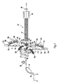
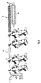
- FIG 1 is schematically a printing device according to the Invention shown.
- the printing device contains two Printing units 6, 8, which are constructed in the same way.
- the lower printing unit 6 is explained, its agreggate are designated by reference numerals with the addition a.
- the same Agreggate are also used in the upper printing unit 8, are there with corresponding reference numerals and referred to the letter b.
- the printing unit 6 has a photoconductor belt 10a, the endless of which The peripheral surface can be fully charged with a latent charge pattern is.
- the photoconductor belt 10a is rotated in Guided in the direction of arrow 11a past a transfer printing point 12a, to supply toner to a continuous paper web 15 transfer.
- a transfer roller 14a is a transfer printing corotron 16a associated with the toner particles on the photoconductor belt 10a by the action of an electrostatic Force field accumulates on the paper web 15, so that a still smearable toner image is formed on the paper web.
- the transfer printing corotron 16a is in the transport direction of the paper web 15 seen a conditioning corotron 18a, which the paper web 15 in a defined electrostatic initial state added.
- the transfer roller 14a Opposing the transfer roller 14a is a deflecting roller 20a arranged, which deflects the photoconductor 10a.
- the Photo conductor 10a is designed as an elongated loop, whose longitudinal axis is essentially vertical. This makes it possible to create the necessary ones Agreggate along this longitudinal axis on both sides of the photoconductor 10a, which makes it possible to arrange the two Transfer points 12a and 12b with a small lateral offset in Arrange the transport direction of the paper web 15.
- the length of the Photoconductor tape 10a is selected so that there is sufficient space for the mentioned Agreggate remains.
- the photoconductor band 10a opens multiple rollers (not specifically identified), among others guided the rollers 14a and 20a.
- a tension member 22a is switchable in two positions. In one position it is Photoconductor tape 10a tensioned. In the other position the reduced mechanical tension of the photoconductor belt 10a. In this position the photoconductor belt can be replaced or it maintenance work can be carried out.
- the deflecting roller 20a On the deflecting roller 20a is designed as a character generator 24a Exposure unit arranged, the light emitting Contains diodes and is also referred to as an LED exposure unit becomes.
- the character generator 24a generates on the photoconductor belt 10a shows a latent charge image with a charge distribution according to the characters or picture elements to be printed. Seen in the direction of rotation is after the character generator 24a a developer station 26a is provided, which is the charge image colored with toner. This toner image is, as mentioned, on the Transfer transfer point 12a to the underside of the paper web 15.
- the photoconductor belt 10a In the start and stop mode, the photoconductor belt 10a must be the paper web 15 are pivoted away.
- a pivoting device 28a is provided which holds the photoconductor belt 10a either in the dashed lines in Figure 1 drawn position or in the dashed line Holds position. In the position shown in dashed lines is the photoconductor belt 10a pivoted away from the paper web 15; a transfer of toner is excluded. It should be noted that the pivoting of the photoconductor belt 10a without change the length of the photoconductor tape takes place so that the electrophotographic Process, for example exposing the photoconductor tape, does not have to be interrupted.
- Both Agreggate have that Task that after printing at the transfer location 12a to remove existing toner from the photoconductor belt 10a in order to this for subsequent exposure and toner ingestion bring a defined initial state.
- a charging corotron 34a which a defined one on the surface of the photoconductor belt 10a State of charge generated. The process of charge imaging and the coloring with toner is known per se and must not explained in detail here.
- the upper printing unit 8 has the same structure as the explained printing unit 6. Its marked with the addition b Agreggate therefore do not need to be explained again become. Only the conditioning corotron should be mentioned 18b, which the paper web 15 after printing on both sides through the printing units 6, 8 in a largely neutral brings electrostatic condition.
- the paper web 15 is in the direction of the arrow P1 via a deflection roller 35 of a transverse alignment device 36 fed to the paper web 15 in the direction roughly aligned transversely to the transport direction P1. Subsequently the paper web 15 is guided past a vacuum brake 38, which sucks the paper web 15 with negative pressure, to keep the longitudinal tension in it at a defined value to be able to.
- the paper web 15 then passes through a side guiding device 40, which is an exact lateral guidance of the Paper web 15 for the subsequent transfer printing on the printing units 6, 8 controls. In terms of lateral guidance the rough alignment device 36 for rough alignment and the Lateral guide device 40 for fine lateral alignment the paper web 15.
- a pair of friction rollers 43 is used for the forward transport of the Paper web 15.
- the paper web 15 runs on a straight line Walk horizontally past the transfer locations 12a, 12b and will there in simplex printing operation through the upper printing unit 8 and printed in duplex printing mode by both printing units 6, 8.
- the printing unit 6 thus becomes inactive in simplex printing operation switched to the top of the paper web 15 the toner image to print.
- This has the advantage that an operator Check the top when setting up the print image can.
- simplex printing to switch the upper printing unit 8 inactive and the pressure to accomplish that under printing unit 6.
- An advantage of the chosen arrangement is that if one Printing unit, e.g. the printing unit 6, the other printing unit, e.g. the printing unit 8, maintain the simplex printing operation can.
- the paper web 15 provided with toner images arrives in a Fixing device 42 with an elongated, horizontal extending fixation 44.
- the fixing device 42 works the fixing device 42 with infrared radiation.
- it can also be used a fixing device Hot pressure fixation by means of two pressing against each other Rolling realized.
- they are double-sided toner images applied to the paper web 15 simultaneously fixed. It is essential that between the last transfer point 12b and passing through the fixation zone to none mechanical contact with the toner images on the paper web 15 is coming. This means that the paper web 15 in one tensioned state must be kept, what by the pair of transport rollers 48 is reached, which is the paper web 15 transported under tension.
- the fixing device 42 is a cooling device 46 downstream, which the heated Paper web 15 cools.
- the exemplary embodiment according to FIG. 1 can perform duplex printing at the same speed like a simplex printing operation. Because the two transfer points 12a and 12b are almost opposite each other or in one are arranged at a small lateral distance from one another the fit of the printed images produced is very high, i.e. optimal print quality is achieved.
- the paper web is transported 15 without intervention in an edge perforation of the paper web.
- a paper transport can also be used Intervention in an edge perforation of the paper web 15 take place.
- To the Paper drives are then used to drive the tractor by means of transport spikes in the edge holes of the paper web 15 intervention. In this way, the edge-precise guidance of the Paper web 15 secured and components such as transverse alignment device, Lateral guiding device, vacuum brake, suction table can be omitted.
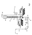
- a printing device is shown schematically, which essentially corresponds to that of Figure 1.
- the two printing units 6, 8 contain several Developer stations 50a, 50b, 50c, 50d.
- the paper web 15 at the transfer printing points 12a, 12b can each according to the number of developer stations used, in the present Case four developer stations 50a to 50d, several Toner images are collected one above the other on the paper web 15.
- the print speed works in this mode according to the required forward and backward movement back.
- Transfer rollers 14a, 14b are with each backward movement the paper web 15 to pivot away from her to blur avoid the not yet fixed toner images.
- Using the well-known process colors yellow, magenta, cyan and Black as a toner in the developer stations 50a to 50d can with appropriate process control, full-color printing in simplex printing or generated in duplex printing.
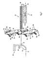
- FIG. 3 shows a further variant of the printing device according to the invention.
- Each pair of printing units 6a, 8a and 6b, 8b has essentially the structure shown in FIG. With the arrangement shown in Figure 3 is particular fast two-color duplex operation possible.
- a toner image with a first color is printed on.
- a second toner image on the paper web 15 applied by the developer station 52b.
- the Top of the paper web 15 is in an analogous manner by the Printing units 8a and 8b printed.
- the toner images on both sides the paper web 15 are in the single fixing device 42nd fixed together.
- FIG. 4 shows a further variant with pairs Printing units according to Figure 3.
- the pair of printing units with the Printing units 6b, 8b have four developer stations 50a to 50d equipped, as is also shown in Figure 2.
- the printing units 6a, 8a correspond to those of Figure 1.
- Die Arrangement according to Figure 4 can be advantageous for the alternate Duplex printing mode, the two-color duplex mode and one Multi-color duplex operation can be used. With a continuous Movement of the paper web 15 can by the first Printing couple 6a, 8a with the developer stations 52a, 52a Toner image of a first color can be applied on both sides. If the second pair of printing units 6b, 8b is switched to inactive, a single-color duplex printing operation is thus realized.
- Two-color duplex operation can be realized by using one of the Developer stations 50a to 50d a toner image with a corresponding Color on the respective photoconductor tape 10a, 10b applies.
- a multi-color duplex printing operation can be realized become.
- Repeated operation can be done accordingly the developer stations present in the printing units 6b, 8b 50a to 50d and toner colors a multi-color duplex printing company will be realized.
- Between the operating mode with continuous Printing operation (without repeating) and the repeating Printing operations can be done quickly without mechanical changes change.
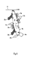
- FIG. 5 shows another example in which the paper web 15 for printing by the two printing units 6, 8 and the fixing device is moved in the vertical direction.
- the Printing units 6, 8 are constructed as in FIG. 2. This arrangement has the advantage that the paper web 15 between the transfer printing point of the last printing unit 8 and the pair of transport rollers 48 do not sag due to their own weight can. The risk of injury and blurring the printed image when moving along a long fusing line is avoided.
- the longitudinal axes of the Grinding the photoconductor tapes 10a, 10b of the printing units 6, 8 are arranged essentially horizontally in this case.
- FIG. 6 shows a printing device with a printing unit 54, which is constructed in the manner of the printing unit 6 according to FIG. 1. The same parts are labeled the same.
- the printing unit 54 contains a second loading corotron 35a, a second line generator 31a and one second development station 27a.
- the circulation of the photoconductor belt 10a is replaced by the charging corotron 34a, 20a and the character generator 24a after one from Océ Printing Systems GmbH developed a first latent charge pattern and then a first toner image through the developer station 26a generated.
- the second character generator 31a generates in conjunction with the charging corotron 35a on the developed first charge pattern by superimposing a second latent one Charge image developed by the developer station 27a becomes.
- the two developer stations 26a, 27a different toner colors, so there will be another one The first toner image on the photoconductor belt 10a superimposed.
- the resulting toner image is then at the transfer location transferred to the paper web 15.
- another charging corotron, another exposure unit and another developer station, preferably with one further toner color to be arranged along the photoconductor belt 10a, to take more than two toner images on the photoconductor belt overlay, which are then transferred together to the paper web 15 become.
- the printing unit 54 shown in FIG. 6 can be of various types Variants according to the principles shown in Figures 1 to 5 be used.
- 7 shows the printing unit 54 a similar printing unit 56 arranged opposite. The entire arrangement is essentially the same as that Figure 1 match. The same parts are again labeled the same.
- Paper web on a deflector 58 which is an air cushion generated, deflected virtually without contact and the cooling device 46 fed.
- the printing device shown in Figure 7 is a two-color duplex printing operation with high printing speed possible.
- FIG two pairs of printing units in the manner of printing pair 54, 56 are connected in series.
- Each printing unit 54a, 54b, 56a, 56b can repeat a two-tone toner image at a time without repeating apply one side of the paper web. Because of the arrangement with a short paper path between the first printing unit 54a and the last printing unit 56b a high registration accuracy is achieved.
- a four-color duplex printing operation can be realized. If the process colors are yellow, magenta, cyan and Black can be used as toner in the developer stations is full color printing with appropriate process control both sides of the paper web 15 possible without repeating must be printed.
- Figure 9 shows a variant with four similar printing units 54a, 54b, 54c, 54d, each according to the type shown in FIG shown printing unit are constructed.
- a turning device 60 arranged, which turns the paper web 15. With this Arrangement can also be a four-color duplex printing operation can be realized with high printing speed without that the paper web 15 must be repeated.
- the order 9 has the advantage that the overall height of the printing units 54a to 54d in a housing-accommodating printer is reduced.
- the turning device 60 is as Cross turner, which is on the bottom of the Paper web 15 through the printing units 54a, 54b printed toner image is not mechanically damaged.
Description
Die Erfindung betrifft eine elektrografische Druckeinrichtung, insbesondere einen Drucker oder einen Kopierer, mit mindestens zwei im wesentlichen gleichartigen Druckwerken mit je einer Umdruckstelle zwischen denen eine zu bedruckende Trägerbahn geführt ist. Ferner betrifft die Erfindung ein Verfahren zum Betreiben einer Druckeinrichtung.The invention relates to an electrographic printing device, especially a printer or a copier with at least two essentially identical printing units one transfer point between each one to be printed Carrier web is guided. The invention further relates to a Method for operating a printing device.
Bei einer herkömmlichen Druckeinrichtung wird auf einen Tonerbildträger mit Hilfe eines elektrografischen Verfahrens, z.B. durch Belichten eines Fotoleiters oder durch Magnetisieren einer magnetempfindlichen Schicht, ein latentes Bild aufgebracht. Gemäß der bildförmigen Verteilung der elektrischen Ladungen oder der magnetischen Pole lagert sich an dem latenten Bild Toner an. Auf ein Trägermaterial, im allgemeinen eine Papierbahn, wird dann der Toner an der Umdruckstelle übertragen. Das Tonerbild auf dem Tragermaterial wird später fixiert.In a conventional printing device, a toner image carrier is used with the help of an electrographic process, e.g. by exposing a photoconductor or by magnetizing a magnetically sensitive layer, a latent image is applied. According to the pictorial distribution of the electrical Charges or the magnetic poles are attached to the latent Image toner on. On a backing, in general a paper web, then the toner at the transfer location transfer. The toner image on the carrier material becomes later fixed.
In der modernen Drucktechnik wird gefordert, daß ein einziges Gerät das Trägermaterial auf beiden Seiten mit hoher Geschwindigkeit bedruckt. Diese Betriebsart wird allgemein als Duplex-Druck bezeichnet. Ferner wird die Betriebsart Spot-Colour-Druck oder Zweifarben-Druck gefordert, bei dem zweifarbig auf mindestens einer Seite gedruckt wird. Außerdem besteht der Bedarf nach einem Vollfarb-Druck mit den vier Prozeßfarben. Um beispielsweise die Betriebsart Duplex-Druck zu realisieren, ist es bekannt, die kontinuierliche Trägerbahn zunächst auf einer Seite zu bedrucken, dann die Trägerbahn zu wenden und mit demselben Druckwerk die zweite Seite zu bedrucken. Bei dieser Lösung ist eine Bahnwendeeinrichtung erforderlich. Der Transportweg der Trägerbahn durch den Drukker hindurch ist relativ lang und erfordert eine komplizierte und damit auch störanfällige Transportvorrichtung für das Trägermaterial. Modern printing technology requires that only one Applies the carrier material on both sides at high speed printed. This mode is commonly called Called duplex printing. Furthermore, the operating mode spot color printing or two-color printing, where two-color is required is printed on at least one page. Moreover there is a need for full-color printing with the four Process colors. For example, the duplex printing mode it is known to realize the continuous carrier web first to print on one side, then the carrier web and the second page with the same printing unit to print on. In this solution there is a web turning device required. The transport route of the carrier web through the printer through it is relatively long and requires a complicated one and thus also susceptible to malfunctioning transport device for the Support material.
Ein weiterer Nachteil des bekannten Druckers besteht darin, daß, wenn das Tonerbild auf der einen Seite der Trägerbahn noch nicht fixiert ist, es verwischt werden kann und somit die Druckqualität vermindert ist bzw. Ausschuß produziert wird. Um dies zu vermeiden, kann eine Zwischenfixierung des Tonerbildes erfolgen, wodurch jedoch der technische Aufwand groß wird. Außerdem muß die Trägerbahn nach dem Bedrucken auf der zweiten Seite ein zweites Mal den Fixierprozeß durchlaufen, wodurch sie thermisch hoch belastet wird, Schrumpfungsprobleme auftreten und die Paßgenauigkeit des Drucks verringert wird. Wegen des langen Transportweges zwischen der ersten Umdruckstelle für das erste Umdrucken eines Tonerbildes und der zweiten Umdruckstelle kann die Einhaltung einer hohen Paßgenauigkeit der Trägerbahn nur mit hohem technischen Aufwand gewährleistet werden.Another disadvantage of the known printer is that that if the toner image is on one side of the carrier web is not yet fixed, it can be blurred and therefore the print quality is reduced or rejects are produced becomes. To avoid this, an intermediate fixation of the Toner image done, but this means the technical effort gets big. In addition, the carrier web has to be printed on go through the fixing process a second time on the second side, as a result of which it is subjected to high thermal stress, shrinkage problems occur and the accuracy of the print is reduced becomes. Because of the long transport route between the first Transfer point for the first transfer printing of a toner image and the second transfer point can ensure compliance with a high Fitting accuracy of the carrier web only with great technical effort be guaranteed.
Die vorgenannten Probleme treten auch bei einem sogenannten "Twin-System" auf, bei dem zwei gleichartige Drucker in Reihe miteinander geschaltet werden, um unter Wenden der Trägerbahn einen zweiseitigen Druck, d.h. den Duplex-Druck, zu realisieren. Neben den hohen Kosten für zwei Drucker ist ferner nachteilig, daß eine große Stellfläche bereitgestellt werden muß und die Gerätesteuerung der beiden Drucker mit relativ hohem technischen Aufwand aufeinander abgestimmt werden muß.The aforementioned problems also occur with a so-called "Twin-System" with two identical printers in a row can be switched together to turn the carrier web two-sided printing, i.e. to realize duplex printing. In addition to the high cost of two printers, it is also disadvantageous that a large footprint must be provided and the device control of the two printers with a relatively high technical effort must be coordinated.
Aus der EP 0 629 931 A1 (Anmelder XEIKON) ist ein elektrostatischer Drucker bekannt, bei dem eine Trägerbahn in vertikaler Richtung zwischen einer Vielzahl von Tonerbildträgern hindurchgeführt wird. Jeder Tonerbildträger hat eine ein Tonerbild erzeugende Einrichtung. Der Toner wird an je einer Umdruckstelle der Tonerbildträger auf die Trägerbahn übertragen. Durch beidseitige Anordnung von Tonerbildträgern längs der vertikal verlaufenden Trägerbahn ist ein Duplexdruck mit verschiedenen Tonerfarben möglich. Das bekannte Gerät hat einen komplexen Aufbau, eine komplizierte Trägermaterialführung und ist voluminös. From EP 0 629 931 A1 (applicant XEIKON) is an electrostatic Printer known in which a carrier web in vertical Direction between a variety of toner image carriers is passed through. Each toner image carrier has a toner image generating device. The toner is on one Transfer the transfer point of the toner image carrier to the carrier web. By arranging toner image carriers on both sides lengthways the vertically running carrier web is a duplex print with different toner colors possible. The well-known device has a complex structure, a complicated substrate management and is voluminous.
Aus der EP 0 433 444 B1 (Anmelderin: Eastman Kodak Company) ist ein Drucker bekannt, bei dem längs eines Fotoleiterbandes als Tonerbildträger mehrere Entwicklerstationen angeordnet sind. Jede Entwicklerstation kann das von einer Belichtungsstation erzeugte Ladungsbild mit Toner einer vorbestimmten Farbe versehen. Das auf dem Fotoleiterband erzeugte Tonerbild wird dann an einer einzigen Umdruckstelle auf das Trägermaterial übertragen. Auch dieser Drucker ist technisch aufwendig und kann in den verschiedenen Betriebsarten nur geringe Druckgeschwindigkeiten realisieren.From EP 0 433 444 B1 (applicant: Eastman Kodak Company) a printer is known in which along a photoconductor belt several developer stations arranged as a toner image carrier are. Every developer station can do this from an exposure station generated charge image with toner of a predetermined Color. The toner image created on the photoconductor belt is then at a single transfer location on the carrier material transfer. This printer is also technically complex and can only be slight in the different operating modes Realize printing speeds.
Aus der EP-A-0 629 924 ist eine ähnliche Druckeinrichtung wie in EP-A-0 629 931
beschrieben bekannt, welche die Merkmale des Oberbegriffs von Patentanspruch 1 enthält. Als Fotoleiter bzw. Tonerträger
kann auch ein Fotoleiterband verwendet werden.From EP-A-0 629 924 is a similar printing device as in EP-A-0 629 931
described known, which contains the features of the preamble of
Aus der EP-A-0 742 496 ist eine elektrografische Druckeinrichtung, insbesondere Drucker oder Kopierer, mit mindestens zwei im wesentlichen gleichartigen Druckwerken bekannt. Eine Trägerbahn wird zwischen den einander gegenüberliegend angeordneten Druckwerken durchgeführt und bedruckt. Die Druckwerke ermöglichen einen Vielfarbendruck.EP-A-0 742 496 discloses an electrographic printing device, especially printer or copier, with at least two essentially identical printing units are known. A Carrier web is arranged between the opposite one another Printing units carried out and printed. The printing units enable multi-color printing.
Aus Patent Abstracts of Japan, Band 15, Nr. 20 (P1154), 17.
Januar 1991; Pub. Nr.: JP-A-02264276, ist eine Druckeinrichtung
bekannt, bei der ein repetierender Betrieb realisiert
ist. Diese Druckeinrichtung bedruckt Einzelblätter auf nur
einer Seite. Die Einzelblätter werden im repetierenden Betrieb
hin- und herbewegt. Bei der einen Bewegungsrichtung
wird das Fotoleiterband sowohl mit einer Entwicklungseinheit
als auch mit den Einzelblättern in Kontakt gebracht. Beim Bewegen
der Einzelblätter in die andere Richtung wird das Fotoleiterband
sowohl vcn den Einzelblättern als auch von der
Entwicklungseinheit wegbewegt. From Patent Abstracts of Japan,
Es ist Aufgabe der Erfindung, eine elektrografische Druckeinrichtung anzugeben, die mit hoher Druckgeschwindigkeit arbeitet und einen kompakten Aufbau hat. Ferner soll eine hohe Flexibilität im Hinblick auf verschiedene Druckbetriebsarten erreicht werden.It is an object of the invention to provide an electrographic printing device specify that works at high printing speed and has a compact structure. Furthermore, a high Flexibility with regard to different printing modes can be achieved.
Dies wird durch eine Vorrichtung gemäss dem unabhängigen Vorrichtungsanspruch 1 und durch eine Verfahrens gemäss dem unabhängigen Verfahrensanspruch 23 erreicht.This is achieved by a device according to
Gemäß der Erfindung wird eine elektrografische Druckeinrichtung mit mindestens zwei im wesentlichen gleichartigen Druckwerken mit je einer Umdruckstelle angegeben, zwischen denen eine zu bedruckende Trägerbahn geführt ist. Die Umdruckstellen sind mit geringem seitlichen Versatz in Bewegungsrichtung der Trägerbahn einander gegenüberliegend angeordnet. Jedes Druckwerk hat ein Tonerträgerband, auf dessen endloser Umfangsfläche gemäß einer bildförmigen Verteilung Toner auftragbar ist, der an der jeweiligen Umdruckstelle auf die ihr gegenüberliegende Fläche der Trägerbahn übertragbar ist.According to the invention, an electrographic printing device with at least two essentially identical printing units each with a transfer location between which a carrier web to be printed is guided. The transfer points are with little lateral offset in the direction of movement the carrier web arranged opposite each other. each Printing unit has a toner carrier tape on its endless peripheral surface toner can be applied according to an image-shaped distribution is the one at the respective transfer printing station opposite surface of the carrier web is transferable.
Bei der Erfindung wird Toner auf ein Tonerträgerband übertragen, welches auf seiner endlosen Umfangsfläche ein latentes Bild trägt. Als Tonerträgerband kann jedes Band verwendet werden, welches auf magnetischem oder elektrischem Wege ein latentes Ladungsbild erzeugen kann. Vorzugsweise wird ein Fotoleiterband verwendet, welches durch Belichten ein elektrisches Ladungsbild erzeugt, wobei sich Tonerteilchen beim Entwickeln entsprechend der Ladungsverteilung auf der Umfangsfläche des Fotoleiterbandes anlagern. Mithilfe des Tonerträgerbandes kann eine langgestreckte Schleife erzeugt werden, welche es ermöglicht, daß die für das Erzeugen eines Tonerbildes erforderlichen Agreggate entlang der Länge des Tonerträgerbandes verteilt angeordnet werden können. Auf diese Weise ist eine kompakte Anordnung zweier Tonerträgerbahnen möglich, deren Umdruckstellen einander gegenüberliegend angeordnet sind, so daß ein einziger Drucker zwei Druckwerke enthalten kann, ohne daß ein voluminöses Gerät entsteht. Durch die Verwendung von Tonerträgerbahnen in den Druckwerken ist es ferner möglich, die beiden Umdruckstellen mit geringem seitlichen Versatz zueinander einander gegenüberliegend anzuordnen. Vorzugsweise ist der seitliche Abstand der beiden Umdruckstellen voneinander nur durch die Abmessungen der zwischen den Umdruckstellen anzuordnenden Umdruckkoronavorrichtung begrenzt. Auf diese Weise rücken die beiden Umdruckstellen nahe zueinander, so daß der Transportweg für die Trägerbahn zwischen diesen Umdruckstellen minimal ist. Dadurch wird eine hohe Paßgenauigkeit für die von beiden Druckwerken erzeugten Druckbilder erreicht.In the invention, toner is transferred to a toner carrier belt which is a latent on its endless circumferential surface Image carries. Any tape can be used as the toner carrier tape be, which is a magnetic or electrical way can generate latent charge image. Preferably a Photoconductor tape used, which is an electrical by exposure Charge image is generated, with toner particles when Develop according to the charge distribution on the peripheral surface attach the photoconductor tape. Using the toner carrier tape can create an elongated loop be, which enables the for the creation of a Toner image required along the length of the Agreggate Toner carrier tape can be arranged distributed. On this is a compact arrangement of two toner carrier webs possible, the transfer points opposite each other are arranged so that a single printer can contain two printing units without a bulky device arises. By using toner carrier webs in the printing units, it is also possible to use the two transfer printing points with a small lateral offset to each other to be arranged opposite one another. Preferably the side one Distance between the two transfer printing points only by the Dimensions of the to be arranged between the transfer printing points Transfer corona device limited. In this way they move two transfer points close to each other, so that the transport route minimal for the carrier web between these transfer printing points is. This ensures a high accuracy of fit for both of them Printing units generated print images achieved.
Wenn bei der Erfindung beide Druckwerke im Druckbetrieb arbeiten, so kann mit hoher Geschwindigkeit die Betriebsart Duplex-Druck realisiert werden. Ein Wenden der Trägerbahn ist nicht erforderlich. Da beide Umdruckstellen im geringen Abstand voneinander angeordnet sind, wird die Paßgenauigkeit der Druckbilder durch Schrumpfungsprozesse, Änderung der Feuchtigkeit etc. nicht beeinflußt.If, in the invention, both printing units are operating in printing mode, the operating mode can be operated at high speed Duplex printing can be realized. The carrier web is turning not mandatory. Because both transfer points are close together are arranged from each other, the fit of the printed images due to shrinking processes, change of Moisture etc. not affected.
Die Trägerbahn wird auf einem geraden Wege zwischen den Umdruckstellen geführt. Die von den beiden Druckwerken aufgebrachten Tonerbilder werden durch keine Führungselemente mehr berührt, bis sie einen Fixierprozeß durchlaufen haben. Dadurch ist die Gefahr eines Verwischens der noch nicht fixierten Tonerbilder ausgeschlossen und es wird eine hohe Druckqualität erreicht. The carrier web is on a straight path between the transfer printing points guided. The applied by the two printing units Toner images are no longer by any guide elements touched until they have gone through a fixing process. Thereby is the danger of blurring those not yet fixed Toner images excluded and there will be high print quality reached.
Ein Ausführungsbeispiel der Erfindung ist dadurch gekennzeichnet, daß die Trägerbahn im wesentlichen waagrecht verläuft. Diese waagrechte Anordnung hat den Vorteil, daß eine Bedienperson zur Überprüfung des Druckbildes von oben auf die Trägerbahn schauen kann. Die Prüfperson nimmt hierbei eine natürliche und bequeme Haltung ein.An embodiment of the invention is characterized in that that the carrier web runs essentially horizontally. This horizontal arrangement has the advantage that a Operator to check the print image from above on the Carrier web can look. The examiner takes one natural and comfortable posture.
Bei der Erfindung enthält jedes Druckwerk eine Schwenkvorrichtung, durch die das Fotoleiterband vom Trägerband weggeschwenkt und an das Trägerband angeschwenkt werden kann. Durch diese Maßnahmen muß das Trägerband bei einem Start- und Stopp-Betrieb selbst nicht bewegt werden. Entsprechende technische Einrichtungen können somit entfallen. Beim Verschwenken des Fotoleiterbandes wird die Länge des Fotoleiterbandes nicht geändert. Dadurch wird die Gefahr von Verwischern im Druckbild reduziert. Im weggeschwenkten Zustand der Schwenkvorrichtung ist es außerdem möglich auf dem Fotoleiterband mehrere Tonerbilder aufzusammeln und diese später gemeinsam umzudrucken.In the invention, each printing unit contains a swivel device, through which the photoconductor belt is pivoted away from the carrier belt and can be pivoted to the carrier tape. Through these measures, the carrier tape at a start and Stop operation itself cannot be moved. Appropriate technical Facilities can thus be omitted. When swiveling of the photoconductor tape becomes the length of the photoconductor tape not changed. This will reduce the risk of blurring in the Print image reduced. In the swung-away state of the swivel device it is also possible on the photoconductor tape collect several toner images and collect them later transfer-print.
Gemäß einem Ausführungsbeispiel mit einem Fotoleiterband als Tonerbildträger ist die äußere Umfangsfläche des Fotoleiterbandes vollkommen mit einem latenten Ladungsbild aufladbar. Die Verwendung eines umlaufenden endlosen Fotoleiterbandes ist für Einzelblatt-Drucker an sich bekannt. Ein solches Fotoleiterband hat eine Nahtstelle, an welcher kein Ladungsbild erzeugt werden kann. Diese Nahtstelle wird in der Regel durch ein Indexloch gekennzeichnet und bei der Belichtung durch die Belichtungseinheit von der Gerätesteuerung berücksichtigt. Beim Zuführen von Einzelblättern wird dann sichergestellt, daß sich die Nahtstelle immer zwischen zwei Enden aufeinanderfolgender Einzelblätter befindet, so daß sich die Nahtstelle im Druckbild nicht bemerkbar macht. Bei der Verwendung von Bandmaterial als Trägermaterial ist nun gemäß dem Ausführungsbeispiel die Nahtstelle möglichst klein bzw. es ist keine Nahtstelle vorhanden. Das Fotoleiterband ist also vollkommen mit fotoaktivem Material zu beschichten, so daß es längs seiner Umfangsfläche vollkommen mit einem latenten Ladungsbild aufladbar ist. Auf diese Weise kann das Bandmaterial ohne Unterbrechung bedruckt werden - es entsteht keine Drucklücke.According to an embodiment with a photoconductor tape as The toner image carrier is the outer peripheral surface of the photoconductor belt fully rechargeable with a latent charge pattern. The use of a continuous endless photoconductor belt is known per se for single sheet printers. Such a photoconductor band has an interface at which no charge pattern can be generated. This interface is usually through marked an index hole and when exposed by the Exposure unit taken into account by the device control. When feeding single sheets, it is then ensured that that the seam is becoming more and more consecutive between two ends Single sheets are located so that the seam not noticeable in the printed image. When using of tape material as the carrier material is now according to the embodiment the seam is as small as possible or it is no interface available. So the photoconductor tape is perfect to coat with photoactive material so that it along its circumferential surface with a latent charge pattern is rechargeable. In this way, the tape material be printed without interruption - there is none Pressure gap.
Gemäß einem weiteren Ausführungsbeispiel enthält die ein Tonerbild erzeugende erste und/oder zweite Einrichtung jeweils mehrere Entwicklerstationen. Wenn diese Entwicklerstationen Toner mit unterschiedlichen Farben haben, ist ein Mehrfarbendruck möglich. Dieser Mehrfarbendruck kann im einfachen Fall ein Spot-Color-Druck oder bei entsprechender Prozeßführung ein Vollfarbendruck mit den Prozeßfarben Yellow, Magenta, Cyan und Black sein.According to a further exemplary embodiment, the contains a toner image generating first and / or second device each several developer stations. If these developer stations Having toners with different colors is multi-color printing possible. This multi-color printing can in the simple case a spot color print or with appropriate process control full-color printing with the process colors yellow, magenta, Be cyan and black.
Zum Aufbringen verschiedener Tonerbilder kann ein repetitierender Betrieb vorgesehen sein, bei dem das Trägermaterial an den Umdruckstellen wiederholt durch eine Vorwärtsbewegung und eine Rückwärtsbewegung vorbeigeführt wird. Bei jedem Vorbeiführen in Vorwärtsrichtung wird ein Tonerbild auf das Trägermaterial übertragen. Auf diese Weise können Tonerbilder unterschiedlicher Farbe, die von den verschiedenen Entwicklungsstationen eines Umfangsabschnitts auf dem Fotoleiterband erzeugt werden, auf dem Trägermaterial gesammelt und anschließend gemeinsam fixiert werden. Bei jeder Rückwärtsbewegung ist das Fotoleiterband von der Trägerbahn wegzuschwenken, um das aufgebrachte Tonerbild bzw. die aufgebrachten Tonerbilder nicht zu verwischen.A repetitive can be used to apply different toner images Operation can be provided in which the carrier material the transfer points repeated by a forward movement and a backward movement is made. With every passing in the forward direction, a toner image is placed on the carrier material transfer. In this way, toner images can be different Color from the various development stations a peripheral portion on the photoconductor belt generated, collected on the substrate and then fixed together. With every backward movement the photoconductor tape has to be swung away from the carrier web, around the applied toner image or images Don't blur toner images.
Gemäß einem weiteren Aspekt der Erfindung wird ein Verfahren zum Betreiben einer elektrografischen Druckeinrichtung gemäß Anspruch 23 angegeben. Im kontinuierlichen Betrieb ist ein schneller Umdruck mit mindestens einer Farbe möglich. Im repetierenden Betrieb ist ein verlangsamter Umdruck mit mehreren Farben möglich.According to a further aspect of the invention, a method for operating an electrographic printing device according to Claim 23 specified. In continuous operation is a Fast transfer printing with at least one color possible. In repetitive Operation is a slow down transfer with several Colors possible.
Ausführungsbeispiele der Erfindung werden im folgenden anhand der Zeichnung erläutert. Darin zeigt
Figur 1- schematisch die elektrografische Druckeinrichtung mit zwei einander gegenüberstehenden Druckwerken,
Figur 2- die
Anordnung nach Figur 1, wobei die Druckwerke mehrere Entwicklerstationen enthalten, - Figur 3
- eine Druckeinrichtung mit zwei Paaren von gleichartigen Druckwerken,
Figur 4- eine Druckeinrichtung, deren Paare von Druckwerken unterschiedlich sind,
- Figur 5
- eine Druckeinrichtung nach
Art der Figur 2 mit vertikal verlaufender Trägerbahn, - Figur 6
- schematisch eine Anordnung mit zwei Belichtungseinheiten und zwei Entwicklerstationen in einem Druckwerk,
- Figur 7
- die paarweise Anordnung von Druckwerken nach Figur 6 mit geneigter Längsachse,
Figur 8- eine Anordnung mit zwei Paaren von Druckwerken nach Figur 6, und
- Figur 9
- eine Anordnung mit vier Druckwerken nach Figur 6, wobei zwischen je zwei Druckwerken die Trägerbahn gewendet wird.
- Figure 1
- schematically the electrographic printing device with two opposing printing units,
- Figure 2
- the arrangement according to Figure 1, wherein the printing units contain several developer stations,
- Figure 3
- a printing device with two pairs of similar printing units,
- Figure 4
- a printing device whose pairs of printing units are different,
- Figure 5
- 2 a printing device of the type of FIG. 2 with a vertically running carrier web,
- Figure 6
- schematically an arrangement with two exposure units and two developer stations in a printing unit,
- Figure 7
- the paired arrangement of printing units according to Figure 6 with an inclined longitudinal axis,
- Figure 8
- an arrangement with two pairs of printing units according to Figure 6, and
- Figure 9
- an arrangement with four printing units according to Figure 6, wherein the carrier web is turned between two printing units.
In Figur 1 ist schematisch eine Druckeinrichtung nach der
Erfindung dargestellt. Die Druckeinrichtung enthält zwei
Druckwerke 6, 8, die gleichartig aufgebaut sind. Im folgenden
wird lediglich das untere Druckwerk 6 erläutert, deren Agreggate
durch Bezugszeichen mit dem Zusatz a bezeichnet sind.
Dieselben Agreggate werden auch beim oberen Druckwerk 8 verwendet,
sind dort jedoch mit entsprechenden Bezugszeichen und
dem Buchstaben b bezeichnet.In Figure 1 is schematically a printing device according to the
Invention shown. The printing device contains two
Das Druckwerk 6 hat ein Fotoleiterband 10a, dessen endlose
Umfangsfläche vollkommen mit einem latenten Ladungsbild aufladbar
ist. Das Fotoleiterband 10a wird unter Drehbewegung in
Richtung des Pfeils 11a an einer Umdruckstelle 12a vorbeigeführt,
um Toner auf eine kontinuierliche Papierbahn 15 zu
übertragen. Einer Übertragungswalze 14a ist ein Umdruck-Korotron
16a zugeordnet, welche die Tonerpartikel auf dem Fotoleiterband
10a durch die Wirkung eines elektrostatischen
Kraftfeldes auf der Papierbahn 15 anlagert, so daß ein noch
verwischbares Tonerbild auf der Papierbahn entsteht. Dem Umdruck-Korotron
16a ist in Transportrichtung der Papierbahn 15
gesehen ein Konditionier-Korotron 18a vorgeschaltet, welches
die Papierbahn 15 in einen definierten elektrostatischen Ausgangszustand
versetzt.The printing unit 6 has a photoconductor belt 10a, the endless of which
The peripheral surface can be fully charged with a latent charge pattern
is. The photoconductor belt 10a is rotated in
Guided in the direction of arrow 11a past a transfer printing point 12a,
to supply toner to a
Der Übertragungswalze 14a gegenüberliegend ist eine Umlenkwalze
20a angeordnet, die die Fotoleiterbahn 10a umlenkt. Die
Fotoleiterbahn 10a ist als eine langgestreckte Schleife ausgebildet,
deren Längsachse im wesentlichen vertikal verläuft.
Dadurch ist es möglich, die für die Erzeugung notwendigen
Agreggate entlang dieser Längsachse beidseitig der Fotoleiterbahn
10a anzuordnen, wodurch es möglich wird, die beiden
Umdruckstellen 12a und 12b mit geringem seitlichen Versatz in
Transportrichtung der Papierbahn 15 anzuordnen. Die Länge des
Fotoleiterbandes 10a ist so gewählt, daß ausreichend Raum für
die genannten Agreggate verbleibt.Opposing the transfer roller 14a is a deflecting roller
20a arranged, which deflects the photoconductor 10a. The
Photo conductor 10a is designed as an elongated loop,
whose longitudinal axis is essentially vertical.
This makes it possible to create the necessary ones
Agreggate along this longitudinal axis on both sides of the photoconductor
10a, which makes it possible to arrange the two
Das Fotoleiterband 10a wird wie in Figur 1 zu sehen ist, auf
mehreren Walzen (nicht im einzelnen bezeichnet), unter anderem
den Walzen 14a und 20a geführt. Ein Spannelement 22a ist
in zwei Stellungen schaltbar. In der einen Stellung ist das
Fotoleiterband 10a gespannt. In der anderen Stellung wird die
mechanische Spannung des Fotoleiterbandes 10a verringert. In
dieser Stellung kann das Fotoleiterband ausgetauscht oder es
können Wartungsarbeiten vorgenommen werden.As can be seen in FIG. 1, the photoconductor band 10a opens
multiple rollers (not specifically identified), among others
guided the rollers 14a and 20a. A
An der Umlenkwalze 20a ist eine als Zeichengenerator 24a ausgebildete
Belichtungseinheit angeordnet, die lichtemittierende
Dioden enthält und auch als LED-Belichtungseinheit bezeichnet
wird. Der Zeichengenerator 24a erzeugt auf dem Fotoleiterband
10a ein latentes Ladungsbild mit einer Ladungsverteilung
gemäß den zu druckenden Zeichen oder Bildelementen.
In Drehrichtung gesehen ist nach dem Zeichengenerator 24a
eine Entwicklerstation 26a vorgesehen, die das Ladungsbild
mit Toner einfärbt. Dieses Tonerbild wird wie erwähnt an der
Umdruckstelle 12a auf die Unterseite der Papierbahn 15 übertragen.On the deflecting roller 20a is designed as a character generator 24a
Exposure unit arranged, the light emitting
Contains diodes and is also referred to as an LED exposure unit
becomes. The character generator 24a generates on the photoconductor belt
10a shows a latent charge image with a charge distribution
according to the characters or picture elements to be printed.
Seen in the direction of rotation is after the character generator 24a
a
Im Start- und Stopp-Betrieb muß das Fotoleiterband 10a von
der Papierbahn 15 weggeschwenkt werden. Zu diesem Zweck ist
eine Schwenkvorrichtung 28a vorgesehen, die das Fotoleiterband
10a entweder in der in Figur 1 mit ausgezogenen Strichen
gezeichneten Stellung oder in der gestrichelt gezeichneten
Stellung hält. In der gestrichelt gezeichneten Stellung ist
das Fotoleiterband 10a von der Papierbahn 15 weggeschwenkt;
ein Übertragen von Toner ist ausgeschlossen. Zu beachten ist,
daß das Verschwenken des Fotoleiterbandes 10a ohne Änderung
der Länge des Fotoleiterbandes erfolgt, so daß der elektrofotografische
Prozeß, beispielsweise das Belichten des Fotoleiterbandes,
nicht unterbrochen werden muß. Hierzu dient ebenfalls
das Spannelement 22a, welches abhängig von der Schwenkstellung
der Schwenkvorrichtung 28a in zwei Stellungen verstellbar
ist. In jeder dieser Stellungen wird das Fotoleiterband
10a unter Spannung gehalten. Ferner ist darauf hinzuweisen,
daß in der von der Papierbahn 15 weggeschwenkten Stellung
der Schwenkvorrichtung 28a es möglich ist, mehrere Tonerbilder
auf dem Fotoleiterband 10a zu sammeln, um die dann
überlagerten Tonerbilder umzudrucken. Diese Betriebsart wird
weiter unten noch erläutert. In the start and stop mode, the photoconductor belt 10a must be
the
In Drehrichtung des Fotoleiterbandes 10a gesehen ist nach dem
Umdruck-Korotron 16a ein Reinigungs-Korotron 30a und eine
Reinigungsstation 32a angeordnet. Beide Agreggate haben die
Aufgabe, den nach dem Drucken an der Umdruckstelle 12a noch
vorhandenen Toner vom Fotoleiterband 10a zu entfernen, um
dieses für die nachfolgende Belichtung und Toneraufnahme in
einen definierten Ausgangszustand zu bringen. Vor dem Zeichengenerator
24a ist ein Lade-Korotron 34a angeordnet, welche
auf der Oberfläche des Fotoleiterbandes 10a einen definierten
Ladezustand erzeugt. Der Prozeß der Ladungsbilderzeugung
und der Einfärbung mit Toner ist an sich bekannt und muß
hier nicht im einzelnen erläutert werden.Seen in the direction of rotation of the photoconductor belt 10a after
Transfer corotron 16a, a
Wie erwähnt hat das obere Druckwerk 8 denselben Aufbau wie
das erläuterte Druckwerk 6. Seine mit dem Zusatz b gekennzeichneten
Agreggate müssen daher nicht nochmals erläutert
werden. Zu erwähnen ist lediglich das Konditionier-Korotron
18b, welches die Papierbahn 15 nach dem beiderseitigen Bedrucken
durch die Druckwerke 6, 8 in einen weitgehend neutralen
elektrostatischen Zustand bringt.As mentioned, the
Im folgenden wird der Transport der Papierbahn 15 durch die
Druckeinrichtung beschrieben. Die Papierbahn 15 wird in Richtung
des Pfeils P1 über eine Umlenkrolle 35 einer Querausrichtvorrichtung
36 zugeführt, die die Papierbahn 15 in Richtung
quer zur Transportrichtung P1 grob ausrichtet. Anschließend
wird die Papierbahn 15 an einer Unterdruckbremse 38 vorbeigeführt,
welche die Papierbahn 15 mit Unterdruck ansaugt,
um die Längsspannung in ihr auf einem definierten Wert halten
zu können. Die Papierbahn 15 durchläuft dann eine Seitenführungsvorrichtung
40, welche eine genaue seitliche Führung der
Papierbahn 15 für den nachfolgenden Umdruck an den Druckwerken
6, 8 steuert. In bezug auf die seitliche Führung dient
die Querausrichtvorrichtung 36 zum groben Ausrichten und die
Seitenführungsvorrichtung 40 zum feinen seitlichen Ausrichten
der Papierbahn 15. In the following, the transport of the
Ein Friktionswalzenpaar 43 dient zum Vorwärtstransport der
Papierbahn 15. Die Papierbahn 15 läuft auf einem geradlinigen
Weg horizontal an den Umdruckstellen 12a, 12b vorbei und wird
dort im Simplex-Druckbetrieb durch das obere Druckwerk 8 und
im Duplex-Druckbetrieb durch beide Druckwerke 6, 8 bedruckt.
Im Simplex-Druckbetrieb wird also das Druckwerk 6 inaktiv
geschaltet, um auf die Oberseite der Papierbahn 15 das Tonerbild
zu drucken. Dies hat den Vorteil, daß eine Bedienperson
beim Einrichten des Druckbildes die Oberseite kontrollieren
kann. Es ist jedoch auch denkbar, für den Simplex-Druckbetrieb
das obere Druckwerk 8 inaktiv zu schalten und den Druck
durch das unter Druckwerk 6 zu bewerkstelligen.A pair of
Ein Vorteil der gewählten Anordnung ist, daß bei Ausfall eines
Druckwerks, z.B. des Druckwerks 6, das andere Druckwerk,
z.B. das Druckwerk 8, den Simplex-Druckbetrieb aufrechterhalten
kann.An advantage of the chosen arrangement is that if one
Printing unit, e.g. the printing unit 6, the other printing unit,
e.g. the
Die mit Tonerbilder versehende Papierbahn 15 gelangt in eine
Fixiervorrichtung 42 mit einer langgestreckten, horizontal
verlaufenden Fixierstrecke 44. Im vorliegenden Fall arbeitet
die Fixiervorrichtung 42 mit Infrarotstrahlung. Es kann jedoch
auch eine Fixiervorrichtung eingesetzt werden, die eine
Heißdruck-Fixierung mittels zweier gegeneinander drückender
Walzen realisiert. Im Duplex-Druckbetrieb werden die beidseitig
auf die Papierbahn 15 aufgebrachten Tonerbilder gleichzeitig
fixiert. Wesentlich ist, daß zwischen der letzten Umdruckstelle
12b und dem Durchlaufen der Fixierzone es zu keinem
mechanischen Kontakt mit den Tonerbildern auf der Papierbahn
15 kommt. Dies bedeutet, daß die Papierbahn 15 in einem
gespannten Zustand gehalten werden muß, was durch das Transportwalzenpaar
48 erreicht wird, welche die Papierbahn 15
unter Spannung transportiert. Der Fixiervorrichtung 42 ist
eine Kühlvorrichtung 46 nachgeschaltet, welche die aufgeheizte
Papierbahn 15 abkühlt. The
Wie dem Ausführungsbeispiel nach Figur 1 zu entnehmen ist,
kann ein Duplex-Druckbetrieb mit derselben Geschwindigkeit
wie ein Simplex-Druckbetrieb erfolgen. Da die beiden Umdruckstellen
12a und 12b sich nahezu gegenüberstehen bzw. in einem
geringen seitlichen Abstand voneinander angeordnet sind, ist
die Paßgenauigkeit der erzeugten Druckbilder sehr hoch, d.h.
es wird eine optimale Druckqualität erreicht.As can be seen from the exemplary embodiment according to FIG. 1,
can perform duplex printing at the same speed
like a simplex printing operation. Because the two
Beim Beispiel nach Figur 1 erfolgt der Transport der Papierbahn
15 ohne Eingriff in eine Randlochung der Papierbahn.
Selbstverständlich kann aber auch ein Papiertransport mit
Eingriff in eine Randlochung der Papierbahn 15 erfolgen. Zum
Papiertransport werden dann Traktorantriebe eingesetzt, die
mittels Transportstacheln in die Randlöcher der Papierbahn 15
eingreifen. Auf diese Weise ist die randgenaue Führung der
Papierbahn 15 gesichert und Komponenten wie Querausrichtvorrichtung,
Seitenführungsvorrichtung, Unterdruckbremse, Saugtisch
können entfallen.In the example according to FIG. 1, the paper web is transported
15 without intervention in an edge perforation of the paper web.
Of course, a paper transport can also be used
Intervention in an edge perforation of the
Aufgrund des kurzen Papierwegs zwischen den beiden Umdruckstellen
12a und 12b ist eine hohe Paßgenauigkeit der aufzudruckenden
Tonerbilder gegeben. Somit kann eine Zwischenspeicherung
von Daten für die Zeichengeneratoren 24a und 24b entfallen.
Die Belichtung des Fotoleiterbandes 10a bzw. 10b erfolgt
lediglich zeitversetzt um eine Zeit, die sich aus der
Transportgeschwindigkeit und dem Papierweg zwischen den beiden
Umdruckstellen 12a und 12b ergibt.Because of the short paper path between the two
In Figur 2 ist eine Druckeinrichtung schematisch dargestellt,
die in wesentlichen Teilen mit der nach Figur 1 übereinstimmt.
Die beiden Druckwerke 6, 8 enthalten jedoch mehrere
Entwicklerstationen 50a, 50b, 50c, 50d. In einem repetierenden
Betrieb, d.h. mit Vorwärtsbewegung und Rückwärtsbewegung
der Papierbahn 15 an den Umdruckstellen 12a, 12b können je
nach Anzahl der verwendeten Entwicklerstationen, im vorliegenden
Fall vier Entwicklerstationen 50a bis 50d, mehrere
Tonerbilder übereinander auf der Papierbahn 15 gesammelt werden.
Die Druckgeschwindigkeit geht bei dieser Betriebsart
entsprechend der erforderlichen Vorwärts- und Rückwärtsbewegung
zurück. Die Fixierung aller überlagerten Tonerbilder
erfolgt gemeinsam in der einzigen Fixiervorrichtung 42. Die
Übertragungswalzen 14a, 14b sind bei jeder Rückwärtsbewegung
der Papierbahn 15 von ihr wegzuschwenken, um ein Verwischen
der noch nicht fixierten Tonerbilder zu vermeiden. Bei Verwendung
der bekannten Prozeßfarben Yellow, Magenta, Cyan und
Black als Toner in den Entwicklerstationen 50a bis 50d kann
bei entsprechender Prozeßführung ein Vollfarb-Druck im Simplex-Druckbetrieb
oder im Duplex-Druckbetrieb erzeugt werden.In Figure 2, a printing device is shown schematically,
which essentially corresponds to that of Figure 1.
However, the two
Figur 3 zeigt eine weitere Variante der Druckeinrichtung nach
der Erfindung. Es sind zwei Paare von Druckwerken 6a, 8a und
6b, 8b in Reihe geschaltet. Jedes Paar von Druckwerken 6a, 8a
und 6b, 8b hat im wesentlichen den in Figur 1 gezeigten Aufbau.
Mit der in Figur 3 gezeigten Anordnung ist insbesondere
der schnelle Zweifarben-Duplexbetrieb möglich. Hierzu wird
auf der Unterseite durch das Druckwerk 6a von der Entwicklerstation
52a ein Tonerbild mit einer ersten Farbe aufgedruckt.
Anschließend wird durch das untere Druckwerk 6b des zweiten
Paars von Druckwerken ein zweites Tonerbild auf die Papierbahn
15 durch die Entwicklerstation 52b aufgebracht. Die
Oberseite der Papierbahn 15 wird in analoger Weise durch die
Druckwerke 8a und 8b bedruckt. Die Tonerbilder beider Seiten
der Papierbahn 15 werden in der einzigen Fixiervorrichtung 42
gemeinsam fixiert.FIG. 3 shows a further variant of the printing device according to
the invention. There are two pairs of
Figur 4 zeigt eine weitere Variante mit paarweise angeordneten
Druckwerken nach Figur 3. Das Druckwerkpaar mit den
Druckwerken 6b, 8b sind mit vier Entwicklerstationen 50a bis
50d ausgerüstet, wie dies auch in Figur 2 dargestellt ist.
Die Druckwerke 6a, 8a entsprechen denen nach Figur 1. Die
Anordnung nach Figur 4 kann vorteilhaft für den wechselweisen
Duplex-Druckbetrieb, dem Zweifarben-Duplexbetrieb und einem
Mehrfarben-Duplexbetrieb eingesetzt werden. Bei einer kontinuierlichen
Bewegung der Papierbahn 15 kann durch das erste
Druckwerkpaar 6a, 8a mit den Entwicklerstationen 52a, 52a ein
Tonerbild einer ersten Farbe beidseitig aufgebracht werden.
Wenn das zweite Druckwerkpaar 6b, 8b inaktiv geschaltet ist,
so wird ein Einfarben-Duplex-Druckbetrieb realisiert. Wenn
das Druckwerkpaar 6b, 8b aktiv geschaltet ist, so kann bei
schnellem kontinuierlichen Durchlauf der Papierbahn 15 ein
Zweifarben-Duplexbetrieb realisiert werden, indem eine der
Entwicklerstationen 50a bis 50d ein Tonerbild mit einer entsprechenden
Farbe auf das jeweilige Fotoleiterband 10a, 10b
aufbringt. Mit verschiedenen Tonerfarben der Druckwerke 6a,
8a und 6b, 8b, kann ein Mehrfarben-Duplex-Druckbetrieb realisiert
werden. Bei repetierendem Betrieb können entsprechend
der in den Druckwerken 6b, 8b vorhandenen Entwicklerstationen
50a bis 50d und Tonerfarben ein Mehrfarben-Duplex-Druckbetrieb
realisiert werden. Zwischen der Betriebsart mit kontinuierlichem
Druckbetrieb (ohne repetieren) und dem repetierenden
Druckbetrieb kann rasch, ohne mechanische Umstellungen
gewechselt werden.FIG. 4 shows a further variant with pairs
Printing units according to Figure 3. The pair of printing units with the
Figur 5 zeigt ein weiteres Beispiel, bei dem die Papierbahn
15 zum Bedrucken durch die beiden Druckwerke 6, 8 und durch
die Fixiervorrichtung in vertikaler Richtung bewegt wird. Die
Druckwerke 6, 8 sind wie nach Figur 2 aufgebaut. Diese Anordnung
hat den Vorteil, daß die Papierbahn 15 zwischen der Umdruckstelle
des letzten Druckwerks 8 und dem Transportwalzenpaar
48 aufgrund ihres Eigengewichtes nicht nach unten durchhängen
kann. Die Gefahr der Verletzung und des Verwischens
des Druckbildes bei der Beförderung entlang einer langen Fixierstrecke
wird dadurch vermieden. Die Längsachsen der
Schleifen der Fotoleiterbänder 10a, 10b der Druckwerke 6, 8
sind in diesem Fall im wesentlichen waagerecht angeordnet.Figure 5 shows another example in which the
Figur 6 zeigt eine Druckeinrichtung mit einem Druckwerk 54,
welches nach Art des Druckwerks 6 nach Figur 1 aufgebaut ist.
Gleiche Teile sind gleich bezeichnet. Zusätzlich zum Druckwerk
nach Figur 6 enthält das Druckwerk 54 ein zweites Lade-Korotron
35a, einen zweiten Zeilengenerator 31a und eine
zweite Entwicklungsstation 27a. Beim Umlauf des Fotoleiterbandes
10a wird durch das Lade-Korotron 34a, 20a und den Zeichengenerator
24a nach einem von Océ Printing Systems GmbH
entwickelten Verfahren ein erstes latentes Ladungsbild und
dann durch die Entwicklerstation 26a ein erstes Tonerbild
erzeugt. Anschließend erzeugt der zweite Zeichengenerator 31a
in Verbindung mit dem Lade-Korotron 35a auf dem entwickelten
ersten Ladungsbild durch Uberlagerung ein zweites latentes
Ladungsbild, das durch die Entwicklerstation 27a entwickelt
wird. Vorzugsweise haben die beiden Entwicklerstationen 26a,
27a unterschiedliche Tonerfarben, Es wird also ein weiteres
Tcnerbild dem ersten Tonerbild auf dem Fotoleiterband 10a
überlagert. Das resultierende Tonerbild wird dann an der Umdruckstelle
auf die Papierbahn 15 übertragen. Auf diese Weise
kann mit hoher Druckgeschwindigkeit an der Umdruckstelle ein
zweifarbiges Tonerbild gedruckt werden. Es ist auch möglich,
ein weiteres Lade-Korotron, eine weitere Belichtungseinheit
und eine weitere Entwicklerstation, vorzugsweise mit einer
weiteren Tonerfarbe, entlang dem Fotoleiterband 10a anzuordnen,
um auf dem Fotoleiterband mehr als zwei Tonerbilder zu
überlagern, die dann gemeinsam auf die Papierbahn 15 übertragen
werden.FIG. 6 shows a printing device with a
Das in Figur 6 gezeigte Druckwerk 54 kann in verschiedenen
Varianten gemäß den in den Figuren 1 bis 5 gezeigten Prinzipien
eingesetzt werden. Z.B. in Figur 7 ist dem Druckwerk 54
ein gleichartiges Druckwerk 56 gegenüberliegend angeordnet.
Die gesamte Anordnung stimmt im wesentlichen mit der nach
Figur 1 überein. Gleiche Teile sind wiederum gleich bezeichnet.
Nach dem Durchlaufen der Fixiervorrichtung 42 wird die
Papierbahn auf einer Umlenkeinrichtung 58, die ein Luftpolster
erzeugt, quasi berührungsfrei umgelenkt und der Kühlvorrichtung
46 zugeführt. Mit der in Figur 7 gezeigten Druckeinrichtung
ist mit hoher Druckgeschwindigkeit ein Zweifarben-Duplex-Druckbetrieb
möglich. The
In Figur 8 ist eine weitere Variante dargestellt, bei dem
zwei Paare von Druckwerken nach Art des Druckwerkpaars 54, 56
hintereinandergeschaltet sind. Jedes Druckwerk 54a, 54b, 56a,
56b kann ohne Repetieren ein zweifarbiges Tonerbild auf je
eine Seite der Papierbahn aufbringen. Aufgrund der Anordnung
mit kurzem Papierweg zwischen dem ersten Druckwerk 54a und
dem letzten Druckwerk 56b wird eine hohe Paßgenauigkeit erreicht.
Es läßt sich ein Vierfarben-Duplex-Druckbetrieb realisieren.
Wenn die Prozeßfarben Yellow, Magenta, Cyan und
Black als Toner in den Entwicklerstationen verwendet werden,
ist bei entsprechender Prozeßführung ein Vollfarb-Druck auf
beiden Seiten der Papierbahn 15 möglich, ohne daß repetierend
gedruckt werden muß.A further variant is shown in FIG
two pairs of printing units in the manner of
Figur 9 zeigt eine Variante mit vier gleichartigen Druckwerken
54a, 54b, 54c, 54d, die jeweils nach Art des in Figur 6
gezeigten Druckwerks aufgebaut sind. Zwischen den Druckwerken
54a, 54b und den Druckwerken 54c, 54d ist eine Wendeeinrichtung
60 angeordnet, welche die Papierbahn 15 wendet. Mit dieser
Anordnung kann ebenfalls ein Vierfarben-Duplex-Druckbetrieb
mit hoher Druckgeschwindigkeit realisiert werden, ohne
daß die Papierbahn 15 repetiert werden muß. Die Anordnung
nach Figur 9 hat den Vorteil, daß die Bauhöhe des die Druckwerke
54a bis 54d in einem Gehäuse aufnehmenden Druckers erheblich
reduziert wird. Die Wendeeinrichtung 60 ist als
Kreuzwender ausgeführt, bei der das auf die Unterseite der
Papierbahn 15 durch die Druckwerke 54a, 54b gedruckte Tonerbild
mechanisch nicht beschädigt wird. Figure 9 shows a variant with four
- 6,86.8
- Druckwerkprinting unit
- 10a, 10b10a, 10b
- FotoleiterbahnPhotoconductor web
- 12a, 12b12a, 12b
- Umdruckstelletransfer printing
- 11a, 11b11a, 11b
- DrehrichtungspfeilDirection arrow
- 14a, 14b14a, 14b
- Übertragungswalzetransfer roller
- 16a, 16b16a, 16b
- Umdruck-KorotronTransfer printing corotron
- 18a, 18b18a, 18b
- Konditionier-KorotronConditioning corotron
- 20a, 20b20a, 20b
- Umlenkwalzedeflecting
- 22a, 22b22a, 22b
- Spannelementclamping element
- 24a, 24b24a, 24b
- Zeichengeneratorcharacter generator
- 26a, 26b26a, 26b
- Entwicklerstationdeveloper station
- 27a, 27b27a, 27b
- Entwicklerstationdeveloper station
- 28a, 28b28a, 28b
- Schwenkvorrichtungswivel device
- 30a, 30b30a, 30b
- Reinigungs-KorotronCleaning corotron
- 32a, 32b32a, 32b
- Reinigungsstationcleaning station
- 34a, 34b34a, 34b
- Lade-KorotronCharging corotron
- 35a, 35b35a, 35b
- Lade-KorotronCharging corotron
- 3636
- Querausrichtvorrichtunglateral alignment
- 3838
- UnterdruckbremseVacuum brake
- 4040
- SeitenführungsvorrichtungLateral guide device
- 4242
- Fixiervorrichtungfixing
- 4343
- FriktionswalzenpaarFriktionswalzenpaar
- 4444
- Fixierstreckefixing path
- 4646
- Kühlvorrichtungcooler
- 4848
- TransportwalzenpaarTransport roller pair
-
50a, 50b
50c, 50d50a,
50b - Entwicklerstationdeveloper station
- 52a, 52b52a, 52b
- Entwicklerstationdeveloper station
- 54, 5654, 56
- Druckwerkprinting unit
- 5858
- Umlenkvorrichtungdeflecting
- 6060
- Wendeeinrichtungturning device
- P1P1
- TransportrichtungspfeilTransport direction arrow
Claims (25)
- Electrographic printer device, particularly printer or copier,characterized in that each printing unit (6, 8) contains a swivel mechanism (28a, 28b) with which the toner carrier band (10a, 10b) can be swivelled away from the carrier band and can be swivelled against the carrier band (15) only in the region of the transfer printing location, whereby a tensioning element (22a, 22b) holds the toner carrier band (10a, 10b) tensed and the swivelling ensues without changing the length of the toner carrier band (10a, 10b).comprising at least two essentially identical printing units (6, 8) each having a respective transfer printing location (12a, 12b) between which a carrier web (15) to be printed is conducted,whereby the transfer printing locations (12a, 12b) are arranged lying opposite one another with slight lateral offset in moving direction of the carrier web (15),whereby each printing unit (6, 8) has a toner carrier band (10a, 10b) on whose endless circumferential surface toner can be applied according to an image-shaped distribution, said toner being transferrable at the respective transfer printing location (12a, 12b) onto the surface of the carrier web (15) lying opposite it,
- Printer device according to claim 1, characterized in that the carrier web (15) proceeds essentially horizontally.
- Printer device according to claim 1 or 2, characterized in that the toner carrier bands of the two printing units (6, 8) form an elongated loop whose longitudinal axes proceed essentially vertically.
- Printer device according to claim 1 or 2, characterized in that each toner carrier band forms an elongated loop whose longitudinal axis describes an angle of 15° with the vertical; and in that the longitudinal axes of both toner carrier bands proceed essentially parallel to one another.
- Printer device according to one of the preceding claims, characterized in that the outer circumferential surface of the toner carrier band (10a, 10b) fashioned as photoconductor band can be completely charged with a latent charge image.
- Printer device according one of the preceding claims, characterized in that each printing unit (6, 8) contains at least one illumination unit (24a, 24b), preferably a laser illumination unit or a LED illumination unit.
- Printer device according to claim 6, characterized in that the illumination unit (24a, 24b) is arranged at the deflection drum (20a, 20b) for deflecting the photoconductor band (10a, 10b) that lies essentially opposite the transfer printing location (12a, 12b).
- Printer device according to one of the preceding claims, characterized in that each printing unit (6, 8; 5, 4) contains a plurality of developer stations (50a through 50d; 26a, 27a).
- Printer device according to claim 8, characterized in that each printing unit (6, 8) contains four developer stations (50a through 50d) that preferably have toner in the four process colors for full-color printing.
- Printer device according to one of the preceding claims, characterized in that the carrier web (15) is repeatedly conducted past the respective transfer printing location with a forward motion and a reverse motion; and in that a toner image is transferred onto the carrier web (15) given every passage in forward direction.
- Printer device according to claim 10, characterized in that the photoconductor band (10a, 10b) is swivelled away from the carrier web (15) given every reverse motion thereof.
- Printer device according to one of the preceding claims, characterized in that a pair of further printing units of the type of said printing units are arranged at both sides of the carrier web (15).
- Printer device according to one of the preceding claims, characterized in that the carrier web (15) is supplied after printing to a fixing means that fixes the toner image (42).
- Printer device according to claim 13, characterized in that the fixing means (42) has a fixing path (44) that proceeds essentially horizontally.
- Printer device according to claim 13, characterized in that the fixing means has a fixing path that proceeds essentially vertically.
- Printer device according to one of the preceding claims, characterized in that the lateral spacing of the transfer printing locations from one another is defined by the dimension of the transfer printing corona means.
- Printer device according to one of the preceding claims, characterized in that each printing unit (6, 8) contains a tensioning element (22a, 22b) that can be adjusted into two positions dependent on the swivelled condition of the swivel mechanism (28a, 28b) and which keeps the photoconductor band (10a, 10b) under tension in every position.
- Printer device according to one of the preceding claims, characterized in that each printing unit (54, 56; 54a, 56a; 54a, 54b) contains at least two illumination units (24a, 31a; 24b, 31b), at least two charging corona devices (34a, 35a; 34b, 35b) and at least two developer stations (26a, 27a; 26b, 27b) that are arranged along the circumference of the toner carrier band (10a, 10b); and in that, given a single circulation of the toner carrier band (10a, 10b), the illumination units (24a, 31a; 24b, 31b) generate two latent images that superimpose on one another and that can be successively coated with toner by the developer stations (26a, 27a; 26b, 27b).
- Printer device according to claim 18, characterized in that the toners employed by the developer stations (26a, 27a; 26b, 27b) are of different colors.
- Printer device according to one of the preceding claims, characterized in that a transfer printing corotron (16a) is arranged at the transfer printing location (12a), a conditioning corotron (18a) preceding said transfer printing corotron (16a) as viewed in conveying direction of the carrier web (15).
- Printer device according to one of the preceding claims, characterized in that a transfer printing corotron (16b) is arranged at the transfer printing location (12b), a conditioning corotron (18b) following said transfer printing corotron (16b) as viewed in conveying direction of the carrier web (15).
- Printer device according to one of the preceding claims, characterized in that, in the position of the swivelling mechanism (28a) wherein it is swivelled away, a plurality of toner images are collected on the toner carrier band (10a), these then being transfer-printed onto the carrier web (15) as superimposed toner images.
- Method for the operation of an electrophotographic printer device, particularly a printer or copier, whereby a carrier web (15) to be printed is supplied to at least one printing unit (6, 8) having a transfer printing location, the printing unit (6, 8) contains a toner carrier band (10a) on whose endless circumferential surface toner is applied according to an image-shaped distribution, said toner being transferred at the respective transfer printing location onto the surface of the carrier web (15) lying opposite it,the printing unit (6, 8) contains a plurality of developer stations (50a through 50d),in a repeating mode at the respective transfer printing location, the toner carrier band (10a, 10b) is repeatedly conducted past on the basis of a forward motion and a reverse motion; and in that [sic] a toner image is transferred onto the carrier web (15) at every passage in forward direction, whereby the photoconductor band (10a, 10b) is swivelled away from the carrier web (15) only in the region of the transfer printing location (12a, 12b) given every reverse motion of said carrier web (15), whereby the swivelling ensues without changing the length of the toner carrier band (10a, 10b),in a continuous mode, only one of the developer stations (50a through 50d) is activated and the photoconductor band (10a) is kept continuously in contact with the carrier web (15), and the toner image developed by the one developer station is transfer-printed,and whereby the repetitive or the continuous mode is optionally set, whereby a tensioning element (22a, 22b) keeps the toner carrier band (10a, 10b) tensed in both operating modes.
- Method according to claim 23, whereby the printing unit (6, 8) contains four developer stations (50a through 50d) that preferably have toner in the four process colors for full-color printing.
- Method according to claim 23, whereby a turn-over means (60) for turning the carrier web (15) over is arranged between a plurality of printing units (54a, 54b; 54c, 54d).
Applications Claiming Priority (3)
| Application Number | Priority Date | Filing Date | Title |
|---|---|---|---|
| DE1965286 | 1996-12-18 | ||
| DE19652862 | 1996-12-18 | ||
| PCT/DE1997/002979 WO1998027466A1 (en) | 1996-12-18 | 1997-12-18 | Electrographic printing device with opposite-lying printing units |
Publications (2)
| Publication Number | Publication Date |
|---|---|
| EP0946902A1 EP0946902A1 (en) | 1999-10-06 |
| EP0946902B1 true EP0946902B1 (en) | 2002-03-06 |
Family
ID=7815258
Family Applications (1)
| Application Number | Title | Priority Date | Filing Date |
|---|---|---|---|
| EP97953652A Expired - Lifetime EP0946902B1 (en) | 1996-12-18 | 1997-12-18 | Electrographic printing device with opposite-lying printing units |
Country Status (4)
| Country | Link |
|---|---|
| US (1) | US6141523A (en) |
| EP (1) | EP0946902B1 (en) |
| DE (1) | DE59706577D1 (en) |
| WO (1) | WO1998027466A1 (en) |
Families Citing this family (11)
| Publication number | Priority date | Publication date | Assignee | Title |
|---|---|---|---|---|
| US5837408A (en) * | 1997-08-20 | 1998-11-17 | Xerox Corporation | Xerocolography tandem architectures for high speed color printing |
| JP3317908B2 (en) * | 1998-11-16 | 2002-08-26 | 富士通株式会社 | Double-sided printing device |
| DE19940037B4 (en) | 1999-08-24 | 2006-10-05 | OCé PRINTING SYSTEMS GMBH | Electrographic printing device with additional color printing unit and method for this |
| DE10030739A1 (en) * | 2000-06-23 | 2002-01-17 | Oce Printing Systems Gmbh | Device and method for a printing and / or copying device with reduced thermal stress on the carrier material |
| US7099029B2 (en) * | 2001-09-14 | 2006-08-29 | International Business Machines Corporation | Method for aligning two or more independent printing systems with a single control unit and intelligent print controllers |
| DE10212840A1 (en) * | 2002-03-22 | 2003-10-09 | Oce Printing Systems Gmbh | Method and device for printing single sheets with a turning device |
| EP1623281A2 (en) | 2003-03-27 | 2006-02-08 | Eastman Kodak Company | Method and system for wide format toning |
| DE102004057856A1 (en) | 2004-11-30 | 2006-06-01 | OCé PRINTING SYSTEMS GMBH | Production of a developer mixture in a developer station of an electro-photography printing machine comprises simultaneously pouring magnetizable carrier particles and toner into the developer station |
| KR100788672B1 (en) * | 2005-11-04 | 2007-12-26 | 삼성전자주식회사 | Image forming apparatus and Printing method thereof |
| JP4691568B2 (en) * | 2008-01-25 | 2011-06-01 | 株式会社東京機械製作所 | Double-sided inkjet printing unit for continuous paper |
| US8335457B2 (en) * | 2010-04-01 | 2012-12-18 | Xerox Corporation | Methods, systems and apparatus for synchronizing two photoreceptors without effecting image on image quality |
Family Cites Families (18)
| Publication number | Priority date | Publication date | Assignee | Title |
|---|---|---|---|---|
| US4427285A (en) * | 1981-02-27 | 1984-01-24 | Xerox Corporation | Direct duplex printing on pre-cut copy sheets |
| JPS58121082A (en) * | 1982-01-14 | 1983-07-19 | Ricoh Co Ltd | Picture recording device |
| GB2190209B (en) * | 1986-05-01 | 1990-04-11 | Ricoh Kk | Optical system for color copier |
| JP2786663B2 (en) * | 1989-04-04 | 1998-08-13 | 株式会社リコー | Color copier |
| US5155535A (en) * | 1989-07-03 | 1992-10-13 | Eastman Kodak Company | Transfer apparatus having a transfer member with vacuum means |
| US5147745A (en) * | 1990-10-29 | 1992-09-15 | Eastman Kodak Company | Apparatus for producing raised multiple color images |
| JPH04181272A (en) * | 1990-11-15 | 1992-06-29 | Matsushita Electric Ind Co Ltd | Color image forming device |
| JPH056088A (en) * | 1991-02-15 | 1993-01-14 | Toshiba Corp | Electrostatic image recording device |
| DE4203265C2 (en) * | 1991-02-25 | 1996-12-19 | Siemens Nixdorf Inf Syst | Printing or copying machine with intermediate carriers arranged on both sides of a recording medium transport channel for single or multi-color simplex or duplex printing |
| JPH0580632A (en) * | 1991-09-18 | 1993-04-02 | Hitachi Ltd | Electrophotographic recorder provided with plural switchable developing machines |
| US5455668A (en) * | 1993-06-18 | 1995-10-03 | Xeikon Nv | Electrostatographic single-pass multiple-station printer for forming an image on a web |
| JPH07209926A (en) * | 1994-01-25 | 1995-08-11 | Konica Corp | Both-side color image forming device |
| US5579089A (en) * | 1994-11-30 | 1996-11-26 | Xerox Corporation | Method and apparatus for reducing transferred background toner |
| US5848323A (en) * | 1995-02-06 | 1998-12-08 | Hitachi Koki Co., Ltd. | Apparatus for printing images on both sides of an image printing medium by one process |
| EP0742496A1 (en) * | 1995-05-09 | 1996-11-13 | Agfa-Gevaert N.V. | Electrostatographic multicolour printing apparatus for single-pass sequential duplex printing on a web-type toner receptor material |
| KR970028908A (en) * | 1995-11-24 | 1997-06-24 | 엘 드 샴펠라에레 | Single Pass Multicolor Blackout Photo Printer |
| JPH09281753A (en) * | 1996-04-10 | 1997-10-31 | Ricoh Co Ltd | Method and device for fixing toner image, image forming unit and image forming device |
| DE69623024D1 (en) * | 1996-12-16 | 2002-09-19 | Xeikon Nv | Single-sided printing with a tandem printing machine |
-
1997
- 1997-12-18 DE DE59706577T patent/DE59706577D1/en not_active Expired - Lifetime
- 1997-12-18 WO PCT/DE1997/002979 patent/WO1998027466A1/en active IP Right Grant
- 1997-12-18 EP EP97953652A patent/EP0946902B1/en not_active Expired - Lifetime
- 1997-12-18 US US09/331,434 patent/US6141523A/en not_active Expired - Fee Related
Also Published As
| Publication number | Publication date |
|---|---|
| EP0946902A1 (en) | 1999-10-06 |
| US6141523A (en) | 2000-10-31 |
| WO1998027466A1 (en) | 1998-06-25 |
| DE59706577D1 (en) | 2002-04-11 |
Similar Documents
| Publication | Publication Date | Title |
|---|---|---|
| EP0154695B1 (en) | Non-mechanical printing or copying device for multicolour and duplex printing | |
| EP0965070B1 (en) | Printer and copier for performance-adjusted monochrome and/or colour printing on one or both sides of recording medium | |
| DE10111216B4 (en) | Printing system and printing process | |
| EP0570419B1 (en) | Copying machine with a belt-type image-carrier transfer element | |
| WO1994027193A1 (en) | Electrographic printing device for printing recording media shaped as tapes of various widths | |
| EP0946902B1 (en) | Electrographic printing device with opposite-lying printing units | |
| DE19528757C2 (en) | Electrophotographic printing system | |
| DE3824108A1 (en) | ADJUSTING DEVICE FOR A CONTINUOUS FORM PRINTER | |
| DE4422634C2 (en) | Imaging device | |
| DE3833302A1 (en) | PAPER TRANSPORT FOR ELECTROPHOTOGRAPHIC IMAGE GENERATION | |
| DE10162538B4 (en) | A paper-based sheet feeding system for a color printer and method for aligning and positioning a print medium sheet in a color printer | |
| EP0608264B1 (en) | Printer or copier with an arrangement for printing both sides of a recording medium | |
| DE102005023462A1 (en) | Apparatus and method for double-sided printing of a recording medium with reloading and reloading device | |
| EP1141785B1 (en) | Electrographic printing device with a sensor for detecting slipping | |
| DE69910717T2 (en) | Two-sided printing device | |
| EP0551288B1 (en) | Thermo-fixing station with belt conveyor | |
| DE19511529C2 (en) | Sheet transport device | |
| DE4447193A1 (en) | Process for producing composite toner images | |
| EP0946901B1 (en) | Electrographic printing device with two transfer printing areas | |
| EP0478820B1 (en) | Printer or copier for printing simplex and duplex copies in one or more colours | |
| DE19827254B4 (en) | Electrographic printing device with two printing units that print on a deflected material web | |
| DE3811413A1 (en) | Device for image recording | |
| DE2924911A1 (en) | DEVICE FOR PRINTING IMAGE PATTERNS COMPOSED FROM INDIVIDUAL IMAGES, IN PARTICULAR FOR PRODUCING COLOR PRINTS, AND METHOD FOR PRINTING A CARRIER WITH SUCH IMAGE PATTERNS | |
| EP1488289B1 (en) | Method and device for printing individual sheets with an inverter device | |
| DE102005058953B4 (en) | Method and device for detecting the differential speed between an image carrier and a carrier material |
Legal Events
| Date | Code | Title | Description |
|---|---|---|---|
| PUAI | Public reference made under article 153(3) epc to a published international application that has entered the european phase |
Free format text: ORIGINAL CODE: 0009012 |
|
| 17P | Request for examination filed |
Effective date: 19990709 |
|
| AK | Designated contracting states |
Kind code of ref document: A1 Designated state(s): DE FR GB |
|
| GRAG | Despatch of communication of intention to grant |
Free format text: ORIGINAL CODE: EPIDOS AGRA |
|
| GRAG | Despatch of communication of intention to grant |
Free format text: ORIGINAL CODE: EPIDOS AGRA |
|
| GRAH | Despatch of communication of intention to grant a patent |
Free format text: ORIGINAL CODE: EPIDOS IGRA |
|
| 17Q | First examination report despatched |
Effective date: 20010517 |
|
| GRAH | Despatch of communication of intention to grant a patent |
Free format text: ORIGINAL CODE: EPIDOS IGRA |
|
| REG | Reference to a national code |
Ref country code: GB Ref legal event code: IF02 |
|
| GRAA | (expected) grant |
Free format text: ORIGINAL CODE: 0009210 |
|
| AK | Designated contracting states |
Kind code of ref document: B1 Designated state(s): DE FR GB |
|
| REF | Corresponds to: |
Ref document number: 59706577 Country of ref document: DE Date of ref document: 20020411 |
|
| GBT | Gb: translation of ep patent filed (gb section 77(6)(a)/1977) |
Effective date: 20020521 |
|
| ET | Fr: translation filed | ||
| PLBE | No opposition filed within time limit |
Free format text: ORIGINAL CODE: 0009261 |
|
| STAA | Information on the status of an ep patent application or granted ep patent |
Free format text: STATUS: NO OPPOSITION FILED WITHIN TIME LIMIT |
|
| 26N | No opposition filed |
Effective date: 20021209 |
|
| PGFP | Annual fee paid to national office [announced via postgrant information from national office to epo] |
Ref country code: FR Payment date: 20081216 Year of fee payment: 12 |
|
| PGFP | Annual fee paid to national office [announced via postgrant information from national office to epo] |
Ref country code: GB Payment date: 20081222 Year of fee payment: 12 |
|
| GBPC | Gb: european patent ceased through non-payment of renewal fee |
Effective date: 20091218 |
|
| REG | Reference to a national code |
Ref country code: FR Ref legal event code: ST Effective date: 20100831 |
|
| PG25 | Lapsed in a contracting state [announced via postgrant information from national office to epo] |
Ref country code: FR Free format text: LAPSE BECAUSE OF NON-PAYMENT OF DUE FEES Effective date: 20091231 |
|
| PG25 | Lapsed in a contracting state [announced via postgrant information from national office to epo] |
Ref country code: GB Free format text: LAPSE BECAUSE OF NON-PAYMENT OF DUE FEES Effective date: 20091218 |
|
| PGFP | Annual fee paid to national office [announced via postgrant information from national office to epo] |
Ref country code: DE Payment date: 20110228 Year of fee payment: 14 |
|
| REG | Reference to a national code |
Ref country code: DE Ref legal event code: R119 Ref document number: 59706577 Country of ref document: DE Effective date: 20120703 |
|
| PG25 | Lapsed in a contracting state [announced via postgrant information from national office to epo] |
Ref country code: DE Free format text: LAPSE BECAUSE OF NON-PAYMENT OF DUE FEES Effective date: 20120703 |