EP0551288B1 - Thermo-fixing station with belt conveyor - Google Patents
Thermo-fixing station with belt conveyor Download PDFInfo
- Publication number
- EP0551288B1 EP0551288B1 EP91915451A EP91915451A EP0551288B1 EP 0551288 B1 EP0551288 B1 EP 0551288B1 EP 91915451 A EP91915451 A EP 91915451A EP 91915451 A EP91915451 A EP 91915451A EP 0551288 B1 EP0551288 B1 EP 0551288B1
- Authority
- EP
- European Patent Office
- Prior art keywords
- fixing
- transfer
- station
- printing
- thermofixing
- Prior art date
- Legal status (The legal status is an assumption and is not a legal conclusion. Google has not performed a legal analysis and makes no representation as to the accuracy of the status listed.)
- Expired - Lifetime
Links
Images


Classifications
-
- G—PHYSICS
- G03—PHOTOGRAPHY; CINEMATOGRAPHY; ANALOGOUS TECHNIQUES USING WAVES OTHER THAN OPTICAL WAVES; ELECTROGRAPHY; HOLOGRAPHY
- G03G—ELECTROGRAPHY; ELECTROPHOTOGRAPHY; MAGNETOGRAPHY
- G03G15/00—Apparatus for electrographic processes using a charge pattern
- G03G15/20—Apparatus for electrographic processes using a charge pattern for fixing, e.g. by using heat
- G03G15/2003—Apparatus for electrographic processes using a charge pattern for fixing, e.g. by using heat using heat
- G03G15/2014—Apparatus for electrographic processes using a charge pattern for fixing, e.g. by using heat using heat using contact heat
- G03G15/2064—Apparatus for electrographic processes using a charge pattern for fixing, e.g. by using heat using heat using contact heat combined with pressure
-
- G—PHYSICS
- G03—PHOTOGRAPHY; CINEMATOGRAPHY; ANALOGOUS TECHNIQUES USING WAVES OTHER THAN OPTICAL WAVES; ELECTROGRAPHY; HOLOGRAPHY
- G03G—ELECTROGRAPHY; ELECTROPHOTOGRAPHY; MAGNETOGRAPHY
- G03G15/00—Apparatus for electrographic processes using a charge pattern
- G03G15/20—Apparatus for electrographic processes using a charge pattern for fixing, e.g. by using heat
- G03G15/2003—Apparatus for electrographic processes using a charge pattern for fixing, e.g. by using heat using heat
- G03G15/2014—Apparatus for electrographic processes using a charge pattern for fixing, e.g. by using heat using heat using contact heat
- G03G15/2017—Structural details of the fixing unit in general, e.g. cooling means, heat shielding means
- G03G15/2028—Structural details of the fixing unit in general, e.g. cooling means, heat shielding means with means for handling the copy material in the fixing nip, e.g. introduction guides, stripping means
-
- G—PHYSICS
- G03—PHOTOGRAPHY; CINEMATOGRAPHY; ANALOGOUS TECHNIQUES USING WAVES OTHER THAN OPTICAL WAVES; ELECTROGRAPHY; HOLOGRAPHY
- G03G—ELECTROGRAPHY; ELECTROPHOTOGRAPHY; MAGNETOGRAPHY
- G03G15/00—Apparatus for electrographic processes using a charge pattern
- G03G15/65—Apparatus which relate to the handling of copy material
- G03G15/6582—Special processing for irreversibly adding or changing the sheet copy material characteristics or its appearance, e.g. stamping, annotation printing, punching
-
- G—PHYSICS
- G03—PHOTOGRAPHY; CINEMATOGRAPHY; ANALOGOUS TECHNIQUES USING WAVES OTHER THAN OPTICAL WAVES; ELECTROGRAPHY; HOLOGRAPHY
- G03G—ELECTROGRAPHY; ELECTROPHOTOGRAPHY; MAGNETOGRAPHY
- G03G2215/00—Apparatus for electrophotographic processes
- G03G2215/20—Details of the fixing device or porcess
- G03G2215/2003—Structural features of the fixing device
- G03G2215/2016—Heating belt
- G03G2215/2025—Heating belt the fixing nip having a rotating belt support member opposing a pressure member
- G03G2215/2032—Heating belt the fixing nip having a rotating belt support member opposing a pressure member the belt further entrained around additional rotating belt support members
-
- G—PHYSICS
- G03—PHOTOGRAPHY; CINEMATOGRAPHY; ANALOGOUS TECHNIQUES USING WAVES OTHER THAN OPTICAL WAVES; ELECTROGRAPHY; HOLOGRAPHY
- G03G—ELECTROGRAPHY; ELECTROPHOTOGRAPHY; MAGNETOGRAPHY
- G03G2215/00—Apparatus for electrophotographic processes
- G03G2215/20—Details of the fixing device or porcess
- G03G2215/207—Type of toner image to be fixed
- G03G2215/2074—Type of toner image to be fixed colour
-
- G—PHYSICS
- G03—PHOTOGRAPHY; CINEMATOGRAPHY; ANALOGOUS TECHNIQUES USING WAVES OTHER THAN OPTICAL WAVES; ELECTROGRAPHY; HOLOGRAPHY
- G03G—ELECTROGRAPHY; ELECTROPHOTOGRAPHY; MAGNETOGRAPHY
- G03G2215/00—Apparatus for electrophotographic processes
- G03G2215/20—Details of the fixing device or porcess
- G03G2215/207—Type of toner image to be fixed
- G03G2215/2083—Type of toner image to be fixed duplex
-
- G—PHYSICS
- G03—PHOTOGRAPHY; CINEMATOGRAPHY; ANALOGOUS TECHNIQUES USING WAVES OTHER THAN OPTICAL WAVES; ELECTROGRAPHY; HOLOGRAPHY
- G03G—ELECTROGRAPHY; ELECTROPHOTOGRAPHY; MAGNETOGRAPHY
- G03G2215/00—Apparatus for electrophotographic processes
- G03G2215/20—Details of the fixing device or porcess
- G03G2215/207—Type of toner image to be fixed
- G03G2215/209—Type of toner image to be fixed plural types of toner image handled by the fixing device
Definitions
- the invention relates to a thermal fusing station with tape transport and a printing or copying device with a thermal fusing station arranged therein.
- Printing or copying devices operating on the principle of electrophotography are generally known.
- a charge image is generated on an intermediate carrier, developed with toner in a developer station and the toner image is transferred to a recording medium in a transfer printing station.
- the toner images are fixed in a fixing station downstream of the transfer printing station by pressure and heat.
- the fusing stations used, such as z. B. are described in US Pat. No. 4,147,922, contain a preheating device in the form of a heating saddle and the actual fixing device consisting of two fixing rollers, at least one of which is heated. The toner particles are melted into the recording medium by heat and pressure.
- a suction table or a paper brake is usually used to check and control the path.
- a paper brake as described for example in DE-PS 27 07 170.
- the achievable printing speed is also limited by the structure of the fusing station itself.
- the toner and the paper In the fusing station, the toner and the paper must be heated to the fusing temperature of 120 to 200 °. Only then is the toner sufficiently doughy that it can be bonded to the paper using pressure.
- the recording medium In the known fixing station, the recording medium is therefore preheated and only then fed to the fixing rollers.
- the copier contains a photoconductor drum with a transfer and fixing station arranged downstream of the photoconductor drum in the paper running direction.
- the transfer printing and fixing station consists of two transfer belts arranged on both sides of the paper transport channel, which are guided over fixing rollers and can be pivoted onto the photoconductor drum.
- the toner image assigned to the front of the single sheet is first transferred from the photoconductor drum to the one transfer belt and then the toner image assigned to the back of the single sheet to the other transfer belt.
- the toner images are then simultaneously transferred to the single sheet and fixed there between the fixing rollers in a line-shaped transfer printing and fixing zone.
- a thermal fusing station which is used to fix a toner image on one side of a single sheet. It consists of a fixing belt that is guided around drive rollers, which is heated by an internal heating plate that extends between the drive rollers and that is arranged on one side of an elongated fixing zone, and a heat-resistant feed belt that is guided over deflection rollers and arranged on the other side of the fixing zone for the Single sheet.
- the feed belt is guided obliquely downwards over a deflection roller in relation to the drive roller in the entry region of the fusing station.
- An elongated fixing zone for fixing the toner image on the single sheet adjoins the entry area delimited by a deflection roller for the feed belt.
- the single sheet is guided over its entire length between the fixing belt and the feed belt, the feed belt pressing the single sheet with its stressed side evenly flat against the fixing belt.
- the single sheet between the fixing belt and the feed belt is hard milled. There is therefore a risk that the single sheet will be exposed to an increased shock load or that warping will occur during the phase-in.
- the fixation through large-area contact between the fixing belt and the feed belt increases the risk of blurring the not yet adequately fixed toner image, in particular at high printing speeds, and favors an uneven pressure distribution of the fixing pressure over the toner image, which has a negative effect on the fixing quality and thus on the printed image.
- the object of the invention is therefore to provide a thermal fuser for a printing or copying machine, which is of simple construction, is suitable for fusing single sheets in simplex and duplex operation and enables a compact construction of the overall machine.
- Another object of the invention is to design the thermal fixing station so that the required fixing pressure in the fixing roller area can be reduced.
- the thermal fuser is said to be particularly suitable for use in printing or copying machines with single sheet operation in duplex operation at high speed.
- thermal fuser with the features of the first claim.
- a printer or copier with such a thermal fuser is characterized by the features of claim 11.
- the thermal fixing station according to the invention is suitable for fixing toner images on sheet-like recording media in printing or copying machines. It essentially consists of heated fixing belts arranged on both sides of a feed channel, which wrap around the fixing rollers and are guided around an additional deflection point on the input side. The guiding of the fixing belts results in a wedge-shaped cross section of the feed channel, which narrows from a feed area on the input side to a contact area of the fixing rollers at a predeterminable feed angle. In this feed channel, the toner and the recording medium are heated to the fixing temperature and pressed onto the recording medium in the doughy state in the contact zone of the fixing stations.
- the slow and constant heating of the toner and recording medium enables a lower fixing pressure, since the toner is doughy before it enters the contact area of the fixing rollers. This results in a gentler paper treatment with less tendency to paper curl.
- the tapered fixing area formed by the fixing tapes enables the individual sheets to be smoothly phased into the fixing station and the individual sheets to be transported at the same process speed as in the transfer printing area.
- the cut sheet does not suffer recoil on the fusing rollers.
- the greatly reduced impact load also increases the lifespan of the fusing rollers and their mechanics.
- the belt fixing station can connect directly to the transfer station without any space. This significantly reduces the overall structure of the device and reduces the risk of blurring the toner images.
- the forced guidance of the record carrier between the transfer printing station and the fusing station and in the fusing station itself also reduces paper flow disturbances.
- additional deflection elements are provided on the output side to the fixing rollers in the paper transport direction, over which the fixing belts are guided. This avoids stripping errors by deflecting the recording medium from the channel or transport direction when paper emerges from the fixing rollers.
- the thermal fuser can be used for all modes, be it duplex or simplex.
- infrared elements are arranged between the tapes, which are particularly easy to regulate.
- the fixing tapes can contain heating fabric or they can be heated by induction heating.
- the entire fuser is simple in construction, easy to manufacture and low-maintenance.
- An electrophotographic printing device shown schematically in FIG. 1 contains a band-shaped intermediate carrier 10 in the form of a photoconductor, which is guided in an electrically motorized manner via guide rollers 11.
- the various units for the electrophotographic process are grouped around the intermediate carrier 10. These are essentially: a charging device LE in the form of a charging corotron for charging the intermediate carrier; a character generator ZG with a light-emitting diode comb for character-dependent exposure of the intermediate carrier; Developer stations EY, EM, EC and EB for coloring the charge-dependent discharged image on the intermediate carrier 10 using colored toner.
- the developer station EY contains yellow toner, the developer station EM toner with the color magenta, the developer station EC toner with the color cyan and the developer station EB black toner.
- a cleaning station RS is provided with a cleaning brush 13 integrated therein.
- the developer stations EY, EM, EC and EB are designed to be interchangeable and can, for. B. pulled out of the device via slide guides and inserted into the device. They are constructed in the usual way and contain developer rollers 14 for coloring the charge image as well as guide rollers 11/1 to 11/4 which can be swiveled in and out for swiveling the intermediate carrier 10 onto and off the developer rollers 14 by means of electromagnetic swivel devices 15.
- the swivel devices 15 can, for . B. as plunger magnets or z. B. be designed as a swing magnet. They are used to couple the developer stations EY, EM, EC and EB individually to the intermediate carrier 10, controlled by a controller of the device.
- the transfer printing stations U1 and U2 each contain a ribbon-shaped transfer element 16, which in the exemplary embodiment shown is designed as a photoconductor ribbon.
- the transfer elements 16 are driven by an electric motor and are mounted on guide rollers 11.
- the transfer printing stations have a transfer area T, which serves to transfer toner images on the intermediate carrier 10 to the transfer elements 16.
- pivotable guide rollers 11/5 and 11/6 are provided, by means of which the intermediate carrier 10 can be pivoted in and out of the transfer elements 16 in the transfer areas T.
- a transfer printing corotron 17 is located in the transfer area T opposite the guide rollers 11/5 and 11/6. For pivoting the guide rollers 11/5 and 11/6 in and out, they are the same as in the developer stations Electromotive swivel devices 15 are provided.
- the intermediate carrier 10 is brought into contact with the transfer element 16 and transferred to the transfer element 16 via the transfer printing corotron 17 with the aid of charge forces. During this transfer, the transfer element 16 is moved in the area of the transfer areas T in synchronism with the intermediate carrier 10.
- An additional corotron 19 is arranged downstream of the transfer area T in the direction of movement during the transfer of the transfer element.
- the arrangement of such an additional corotron 19 can be favorable if the printing device is used for four-color printing, in which several individual images of different colors are printed one above the other, and consequently a toner image passes through the transfer area T four times.
- the transfer printing stations U1 and U2 have transfer printing areas UB. These exist in each case from a guide roller with a transfer corotron arranged opposite the guide roller.
- the transfer printing area UB1 of the first transfer printing station is arranged for printing on a front side of the recording medium on one side of a transport channel K and the transfer printing area UB2 of the second transfer printing station for printing on a rear side of a recording medium on the other side of the transport channel K.
- the transport channel K is used for feeding the Record carrier for the transfer printing areas UB1 and UB2.
- Cleaning stations RS are provided for cleaning the transfer elements 16 after transfer printing. These are designed in accordance with the cleaning station RS of the intermediate carrier 10. They also contain a cleaning brush 13 and cleaning corotron 20 for loosening the toner before cleaning or for unloading the transfer element 16 or the intermediate carrier 10 before cleaning.
- the transfer elements 16 and the intermediate carrier 10 are driven via electric motors M1 to MN which are arranged on the bottom of the device and are coupled to the guide rollers 11 via belt drives 21.
- the transfer element 16 of the lower transfer station U1 is only moved in one direction (arrow direction). The direction of movement corresponds to the movement of the transfer element 16 during the transfer of a toner image.
- the transfer element 16 of the upper transfer station U2 can be moved in both directions.
- the transfer element 16 of the upper transfer printing station U2 is moved with the intermediate carrier 10 in the direction of the arrow. After the transfer of the toner images to the transfer element 16 of the upper transfer station U2, the contact of the transfer element 16 with the intermediate carrier 10 is released and the transfer element 16 of the transfer station U2 is reversed to transfer the toner image onto the record carrier (arrow direction).
- the pivotable guide rollers 11/5 and 11/6 are therefore used for the alternative generation of a transfer position in which toner images are transferred from the intermediate carrier 10 to the transfer element 16 and a standby position in which the intermediate carrier 10 and transfer element 16 are spaced apart from one another in such a way that no toner images are transferred.
- the transfer printing areas UB1 and UB2 are supplied with a sheet-shaped recording medium 22 via the transport channel K.
- the transport channel K consists of the actual pressure channel KD and a supply channel KZ.
- the individual sheets 22 are fed one after the other via the feed channel KZ to the pressure channel KD.
- the mouth area is arranged in a device area delimited by transfer printing stations U1 and U2 and the intermediate carrier 10.
- a direction deflection device for the recording medium is arranged in this mouth region.
- the printing device is designed as a single-sheet printer, this consists of fixed stops 23 and movable stops 24 and a paper transport device PT.
- the fixed stops 23 are fixedly arranged at the rear end of the feed channel KZ in the mouth area between the feed channel and the pressure channel. They limit the rear stop of a single sheet 22 fed via the feed channel KZ.
- the stops 24, which can be pivoted in and out, are located in the middle of the pressure channel KD in the mouth region. The pivoting in and out is effected by means of electric motors or magnets MO.
- the pressure channel KD is designed for the parallel transport of at least two single sheets 22/1 and 22/2 of a first format, in this case A4, arranged next to one another and for the transport of single sheets of a second format, in this case A3.
- A4 format For the parallel transport of two single sheets in A4 format, the single sheets are fed one after the other via the storage area VB. In doing so, a first one comes across Sheet 22/1 with its lateral edges on the fixed stop 23. Then the movable stops 24 are moved centrally into the mouth area between the pressure channel KD and the supply channel KZ, so that the second single sheet 22/2 with its lateral edges lies against the movable stops 24 is coming.
- the paper transport device consists of motor-driven paper transport rollers 26 which transport single sheets in the printing channel KD and of paper transport belts 25 which are mounted on rollers and which extend into the feed channel KZ. Paper transport belts 25 and paper transport rollers 26 are arranged perpendicular to one another. The paper conveyor belts 25 capture the single sheets 22 in the feed channel KZ and place them on the stops 23 and 24. The individual sheets, which are arranged next to one another in parallel, are then transported further via the paper transport rollers 26.
- the movable stops 24 are moved out of the transport area of the paper transport channels.
- a fed A3 sheet thus comes into contact with the fixed stops 23 with its upper edge. It is then transported further in landscape format and printed in landscape format.
- the orientation of the applied printed image on the single sheets can be done with the help of an electronic page turning device, which is designed in the usual way. This makes it possible to describe sheets specified in landscape format so that a single sheet described in portrait format is created.
- Such side turning devices are generally known.
- a deflecting beam 27 ( Figure 2) may be arranged.
- This deflecting bar 27 can consist of a paper guide roller rotated by 45 ° with respect to the paper feed direction, which deflects the continuous paper by 90 ° and feeds the transfer printing areas.
- 27 paper transport rollers can be arranged in front of and behind the deflecting bar in the direction of movement of the paper.
- a thermal print fixing station FX is arranged to fix the toner images on the recording medium 22.
- This can e.g. B. be designed according to the embodiments of Figures 3 or 4. It contains a pair of fixing rollers with a fixed fixing roller 28 and a z. B. under the force of a spring 29 pressing against the fixing roller 28 pressure roller 30.
- Both pressure roller 30 and fixing roller 28 consist of an aluminum hollow roller with radiator heater 31 arranged therein in the form of a halogen heater.
- the fixing rollers 28, 30 are arranged with respect to their linear contact zone, the actual printing area of the fixing rollers, at the end of a feed channel 32 for the recording medium, for example they have a diameter of 60 mm or preferably 80 mm.
- the feed channel 32 extends in a straight extension to the transport channel K.
- the feed channel 32 is formed by heat-resistant lower and upper fixing belts 33/1 and 33/2, which each wrap around the fixing roller 28 or the pressure roller 30 and a deflection point 34 on the input side.
- This input-side deflection point 34 contains rollers which, for. B. are designed in the form of tensioning rollers with a diameter of about 30 mm and the z. B. tighten the fixing straps 33 via springs 39.
- the deflection point 34 leads in connection with the fixing rollers 28 and the pressure rollers 30, the fixing tapes 33 such that a results in a conical feed channel 32, which decreases from a feed area 35 to the contact zone between the rollers at a predeterminable feed angle ⁇ .
- the feed area 35 has a clear width that is somewhat thicker than the thickness of the record carrier (z. B. 1.5 mm).
- Heating elements 36 in the form of electrically heated infrared elements, are located in the space between the forward and returning fixing bands 33. In order to enable a uniform heating of the fixing band 33, the filaments of the heating elements can be arranged offset to one another.
- the heating elements 36 serve to heat the fixing tapes to a fixing temperature of approximately 120 to 200 °. In the exemplary embodiment shown in FIG. 3, they consist, according to FIG. B. a thickness of about 0.1-0.5 mm and a coating 38 made of toner-repellent material, for. B. PTFE / silicone with a thickness of about 1.5 - 2 mm, for example.
- Such an elastic fixing tape is suitable for fixing two-component toner.
- the fixing belt itself is designed as an endless belt. This reduces the risk of breakage, for example at the welding point, and the risk of bulging is reduced.
- Such an endless belt can be produced in a simple manner by using an endless steel belt or z.
- the fixing tape can be with respect to its support layer 37 as a laminate or fabric interspersed with resistance elements, the z. B. is designed according to an elastic electric blanket. Such a support layer can then be supplied with power via sliding contacts 40 which contact the fixing straps 33 from the inside. However, it is also possible to heat the metal mesh using induction heating.
- the fixing rollers are usually oiled with separating oil.
- Oiling stations 41 are provided for this purpose. According to the embodiment in FIG. 4, these can be arranged in the vicinity of the fixing rollers 28 or, in the case of an embodiment in accordance with FIG. 3, in the area of the fixing belts 33. In the oiling stations 41, separating oil is applied to the coated side of the fixing belts with the aid of a wick 42 or a fleece 33 applied.
- the fixing station is covered by an insulating housing 43. It extends on both sides of the fuser station over the entire width of the fixing straps 33.
- the thermal insulation prevents the surroundings from heating up and enables short heating times when the fusing station is switched on. Furthermore, such a housing reduces heat loss during standby operation.
- a problem with thermal printing fusing stations is the so-called "stripping" of the single sheets when fusing.
- Such a deflection can also occur if a toner image is arranged on both sides in duplex mode, as in the present fixing station.
- the toner image has a different size depending on the print image generated and the single sheet can thus adhere more strongly to one or the other of the fixing rollers and thus be deflected.
- the use of mechanical scraper elements in the exit area of the contact zone is not recommended because the toner on the single sheet is still soft after leaving the contact zone. The stripping elements can then blur the still soft toner image.
- output-side deflection points 45 are integrated in the belt construction.
- the fixing belts 33 are additionally guided around these deflection points 45. They have a diameter that is less than the diameter of the fixing rollers 28, for. B. 30 mm with a diameter of the fixing rollers of 60 mm or preferably 80 mm, the diameter of the deflection points 45 is dimensioned such that the single sheets detach themselves directly from the deflection point during implementation. Due to the simultaneous rectilinear guidance in the output channel 44 via the two fixing bands 33, the individual sheets cannot deform and cannot be deflected on one side either.
- the deflection points 34 can be fastened in adjustable bearing elements 46.
- These adjustable bearing elements 46 can be equipped with servomotors. By actuating the servomotors, the deflection points with the rollers arranged therein can be displaced perpendicular to the direction of transport of the recording medium. It is conceivable that this setting z. B. with the help of the control device of the printing device, wherein the input of the channel angle ⁇ can be done via a control panel D with a display on the device.
- the thermal fixing station functions as follows: A single sheet provided with a toner image in the transfer printing station UB is fed via the feed area 35 to the fixing area of the thermal fixing station (position 1, FIG. 3).
- the two fixing straps 33/1 and 33/2 gently grasp the front edge of the single sheet 22, regardless of the thickness of the single sheet (position 2). This is particularly the case if 33 elastic bands are used as the fixing bands.
- they are favorable for setting the position at which the single sheet comes into contact with the fixing belts 33 for the first time and are therefore favorable for adjusting and coordinating the fixing station with the transport elements of the actual transport channel of the printing device.
- the tapered fixing channel 32 thus enables the individual sheets to be smoothly phased into the actual fixing area.
- the recording medium is then continued at the same process speed VP as in the transfer printing areas UB. Due to the soft phase-in, the record carrier does not suffer any recoil on its leading edge when it enters the fusing station. This means that the paper cannot bulge.
- recoil-free feeding with process speed VP This reduces the impact load on the edge of the record carrier and the impact load on the fixing rollers because the record carrier is fed in a wedge shape. As a result, the life of the rollers and mechanics is extended.
- the fixing station can be arranged directly adjacent to the transfer printing area or the transfer printing station UB.
- the fixing tapes 33 lie evenly over the front and back of the single sheet. This results in a slow, constant heating of toner and paper in the fixing area during the transport of the single sheet through the fixing area 32.
- the toner is brought to the fixing temperature.
- the fixing pressure i.e. H. to keep the pressure of the pressure roller against the fixing roller low. The result is a gentler paper treatment and the risk of paper curl is minimized.
- the described thermal fusing station can preferably be used in printing or copying machines with a transfer printing principle, as was described in connection with FIG. 1.
- a fixing station of this type in conventional printing or copying devices in which a duplex operation involves two passes through the fixing station and in which the fixing station is coupled to a turning device.
- the fixing straps 33 only have to be equipped with heating elements 36 on the fixing side.
- the heating elements, e.g. B. the upper fixing straps 33/2 can be omitted.
- heating elements 36 of the fixing belts can couple to the control and to control them in dependence on the operating mode.
- the heating elements can therefore be designed to be switchable if necessary.
Abstract
Description
Die Erfindung betrifft eine Thermo-Fixierstation mit Bandtransport sowie ein Druck- oder Kopiergerät mit darin angeordneter Thermo-Fixierstation.The invention relates to a thermal fusing station with tape transport and a printing or copying device with a thermal fusing station arranged therein.
Nach dem Prinzip der Elektrofotografie arbeitende Druck- oder Kopiergeräte sind allgemein bekannt. Bei diesen Geräten wird auf einem Zwischenträger ein Ladungsbild erzeugt, in einer Entwicklerstation mit Toner entwickelt und in einer Umdruckstation das Tonerbild auf einen Aufzeichnungsträger übertragen. In einer der Umdruckstation nachgeordneten Fixierstation erfolgt eine Fixierung der Tonerbilder durch Druck und Wärme. Die dabei verwendeten Fixierstationen, wie sie z. B. in der US-PS 4 147 922 beschrieben sind, enthalten eine Vorheizeinrichtung in Form eines Heizsattels und die eigentliche Fixiereinrichtung bestehend aus zwei Fixierwalzen von denen zumindest eine beheizt ist. Durch Wärme und Druck werden die Tonerteilchen in den Aufzeichnungsträger eingeschmolzen.Printing or copying devices operating on the principle of electrophotography are generally known. In these devices, a charge image is generated on an intermediate carrier, developed with toner in a developer station and the toner image is transferred to a recording medium in a transfer printing station. The toner images are fixed in a fixing station downstream of the transfer printing station by pressure and heat. The fusing stations used, such as z. B. are described in US Pat. No. 4,147,922, contain a preheating device in the form of a heating saddle and the actual fixing device consisting of two fixing rollers, at least one of which is heated. The toner particles are melted into the recording medium by heat and pressure.
Werden derartige Fixierstationen zum Fixieren von Tonerbildern auf Einzelblättern verwendet, so besteht die Gefahr, daß beim Zuführen des Einzelblattes zu den Fixierwalzen zunächst das Einzelblatt an den Fixierwalzen anstößt, sich aufwölbt und erst dann von den Fixierwalzen erfaßt und weitertransportiert wird. Dabei erleidet das Einzelblatt einen Rückstoß, was zu einer Verwerfung des Papieres führen kann.If such fusing stations are used to fix toner images on single sheets, there is a risk that when the single sheet is fed to the fixing rollers, the single sheet will first strike the fixing rollers, bulge and only then be gripped and transported by the fixing rollers. The cut sheet suffers a recoil, which can lead to warping of the paper.
Um diesen Rückstoß zu vermeiden, ist es bei den bekannten Druckgeräten notwendig, das Einzelblatt erst dann der Fixierstation zuzuführen, wenn es die Umdruckstation vollständig verlassen hat. Es ist deshalb notwendig, zwischen der Fixierstation und der Umdruckstation einen Papiertransportbereich vorzusehen, der größer ist als die Blattlänge des zu verarbeitenden Einzelblattes (Blattlänge + Δ n). Zur Überprüfung und Steuerung des Weges wird üblicherweise ein Saugtisch oder eine Papierbremse verwendet. Eine Papierbremse, wie sie z.B. in der DE-PS 27 07 170 beschrieben ist.In order to avoid this recoil, it is necessary in the known printing devices to only feed the single sheet to the fixing station when it has completely left the transfer printing station. It is therefore necessary to provide a paper transport area between the fixing station and the transfer printing station which is larger than the sheet length of the paper to be processed Single sheet (sheet length + Δ n). A suction table or a paper brake is usually used to check and control the path. A paper brake, as described for example in DE-PS 27 07 170.
Die Anordnung von derartigen Papiersteuereinrichtungen vergrößert das Druckgerät, vermindert die mögliche Druckgeschwindigkeit und ist außerdem aufwendig.The arrangement of such paper control devices enlarges the printing device, reduces the possible printing speed and is also complex.
Die erzielbare Druckgeschwindigkeit wird außerdem eingeschränkt durch den Aufbau der Fixierstation selbst. In der Fixierstation muß der Toner und das Papier auf die Fixiertemperatur von 120 bis 200° erhitzt werden. Erst dann ist der Toner genügend teigig, daß er unter Anwendung von Druck mit dem Papier verbunden werden kann. Bei der bekannten Fixierstation wird deswegen der Aufzeichnungsträger vorgewärmt und erst dann den Fixierwalzen zugeführt.The achievable printing speed is also limited by the structure of the fusing station itself. In the fusing station, the toner and the paper must be heated to the fusing temperature of 120 to 200 °. Only then is the toner sufficiently doughy that it can be bonded to the paper using pressure. In the known fixing station, the recording medium is therefore preheated and only then fed to the fixing rollers.
Eine derartige Vorwärmung mit Hilfe eines Heizsattels ist jedoch schwierig, wenn eine Druckeinrichtung im Duplexbetrieb betrieben wird, bei dem auf jeder Seite des Einzelblattes ein unfixiertes Druckbild angeordnet ist. Wird ein derartiger Aufzeichnungsträger über einen Vorheizsattel geführt, besteht die Gefahr, daß das Tonerbild verwischt wird.Such preheating with the aid of a heating caliper is difficult, however, if a printing device is operated in duplex mode, in which an unfixed printed image is arranged on each side of the single sheet. If such a recording medium is guided over a preheating saddle, there is a risk that the toner image will be blurred.
Aus Patent Abstracts of Japan, Vol. 10, No. 300 (P-506) [2356] vom 14.Okt.1986 ist ein elektrofotografisches Kopiergerät zum beidseitigen Bedrucken von Einzelblättern bekannt. Das Kopiergerät enthält eine Fotoleitertrommel mit einer der Fotoleitertrommel in Papierlaufrichtung nachgeordneten Umdruck- und Fixierstation. Die Umdruckund Fixierstation besteht aus zwei beidseitig des Papiertransportkanales angeordneten, über Fixierwalzen geführten Transferbändern, die an die Fotoleitertrommel angeschwenkt werden können.From Patent Abstracts of Japan, Vol. 10, No. 300 (P-506) [2356] from October 14, 1986, an electrophotographic copier for double-sided printing of single sheets is known. The copier contains a photoconductor drum with a transfer and fixing station arranged downstream of the photoconductor drum in the paper running direction. The transfer printing and fixing station consists of two transfer belts arranged on both sides of the paper transport channel, which are guided over fixing rollers and can be pivoted onto the photoconductor drum.
Dadurch wird zunächst das der Vorderseite des Einzelblattes zugeordnete Tonerbild von der Fotoleitertrommel auf das eine Transferband und dann das der Rückseite des Einzelblattes zugeordnete Tonerbild auf das andere Transferband übertragen. Zwischen den Fixierwalzen in einer linienförmigen Umdruck- und Fixierzone werden dann die Tonerbilder gleichzeitig auf das Einzelblatt übertragen und dort fixiert.As a result, the toner image assigned to the front of the single sheet is first transferred from the photoconductor drum to the one transfer belt and then the toner image assigned to the back of the single sheet to the other transfer belt. The toner images are then simultaneously transferred to the single sheet and fixed there between the fixing rollers in a line-shaped transfer printing and fixing zone.
Es ist weiterhin aus Patent Abstracts of Japan, Vol. 13, No. 80 (P-832) [3428], 23.Feb.1989 eine Thermo-Fixierstation bekannt, die zum Fixieren eines Tonerbildes auf einer Seite eines Einzelblattes dient. Sie besteht aus einem um Antriebswalzen geführten Fixierband, das durch eine sich zwischen den Antriebswalzen erstreckende innenliegende Heizplatte beheizt wird und das auf einer Seite einer langgestreckten Fixierzone angeordnet ist, sowie einem hitzebeständigen, über Umlenkrollen geführten, auf der anderen Seite der Fixierzone angeordneten Zuführband für das Einzelblatt. Zum Zuführen des Einzelblattes mit dem darauf angeordneten Tonerbild in die Fixierstation ist im Eintrittsbereich der Fixierstation das Zuführband gegenüber der Antriebswalze schräg nach unten über eine Umlenkrolle geführt. Damit ergibt sich ein kurzer, keilförmiger Eintrittsbereich zur Aufnahme des über ein Transportband zugeführten Einzelblattes, wobei das Einzelblatt beim Zuführen zunächst in Kontakt mit dem Zuführband gebracht und von diesem dann in einen Klemmbereich zwischen einer Andruckwalze und dem Fixierband transportiert wird. An den durch eine Umlenkrolle für das Zuführband begrenzten Eintrittsbereich schließt sich eine langgestreckte Fixierzone für die Fixierung des Tonerbildes auf dem Einzelblatt an. Dabei wird zum Fixieren des Einzelblattes in der Fixierzone das Einzelblatt über seine gesamte Länge zwischen Fixierband und Zuführband geführt, wobei das Zuführband das Einzelblatt mit seiner betonerten Seite gleichmäßig flächig gegen das Fixierband drückt.It is also from Patent Abstracts of Japan, Vol. 13, No. 80 (P-832) [3428], February 23, 1989, a thermal fusing station is known, which is used to fix a toner image on one side of a single sheet. It consists of a fixing belt that is guided around drive rollers, which is heated by an internal heating plate that extends between the drive rollers and that is arranged on one side of an elongated fixing zone, and a heat-resistant feed belt that is guided over deflection rollers and arranged on the other side of the fixing zone for the Single sheet. To feed the single sheet with the toner image arranged thereon into the fusing station, the feed belt is guided obliquely downwards over a deflection roller in relation to the drive roller in the entry region of the fusing station. This results in a short, wedge-shaped entry area for receiving the single sheet fed via a conveyor belt, the single sheet first being brought into contact with the feed belt during feeding and then being transported by the latter to a clamping area between a pressure roller and the fixing belt. An elongated fixing zone for fixing the toner image on the single sheet adjoins the entry area delimited by a deflection roller for the feed belt. To fix the single sheet in the fixing zone, the single sheet is guided over its entire length between the fixing belt and the feed belt, the feed belt pressing the single sheet with its stressed side evenly flat against the fixing belt.
Durch den kurzen relativ steilen Eintrittsbereich in Verbindung mit der unmittelbar anschließenden Klemmzone zwischen der Andruckwalze und dem Fixierband, wird das Einzelblatt zwischen Fixierband und Zuführband hart eingephast. Damit besteht die Gefahr, daß das Einzelblatt einer erhöhten Stoßbelastung ausgesetzt wird bzw. daß es zu Verwerfungen beim Einphasen kommt. Die Fixierung durch großflächigen Kontakt zwischen Fixierband und Zuführband erhöht insbesondere bei großen Druckgeschwindigkeiten das Risiko des Verwischens des noch nicht ausreichend fixierten Tonerbildes und begünstigt eine ungleichmäßige Druckverteilung des Fixierdruckes über dem Tonerbild, was sich negativ auf die Fixierqualität und damit das Druckbild auswirkt.Due to the short, relatively steep entry area in connection with the immediately adjacent clamping zone between the pressure roller and the fixing belt, the single sheet between the fixing belt and the feed belt is hard milled. There is therefore a risk that the single sheet will be exposed to an increased shock load or that warping will occur during the phase-in. The fixation through large-area contact between the fixing belt and the feed belt increases the risk of blurring the not yet adequately fixed toner image, in particular at high printing speeds, and favors an uneven pressure distribution of the fixing pressure over the toner image, which has a negative effect on the fixing quality and thus on the printed image.
Aufgabe der Erfindung ist es deshalb eine Thermo-Fixierstation für ein Druck- oder Kopiergerät bereitzustellen, die einfach aufgebaut ist, zum Fixieren von Einzelblättern im Simplex- und Duplexbetrieb geeignet ist und eine kompakte Konstruktion des Gesamtgerätes ermöglicht.The object of the invention is therefore to provide a thermal fuser for a printing or copying machine, which is of simple construction, is suitable for fusing single sheets in simplex and duplex operation and enables a compact construction of the overall machine.
Ein weiteres Ziel der Erfindung ist es, die Thermo-Fixierstation so auszugestalten, daß der erforderliche Fixierdruck im Fixierwalzenbereich reduziert werden kann. Die Thermo-Fixierstation soll insbesondere zur Verwendung in Druck- oder Kopiergeräten mit Einzelblattbetrieb in Duplexbetrieb mit hoher Geschwindigkeit geeignet sein.Another object of the invention is to design the thermal fixing station so that the required fixing pressure in the fixing roller area can be reduced. The thermal fuser is said to be particularly suitable for use in printing or copying machines with single sheet operation in duplex operation at high speed.
Diese Aufgabe wird mit einer Thermo-Fixierstation mit Merkmalen des ersten Patentanspruches gelöst. Ein Druck- oder Kopiergerät mit einer derartigen Thermo-Fixierstation ist durch die Merkmale des Patentanspruchs 11 gekennzeichnet.This object is achieved with a thermal fuser with the features of the first claim. A printer or copier with such a thermal fuser is characterized by the features of
Vorteilhafte Weiterbildungen der Erfindung sind in den abhängigen Ansprüchen gekennzeichnet.Advantageous developments of the invention are characterized in the dependent claims.
Die erfindungsgemäße Thermo-Fixierstation ist zum Fixieren von Tonerbildern auf blattförmigen Aufzeichnungsträgern in Druckoder Kopiergeräten geeignet. Sie besteht im wesentlichen aus beidseitig eines Zuführungskanales angeordneten beheizten Fixierbändern, die die Fixierwalzen umschlingen und um eine zusätzliche eingangsseitige Umlenkstelle geführt sind. Durch die Führung der Fixierbänder ergibt sich je ein keilförmiger Querschnitt des Zuführungskanals, der sich von einem eingangsseitigen Zuführbereich bis zu einem Kontaktbereich der Fixierwalzen in einem vorgebbaren Zuführwinkel verengt. In diesem Zuführkanal wird der Toner und der Aufzeichnungsträger auf Fixiertemperatur erhitzt und in der Kontaktzone der Fixierstationen im teigigen Zustand auf den Aufzeichnungsträger aufgedrückt.The thermal fixing station according to the invention is suitable for fixing toner images on sheet-like recording media in printing or copying machines. It essentially consists of heated fixing belts arranged on both sides of a feed channel, which wrap around the fixing rollers and are guided around an additional deflection point on the input side. The guiding of the fixing belts results in a wedge-shaped cross section of the feed channel, which narrows from a feed area on the input side to a contact area of the fixing rollers at a predeterminable feed angle. In this feed channel, the toner and the recording medium are heated to the fixing temperature and pressed onto the recording medium in the doughy state in the contact zone of the fixing stations.
Da vor der Zuführung der Einzelblätter zu den Fixierwalzen der Aufzeichnungsträger bereits über die Fixierbänder auf Fixiertemperatur gebracht wird, ergibt sich gegenüber herkömmlichen Fixierstationen mit einer ausschließlichen Linien- bzw. Punktfixierung eine längere Kontaktdauer zwischen Fixiermittel und Tonerschicht bei gleicher Verarbeitungsgeschwindigkeit. Damit ist gegenüber diesen herkömmlichen Fixierstationen eine höhere Druckgeschwindigkeit möglich.Since the recording media is already brought to the fixing temperature via the fixing tapes before the individual sheets are fed to the fixing rollers, there is a longer contact time between fixing means and toner layer with the same processing speed compared to conventional fixing points or lines. This enables a higher printing speed compared to these conventional fusing stations.
Die langsame und konstante Aufheizung von Toner und Aufzeichnungsträger ermöglicht einen geringeren Fixierdruck, da der Toner bereits vor Einlaufen in den Kontaktbereich der Fixierwalzen teigig ist. Daraus resultiert eine schonendere Papierbehandlung mit geringerer Neigung zur Papierwelligkeit.The slow and constant heating of the toner and recording medium enables a lower fixing pressure, since the toner is doughy before it enters the contact area of the fixing rollers. This results in a gentler paper treatment with less tendency to paper curl.
Der durch die Fixierbänder gebildete konisch zulaufende Fixierbereich ermöglicht ein weiches Einphasen der Einzelblätter in die Fixierstation und einen Transport der Einzelblätter mit der gleichen Prozeßgeschwindigkeit wie im Umdruckbereich. Das Einzelblatt erleidet keinen Rückstoß an den Fixierwalzen. Die stark verringerte Stoßbelastung erhöht außerdem die Lebensdauer der Fixierwalzen und deren Mechanik.The tapered fixing area formed by the fixing tapes enables the individual sheets to be smoothly phased into the fixing station and the individual sheets to be transported at the same process speed as in the transfer printing area. The cut sheet does not suffer recoil on the fusing rollers. The greatly reduced impact load also increases the lifespan of the fusing rollers and their mechanics.
Zusätzliche Steuerungsmittel zwischen Umdruckstation und Fixierstation sind nicht notwendig.Additional control means between the transfer printing station and fusing station are not necessary.
Die Bandfixierstation kann sich ohne Abstand unmittelbar an die Umdruckstation anschließen. Damit wird der Gesamtaufbau des Gerätes wesentlich reduziert und die Gefahr des Verwischens der Tonerbilder vermindert. Die Zwangsführung des Aufzeichnungsträgers zwischen Umdruckstation und Fixierstation und in der Fixierstation selbst reduziert außerdem Papierlaufstörungen.The belt fixing station can connect directly to the transfer station without any space. This significantly reduces the overall structure of the device and reduces the risk of blurring the toner images. The forced guidance of the record carrier between the transfer printing station and the fusing station and in the fusing station itself also reduces paper flow disturbances.
Bei einer vorteilhaften Ausführungsform der Erfindung sind in Papiertransportrichtung ausgangsseitig zu den Fixierwalzen zusätzliche Umlenkelemente vorgesehen, über die die Fixierbänder geführt sind. Stripping-Fehler durch Auslenken des Aufzeichnungsträgers aus der Kanal- bzw. Transportrichtung bei austretendem Papier aus den Fixierwalzen werden dadurch vermieden.In an advantageous embodiment of the invention, additional deflection elements are provided on the output side to the fixing rollers in the paper transport direction, over which the fixing belts are guided. This avoids stripping errors by deflecting the recording medium from the channel or transport direction when paper emerges from the fixing rollers.
Einzelblätter werden insgesamt wesentlich schonender behandelt, was zusätzliche Glättungseinrichtungen im Gerät überflüssig macht und ein nachfolgendes Abstapeln erleichtert.All in all, individual sheets are treated much more gently, which makes additional smoothing devices in the device superfluous and makes subsequent stacking easier.
Die Thermo-Fixierstation läßt sich für sämtliche Betriebsarten, sei es nun Duplex- oder Simplexbetrieb verwenden.The thermal fuser can be used for all modes, be it duplex or simplex.
Zum Heizen der Fixierbänder sind zwischen den Bändern Infrarotelemente angeordnet, die sich besonders leicht regeln lassen. Es ist jedoch auch möglich die Fixierbänder selbst elektrisch zu beheizen. Dabei können die Fixierbänder Heizgewebe enthalten oder sie können durch Induktionsheizung beheizt werden.To heat the fixing tapes, infrared elements are arranged between the tapes, which are particularly easy to regulate. However, it is also possible to electrically heat the fixing tapes themselves. The fixing tapes can contain heating fabric or they can be heated by induction heating.
Die gesamte Fixierstation ist einfach im Aufbau, leicht herstellbar und wartungsarm.The entire fuser is simple in construction, easy to manufacture and low-maintenance.
Ausführungsformen der Erfindung sind in den Zeichnungen dargestellt und werden im folgenden beispielsweise näher beschrieben. Es zeigen
Figur 1 eine schematische Schnittdarstellung eines elektrofotografischen Druckgerätes mit einer Thermofixierstation mit Bandtransport,Figur 2 eine schematische Darstellung des Papierlaufes des Gerätes im Einzelblattbetrieb,- Figur 3 eine schematische Schnittdarstellung einer Thermofixierstation mit Bandtransport,
- Figur 4 eine schematische Schnittdarstellung einer Thermofixierstation mit Bandtransport und zugehöriger integrierter Abstreifeinrichtung für die Einzelblätter und
- Figur 5 eine schematische Schnittdarstellung des Aufbaues der Fixierbänder.
- FIG. 1 shows a schematic sectional illustration of an electrophotographic printing device with a heat-setting station with belt transport,
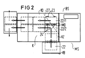
- FIG. 2 shows a schematic illustration of the paper flow of the device in single sheet operation,
- FIG. 3 shows a schematic sectional illustration of a heat-setting station with belt transport,
- Figure 4 is a schematic sectional view of a heat-setting station with belt transport and associated integrated stripping device for the single sheets and
- Figure 5 is a schematic sectional view of the structure of the fixing straps.
Ein in der Figur 1 schematisch dargestelltes elektrofotografisches Druckgerät enthält einen bandförmigen Zwischenträger 10 in Form eines Fotoleiters, der über Führungsrollen 11 elektromotorisch angetrieben geführt ist. Um den Zwischenträger 10 gruppiert sind die verschiedenen Aggregate für den elektrofotografischen Prozeß. Diese sind im wesentlichen: Eine Ladeeinrichtung LE in Form eines Ladekorotrons zum Aufladen des Zwischenträgers; ein Zeichengenerator ZG mit einem Leuchtdiodenkamm zum zeichenabhängigen Belichten des Zwischenträgers; Entwicklerstationen EY, EM, EC und EB zum Einfärben des zeichenabhängig entladenen Ladungsbildes auf dem Zwischenträger 10 mit Hilfe von farbigem Toner. Dabei enthält die Entwicklerstation EY gelben Toner, die Entwicklerstation EM Toner mit der Farbe Magenta, die Entwicklerstation EC Toner der Farbe Cyan und die Entwicklerstation EB schwarzen Toner. Zum Entfernen des Resttoners nach der Entwicklung und dem Umdruck ist eine Reinigungsstation RS vorgesehen mit darin integrierter Reinigungsbürste 13. Die Entwicklerstationen EY, EM, EC und EB sind auswechselbar ausgestaltet und können z. B. über Gleitführungen aus dem Gerät herausgezogen und in das Gerät hereingeführt werden. Sie sind in üblicher Weise aufgebaut und enthalten Entwicklerwalzen 14 zum Einfärben des Ladungsbildes sowie an-und abschwenkbare Führungsrollen 11/1 bis 11/4 zum An- und Abschwenken des Zwischenträgers 10 an die Entwicklerwalzen 14 über elektromagnetische Schwenkeinrichtungen 15. Die Schwenkeinrichtungen 15 können dabei z. B. als Tauchankermagnete oder z. B. als Schwenkmagnete ausgebildet sein. Sie dienen dazu, die Entwicklerstationen EY, EM, EC und EB gesteuert von einer Steuerung des Gerätes einzeln mit dem Zwischenträger 10 zu koppeln.An electrophotographic printing device shown schematically in FIG. 1 contains a band-shaped
Im Abstand entlang von dem Zwischenträger sind zwei Umdruckstationen U1 und U2 angeordnet, die dazu dienen, ein auf dem Zwischenträger 10 erzeugtes Tonerbild auf einen Aufzeichnungsträger zu übertragen. Die Umdruckstationen U1 und U2 enthalten jeweils ein bandförmiges Transferelement 16, das in dem dargestellten Ausführungsbeispiel als Fotoleiterband ausgebildet ist. Die Transferelemente 16 werden elektromotorisch angetrieben und sind auf Führungsrollen 11 gelagert. Die Umdruckstationen weisen einen Transferbereich T auf, der dazu dient, Tonerbilder auf dem Zwischenträger 10 auf die Transferelemente 16 zu übertragen. Zu diesem Zwecke sind verschwenkbare Führungsrollen 11/5 und 11/6 vorgesehen, über die der Zwischenträger 10 in den Transferbereichen T an die Transferelemente 16 an- und abgeschwenkt werden kann. Zur Übertragung eines Tonerbildes von dem Zwischenträger 10 auf die Transferelemente 16 befindet sich im Transferbereich T gegenüber den Führungsrollen 11/5 und 11/6 ein Umdruckkorotron 17. Zum An- und Abschwenken der Führungsrollen 11/5 und 11/6 sind wie bei den Entwicklerstationen elektromotorische Schwenkeinrichtungen 15 vorgesehen. Zum Übertragen des Tonerbildes vom Zwischenträger 10 auf das Transferelement 16 wird der Zwischenträger 10 in Kontakt mit dem Transferelement 16 gebracht und über das Umdruckkorotron 17 mit Hilfe von Ladungskräften auf das Transferelement 16 übertragen. Bei dieser Übertragung wird das Transferelement 16 im Bereich der Transferbereiche T in Gleichlauf mit dem Zwischenträger 10 mitbewegt.At a distance along the intermediate carrier, two transfer printing stations U1 and U2 are arranged, which serve to transfer a toner image generated on the
Es ist auch denkbar, anstelle der schwenkbaren Führungsrollen 11/5 und 11/6 ortsfeste Führungsrollen anzuordnen und dafür die Führungsrollen 11 des Transferbereiches T für die Transferelemente 16 an- und abschwenkbar auszugestalten.It is also conceivable to arrange stationary guide rollers instead of the
Dem Transferbereich T in Bewegungsrichtung bei der Übertragung des Transferelementes nachgeordnet ist ein Zusatzkorotron 19.An
Es dient zur Festigung des auf dem Transferelement 16 befindlichen Tonerbildes. Die Anordnung eines derartigen Zusatzkorotrons 19 kann günstig sein, wenn mit der Druckeinrichtung in Vierfarbendruck gedruckt wird, bei dem mehrere Einzelbilder verschiedener Farben übereinander gedruckt werden, folglich ein Tonerbild viermal den Transferbereich T durchläuft.It serves to strengthen the toner image on the
Zur Übertragung der auf den Transferelementen 16 befindlichen Tonerbilder auf einen Aufzeichnungsträger weisen die Umdruckstationen U1 und U2 Umdruckbereiche UB auf. Diese bestehen jeweils aus einer Führungsrolle mit einem gegenüber der Führungsrolle angeordneten Umdruckkorotron. Der Umdruckbereich UB1 der ersten Umdruckstation ist zum Bedrucken einer Frontseite des Aufzeichnungsträgers auf der einen Seite eines Transportkanales K angeordnet und der Umdruckbereich UB2 der zweiten Umdruckstation zum Bedrucken einer Rückseite eines Aufzeichnungsträgers auf der anderen Seite des Transportkanales K. Der Transportkanal K dient dabei zur Zuführung des Aufzeichnungsträgers zu den Umdruckbereichen UB1 und UB2.In order to transfer the toner images located on the
Zur Reinigung der Transferelemente 16 nach dem Umdruck sind Reinigungsstationen RS vorgesehen. Diese sind entsprechend der Reinigungsstation RS des Zwischenträgers 10 ausgebildet. Sie enthalten ebenfalls eine Reinigungsbürste 13 sowie Reinigungskorotrons 20 zum Lockern des Toners vor der Reinigung bzw. zum Entladen des Transferelementes 16 oder des Zwischenträgers 10 vor der Reinigung.Cleaning stations RS are provided for cleaning the
Angetrieben werden die Transferelemente 16 und der Zwischenträger 10 über am Boden des Gerätes angeordnete Elektromotoren M1 bis MN, die über Riemenantriebe 21 mit den Führungsrollen 11 gekoppelt sind. Das Transferelement 16 der unteren Umdruckstation U1 wird dabei nur in einer Richtung (Pfeilrichtung) bewegt. Die Bewegungsrichtung entspricht dabei der Bewegung des Transferelementes 16 bei der Übertragung eines Tonerbildes. Das Transferelement 16 der oberen Umdruckstation U2 ist jedoch in beiden Richtungen bewegbar. Bei dem Transfer eines Einzeltonerbildes von dem Zwischenträger 10 auf das Transferelement 16 wird das Transferelement 16 der oberen Umdruckstation U2 mit dem Zwischenträger 10 in Pfeilrichtung mitbewegt. Nach der Übertragung der Tonerbilder auf das Transferelement 16 der oberen Umdruckstation U2 wird der Kontakt des Transferelementes 16 mit dem Zwischenträger 10 gelöst und zum Umdruck des Tonerbildes auf den Aufzeichnungsträger die Bewegung des Transferelementes 16 der Umdruckstation U2 umgekehrt (Pfeilrichtung).The
Die schwenkbaren Führungsrollen 11/5 und 11/6 dienen deswegen zur alternativen Erzeugung einer Transferstellung, bei der Tonerbilder von dem Zwischenträger 10 auf das Transferelement 16 übertragen werden und einer Bereitschaftstellung, bei der Zwischenträger 10 und Transferelement 16 zueinander derart beabstandet sind, daß keine Übertragung von Tonerbildern erfolgt.The
Den Umdruckbereichen UB1 und UB2 zugeführt wird, entsprechend der Darstellung der Figur 2, ein blattförmiger Aufzeichnungsträger 22 über den Transportkanal K. Der Transportkanal K besteht dabei aus dem eigentlichen Druckkanal KD und einem Zuführkanal KZ. Ausgehend von einem seitlich am Druckgerät anordbaren Vorratsbereich VB werden die Einzelblätter 22 hintereinander über den Zuführkanal KZ dem Druckkanal KD zugeführt. Der Mündungsbereich ist dabei in einem durch Umdruckstationen U1 und U2 und dem Zwischenträger 10 begrenzten Gerätebereich angeordnet.According to the illustration in FIG. 2, the transfer printing areas UB1 and UB2 are supplied with a sheet-shaped
In diesem Mündungsbereich ist eine Richtungs-Umlenkeinrichtung für den Aufzeichnungsträger angeordnet. Diese besteht bei der Ausbildung des Druckgerätes als Einzelblattdrucker aus festen Anschlägen 23 und beweglichen Anschlägen 24 sowie einer Papiertransporteinrichtung PT. Die festen Anschläge 23 sind am hinteren Ende des Zuführkanals KZ im Mündungsbereich zwischen Zuführkanal und Druckkanal fest angeordnet. Sie begrenzen den hinteren Anschlag eines über den Zuführkanal KZ zugeführten Einzelblattes 22. Mittig zum Druckkanal KD im Mündungsbereich befinden sich die beweglich ein- und ausschwenkbaren Anschläge 24. Das Ein- und Ausschwenken erfolgt dabei über Elektromotoren oder Magnete MO.A direction deflection device for the recording medium is arranged in this mouth region. When the printing device is designed as a single-sheet printer, this consists of fixed stops 23 and
Der Druckkanal KD ist zum parallelen Transport von mindestens zwei nebeneinander angeordneten Einzelblättern 22/1 und 22/2 eines ersten Formates, in diesem Fall A4 ausgelegt und zum Transport von Einzelblättern eines zweiten Formates, in diesem Fall A3. Zum parallelen Transport von zwei Einzelblättern im A4 Format werden die Einzelblätter über den Vorratsbereich VB einzeln hintereinander zugeführt. Dabei stößt ein erstes zugeführtes Blatt 22/1 mit seinen seitlichen Rändern an den festen Anschlag 23. Danach werden die beweglichen Anschläge 24 mittig in den Mündungsbereich zwischen Druckkanal KD und Zuführkanal KZ eingefahren, so daß das zweite Einzelblatt 22/2 mit seinen seitlichen Rändern zur Anlage an die beweglichen Anschläge 24 kommt. Die beiden Einzelblätter 21/1 und 21/2 können nunmehr mit Hilfe der Papiertransporteinrichtung PT parallel den Umdruckbereichen UB1 und UB2 der Umdruckstationen U1 und U2 zugeführt werden. Wie in der Figur 1 und 2 dargestellt, besteht die Papiertransporteinrichtung aus motorisch angetriebenen Papiertransportrollen 26, die Einzelblätter im Druckkanal KD transportieren sowie aus Papiertransportbändern 25, die auf Rollen gelagert sind und die sich bis in den Zuführkanal KZ erstrekken. Papiertransportbänder 25 und Papiertransportrollen 26 sind senkrecht zueinander angeordnet. Die Papiertransportbänder 25 erfassen die Einzelblätter 22 im Zuführkanal KZ und legen sie an den Anschlägen 23 und 24 ab. Danach werden die parallel nebeneinander angeordneten Einzelblätter über die Papiertransportrollen 26 weitertransportiert.The pressure channel KD is designed for the parallel transport of at least two
Werden anstelle von zwei Einzelblättern im A4 Format Einzelblätter im A3 Format verwendet, so werden die beweglichen Anschläge 24 aus dem Transportbereich der Papiertransportkanäle herausgefahren. Damit kommt ein zugeführtes A3 Blatt mit seiner oberen Kante in Anschlag mit den festen Anschlägen 23. Danach wird es im Querformat weitertransportiert und im Querformat bedruckt. Die Orientierung des aufgebrachten Druckbildes auf den Einzelblättern kann mit Hilfe einer elektronischen Seitendreheinrichtung erfolgen, die in üblicher Weise ausgebildet ist. Damit ist es möglich quer im Querformat angegebene Blätter so zu beschreiben, daß ein hochformatig beschriebenes Einzelblatt entsteht. Derartige Seitendreheinrichtungen sind allgemein bekannt.If single sheets in A3 format are used instead of two single sheets in A4 format, the
Soll die Druckeinrichtung mit Endlospapier betrieben werden, so ist es notwendig, das über den Vorratsbereich VB zugeführte Endlospapier im Bereich der Richtungs-Umlenkeinrichtung umzulenken. In diesem Fall kann im Mündungsbereich von Zuführkanal KZ und Druckkanal KD z. B. ein Umlenkbalken 27 (Figur 2) angeordnet sein. Dieser Umlenkbalken 27 kann aus einer gegenüber der Papierzuführungsrichtung um 45° gedrehten Papierführungsrolle bestehen, die das Endlospapier um 90° umlenkt und den Umdruckbereichen zuführt. Zum Transport des Endlospapieres können in Bewegungsrichtung des Papieres vor und hinter dem Umlenkbalken 27 Papiertransportrollen angeordnet sein. Bei der Verwendung von Umdruckstation U1 und U2 mit einem in seiner Bewegungsrichtung umkehrbar antreibbaren Transferelement 16 ist es notwendig, den Endlos-Aufzeichnungsträger im Start-Stop-Betrieb zu betreiben. Dies kann durch entsprechenden Antrieb der den Papiertransport bewerkstelligenden Antriebsrollen geschehen.If the printing device is to be operated with continuous paper, it is necessary to deflect the continuous paper fed via the supply area VB in the area of the directional deflection device. In this case, in the mouth area of the feed channel KZ and pressure channel KD z. B. a deflecting beam 27 (Figure 2) may be arranged. This deflecting
Zum Fixieren der Tonerbilder auf dem Aufzeichnungsträger 22 ist eine Thermodruckfixierstation FX angeordnet. Diese kann z. B. entsprechend den Ausführungsformen der Figuren 3 oder 4 ausgebildet sein. Sie enthält ein Fixierwalzenpaar mit einer ortsfesten Fixierwalze 28 und einer z. B. unter der Kraft einer Feder 29 gegen die Fixierwalze 28 drückende Andruckwalze 30. Sowohl Andruckwalze 30 als auch Fixierwalze 28 bestehen aus einer Aluminiumhohlwalze mit darin angeordneter Strahlerheizung 31 in Form einer Halogenheizung. Die Fixierwalzen 28, 30 sind bezüglich ihrer linienförmigen Kontaktzone, dem eigentlichen Druckbereich der Fixierwalzen, am Ende eines Zuführungskanales 32 für den Aufzeichnungsträger angeordnet, sie haben beispielsweise einen Durchmesser von 60 mm oder bevorzugt 80 mm. Der Zuführungskanal 32 verläuft in gerader Verlängerung zu dem Transportkanal K. Gebildet wird der Zuführungskanal 32 durch wärmebeständige untere und obere Fixierbänder 33/1 und 33/2, die jeweils die Fixierwalze 28 bzw. die Andruckwalze 30 und eine eingangsseitige Umlenkstelle 34 umschlingen. Diese eingangsseitige Umlenkstelle 34 enthält Walzen, die z. B. in Form von Spannrollen ausgebildet sind mit einem Durchmesser von etwa 30 mm und die z. B. über Federn 39 die Fixierbänder 33 straffen. Die Umlenkstelle 34 führt in Verbindung mit den Fixierwalzen 28 bzw. den Andruckwalzen 30 die Fixierbänder 33 derart, daß sich ein konisch verlaufender Zuführkanal 32 ergibt, der ausgehend von einem Zuführbereich 35 bis zu der Kontaktzone zwischen den Walzen in einem vorgebbaren Zuführwinkel α abnimmt. Der Zuführbereich 35 hat dabei eine lichte Weite, die etwas stärker ist als die Stärke des Aufzeichnungsträgers (z. B. 1,5 mm).A thermal print fixing station FX is arranged to fix the toner images on the
In dem Zwischenraum zwischen den vor- und zurücklaufenden Fixierbändern 33 befinden sich Heizelemente 36, in Form von elektrisch beheizten Infrarotelementen. Um eine gleichmäßige Aufheizung des Fixierbandes 33 zu ermöglichen, können die Wendel der Heizelemente zueinander versetzt angeordnet sein. Die Heizelemente 36 dienen zur Erwärmung der Fixierbänder auf eine Fixiertemperatur von etwa 120 bis 200°. Bei dem in der Figur 3 dargestellten Ausführungsbeispiel bestehen sie entsprechend der Figur 5 aus einem mehrschichtig aufgebauten elastischem hitzebeständigen Band mit einer Metallschicht aus Gewebe oder Laminat aus Nickel 37 mit z. B. einer Stärke von etwa 0,1 - 0,5 mm und einer Beschichtung 38 aus tonerabweisendem Material, z. B. PTFE/Silikon mit z.B. einer Stärke von etwa 1,5 - 2 mm. Ein derartig elastisch ausgebildetes Fixierband ist zum Fixieren von Zweikomponententoner geeignet. Zum Fixieren von Einkomponententoner bedarf es der Erzeugung eines erhöhten Druckes zwischen Fixierwalze 28 und Andruckwalze 30 in der Kontaktzone. Deswegen ist es in diesem Falle günstig, anstelle der Stützschicht der Figur 5 (Gewebe) eine Stützschicht aus Stahl zu verwenden und diese zu beschichten. Das Fixierband selbst ist dabei als Endlosband ausgebildet. Dadurch verringert sich die Bruchgefahr, z.B. an der Schweißstelle und die Gefahr einer Wulstbildung wird vermindert. Ein derartiges Endlosband kann dabei in einfacher Weise dadurch erzeugt werden, daß man ein endloses Stahlband oder z. B. ein endloses Gewebeband walzenartig aufspannt und mit einer Schicht aus PTFE beschichtet. Es ist auch denkbar, auf einer Fertigungswalze selbst durch Auftragen, eine Stützschicht aus Gewebe oder Laminat zu erzeugen, zu beschichten und dann von der Fertigungswalze das fertige Endlosband abzuziehen.
Anstelle der Beheizung mit Infrarotelementen 36 ist es auch möglich auf diese Heizelemente zu verzichten und das Fixierband 33 selbst elektrisch zu beheizen. Das Fixierband kann dabei bezüglich seiner Stützschicht 37 als ein mit Widerstandselementen durchsetztes Laminat oder Gewebe sein, das z. B. entsprechend einer elastischen Heizdecke ausgebildet ist. Die Stromversorgung einer derartigen Stützschicht kann dann über Schleifkontakte 40 erfolgen, die die Fixierbänder 33 von innen kontaktieren. Es ist jedoch auch möglich das Metallgewebe mit Hilfe einer Induktionsheizung zu beheizen.Instead of heating with
Um ein Anhaften von Toner auf den Fixierwalzen 28 bzw. 30 zu verhindern, werden die Fixierwalzen in üblicherweise mit Trennöl eingeölt. Zu diesem Zwecke sind Beölungsstationen 41 vorgesehen. Diese können entsprechend der Ausführungsform der Figur 4 in der Umgebung der Fixierwalzen 28 angeordnet sein oder bei einer Ausführungsform entsprechend der Figur 3 im Bereich der Fixierbänder 33. In den Beölungsstationen 41 wird mit Hilfe eines Dochtes 42 oder eines Vlieses Trennöl auf die beschichtete Seite der Fixierbänder 33 aufgetragen.In order to prevent toner from adhering to the fixing
Zur Verminderung des Wärmeverlustes und zur Unterstützung der gleichmäßigen Erhitzung der Fixierbänder 33 auf die Fixiertemperatur ist die Fixierstation über ein isolierendes Gehäuse 43 abgedeckt. Es erstreckt sich beidseitig der Fixerstation über die gesamte Breite der Fixierbänder 33. Durch die Wärmeisolierung wird ein Aufheizen der Umgebung verhindert und kurze Aufheizzeiten beim Einschalten der Fixierstation ermöglicht. Weiterhin verringert ein derartiges Gehäuse den Wärmeverlust während des Standby-Betriebes.To reduce the heat loss and to support the uniform heating of the fixing straps 33 to the fixing temperature, the fixing station is covered by an insulating
Ein Problem bei Thermodruckfixierstationen ist das sogenannte "Stripping" der Einzelblätter beim Fixieren. Darunter versteht man das Auslenken des Einzelblattes aus der Kanalrichtung durch Adhäsionskräfte der Walze. Ein derartiges Auslenken kann auch auftreten, wenn wie bei der vorliegenden Fixierstation im Duplexbetrieb auf beiden Seiten ein Tonerbild angeordnet ist. Das Tonerbild hat abhängig vom erzeugten Druckbild unterschiedliche Größe und damit kann das Einzelblatt stärker an der einen oder anderen Fixierwalze anhaften und dadurch ausgelenkt werden. Die Verwendung von mechanischen Abstreifelementen im Ausgangsbereich der Kontaktzone ist nicht zu empfehlen, weil nach Verlassen der Kontaktzone der Toner auf dem Einzelblatt noch weich ist. Die Abstreifelemente können dann das noch weiche Tonerbild verwischen.A problem with thermal printing fusing stations is the so-called "stripping" of the single sheets when fusing. This means the deflection of the single sheet from the direction of the channel by adhesive forces of the roller. Such a deflection can also occur if a toner image is arranged on both sides in duplex mode, as in the present fixing station. The The toner image has a different size depending on the print image generated and the single sheet can thus adhere more strongly to one or the other of the fixing rollers and thus be deflected. The use of mechanical scraper elements in the exit area of the contact zone is not recommended because the toner on the single sheet is still soft after leaving the contact zone. The stripping elements can then blur the still soft toner image.
Zur Vermeidung eines derartigen Strippingfehlers sind bei einer bevorzugten Ausführungsform in Verlängerung des Zuführkanales 32 in einem Ausgabekanal 44 ausgangsseitige Umlenkstellen 45 in der Bandkonstruktion integriert. Um diese Umlenkstellen 45 sind die Fixierbänder 33 zusätzlich geführt. Sie weisen einen Durchmesser auf, der geringer ist als der Durchmesser der Fixierwalzen 28, z. B. 30 mm bei einem Durchmesser der Fixierwalzen von 60 mm oder bevorzugt 80 mm, der Durchmesser der Umlenkstellen 45 ist dabei so bemessen, daß die Einzelblätter sich unmittelbar von der Umlenkstelle bei der Durchführung ablösen. Durch die gleichzeitige geradlinige Führung in dem Ausgabekanal 44 über die beiden Fixierbänder 33 können sich die Einzelblätter nicht verformen und auch nicht einseitig abgelenkt weroen.To avoid such a stripping error, in a preferred embodiment, in the extension of the
Werden als Fixierbänder 33 elastische Bänder verwendet, so ist, wie bereits beschrieben, die Verwendung von Straffungsmittel in Form von Spannrollen anzuraten. In diesem Falle ist es günstig, die Umlenkstellen 45 der sogenannten "Anti-Stripping-Einrichtung" als Spannrollen auszubilden. Jede Verschiebung der eingangsseitigen Walzen 34 verändert evtl. die Länge der Fixierbänder, was zu unterschiedlich langen Fixierbändern in der oberen und unteren Fixierstation führt. Das Resultat wären unterschiedliche Bandgeschwindigkeiten mit ungenügendem Transport der Einzelblätter 22 zwischen den Fixierbändern. Eine derartige Längung der Fixierbänder wird vermieden, wenn die Umlenkstellen 45 des Ausgabekanales 44 als Spannrollen ausgebildet sind, weil sich eine derartige Längung auf den Transport der Einzelblätter im eigentlichen Fixierbereich 32 nicht mehr auswirkt.If 33 elastic bands are used as the fixing bands, it is advisable, as already described, to use tensioning agents in the form of tensioning rollers. In this case, it is favorable to design the deflection points 45 of the so-called "anti-stripping device" as tension rollers. Each shift of the
Um die lichte Weite des Zuführbereiches 35 in Abhängigkeit von der Stärke des verwendeten Aufzeichnungsträgers verändern zu können und damit eine Einstellung der Zuführwinkels α zu ermöglichen, können die Umlenkstellen 34 in einstellbaren Lagerelementen 46 befestigt sein. Diese einstellbaren Lagerelemente 46 können dabei mit Stellmotoren ausgerüstet sein. Durch Betätigung der Stellmotore können die Umlenkstellen mit den darin angeordneten Walzen senkrecht zur Transportrichtung des Aufzeichnungsträgers verschoben werden. Dabei ist es denkbar, diese Einstellung z. B. mit Hilfe der Steuereinrichtung des Druckgerätes vorzunehmen, wobei die Eingabe des Kanalwinkels α über ein Bedienteil D mit Display auf dem Gerät erfolgen kann.In order to be able to change the clear width of the
Die Thermo-Fixierstation funktioniert dabei wie folgt: Ein in der Umdruckstation UB mit einem Tonerbild versehenes Einzelblatt wird über den Zuführbereich 35 dem Fixierbereich der Thermo-Fixierstation zugeführt (Position 1, Figur 3). Die beiden Fixierbänder 33/1 und 33/2 erfassen weich die Vorderkante des Einzelblattes 22 und zwar unabhängig von der Stärke des Einzelblattes (Position 2). Dies ist insbesondere dann der Fall, wenn als Fixierbänder 33 elastische Bänder verwendet werden. Es ist also möglich, prinzipiell auf die Lagerelemente 46 zu verzichten. Sie sind jedoch günstig zur Einstellung der Position, bei der das Einzelblatt erstmalig in Berührung mit den Fixierbändern 33 kommt und damit günstig zur Justierung und Abstimmung der Fixierstation mit den Transportelementen des eigentlichen Transportkanales der Druckeinrichtung.The thermal fixing station functions as follows: A single sheet provided with a toner image in the transfer printing station UB is fed via the
Der konisch zulaufende Fixierkanal 32 ermöglicht also ein weiches Einphasen der Einzelblätter in den eigentlichen Fixierbereich. Danach wird der Aufzeichnungsträger mit gleicher Prozeßgeschwindigkeit VP wie in den Umdruckbereichen UB weitergeführt. Durch das weiche Einphasen erleidet der Aufzeichnungsträger an seiner Vorderkante keinen Rückstoß beim Einlaufen in die Fixierstation. Damit kann sich das Papier nicht aufwölben. Das gleiche gilt für die Zuführung des Einzelblattes zur Kontaktzone zwischen den Fixierwalzen. Auch hier erfolgt eine rückstoßfreie Zuführung mit Prozeßgeschwindigkeit VP. Dies verringert die Stoßbelastung an der Aufzeichnungsträgerkante und die Stoßbelastung der Fixierwalzen, weil der Aufzeichnungsträger keilförmig zugeführt wird. Als Ergebnis verlängert sich die Lebensdauer der Walzen und der Mechanik.The tapered fixing
Durch die Zwangsführung in der gesamten Fixierstation und insbesondere im Zuführkanal 32 des Aufzeichnungsträgers kann auf die Verwendung von Saugtischen oder ähnlichen Steuerelementen für den Aufzeichnungsträger verzichtet werden. Die Fixierstation kann unmittelbar angrenzend an den Umdruckbereich bzw. die Umdruckstation UB angeordnet sein.Due to the forced guidance in the entire fixing station and in particular in the
Nach Einphasung des Einzelblattes 22 in den Fixierbereich der Fixierstation legen sich die Fixierbänder 33 gleichmäßig über die Vorder- und Rückseite des Einzelblattes. Damit kommt es zu einer langsamen konstanten Aufheizung von Toner und Papier im Fixierbereich während des Transportes des Einzelblattes durch den Fixierbereich 32. Der Toner wird auf Fixiertemperatur gebracht. Beim Einlaufen in den eigentlichen Kontaktbereich zwischen den Fixierwalzen 28, 30 ist der Toner bereits teigig. Damit ist es möglich, den Fixierdruck, d. h. den Druck der Andruckwalze gegen die Fixierwalze, gering zu halten. Im Ergebnis ergibt sich eine schonendere Papierbehandlung und die Gefahr von Papierwelligkeit wird minimiert.After the
Die beschriebene Thermo-Fixierstation läßt sich bevorzugt in Druck- oder Kopiergeräten mit einem Umdruckprinzip verwenden, wie es in Zusammenhang mit der Figur 1 beschrieben wurde. Es ist jedoch auch möglich eine derartige Fixierstation bei üblichen Druck- oder Kopiergeräten zu verwenden, bei denen im Duplexbetrieb ein zweimaliger Durchlauf durch die Fixierstation erfolgt und bei dem die Fixierstation mit einer Wendeeinrichtung gekoppelt ist. In diesem Fall müssen die Fixierbänder 33 nur auf der Fixierseite mit Heizelementen 36 ausgerüstet sein. Die Heizelemente, z. B. der oberen Fixierbänder 33/2 können damit entfallen.The described thermal fusing station can preferably be used in printing or copying machines with a transfer printing principle, as was described in connection with FIG. 1. However, it is also possible to use a fixing station of this type in conventional printing or copying devices in which a duplex operation involves two passes through the fixing station and in which the fixing station is coupled to a turning device. In this case, the fixing straps 33 only have to be equipped with
Es ist auch denkbar die Heizelemente 36 der Fixierbänder mit der Steuerung zu koppeln und in Abhängigkeit von der Betriebsart zu steuern. Beim Beschreiben eines Einzelblattes im Duplexbetrieb ist es dann notwendig, beide Fixierbänder zu beheizen. Wird im Simplexbetrieb nur eine Seite des Einzelblattes beschrieben, ist die Aktivierung der Heizelemente von nur einem Fixierband notwendig. Die Heizelemente können also bedarfsweise zuschaltbar ausgebildet sein.It is also conceivable to couple the
- 1010th
- ZwischenträgerIntermediate beam
- 1111
- FührungsrollenLeadership roles
- 11/1, 11/2,11/1, 11/2,
- an- und abschwenkbare Führungsrollenguide rollers that can be swiveled in and out
- 11/3, 11/4 11/5, 11/611/3, 11/4 11/5, 11/6
- Führungsrollen an- und abschwenkbar im TransferbereichGuide rollers can be swiveled in and out in the transfer area
- LELE
- LadeeinrichtungLoading device
- ZGZG
- ZeichengeneratorCharacter generator
- EYEY
- Entwicklerstation Farbe Yellow (Gelb)Developer station color yellow
- EMEM
- Entwicklerstation Farbe Magenta (Blau)Developer station color magenta (blue)
- ECEC
- Entwicklerstation Farbe Cyan (Rot)Developer station color cyan (red)
- EBEB
- Entwicklerstation Farbe Black (Schwarz)Developer station color black
- RSRS
- ReinigungsstationCleaning station
- 1313
- ReinigungsbürsteCleaning brush
- 1414
- EntwicklerwalzeDeveloper roller
- 1515
- elektromotorische Schwenkeinrichtungelectromotive swivel device
- U1U1
- Umdruckstation untenTransfer station below
- U2U2
- Umdruckstation obenTransfer station above
- UB1UB1
- Umdruckbereich untenTransfer area below
- UB2UB2
- Umdruckbereich obenTransfer area above
- 1616
- TransferelementTransfer element
- TT
- TransferbereichTransfer area
- 1717th
- UmdruckkorotronTransfer corotron
- 1919th
- ZusatzkorotronAdditional corotron
- KK
- TransportkanalTransport channel
- 2020th
- ReinigungskorotronCleaning corotron
- M1...M4M1 ... M4
- ElektromotorElectric motor
- 2121
- RiemenantriebBelt drive
- 2222
- AufzeichnungsträgerRecord carrier
- 22/1, 22/222/1, 22/2
- EinzelblätterSingle sheets
- KDKD
- DruckkanalPressure channel
- KZconcentration camp
- ZuführkanalFeed channel
- VBVB
- VorratsbereichStorage area
- 2323
- fester Anschlagfirm stop
- 2424th
- beweglicher Anschlagmovable stop
- PTPT
- PapiertransporteinrichtungPaper transport device
- 2525th
- PapiertransportbänderPaper conveyor belts
- 2626
- PapiertransportrollenPaper transport rollers
- 2727
- UmlenkbalkenDeflection beam
- 2828
- FixierwalzeFuser roller
- 2929
- Federfeather
- 3030th
- AndruckwalzePressure roller
- 3131
- StrahlerheizungHeater
- 3232
- Zuführkanal (Fixierbereich)Feed channel (fixing area)
- 33/1, 33/233/1, 33/2
- untere und obere Fixierbänderlower and upper fixing straps
- 3434
- UmlenkstellenDeflection points
- 3535
- ZuführbereichFeed area
- αα
- ZuführwinkelFeed angle
- 3636
- HeizelementeHeating elements
- 3737
- Gewebe, LaminatFabric, laminate
- 3838
- BeschichtungCoating
- 3939
- FedernspannrollenSpring tensioners
- 4040
- SchleifkontaktSliding contact
- 4141
- BeölungsstationOiling station
- 4242
- Docht, VliesWick, fleece
- 4343
- isolierendes Gehäuseinsulating housing
- 4444
- AusgabekanalOutput channel
- 4545
- ausgangsseitige Umlenkstellenoutput deflection points
- 4646
- einstellbare Lagerelementeadjustable bearing elements
- VPVP
- ProzeßgeschwindigkeitProcess speed
Claims (11)
- Thermofixing station for a printer or copier for fixing toner images on sheet-like recording carriers (22), with- a pair of fixing rollers having a lower (28) and an upper (30) fixing roller, of which at least one roller (28, 30) can be driven electromotively in order to generate a fixing pressure on a recording carrier in a linear contact zone between the fixing rollers (28, 30),- a feed channel (32) for feeding the recording carrier (22) to the pair of fixing rollers, and- a lower and an upper fixing belt (33/1, 33/2), each with an associated heating device (31, 36) for the simultaneous heating of the fixing belts (33/1, 33/2), each fixing belt (33/1, 33/2) being guided around a fixing roller (28) and at least one further deflection point (34) located on the entry side, in such a way that the fixing belts (33/1, 33/2) extend on both sides along the feed channel (32) and, at the same time, form a fixing region of wedge-shaped cross-section which, starting from a feed region (35), located on the entry side, to the contact zone between the fixing rollers (28, 30) narrows at a predetermined feed angle (α) in the conveying direction of the recording carrier, so that the recording carrier (22) provided with toner images can be phased smoothly into the fixing region and heated slowly and constantly to the fixing temperature.
- Thermofixing station according to Claim 1, characterized by
- a delivery channel (44) downstream of the pair of fixing rollers in the extension of the feed channel (32) and having deflection points (45) which are arranged on both sides of the delivery channel (44) and are located on the exit side and around which the fixing belts (33/1, 33/2) are additionally guided, in such a way that the recording carrier (22) peels off from the fixing belts (33) in the region of the deflection points (45). - Thermofixing station according to one of Claims 1 or 2, characterized in that the heating device (36) assigned to a fixing belt (33) is arranged on the side of the fixing belts (33) which faces away from the feed channel (32).
- Thermofixing station according to Claim 1, characterized in that the fixing belts (33) themselves are designed to be electrically heatable.
- Thermofixing station according to one of Claims 1 to 4, characterized in that a heating device assigned to a fixing roller (28) is designed as a radiant heater (31) and the heating device (36) assigned to the fixing belts (33) is designed as an infrared heater.
- Thermofixing station according to one of Claims 1 to 6, characterized by a thermally insulating housing (43) extending over the fixing station.
- Thermofixing station according to one of Claims 2 or 5, characterized by elastically designed fixing belts (33) having a clamping device arranged in the region of the deflection points (35) located on the exit side.
- Thermofixing station according to one of Claims 1 to 7, characterized by a fixing belt (33) of multi-layer construction, with a carrier layer (37) and with a layer (38) arranged on the latter and consisting of toner-repellent material.
- Thermofixing station according to one of Claims 1 to 8, characterized in that the fixing belts (33) are designed as endless belts.
- Thermofixing station according to Claim 1, characterized by
- means for setting the feed angle (α). - Printer or copier, with- an intermediate carrier (10) with an associated recording and developing station (ZG, EY, EM, EC, EB) for generating toner images on the intermediate carrier (10),- a first and a second transfer-printing station (U1, U2), each with a transfer element (16) for receiving a toner image from the intermediate carrier (10) in a transfer region (T) and for transmitting the toner image from the transfer element (16) onto a recording carrier (22) in a transfer-printing region (UB), the transfer regions (T) of the transfer-printing stations (U1, U2) being arranged at a distance from one another along the intermediate carrier (10),- a conveying channel (K) for conveying the recording carrier (22) out of a stock region (VB) to the transfer-printing region (UB) of the transfer-printing stations (U1, U2), the transfer-printing region (UB1) of the first transfer-printing station (U1) being arranged on one side of the conveying channel (K) for the printing of a front side of the recording carrier (22), and the transfer-printing region (UB2) of the second transfer-printing station (U2) being arranged on the other side of the conveying channel (K) for the printing of a rear side of the recording carrier (22), and- a thermofixing station (FX) according to Claim 1.
Applications Claiming Priority (3)
| Application Number | Priority Date | Filing Date | Title |
|---|---|---|---|
| DE4031140 | 1990-10-02 | ||
| DE4031140 | 1990-10-02 | ||
| PCT/DE1991/000724 WO1992006417A1 (en) | 1990-10-02 | 1991-09-11 | Thermo-fixing station with belt conveyor |
Publications (2)
| Publication Number | Publication Date |
|---|---|
| EP0551288A1 EP0551288A1 (en) | 1993-07-21 |
| EP0551288B1 true EP0551288B1 (en) | 1994-07-20 |
Family
ID=6415421
Family Applications (1)
| Application Number | Title | Priority Date | Filing Date |
|---|---|---|---|
| EP91915451A Expired - Lifetime EP0551288B1 (en) | 1990-10-02 | 1991-09-11 | Thermo-fixing station with belt conveyor |
Country Status (3)
| Country | Link |
|---|---|
| EP (1) | EP0551288B1 (en) |
| DE (1) | DE59102290D1 (en) |
| WO (1) | WO1992006417A1 (en) |
Families Citing this family (8)
| Publication number | Priority date | Publication date | Assignee | Title |
|---|---|---|---|---|
| EP0486723B1 (en) * | 1990-11-22 | 1994-06-08 | Siemens Nixdorf Informationssysteme Aktiengesellschaft | Heating unit for heating an image carrier in a printing or copying machine |
| DE69122592T2 (en) * | 1990-11-30 | 1997-02-27 | Canon Kk | Fixing device and associated ink jet recording device |
| JP2500414B2 (en) * | 1992-12-11 | 1996-05-29 | 日本電気株式会社 | Paper feeding mechanism of electrophotographic device |
| US5873020A (en) * | 1995-11-13 | 1999-02-16 | Minolta Co., Ltd. | Fixing device with endless belt |
| JP3482611B2 (en) * | 1997-02-14 | 2003-12-22 | 株式会社日立製作所 | Heating equipment |
| DE10064560A1 (en) * | 2000-12-22 | 2002-06-27 | Nexpress Solutions Llc | Process for double-sided printing and / or coating of a substrate |
| DE10064582B4 (en) | 2000-12-22 | 2004-03-04 | Nexpress Solutions Llc | Digital printing or copying machine |
| DE10301587A1 (en) * | 2003-01-17 | 2004-08-05 | Nexpress Solutions Llc | Procedure to transport media printed on face side for reverse side printing, with preheating of face side toner to above glass transition temperature |
Family Cites Families (4)
| Publication number | Priority date | Publication date | Assignee | Title |
|---|---|---|---|---|
| US3666247A (en) * | 1969-12-29 | 1972-05-30 | Ibm | Fusing device and method |
| US3810735A (en) * | 1972-12-26 | 1974-05-14 | Xerox Corp | Heat fixing apparatus for fusible material |
| US4242566A (en) * | 1980-03-21 | 1980-12-30 | Pitney Bowes Inc. | Heat-pressure fusing device |
| US4954845A (en) * | 1988-08-02 | 1990-09-04 | Canon Kabushiki Kaisha | Image fixing device and image forming apparatus with same |
-
1991
- 1991-09-11 EP EP91915451A patent/EP0551288B1/en not_active Expired - Lifetime
- 1991-09-11 WO PCT/DE1991/000724 patent/WO1992006417A1/en active IP Right Grant
- 1991-09-11 DE DE59102290T patent/DE59102290D1/en not_active Expired - Fee Related
Also Published As
| Publication number | Publication date |
|---|---|
| WO1992006417A1 (en) | 1992-04-16 |
| EP0551288A1 (en) | 1993-07-21 |
| DE59102290D1 (en) | 1994-08-25 |
Similar Documents
| Publication | Publication Date | Title |
|---|---|---|
| EP0570419B1 (en) | Copying machine with a belt-type image-carrier transfer element | |
| EP0699315B1 (en) | Electrographic printing device for printing recording media shaped as tapes of various widths | |
| DE3838021C2 (en) | ||
| EP1110125B1 (en) | Printer or copier for simultaneously printing a supporting material on both sides | |
| DE3341631A1 (en) | RECORDING DEVICE | |
| DE3811414A1 (en) | FIXING DEVICE FOR TONER IMAGES | |
| DE3833302A1 (en) | PAPER TRANSPORT FOR ELECTROPHOTOGRAPHIC IMAGE GENERATION | |
| EP0551288B1 (en) | Thermo-fixing station with belt conveyor | |
| DE102007003843B4 (en) | Imaging device | |
| EP0946902B1 (en) | Electrographic printing device with opposite-lying printing units | |
| DE3808477A1 (en) | DEVICE FOR SMOOTHING SINGLE SHEETS IN NON-MECHANICAL PRINTING AND COPYING DEVICES | |
| EP0608264B1 (en) | Printer or copier with an arrangement for printing both sides of a recording medium | |
| EP0772529B1 (en) | Transfer printing station for treating in parallel two recording medium webs | |
| DE19511529C2 (en) | Sheet transport device | |
| EP0478820B1 (en) | Printer or copier for printing simplex and duplex copies in one or more colours | |
| EP0771436B1 (en) | Multi-functional printing device for printing strip substrates | |
| DE19827254B4 (en) | Electrographic printing device with two printing units that print on a deflected material web | |
| EP0486723B1 (en) | Heating unit for heating an image carrier in a printing or copying machine | |
| DE4203265C2 (en) | Printing or copying machine with intermediate carriers arranged on both sides of a recording medium transport channel for single or multi-color simplex or duplex printing | |
| EP0946901B1 (en) | Electrographic printing device with two transfer printing areas | |
| WO2007082755A1 (en) | Printer or copier for printing carrier materials having various mechanical properties | |
| DE102005058953A1 (en) | Method and device for detecting the differential speed between an image carrier and a carrier material | |
| EP0711428B1 (en) | Device for transporting print media in printing or copying apparatus | |
| EP0855051A1 (en) | Electrographic printer with adjustable corona device | |
| WO2005040937A1 (en) | Method and device for correction for paper shrinkage |
Legal Events
| Date | Code | Title | Description |
|---|---|---|---|
| PUAI | Public reference made under article 153(3) epc to a published international application that has entered the european phase |
Free format text: ORIGINAL CODE: 0009012 |
|
| 17P | Request for examination filed |
Effective date: 19930218 |
|
| AK | Designated contracting states |
Kind code of ref document: A1 Designated state(s): DE FR GB NL |
|
| 17Q | First examination report despatched |
Effective date: 19931215 |
|
| GRAA | (expected) grant |
Free format text: ORIGINAL CODE: 0009210 |
|
| AK | Designated contracting states |
Kind code of ref document: B1 Designated state(s): DE FR GB NL |
|
| REF | Corresponds to: |
Ref document number: 59102290 Country of ref document: DE Date of ref document: 19940825 |
|
| GBT | Gb: translation of ep patent filed (gb section 77(6)(a)/1977) |
Effective date: 19940926 |
|
| ET | Fr: translation filed | ||
| PLBE | No opposition filed within time limit |
Free format text: ORIGINAL CODE: 0009261 |
|
| STAA | Information on the status of an ep patent application or granted ep patent |
Free format text: STATUS: NO OPPOSITION FILED WITHIN TIME LIMIT |
|
| 26N | No opposition filed | ||
| REG | Reference to a national code |
Ref country code: GB Ref legal event code: 732E |
|
| REG | Reference to a national code |
Ref country code: FR Ref legal event code: TP |
|
| NLS | Nl: assignments of ep-patents |
Owner name: OCE PRINTING SYSTEMS GMBH |
|
| PGFP | Annual fee paid to national office [announced via postgrant information from national office to epo] |
Ref country code: NL Payment date: 19970722 Year of fee payment: 7 |
|
| PG25 | Lapsed in a contracting state [announced via postgrant information from national office to epo] |
Ref country code: NL Free format text: LAPSE BECAUSE OF NON-PAYMENT OF DUE FEES Effective date: 19990401 |
|
| NLV4 | Nl: lapsed or anulled due to non-payment of the annual fee |
Effective date: 19990401 |
|
| REG | Reference to a national code |
Ref country code: GB Ref legal event code: IF02 |
|
| PGFP | Annual fee paid to national office [announced via postgrant information from national office to epo] |
Ref country code: GB Payment date: 20060823 Year of fee payment: 16 |
|
| PGFP | Annual fee paid to national office [announced via postgrant information from national office to epo] |
Ref country code: FR Payment date: 20060922 Year of fee payment: 16 |
|
| PGFP | Annual fee paid to national office [announced via postgrant information from national office to epo] |
Ref country code: DE Payment date: 20070928 Year of fee payment: 17 |
|
| GBPC | Gb: european patent ceased through non-payment of renewal fee |
Effective date: 20070911 |
|
| REG | Reference to a national code |
Ref country code: FR Ref legal event code: ST Effective date: 20080531 |
|
| PG25 | Lapsed in a contracting state [announced via postgrant information from national office to epo] |
Ref country code: FR Free format text: LAPSE BECAUSE OF NON-PAYMENT OF DUE FEES Effective date: 20071001 |
|
| PG25 | Lapsed in a contracting state [announced via postgrant information from national office to epo] |
Ref country code: GB Free format text: LAPSE BECAUSE OF NON-PAYMENT OF DUE FEES Effective date: 20070911 |
|
| PG25 | Lapsed in a contracting state [announced via postgrant information from national office to epo] |
Ref country code: DE Free format text: LAPSE BECAUSE OF NON-PAYMENT OF DUE FEES Effective date: 20090401 |