EP0946409B1 - Process for the manufacture of hydrogen peroxide - Google Patents
Process for the manufacture of hydrogen peroxide Download PDFInfo
- Publication number
- EP0946409B1 EP0946409B1 EP97945830A EP97945830A EP0946409B1 EP 0946409 B1 EP0946409 B1 EP 0946409B1 EP 97945830 A EP97945830 A EP 97945830A EP 97945830 A EP97945830 A EP 97945830A EP 0946409 B1 EP0946409 B1 EP 0946409B1
- Authority
- EP
- European Patent Office
- Prior art keywords
- reaction
- hydrogen
- catalyst
- reactor
- hydrogen peroxide
- Prior art date
- Legal status (The legal status is an assumption and is not a legal conclusion. Google has not performed a legal analysis and makes no representation as to the accuracy of the status listed.)
- Expired - Lifetime
Links
- MHAJPDPJQMAIIY-UHFFFAOYSA-N Hydrogen peroxide Chemical compound OO MHAJPDPJQMAIIY-UHFFFAOYSA-N 0.000 title claims abstract description 70
- 238000004519 manufacturing process Methods 0.000 title claims abstract description 15
- 238000000034 method Methods 0.000 title claims description 38
- 230000008569 process Effects 0.000 title claims description 29
- 239000003054 catalyst Substances 0.000 claims abstract description 69
- 229910052739 hydrogen Inorganic materials 0.000 claims abstract description 39
- 239000001257 hydrogen Substances 0.000 claims abstract description 39
- KDLHZDBZIXYQEI-UHFFFAOYSA-N Palladium Chemical compound [Pd] KDLHZDBZIXYQEI-UHFFFAOYSA-N 0.000 claims abstract description 38
- UFHFLCQGNIYNRP-UHFFFAOYSA-N Hydrogen Chemical compound [H][H] UFHFLCQGNIYNRP-UHFFFAOYSA-N 0.000 claims abstract description 35
- 239000012429 reaction media Substances 0.000 claims abstract description 29
- QVGXLLKOCUKJST-UHFFFAOYSA-N atomic oxygen Chemical compound [O] QVGXLLKOCUKJST-UHFFFAOYSA-N 0.000 claims abstract description 27
- 229910052760 oxygen Inorganic materials 0.000 claims abstract description 27
- 239000001301 oxygen Substances 0.000 claims abstract description 27
- 229910052763 palladium Inorganic materials 0.000 claims abstract description 18
- 238000006243 chemical reaction Methods 0.000 claims description 38
- 239000007789 gas Substances 0.000 claims description 20
- 239000012495 reaction gas Substances 0.000 claims description 19
- XLYOFNOQVPJJNP-UHFFFAOYSA-N water Substances O XLYOFNOQVPJJNP-UHFFFAOYSA-N 0.000 claims description 18
- 229910052751 metal Inorganic materials 0.000 claims description 16
- 239000002184 metal Substances 0.000 claims description 16
- OKKJLVBELUTLKV-UHFFFAOYSA-N Methanol Chemical compound OC OKKJLVBELUTLKV-UHFFFAOYSA-N 0.000 claims description 15
- 239000000203 mixture Substances 0.000 claims description 14
- 239000007788 liquid Substances 0.000 claims description 9
- 239000002253 acid Substances 0.000 claims description 7
- QTBSBXVTEAMEQO-UHFFFAOYSA-N Acetic acid Chemical compound CC(O)=O QTBSBXVTEAMEQO-UHFFFAOYSA-N 0.000 claims description 6
- 229910000510 noble metal Inorganic materials 0.000 claims description 5
- BASFCYQUMIYNBI-UHFFFAOYSA-N platinum Chemical compound [Pt] BASFCYQUMIYNBI-UHFFFAOYSA-N 0.000 claims description 4
- 230000003197 catalytic effect Effects 0.000 claims description 3
- 229910052709 silver Inorganic materials 0.000 claims description 3
- 239000004332 silver Substances 0.000 claims description 3
- RYGMFSIKBFXOCR-UHFFFAOYSA-N Copper Chemical compound [Cu] RYGMFSIKBFXOCR-UHFFFAOYSA-N 0.000 claims description 2
- BQCADISMDOOEFD-UHFFFAOYSA-N Silver Chemical compound [Ag] BQCADISMDOOEFD-UHFFFAOYSA-N 0.000 claims description 2
- 229910052802 copper Inorganic materials 0.000 claims description 2
- 239000010949 copper Substances 0.000 claims description 2
- PCHJSUWPFVWCPO-UHFFFAOYSA-N gold Chemical compound [Au] PCHJSUWPFVWCPO-UHFFFAOYSA-N 0.000 claims description 2
- 229910052737 gold Inorganic materials 0.000 claims description 2
- 239000010931 gold Substances 0.000 claims description 2
- 229910052741 iridium Inorganic materials 0.000 claims description 2
- GKOZUEZYRPOHIO-UHFFFAOYSA-N iridium atom Chemical compound [Ir] GKOZUEZYRPOHIO-UHFFFAOYSA-N 0.000 claims description 2
- 229910052697 platinum Inorganic materials 0.000 claims description 2
- 229910052703 rhodium Inorganic materials 0.000 claims description 2
- 239000010948 rhodium Substances 0.000 claims description 2
- MHOVAHRLVXNVSD-UHFFFAOYSA-N rhodium atom Chemical compound [Rh] MHOVAHRLVXNVSD-UHFFFAOYSA-N 0.000 claims description 2
- GBMDVOWEEQVZKZ-UHFFFAOYSA-N methanol;hydrate Chemical compound O.OC GBMDVOWEEQVZKZ-UHFFFAOYSA-N 0.000 claims 1
- 230000001476 alcoholic effect Effects 0.000 abstract description 3
- 239000004744 fabric Substances 0.000 description 21
- 239000000243 solution Substances 0.000 description 14
- 238000000576 coating method Methods 0.000 description 10
- QAOWNCQODCNURD-UHFFFAOYSA-N Sulfuric acid Chemical compound OS(O)(=O)=O QAOWNCQODCNURD-UHFFFAOYSA-N 0.000 description 8
- 150000002739 metals Chemical class 0.000 description 8
- 229910000831 Steel Inorganic materials 0.000 description 7
- 230000015572 biosynthetic process Effects 0.000 description 7
- 239000011248 coating agent Substances 0.000 description 7
- 238000005755 formation reaction Methods 0.000 description 7
- 239000012071 phase Substances 0.000 description 7
- 239000010959 steel Substances 0.000 description 7
- CSCPPACGZOOCGX-UHFFFAOYSA-N Acetone Chemical compound CC(C)=O CSCPPACGZOOCGX-UHFFFAOYSA-N 0.000 description 6
- IJGRMHOSHXDMSA-UHFFFAOYSA-N Atomic nitrogen Chemical compound N#N IJGRMHOSHXDMSA-UHFFFAOYSA-N 0.000 description 6
- VEXZGXHMUGYJMC-UHFFFAOYSA-N Hydrochloric acid Chemical compound Cl VEXZGXHMUGYJMC-UHFFFAOYSA-N 0.000 description 6
- NBIIXXVUZAFLBC-UHFFFAOYSA-N Phosphoric acid Chemical compound OP(O)(O)=O NBIIXXVUZAFLBC-UHFFFAOYSA-N 0.000 description 6
- RTZKZFJDLAIYFH-UHFFFAOYSA-N Diethyl ether Chemical compound CCOCC RTZKZFJDLAIYFH-UHFFFAOYSA-N 0.000 description 5
- 239000012153 distilled water Substances 0.000 description 5
- 239000002360 explosive Substances 0.000 description 5
- 239000000835 fiber Substances 0.000 description 5
- 238000000465 moulding Methods 0.000 description 5
- LFQSCWFLJHTTHZ-UHFFFAOYSA-N Ethanol Chemical compound CCO LFQSCWFLJHTTHZ-UHFFFAOYSA-N 0.000 description 4
- UORVGPXVDQYIDP-UHFFFAOYSA-N borane Chemical compound B UORVGPXVDQYIDP-UHFFFAOYSA-N 0.000 description 4
- 238000010924 continuous production Methods 0.000 description 4
- 238000004880 explosion Methods 0.000 description 4
- 150000002431 hydrogen Chemical class 0.000 description 4
- 239000000463 material Substances 0.000 description 4
- 238000002156 mixing Methods 0.000 description 4
- JHJLBTNAGRQEKS-UHFFFAOYSA-M sodium bromide Chemical compound [Na+].[Br-] JHJLBTNAGRQEKS-UHFFFAOYSA-M 0.000 description 4
- CPELXLSAUQHCOX-UHFFFAOYSA-M Bromide Chemical compound [Br-] CPELXLSAUQHCOX-UHFFFAOYSA-M 0.000 description 3
- WSFSSNUMVMOOMR-UHFFFAOYSA-N Formaldehyde Chemical compound O=C WSFSSNUMVMOOMR-UHFFFAOYSA-N 0.000 description 3
- KFZMGEQAYNKOFK-UHFFFAOYSA-N Isopropanol Chemical compound CC(C)O KFZMGEQAYNKOFK-UHFFFAOYSA-N 0.000 description 3
- 229910004298 SiO 2 Inorganic materials 0.000 description 3
- 150000007513 acids Chemical class 0.000 description 3
- 229910000147 aluminium phosphate Inorganic materials 0.000 description 3
- 239000012876 carrier material Substances 0.000 description 3
- KRKNYBCHXYNGOX-UHFFFAOYSA-N citric acid Chemical compound OC(=O)CC(O)(C(O)=O)CC(O)=O KRKNYBCHXYNGOX-UHFFFAOYSA-N 0.000 description 3
- 230000000694 effects Effects 0.000 description 3
- -1 for example Substances 0.000 description 3
- 238000005470 impregnation Methods 0.000 description 3
- 229910052757 nitrogen Inorganic materials 0.000 description 3
- 239000003960 organic solvent Substances 0.000 description 3
- TWNQGVIAIRXVLR-UHFFFAOYSA-N oxo(oxoalumanyloxy)alumane Chemical compound O=[Al]O[Al]=O TWNQGVIAIRXVLR-UHFFFAOYSA-N 0.000 description 3
- 229910018072 Al 2 O 3 Inorganic materials 0.000 description 2
- OKTJSMMVPCPJKN-UHFFFAOYSA-N Carbon Chemical compound [C] OKTJSMMVPCPJKN-UHFFFAOYSA-N 0.000 description 2
- OAKJQQAXSVQMHS-UHFFFAOYSA-N Hydrazine Chemical compound NN OAKJQQAXSVQMHS-UHFFFAOYSA-N 0.000 description 2
- XEEYBQQBJWHFJM-UHFFFAOYSA-N Iron Chemical compound [Fe] XEEYBQQBJWHFJM-UHFFFAOYSA-N 0.000 description 2
- 229910045601 alloy Inorganic materials 0.000 description 2
- 239000000956 alloy Substances 0.000 description 2
- 239000007864 aqueous solution Substances 0.000 description 2
- 239000012298 atmosphere Substances 0.000 description 2
- 229910000085 borane Inorganic materials 0.000 description 2
- 239000000969 carrier Substances 0.000 description 2
- 238000006555 catalytic reaction Methods 0.000 description 2
- 238000000354 decomposition reaction Methods 0.000 description 2
- HPNMFZURTQLUMO-UHFFFAOYSA-N diethylamine Chemical compound CCNCC HPNMFZURTQLUMO-UHFFFAOYSA-N 0.000 description 2
- 238000001035 drying Methods 0.000 description 2
- 238000001704 evaporation Methods 0.000 description 2
- 239000006260 foam Substances 0.000 description 2
- 239000011888 foil Substances 0.000 description 2
- 239000011261 inert gas Substances 0.000 description 2
- 229910052500 inorganic mineral Inorganic materials 0.000 description 2
- 239000007791 liquid phase Substances 0.000 description 2
- 238000012423 maintenance Methods 0.000 description 2
- BDAGIHXWWSANSR-UHFFFAOYSA-N methanoic acid Natural products OC=O BDAGIHXWWSANSR-UHFFFAOYSA-N 0.000 description 2
- 239000011707 mineral Substances 0.000 description 2
- 238000006053 organic reaction Methods 0.000 description 2
- 238000012856 packing Methods 0.000 description 2
- 150000002940 palladium Chemical class 0.000 description 2
- ACVYVLVWPXVTIT-UHFFFAOYSA-N phosphinic acid Chemical class O[PH2]=O ACVYVLVWPXVTIT-UHFFFAOYSA-N 0.000 description 2
- 238000002360 preparation method Methods 0.000 description 2
- 239000000047 product Substances 0.000 description 2
- 239000012266 salt solution Substances 0.000 description 2
- 238000000926 separation method Methods 0.000 description 2
- 238000004544 sputter deposition Methods 0.000 description 2
- 239000003381 stabilizer Substances 0.000 description 2
- 229910001220 stainless steel Inorganic materials 0.000 description 2
- 239000000126 substance Substances 0.000 description 2
- 239000000725 suspension Substances 0.000 description 2
- 238000002207 thermal evaporation Methods 0.000 description 2
- OSWFIVFLDKOXQC-UHFFFAOYSA-N 4-(3-methoxyphenyl)aniline Chemical compound COC1=CC=CC(C=2C=CC(N)=CC=2)=C1 OSWFIVFLDKOXQC-UHFFFAOYSA-N 0.000 description 1
- 229920000049 Carbon (fiber) Polymers 0.000 description 1
- 229910052684 Cerium Inorganic materials 0.000 description 1
- VEXZGXHMUGYJMC-UHFFFAOYSA-M Chloride anion Chemical compound [Cl-] VEXZGXHMUGYJMC-UHFFFAOYSA-M 0.000 description 1
- 229910019932 CrNiMo Inorganic materials 0.000 description 1
- 102000002322 Egg Proteins Human genes 0.000 description 1
- 108010000912 Egg Proteins Proteins 0.000 description 1
- 229920000877 Melamine resin Polymers 0.000 description 1
- ZOKXTWBITQBERF-UHFFFAOYSA-N Molybdenum Chemical compound [Mo] ZOKXTWBITQBERF-UHFFFAOYSA-N 0.000 description 1
- 229910000792 Monel Inorganic materials 0.000 description 1
- 229910001252 Pd alloy Inorganic materials 0.000 description 1
- 239000004952 Polyamide Substances 0.000 description 1
- 239000004698 Polyethylene Substances 0.000 description 1
- 239000004743 Polypropylene Substances 0.000 description 1
- 229910001260 Pt alloy Inorganic materials 0.000 description 1
- VYPSYNLAJGMNEJ-UHFFFAOYSA-N Silicium dioxide Chemical compound O=[Si]=O VYPSYNLAJGMNEJ-UHFFFAOYSA-N 0.000 description 1
- 229910000639 Spring steel Inorganic materials 0.000 description 1
- RTAQQCXQSZGOHL-UHFFFAOYSA-N Titanium Chemical compound [Ti] RTAQQCXQSZGOHL-UHFFFAOYSA-N 0.000 description 1
- 238000005299 abrasion Methods 0.000 description 1
- 230000002378 acidificating effect Effects 0.000 description 1
- 230000004913 activation Effects 0.000 description 1
- BFNBIHQBYMNNAN-UHFFFAOYSA-N ammonium sulfate Chemical compound N.N.OS(O)(=O)=O BFNBIHQBYMNNAN-UHFFFAOYSA-N 0.000 description 1
- 229910052921 ammonium sulfate Inorganic materials 0.000 description 1
- 235000011130 ammonium sulphate Nutrition 0.000 description 1
- PYKYMHQGRFAEBM-UHFFFAOYSA-N anthraquinone Natural products CCC(=O)c1c(O)c2C(=O)C3C(C=CC=C3O)C(=O)c2cc1CC(=O)OC PYKYMHQGRFAEBM-UHFFFAOYSA-N 0.000 description 1
- 150000004056 anthraquinones Chemical class 0.000 description 1
- 239000012431 aqueous reaction media Substances 0.000 description 1
- 238000010923 batch production Methods 0.000 description 1
- 230000008901 benefit Effects 0.000 description 1
- 239000004917 carbon fiber Substances 0.000 description 1
- 239000000919 ceramic Substances 0.000 description 1
- GWXLDORMOJMVQZ-UHFFFAOYSA-N cerium Chemical compound [Ce] GWXLDORMOJMVQZ-UHFFFAOYSA-N 0.000 description 1
- 239000007795 chemical reaction product Substances 0.000 description 1
- 239000003638 chemical reducing agent Substances 0.000 description 1
- 239000011651 chromium Substances 0.000 description 1
- VNNRSPGTAMTISX-UHFFFAOYSA-N chromium nickel Chemical compound [Cr].[Ni] VNNRSPGTAMTISX-UHFFFAOYSA-N 0.000 description 1
- 239000008119 colloidal silica Substances 0.000 description 1
- 239000000498 cooling water Substances 0.000 description 1
- 238000005260 corrosion Methods 0.000 description 1
- 230000007797 corrosion Effects 0.000 description 1
- 230000009849 deactivation Effects 0.000 description 1
- 238000006731 degradation reaction Methods 0.000 description 1
- 238000000151 deposition Methods 0.000 description 1
- 230000008021 deposition Effects 0.000 description 1
- 238000011161 development Methods 0.000 description 1
- 239000006185 dispersion Substances 0.000 description 1
- 238000009826 distribution Methods 0.000 description 1
- 210000003278 egg shell Anatomy 0.000 description 1
- 238000005868 electrolysis reaction Methods 0.000 description 1
- 238000005566 electron beam evaporation Methods 0.000 description 1
- 230000008020 evaporation Effects 0.000 description 1
- 238000001125 extrusion Methods 0.000 description 1
- 239000003925 fat Substances 0.000 description 1
- 238000001914 filtration Methods 0.000 description 1
- 238000010285 flame spraying Methods 0.000 description 1
- 235000019253 formic acid Nutrition 0.000 description 1
- 150000008282 halocarbons Chemical class 0.000 description 1
- 229910052736 halogen Inorganic materials 0.000 description 1
- 150000002367 halogens Chemical class 0.000 description 1
- 229910000856 hastalloy Inorganic materials 0.000 description 1
- 238000010438 heat treatment Methods 0.000 description 1
- 229910052742 iron Inorganic materials 0.000 description 1
- 230000007774 longterm Effects 0.000 description 1
- WSFSSNUMVMOOMR-NJFSPNSNSA-N methanone Chemical compound O=[14CH2] WSFSSNUMVMOOMR-NJFSPNSNSA-N 0.000 description 1
- 239000011733 molybdenum Substances 0.000 description 1
- 229910000476 molybdenum oxide Inorganic materials 0.000 description 1
- 239000010955 niobium Substances 0.000 description 1
- GUCVJGMIXFAOAE-UHFFFAOYSA-N niobium atom Chemical compound [Nb] GUCVJGMIXFAOAE-UHFFFAOYSA-N 0.000 description 1
- 229910000484 niobium oxide Inorganic materials 0.000 description 1
- 229910052756 noble gas Inorganic materials 0.000 description 1
- 150000002835 noble gases Chemical class 0.000 description 1
- 239000013110 organic ligand Substances 0.000 description 1
- 239000003791 organic solvent mixture Substances 0.000 description 1
- 230000003647 oxidation Effects 0.000 description 1
- 238000007254 oxidation reaction Methods 0.000 description 1
- 238000010525 oxidative degradation reaction Methods 0.000 description 1
- 230000001590 oxidative effect Effects 0.000 description 1
- VVRQVWSVLMGPRN-UHFFFAOYSA-N oxotungsten Chemical class [W]=O VVRQVWSVLMGPRN-UHFFFAOYSA-N 0.000 description 1
- GPNDARIEYHPYAY-UHFFFAOYSA-N palladium(ii) nitrate Chemical compound [Pd+2].[O-][N+]([O-])=O.[O-][N+]([O-])=O GPNDARIEYHPYAY-UHFFFAOYSA-N 0.000 description 1
- 239000002245 particle Substances 0.000 description 1
- 238000002161 passivation Methods 0.000 description 1
- 238000005191 phase separation Methods 0.000 description 1
- 239000004033 plastic Substances 0.000 description 1
- 229920003023 plastic Polymers 0.000 description 1
- 229920002647 polyamide Polymers 0.000 description 1
- 229920000728 polyester Polymers 0.000 description 1
- 229920000573 polyethylene Polymers 0.000 description 1
- 229920001155 polypropylene Polymers 0.000 description 1
- 229920002635 polyurethane Polymers 0.000 description 1
- 239000004814 polyurethane Substances 0.000 description 1
- 229920000915 polyvinyl chloride Polymers 0.000 description 1
- 239000004800 polyvinyl chloride Substances 0.000 description 1
- 238000012545 processing Methods 0.000 description 1
- 230000035484 reaction time Effects 0.000 description 1
- 238000004064 recycling Methods 0.000 description 1
- 230000009467 reduction Effects 0.000 description 1
- 238000007788 roughening Methods 0.000 description 1
- 150000003839 salts Chemical class 0.000 description 1
- 229910002027 silica gel Inorganic materials 0.000 description 1
- 239000012279 sodium borohydride Substances 0.000 description 1
- 229910000033 sodium borohydride Inorganic materials 0.000 description 1
- 239000007787 solid Substances 0.000 description 1
- 239000003930 superacid Substances 0.000 description 1
- 238000003786 synthesis reaction Methods 0.000 description 1
- GUVRBAGPIYLISA-UHFFFAOYSA-N tantalum atom Chemical compound [Ta] GUVRBAGPIYLISA-UHFFFAOYSA-N 0.000 description 1
- 229910001936 tantalum oxide Inorganic materials 0.000 description 1
- 238000005496 tempering Methods 0.000 description 1
- 238000007669 thermal treatment Methods 0.000 description 1
- 238000001149 thermolysis Methods 0.000 description 1
- 239000010936 titanium Substances 0.000 description 1
- 229910052719 titanium Inorganic materials 0.000 description 1
- 238000004448 titration Methods 0.000 description 1
- 229910052723 transition metal Inorganic materials 0.000 description 1
- 150000003624 transition metals Chemical class 0.000 description 1
- 229910001930 tungsten oxide Inorganic materials 0.000 description 1
- 230000007306 turnover Effects 0.000 description 1
- 238000009281 ultraviolet germicidal irradiation Methods 0.000 description 1
- 238000007738 vacuum evaporation Methods 0.000 description 1
- 238000003466 welding Methods 0.000 description 1
- 238000009736 wetting Methods 0.000 description 1
- 238000004804 winding Methods 0.000 description 1
Images
Classifications
-
- B—PERFORMING OPERATIONS; TRANSPORTING
- B01—PHYSICAL OR CHEMICAL PROCESSES OR APPARATUS IN GENERAL
- B01J—CHEMICAL OR PHYSICAL PROCESSES, e.g. CATALYSIS OR COLLOID CHEMISTRY; THEIR RELEVANT APPARATUS
- B01J8/00—Chemical or physical processes in general, conducted in the presence of fluids and solid particles; Apparatus for such processes
- B01J8/02—Chemical or physical processes in general, conducted in the presence of fluids and solid particles; Apparatus for such processes with stationary particles, e.g. in fixed beds
- B01J8/04—Chemical or physical processes in general, conducted in the presence of fluids and solid particles; Apparatus for such processes with stationary particles, e.g. in fixed beds the fluid passing successively through two or more beds
- B01J8/0492—Feeding reactive fluids
-
- C—CHEMISTRY; METALLURGY
- C01—INORGANIC CHEMISTRY
- C01B—NON-METALLIC ELEMENTS; COMPOUNDS THEREOF; METALLOIDS OR COMPOUNDS THEREOF NOT COVERED BY SUBCLASS C01C
- C01B15/00—Peroxides; Peroxyhydrates; Peroxyacids or salts thereof; Superoxides; Ozonides
- C01B15/01—Hydrogen peroxide
- C01B15/029—Preparation from hydrogen and oxygen
-
- B—PERFORMING OPERATIONS; TRANSPORTING
- B01—PHYSICAL OR CHEMICAL PROCESSES OR APPARATUS IN GENERAL
- B01J—CHEMICAL OR PHYSICAL PROCESSES, e.g. CATALYSIS OR COLLOID CHEMISTRY; THEIR RELEVANT APPARATUS
- B01J19/00—Chemical, physical or physico-chemical processes in general; Their relevant apparatus
- B01J19/24—Stationary reactors without moving elements inside
- B01J19/2455—Stationary reactors without moving elements inside provoking a loop type movement of the reactants
- B01J19/2465—Stationary reactors without moving elements inside provoking a loop type movement of the reactants externally, i.e. the mixture leaving the vessel and subsequently re-entering it
-
- B—PERFORMING OPERATIONS; TRANSPORTING
- B01—PHYSICAL OR CHEMICAL PROCESSES OR APPARATUS IN GENERAL
- B01J—CHEMICAL OR PHYSICAL PROCESSES, e.g. CATALYSIS OR COLLOID CHEMISTRY; THEIR RELEVANT APPARATUS
- B01J19/00—Chemical, physical or physico-chemical processes in general; Their relevant apparatus
- B01J19/24—Stationary reactors without moving elements inside
- B01J19/248—Reactors comprising multiple separated flow channels
- B01J19/2485—Monolithic reactors
-
- B—PERFORMING OPERATIONS; TRANSPORTING
- B01—PHYSICAL OR CHEMICAL PROCESSES OR APPARATUS IN GENERAL
- B01J—CHEMICAL OR PHYSICAL PROCESSES, e.g. CATALYSIS OR COLLOID CHEMISTRY; THEIR RELEVANT APPARATUS
- B01J19/00—Chemical, physical or physico-chemical processes in general; Their relevant apparatus
- B01J19/26—Nozzle-type reactors, i.e. the distribution of the initial reactants within the reactor is effected by their introduction or injection through nozzles
-
- B—PERFORMING OPERATIONS; TRANSPORTING
- B01—PHYSICAL OR CHEMICAL PROCESSES OR APPARATUS IN GENERAL
- B01J—CHEMICAL OR PHYSICAL PROCESSES, e.g. CATALYSIS OR COLLOID CHEMISTRY; THEIR RELEVANT APPARATUS
- B01J8/00—Chemical or physical processes in general, conducted in the presence of fluids and solid particles; Apparatus for such processes
- B01J8/02—Chemical or physical processes in general, conducted in the presence of fluids and solid particles; Apparatus for such processes with stationary particles, e.g. in fixed beds
- B01J8/04—Chemical or physical processes in general, conducted in the presence of fluids and solid particles; Apparatus for such processes with stationary particles, e.g. in fixed beds the fluid passing successively through two or more beds
- B01J8/0446—Chemical or physical processes in general, conducted in the presence of fluids and solid particles; Apparatus for such processes with stationary particles, e.g. in fixed beds the fluid passing successively through two or more beds the flow within the beds being predominantly vertical
- B01J8/0449—Chemical or physical processes in general, conducted in the presence of fluids and solid particles; Apparatus for such processes with stationary particles, e.g. in fixed beds the fluid passing successively through two or more beds the flow within the beds being predominantly vertical in two or more cylindrical beds
- B01J8/0453—Chemical or physical processes in general, conducted in the presence of fluids and solid particles; Apparatus for such processes with stationary particles, e.g. in fixed beds the fluid passing successively through two or more beds the flow within the beds being predominantly vertical in two or more cylindrical beds the beds being superimposed one above the other
-
- B—PERFORMING OPERATIONS; TRANSPORTING
- B01—PHYSICAL OR CHEMICAL PROCESSES OR APPARATUS IN GENERAL
- B01J—CHEMICAL OR PHYSICAL PROCESSES, e.g. CATALYSIS OR COLLOID CHEMISTRY; THEIR RELEVANT APPARATUS
- B01J2208/00—Processes carried out in the presence of solid particles; Reactors therefor
- B01J2208/00008—Controlling the process
- B01J2208/00017—Controlling the temperature
- B01J2208/00106—Controlling the temperature by indirect heat exchange
- B01J2208/00265—Part of all of the reactants being heated or cooled outside the reactor while recycling
- B01J2208/00283—Part of all of the reactants being heated or cooled outside the reactor while recycling involving reactant liquids
-
- B—PERFORMING OPERATIONS; TRANSPORTING
- B01—PHYSICAL OR CHEMICAL PROCESSES OR APPARATUS IN GENERAL
- B01J—CHEMICAL OR PHYSICAL PROCESSES, e.g. CATALYSIS OR COLLOID CHEMISTRY; THEIR RELEVANT APPARATUS
- B01J2208/00—Processes carried out in the presence of solid particles; Reactors therefor
- B01J2208/00008—Controlling the process
- B01J2208/00017—Controlling the temperature
- B01J2208/00389—Controlling the temperature using electric heating or cooling elements
- B01J2208/00398—Controlling the temperature using electric heating or cooling elements inside the reactor bed
-
- B—PERFORMING OPERATIONS; TRANSPORTING
- B01—PHYSICAL OR CHEMICAL PROCESSES OR APPARATUS IN GENERAL
- B01J—CHEMICAL OR PHYSICAL PROCESSES, e.g. CATALYSIS OR COLLOID CHEMISTRY; THEIR RELEVANT APPARATUS
- B01J2208/00—Processes carried out in the presence of solid particles; Reactors therefor
- B01J2208/00008—Controlling the process
- B01J2208/00017—Controlling the temperature
- B01J2208/00389—Controlling the temperature using electric heating or cooling elements
- B01J2208/00407—Controlling the temperature using electric heating or cooling elements outside the reactor bed
Definitions
- the present invention relates to a method for manufacturing of hydrogen peroxide solutions with a hydrogen peroxide content of at least 2.5% by weight by reacting hydrogen and Oxygen by a continuous process on catalysts, which contain palladium as the active component.
- Another problem is the selectivity of the reaction.
- the hydrogen peroxide formation reaction competes with the formation of water.
- the catalysts suitable for the formation of hydrogen peroxide from the elements also catalyze the degradation reaction of the hydrogen peroxide in the presence of excess hydrogen in accordance with the following reaction equation: H 2 O 2 + H 2 ⁇ 2H 2 O.
- This selectivity problem can be solved by continuously Process works at high flow rates. However, this has the consequence that the hydrogen peroxide concentrations obtained in the discharge become too low for an economical use of this process at a low reaction rate. In addition, abrasion problems on the catalyst occur when the flow rates are too high, which leads to shortened downtimes and thus also to economic disadvantages of this process.
- No. 4,009,252 discloses an optimal ratio of O 2 to H 2 in the range from 1.5: 1 to 20: 1, ie in the explosive range, for the formation of hydrogen peroxide from hydrogen and oxygen on palladium-containing catalysts.
- the reaction is carried out according to the batch process, the space-time yields achieved are not satisfactory.
- WO 92/04277 describes the reaction of hydrogen with oxygen in a filled with aqueous catalyst suspension Tubular reactor.
- the gas mixtures used are preferably in Explosion range. Due to a high flow rate of the Reaction medium (> 1m / sec) ensures that the reaction gas in the form of small bubbles completely in the reaction medium is dispersed, so that an explosive reaction of the reaction gas not possible. After a single run of the Reaction zone obtained hydrogen peroxide concentrations are below 1% by weight. Higher yields can only be achieved by repeated Pass through the reaction zone. As problematic turns out that the catalyst is used in the form of a suspension becomes. This requires complex filtration and recycling measures, where catalyst losses are inevitable.
- Reaction tubes which are suitable for the required reaction pressure are - in the examples, pressure values above 80 bar are disclosed - are comparatively expensive. The above procedure is therefore classified as very expensive.
- US Pat. No. 5,500,202 and EP-A 579 109 describe a continuous process for producing hydrogen peroxide by reacting H 2 / O 2 gas mixtures over a stationary, powdery catalyst (particle sizes in the range from 10 ⁇ m to 250 ⁇ m) in a trickle bed -Reactor.
- nitrogen is added to the reaction gas as an inert gas.
- the aqueous hydrogen peroxide solutions obtained in this way only have concentrations in the range from 3 to 5% by weight.
- the turnover based on hydrogen is only in the range of 25 - 35%. No information is given on the life of the catalyst. Because of the strong heat development, reactors with a maximum. Internal diameter of 30 mm recommended. For industrial use, several 1000 of these tubular reactors would have to be installed, which entails high investment costs.
- US-A 4,336,238 and US-A 4,336,239 describe the implementation from hydrogen and oxygen to hydrogen peroxide on palladium-containing Catalysts in organic solvents or solvent mixtures, which may also contain water.
- the process described can reduce the proportion of hydrogen be reduced in the reaction gas, however, the hydrogen peroxide concentrations obtained of maximum 2.4% by weight when used of reaction gas mixtures containing less than 5 vol% hydrogen included, too low for an economical application.
- the use of organic solvents has an advantageous effect on the catalyst life. After 285 hours of operation however, the catalyst activity is 69% of the original Declined in value, what an industrial application is still too low.
- US-A 4,389,390 describes a similar one Process wherein the catalyst is released from the support has been recovered by activated carbon filters. Another The advantage of this method is that removal of the catalyst from the reaction medium the tendency of Hydrogen peroxide for decomposition is reduced. However no hydrogen peroxide solutions in continuous operation obtained a content above 2.1% by weight.
- the catalysts used should have a long service life.
- This object was achieved by a continuous process which comprises the reaction of hydrogen and oxygen in water and / or C 1 -C 3 -alkanols as the reaction medium on shaped catalyst bodies which contain palladium as the active component.
- the present invention thus relates to a process for the preparation of hydrogen peroxide solutions with a hydrogen peroxide content of at least 2.5% by weight, by continuous reaction of hydrogen and oxygen over catalysts which contain palladium as the active component, which is characterized in that the Reaction in water and / or C 1 -C 3 -alkanols as the reaction medium takes place on shaped catalyst bodies in the form of ordered catalysts installed in the reactor, the reaction gas containing oxygen and hydrogen being passed through the reactor in cocurrent with the liquid reaction phase.
- Shaped catalyst bodies are to be understood as catalysts, at which the catalytically active component is on the surface specially shaped carrier.
- Such carriers can be conventional Packings, such as Raschig rings, saddle bodies, Pall @ rings, Wire spirals or wire mesh rings that are made of different Materials that are suitable for a coating with the active Components are suitable (see also Römpp-Chemie-Lexikon, 9th edition, p. 1453f.).
- the one with the catalytically active component Provided packing is in the reactor as a loose bed given.
- Preferred moldings have channels with hydraulic Radii (for definition see VDI Heat Atlas, section LE1) in Range from 1 to 10 mm.
- shaped catalyst bodies are more ordered in shape Packs are installed in the reactor and due to a Large number of flow channels covering a large surface area on their volume, have used.
- Such moldings are in the following referred to as catalyst monoliths.
- Suitable reactors are for example in EP-A 068 862, EP-A 201 614 and EP-A 448 884.
- the catalyst monoliths or the monolithic supports are in usually from fabrics, knitted fabrics, foils, expanded metals and / or Sheets built up. Monolithic supports can also, as in U.S. 4,364,888 and U.S. 4,333,896 Extrusion. As monolithic supports too Shaped body suitable, which is built from open-cell foams are. These foams can be made of ceramic, melamine resins, for example or polyurethane.
- catalyst monoliths built up from fabrics are special because they are in the reactor of the liquid reaction medium flow well and thus enable high sales speeds.
- Suitable fabrics are constructed, for example, from fibers of oxidic materials, such as Al 2 O 3 and / or SiO 2 , or from plastic fibers, such as, for example, polyamide, polyester, polyvinyl chloride, polyethylene, polypropylene, polytetraflurethylene fibers or carbon fibers.
- plastic fibers such as, for example, polyamide, polyester, polyvinyl chloride, polyethylene, polypropylene, polytetraflurethylene fibers or carbon fibers.
- fabric-shaped catalyst supports which are constructed from weavable metal wires, for example from iron, spring steel, Hastelloy, Monel, silver, chromium steel, chromium-nickel steel or titanium.
- Tissue-shaped catalyst carriers are particularly preferred, which are made from weave wires of high-alloy stainless steels or metals that protect themselves from further corrosion by forming a passivation layer, for example Cr steels, CrNi steels, CrNiTi steels and CrNiMo steels or heat-resistant steels material numbers 1.4016, 1.4767, 1.4401, 2.4610, 1.4765, 1.4847, 1.4301, 1.4742.
- Fabrics can be made differently from the wires and fibers mentioned Manufacture weave, such as smooth fabrics, twill fabrics, Braid fabrics, five-shaft atlas fabrics and other special weaves. These fabrics are preferred to form multi-layered tissue associations summarized. Suitable tissue-shaped, monolithic Catalyst supports are described in EP-A 498 435.
- Particularly suitable catalyst monoliths consist of several layers corrugated, kinked and / or smooth fabric built up like that are arranged that adjacent layers more or less closed Form channels.
- the hydraulic diameter of the channels is preferably in the range from 1 to 10 mm, in particular from 1.5 to 3 mm (as defined in VDI Heat Atlas, section LE1). These channels can be straight or curved.
- Monoliths in which the tissues partially or entirely through sheet metal, knitted fabric or expanded metal can also be used.
- Such monoliths are preferably installed in the reactor so that the channels inclined against the flow direction of the reaction medium are.
- the fabric layers themselves are preferably parallel built into the flow direction in the reactor.
- Units are preferably installed so that the flow channels against the flow direction are alternately inclined in opposite directions.
- the units are preferably installed so that the fabric layers two consecutive units an angle of preferably take about 90 ° to each other.
- Corrugated winding modules or kinked and possibly also flat fabric layers are also suitable.
- the coating of the catalyst carrier with the catalytically active Components are made using the methods that are customary for them (see below). In the case of monolithic supports made from fabrics, foils, sheets, and knitted fabrics or expanded metals are built up, the coating takes place usually before further processing to the catalyst monolith. However, it can also be carried out on the preformed carrier. Should the fabrics be stretched in insert frames and if necessary are then combined into catalyst cells, it is recommended to coat the fabric in the unprocessed Condition.
- the catalytically active component can contain further metals, preferably noble metals and in particular platinum, rhodium, iridium, copper, silver and / or gold as promoters.
- the ratio of palladium / promoter metal is preferably in the range from 100: 1 to 1:10 and in particular in the range from 10: 1 to 1: 1.
- the palladium and any promoter metals that are present usually make up 5 ⁇ 10 -4 to 1% by weight and in particular 10 -3 to 0.15% by weight, based on the total catalyst mass (support + active component).
- the active component is generally applied by an impregnation or impregnation step, which is generally followed by a drying and activation step.
- an impregnation or impregnation step which is generally followed by a drying and activation step.
- Such techniques are described for example in DE-A 22 56 195 or in DE-A 23 17 560, to which reference is made in full here.
- Catalysts are also suitable, in which an active aluminum oxide layer and then a coating of palladium are applied to a metal support. The oxide layer is produced by immersing the carrier in a dispersion of active aluminum oxide and subsequent tempering at an elevated temperature.
- DE-A 41 13 525 describes a method for coating surfaces in complex geometric structures with noble metals, in a first step by wetting the structures with a solution which contains complexes of the metals with organic ligands and then these complexes by UV Irradiation destroyed. In this way, nets, tiles, fibers, bodies with a honeycomb, sponge-like or porous structure can be provided with stable noble metal coatings, regardless of the chemical nature of the surface.
- This coating process is also suitable for the production of the catalyst monoliths according to the invention.
- Coatings suitable according to the invention can be obtained in the manner described in EP-A 374 099 by impregnating the catalyst support with suitable palladium (0) complexes and subsequent thermolysis of these complexes.
- Reetz et al. (Angew. Chem. 1995, 107, 2956-2958) describes the coating of SiO 2 or Al 2 O 3 surfaces with preformed palladium clusters. In this way, very thin layers of the active component (Eggshell catalysts) are obtained even on porous surfaces.
- Catalyst monoliths suitable according to the invention can also be produced in this way. Metals can also be applied to thermally stable catalyst supports by the flame spraying process (see P.
- the catalytically active component can also be applied by evaporating metals onto the catalyst support in vacuo.
- Vacuum evaporation techniques include thermal evaporation, flash evaporation, cathode sputtering and sputtering.
- the thermal evaporation can be done by direct or indirect electrical heating.
- Electron beam evaporation is preferably used for this method.
- the fabric-shaped catalyst supports according to the invention can be coated continuously or batchwise by these processes. For further details, reference is made to EP-A 198 435.
- the process described in DE-A 41 21 418 for applying Pd or Pt alloys to metal surfaces is also suitable for the preparation of the catalysts according to the invention.
- Palladium and optionally the promoters are preferably applied to the catalyst support by electrolytic, in particular by electrochemical, deposition from corresponding metal salt solutions.
- Particularly suitable reducing agents are hydrazine, citric acid, ethanol, salts of hypophosphorous acid, for example NaH 2 PO 2 , formaldehyde, formic acid, boranates such as sodium borohydride, or stabilized borane solutions such as complexes of borane with diethyl ether, diethylamine or diethylamine (see also A. Laus in Mater. Sci.Eng. A 146 (1991) 33.49; see also Dechema conference report XXIXth annual meeting of German catalytic experts, Friedrichroda, March 1996, p. 66).
- Oxide layers on metallic supports can also by treatment with mineral acids, e.g. Hydrochloric acid or Sulfuric acid. Through the "roughening" achieved the metallic surface becomes the cementation of the active component, especially with electrolytic or electrochemical Separation, improved.
- the catalyst systems obtained by the processes described from carrier and active component / promoters can then by thermal treatment at temperatures from 200 to 900 ° C, preferably 400 to 700 ° C, are formed.
- This thermal Aftertreatment can be in oxidizing, inert or also run in a reducing atmosphere. Especially with polymetallic Systems becomes formation in a reducing atmosphere preferred, since lighter alloys are formed.
- Tube reactors are particularly preferred, in which cylindrical catalyst units are fitted because there can be a steady flow, what particularly good reaction management allowed.
- the reaction is usually carried out with the reactor flooded.
- Water and / or C 1 -C 3 -alkanols preferably water and / or methanol, serve as the reaction medium. If water is used as the reaction medium, up to 20% by weight of the alcohol, preferably methanol, can be added to it. If an alcoholic reaction medium is used, it can contain 40% by weight, preferably up to 20% by weight and particularly preferably up to 5% by weight of water. Water is very particularly preferably used as the sole reaction medium.
- acids the pKa value of which is preferably less than that of acetic acid, in particular mineral acids such as sulfuric acid, phosphoric acid or hydrochloric acid, are added to the reaction medium.
- the acid concentration is usually at least 10 -4 mol / liter, preferably 10 -3 to 10 -1 mol / liter. Furthermore, traces of bromide or chloride are generally added in concentrations of 1 to 1000 ppm, preferably 5 to 300 ppm. However, other stabilizers such as formaldehyde can also be used.
- the reaction gas which in addition to hydrogen and oxygen can also contain inert gases such as nitrogen or noble gases, generally has O 2 : H 2 ratios in the range from 2: 1 to 1000: 1. Molar ratios in the range from 5: 1 to 100: 1 are preferred and particularly preferably in the range from 20: 1 to 50: 1.
- the oxygen used in the reaction gas can also be added to the reaction gas in the form of air.
- the reaction gas is circulated.
- the molar ratio in the fresh gas mixture is close to the stoichiometry, preferably in the range from 1.5: 1 to 0.5: 1.
- the molar ratio O 2 : H 2 in the cycle gas should be in the range from 5: 1 to 1000: 1, preferably in the range from 20: 1 to 100: 1.
- the reaction can be carried out at normal pressure and also under excess pressure up to 200 bar.
- the pressure is preferably 10 to 100 bar, in particular 10 to 80 bar.
- the reaction temperature can be in the range from 0 to 60 ° C, preferably in the range from 20 to 50 ° C.
- the partial pressures of the reaction gases in the reaction gas mixture in the reactor and in the circulating gas are preferably selected such that the hydrogen concentration is below the lower explosion limit under reaction conditions.
- Reaction gas and reaction medium are in cocurrent led to each other, preferably the liquid phase, the continuous gas and the reaction gas forms the discontinuous phase.
- the preferred vertical reactor structure standing reactor
- reaction gas and reaction medium preferably in cocurrent from the bottom to passed through the top of the reactor.
- hydrogen can have a or several intermediate feeds downstream from the feed point of oxygen or air are fed to the reactor.
- the empty tube speed of reaction gas and reaction medium is in the range of 50 to 1000 m / h, preferably in the range of 150 to 300 m / h.
- the described process can be used to generate hydrogen peroxide solutions with hydrogen contents above 2.5% by weight, preferably produce in the range of 5 to 25% by weight.
- the concentration can by preselecting the material flows in the desired manner become.
- the selectivity of hydrogen peroxide formation is always above 65%, preferably ⁇ 75%. Long-term studies have shown that even after more than 40 days of operation little or no decrease in catalyst activity and selectivity is evident.
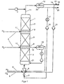
- FIG. 1 shows an example of a reactor system with the one arranged upright Reactor 1, in which several through intermediate feeds 2 layers 3 separated from hydrogen by fabric-like structures Catalyst monoliths are mounted.
- a gas-liquid distributor e.g. a mixing nozzle 6 in the circular liquid 7 in the form of bubbles distributed.
- a mixing nozzle 6 in the circular liquid 7 in the form of bubbles distributed.
- a separate mixing nozzle can be used - a partial flow 8 of the hydrogen.
- Further subsets 2 of hydrogen are volume-controlled via distribution devices 9 at the intermediate feed points 10 between the catalyst layers 3 fed in.
- the two-phase reactor discharge 11 removed and separated in a separation vessel 12.
- the gas phase is via a compressor 13 - or less Height of the reactor preferably directly - via the mixing nozzle 6 am added again at the bottom of the reactor.
- a partial stream 14 of the Gases is used to limit the enrichment of inert components led into the exhaust line 16 via a pressure maintenance 15.
- the Liquid is cooled with cooling water via a heat exchanger 17 and via the pump 18 again at the lower end of the reactor fed in.
- intermediate withdrawals 19 are also possible to provide the two-phase reactor contents along the reactor, perform a phase separation 20 and both phases - the liquid phase cooled - again at a lower point 21 of the reactor fully close.
- the liquid reaction product 22 is a partial stream 23 removed from the phase separator 12 at the upper end of the reactor.
- a corrugated and a smooth mesh made of V4A steel (1.4571, mesh size 180 ⁇ m, wire diameter 146 ⁇ m) was placed on top of each other and a cylindrical monolith with a height of 5 cm and a diameter of 5 cm also rolled. The ends the nets were fixed by welding spots.
- the network plane spacing the smooth mesh was at least 1 mm.
- the monolithic support was successively treated with acetone and distilled water and then dried.
- the monolith was then treated with a solution of 25% by weight of concentrated hydrochloric acid and 75% by weight of distilled water at 60 ° C. for 30 minutes and rinsed with distilled water.
- the monolith treated in this way was placed in 150 ml of distilled water.
- a 270 ml autoclave with stirrer and thermostat serves as the reaction vessel and pressure maintenance of 50 bar.
- this autoclave became the catalyst monolith produced in I around the stirrer axis centered installed so that it is evenly through the stirrer is supplied with liquid and gas.
- Located in the reactor floor there are supply lines for oxygen, hydrogen and the reaction medium.
- In the reactor cover there is a derivative from which the Product / gas mixture is continuously removed. After deducting the Volumes for all internals stood an effective reaction volume of 208 ml available.
- the reaction medium consisted of methanol, the 0.4% by weight sulfuric acid, 0.1% by weight phosphoric acid and 6 ppm bromide (in the form of sodium bromide) have been added. With the reaction medium the reactor flooded. Then a current of 72.8 g / h reaction medium, 48.6 l / h oxygen and 5.5 l / h hydrogen (Gases based on normal conditions) through the reactor. At the The product / gas mixture was removed continuously from the reactor lid.
- the conversion based on hydrogen was 76% (according to the determination of the hydrogen content in the exhaust gas) with a selectivity of 82%.
- the concentration of the methanolic hydrogen peroxide solution thus prepared was 7% by weight (titration with KMnO 4 0.1 N).
- H 2 O 2 was carried out under comparable conditions as in Example 1 for 1000 hours.
- a total of 2.9 kg of hydrogen peroxide was obtained as a methanolic solution with a concentration of 4% by weight.
- a catalyst monolith was produced from V4A mesh with a palladium coating. This molding was then hydrogenated at 70 ° C. and 50 bar with hydrogen, treated with methanolic H 2 O 2 solution at 20 ° C. and dried with nitrogen. The catalyst molding was then installed in the autoclave from II.
- the reaction was carried out analogously to Example 1: the reaction medium was passed through the reactor at a rate of 214.5 g / h, oxygen at 145.8 l / h and hydrogen at 16.2 l / h at 42.2 ° C. The conversion based on H 2 was 84%, with a selectivity of 75%.
- the concentration of the methanolic hydrogen peroxide solution produced was 7% by weight.
- Example 3 The same catalyst as in Example 3 was used.
- the conversion based on H 2 was 90% with a selectivity of 68%.
- the concentration of the hydrogen peroxide solution thus prepared was 2.7% by weight.
- the same catalyst as in Example 3 was used.
- the Reaction medium consisted of water, the 0.4 wt .-% sulfuric acid, 0.1% by weight phosphoric acid and 6 ppm bromide (in the form of sodium bromide) were added.
- the conversion, based on hydrogen, was made by obtained a hydrogen determination of the exhaust gas and was 43% with a selectivity of 70%.
- the concentration of the so produced Hydrogen peroxide solution was 5.6% by weight.
Abstract
Description
Die vorliegende Erfindung betrifft ein Verfahren zur Herstellung von Wasserstoffperoxid-Lösungen mit einem Wasserstoffperoxid-Gehalt von wenigstens 2,5 Gew%, durch Umsetzung von Wasserstoff und Sauerstoff nach einem kontinuierlichen Verfahren an Katalysatoren, die als aktive Komponente Palladium enthalten.The present invention relates to a method for manufacturing of hydrogen peroxide solutions with a hydrogen peroxide content of at least 2.5% by weight by reacting hydrogen and Oxygen by a continuous process on catalysts, which contain palladium as the active component.
Übliche industrielle Verfahren für die Herstellung von Wasserstoffperoxid sind die Elektrolyse saurer Ammoniumsulfatlösungen, die Oxidation von Isopropylalkohol oder das Anthrachinonverfahren. Die direkte Synthese von Wasserstoffperoxid aus den Elementen an Übergangsmetallkatalysatoren ist bekannt, hat jedoch bislang keine kommerzielle Verwendung gefunden.Common industrial processes for the production of hydrogen peroxide are the electrolysis of acidic ammonium sulfate solutions, the oxidation of isopropyl alcohol or the anthraquinone process. The direct synthesis of hydrogen peroxide from the elements of transition metal catalysts is known, but has so far no commercial use found.
Dies ist auf mehrere Gründe zurückzuführen. So bilden Wasserstoff und Sauerstoff explosive Gasgemische, wenn der Gehalt an Wasserstoff in der Gasmischung oberhalb 5 Vol.% liegt. Andererseits ist die Bildungsgeschwindigkeit von Wasserstoffperoxid bei Verwendung von Wasserstoff/Sauerstoff-Mischungen außerhalb des explosiven Bereichs in der Regel zu gering, um vernünftige Raum-Zeit-Ausbeuten zu gewährleisten. Zudem kann ein zu hoher Gehalt an Sauerstoff im Reaktionsgas den oxidativen Abbau der Katalysatoren beschleunigen.There are several reasons for this. This is how hydrogen is formed and oxygen explosive gas mixtures when the hydrogen content is above 5% by volume in the gas mixture. On the other hand the rate of formation of hydrogen peroxide when used of hydrogen / oxygen mixtures outside of the explosive Range is usually too small to achieve reasonable space-time yields to ensure. In addition, too high an oxygen content accelerate the oxidative degradation of the catalysts in the reaction gas.
Ein weiteres Problem stellt die Selektivität der Reaktion dar. So steht die Bildungsreaktion des Wasserstoffperoxids in Konkurrenz zur Bildung von Wasser. Zudem katalysieren die für die Bildung von Wasserstoffperoxid aus den Elementen geeigneten Katalysatoren auch die Abbaureaktion des Wasserstoffperoxids in Gegenwart von überschüssigem Wasserstoff entsprechend folgender Reaktionsgleichung: H2O2 + H2 → 2H2O. Dieses Selektivitätsproblem kann dadurch gelöst werden, daß man nach kontinuierlichen Verfahren mit hohen Durchflußgeschwindigkeiten arbeitet. Dies hat jedoch zur Folge, daß bei niedriger Reaktionsgeschwindigkeit die im Austrag erhaltenen Wasserstoffperoxid-Konzentrationen für eine wirtschaftliche Nutzung dieses Verfahrens zu gering werden. Außerdem treten bei zu hohen Fließgeschwindigkeiten Abrasionsprobleme am Katalysator auf, was zu verkürzten Standzeiten und damit ebenfalls zu wirtschaftlichen Nachteilen dieses Verfahrens führt. Another problem is the selectivity of the reaction. The hydrogen peroxide formation reaction competes with the formation of water. In addition, the catalysts suitable for the formation of hydrogen peroxide from the elements also catalyze the degradation reaction of the hydrogen peroxide in the presence of excess hydrogen in accordance with the following reaction equation: H 2 O 2 + H 2 → 2H 2 O. This selectivity problem can be solved by continuously Process works at high flow rates. However, this has the consequence that the hydrogen peroxide concentrations obtained in the discharge become too low for an economical use of this process at a low reaction rate. In addition, abrasion problems on the catalyst occur when the flow rates are too high, which leads to shortened downtimes and thus also to economic disadvantages of this process.
Die US-4,009,252 offenbart für die Bildung von Wasserstoffperoxid aus Wasserstoff und Sauerstoff an palladiumhaltigen Katalysatoren ein optimales Verhältnis von O2 zu H2 im Bereich von 1,5:1 bis 20:1, also im Explosivbereich. Die Umsetzung erfolgt nach dem Batchverfahren, die erreichten Raum-Zeit-Ausbeuten sind nicht zufriedenstellend.No. 4,009,252 discloses an optimal ratio of O 2 to H 2 in the range from 1.5: 1 to 20: 1, ie in the explosive range, for the formation of hydrogen peroxide from hydrogen and oxygen on palladium-containing catalysts. The reaction is carried out according to the batch process, the space-time yields achieved are not satisfactory.
Scaros et al. (eds): "Catalysis of organic reactions", 1995, Marcel Dekker Inc., New York, S. 115-124, J. Kosak, beschreibt die Umsetzung von Wasserstoff und Sauerstoff an palladium-haltigen Katalysatoren in form eines Monoliths in wässriger Lösung.Scaros et al. (eds): "Catalysis of organic reactions", 1995, Marcel Dekker Inc., New York, pp. 115-124, J. Kosak, describes the conversion of hydrogen and oxygen over palladium-containing catalysts in the form of a monolith in aqueous solution ,
Die WO 92/04277 beschreibt die Umsetzung von Wasserstoff mit Sauerstoff in einem mit wässriger Katalysatorsuspension gefüllten Rohrreaktor. Die verwendeten Gasgemische liegen vorzugsweise im Explosionsbereich. Durch eine hohe Strömungsgeschwindigkeit des Reaktionsmediums (> 1m/sek) wird gewährleistet, daß das Reaktionsgas in Form kleiner Blasen vollständig im Reaktionsmedium dispergiert ist, so daß ein explosionsartiges Abreagieren des Reaktionsgases nicht möglich ist. Die nach einmaligem Durchlauf der Reaktionszone erhaltenen Wasserstoffperoxidkonzentrationen liegen unterhalb 1 Gew%. Höhere Ausbeuten können nur durch mehrmaliges Durchlaufen der Reaktionszone erreicht werden. Als problematisch erweist sich, daß der Katalysator in Form einer Suspension verwendet wird. Dies erfordert aufwendige Filtrations- und Rückführungsmaßnahmen, wobei Katalysatorverluste unvermeidbar sind. Reaktionsrohre, die für den erforderlichen Reaktionsdruck geeignet sind - in den Beispielen werden Druckwerte oberhalb 80 bar offenbart - sind vergleichsweise teuer. Das genannte Verfahren ist daher als sehr teuer einzustufen. Ein ähnliches Verfahren mit verbesserter Verwirbelung der Wasserstoff- und Sauerstoffströme ist in der WO 96/05138 beschrieben.WO 92/04277 describes the reaction of hydrogen with oxygen in a filled with aqueous catalyst suspension Tubular reactor. The gas mixtures used are preferably in Explosion range. Due to a high flow rate of the Reaction medium (> 1m / sec) ensures that the reaction gas in the form of small bubbles completely in the reaction medium is dispersed, so that an explosive reaction of the reaction gas not possible. After a single run of the Reaction zone obtained hydrogen peroxide concentrations are below 1% by weight. Higher yields can only be achieved by repeated Pass through the reaction zone. As problematic turns out that the catalyst is used in the form of a suspension becomes. This requires complex filtration and recycling measures, where catalyst losses are inevitable. Reaction tubes, which are suitable for the required reaction pressure are - in the examples, pressure values above 80 bar are disclosed - are comparatively expensive. The above procedure is therefore classified as very expensive. A similar process with improved Swirling of the hydrogen and oxygen flows described in WO 96/05138.
Die US-A 5,500,202 und die EP-A 579 109 beschreiben ein kontinuierliches Verfahren zur Herstellung von Wasserstoffperoxid durch Umsetzung von H2/O2-Gasmischungen an einem stationären, pulverförmigen Katalysator (Teilchengrößen im Bereich von 10 µm bis 250 µm) in einem Rieselbett-Reaktor. Um das Explosionsrisiko bei dem in einem Rieselbettreaktor üblicherweise großen Gasvolumen zu verringern, wird dem Reaktionsgas Stickstoff als Inertgas zugeführt. Dies verursacht jedoch zusätzliche Kosten. Die auf diesem Wege erhaltenen wässrigen Wasserstoffperoxid-Lösungen weisen lediglich Konzentrationen im Bereich von 3 bis 5 Gew% auf. Der Umsatz bezogen auf Wasserstoff liegt lediglich im Bereich von 25 - 35%. Über die Lebensdauer des Katalysators werden keine Angaben gemacht. Wegen der starken Wärmeentwicklung werden Reaktoren mit einem maximalen. Innendurchmesser von 30 mm empfohlen. Für eine industriell e Nutzung müßten daher mehrere 1000 dieser Rohrreaktoren install iert werden, was hohe Investitionskosten mit sich bringt. US Pat. No. 5,500,202 and EP-A 579 109 describe a continuous process for producing hydrogen peroxide by reacting H 2 / O 2 gas mixtures over a stationary, powdery catalyst (particle sizes in the range from 10 μm to 250 μm) in a trickle bed -Reactor. In order to reduce the risk of explosion in the gas volume which is usually large in a trickle bed reactor, nitrogen is added to the reaction gas as an inert gas. However, this causes additional costs. The aqueous hydrogen peroxide solutions obtained in this way only have concentrations in the range from 3 to 5% by weight. The turnover based on hydrogen is only in the range of 25 - 35%. No information is given on the life of the catalyst. Because of the strong heat development, reactors with a maximum. Internal diameter of 30 mm recommended. For industrial use, several 1000 of these tubular reactors would have to be installed, which entails high investment costs.
Die US-A 4,336,238 und US-A 4,336,239 beschreiben die Umsetzung von Wasserstoff und Sauerstoff zu Wasserstoffperoxid an palladiumhaitigen Katalysatoren in organischen Lösungsmitteln oder Lösungsmittelmischungen, die gegebenenfalls auch Wasser enthalten. Durch das beschriebene Verfahren kann der Anteil an Wasserstoff im Reaktionsgas gesenkt werden, jedoch sind die erhaltenen Wasserstoffperoxidkonzentrationen von maximal 2,4 Gew% bei Verwendung von Reaktionsgasmischungen, die weniger als 5 Vol% Wasserstoff enthalten, für eine wirtschaftliche Anwendung zu gering. Die Verwendung organischer Lösungsmittel wirkt sich vorteilhaft auf die Katalysatorlebensdauer aus. Nach 285 Stunden Betriebsdauer ist die Kataysatoraktivität allerdings auf 69% des ursprünglichen Wertes gesunken, was für eine industrielle Anwendung immer noch zu gering ist. Die US-A 4,389,390 beschreibt ein ähnliches Verfahren, wobei der Katalysator, der sich vom Träger gelöst hat, durch Aktivkohlefilter zurückgewonnen wird. Ein weiterer Vorteil dieses Verfahrens ist darin zu sehen, daß durch Entfernung des Katalysators aus dem Reaktionsmedium die Neigung des Wasserstoffperoxids zur Zersetzung verringert wird. Jedoch werden im kontinuierlichen Betrieb keine Wasserstoffperoxidlösungen mit einem Gehalt oberhalb 2,1 Gew% erhalten.US-A 4,336,238 and US-A 4,336,239 describe the implementation from hydrogen and oxygen to hydrogen peroxide on palladium-containing Catalysts in organic solvents or solvent mixtures, which may also contain water. The process described can reduce the proportion of hydrogen be reduced in the reaction gas, however, the hydrogen peroxide concentrations obtained of maximum 2.4% by weight when used of reaction gas mixtures containing less than 5 vol% hydrogen included, too low for an economical application. The use of organic solvents has an advantageous effect on the catalyst life. After 285 hours of operation however, the catalyst activity is 69% of the original Declined in value, what an industrial application is still too low. US-A 4,389,390 describes a similar one Process wherein the catalyst is released from the support has been recovered by activated carbon filters. Another The advantage of this method is that removal of the catalyst from the reaction medium the tendency of Hydrogen peroxide for decomposition is reduced. However no hydrogen peroxide solutions in continuous operation obtained a content above 2.1% by weight.
Hinsichtlich des Problems der Katalysatordesaktivierung bei der Herstellung von Wasserstoffperoxid aus den Elementen finden sich in der Literatur verschiedene Lösungsvorschläge. So beschreiben die US-A 5,352,645 und die WO 92/04976 spezielle feste Träger aus sprühgetrocknetem, kolloidalen Kieselgel. Die Verwendung superazider Oxide als Trägermaterialien wird in der US 5,236,692 sowie in der EP-A 437 836 vorgeschlagen. Hierdurch kann der übliche Säureanteil des Reaktionsmediums vermieden werden. Die EP-A 627 381 lehrt die Verwendung von Niob-, Tantal-, Molybdän- oder Wolframoxiden als Trägermaterialien, die sich durch hohe Säurefestigkeit auszeichnen. Die US-A 5,292,496 beschreibt die Verwendung von Cer-haltigen Trägermaterialien, um so die Verwendung von Halogen als Stabilisator im Reaktionsmedium zu vermeiden. Die Herstellung des Wasserstoffperoxids erfolgt in den genannten Schriften jedoch immer nach Batch- oder halbkontinuierlichen Verfahren, die für eine industrielle Nutzung wenig geeignet sind. Zudem lassen die kurzen Reaktionszeiten keine Aussage über die Lebensdauer der Katalysatoren zu.Regarding the problem of catalyst deactivation in the Production of hydrogen peroxide from the elements can be found various suggested solutions in the literature. Describe like this US-A 5,352,645 and WO 92/04976 special solid supports spray-dried colloidal silica gel. The use of superacid Oxides as carrier materials is described in US 5,236,692 as well proposed in EP-A 437 836. This allows the usual Acid content of the reaction medium can be avoided. EP-A 627 381 teaches the use of niobium, tantalum, molybdenum or tungsten oxides as carrier materials, which are characterized by high acid resistance distinguished. US-A 5,292,496 describes the use of cerium-containing carrier materials, so as to use Avoid halogen as a stabilizer in the reaction medium. The Production of the hydrogen peroxide takes place in the above However, fonts always use batch or semi-continuous processes, which are not very suitable for industrial use. In addition, the short reaction times leave no statement about the Catalyst life too.
Die Verwendung von Katalysatormonolithen, die als aktive Komponente Palladium enthalten, wird von Kosak in "Catalysis of Organic Reactions (Scaros und Prunier, Hrsg.), Marcel Dekker Inc., New York 1995, S. 115ff, für die Herstellung von Wasserstoffperoxid aus den Elementen beschrieben. Die Umsetzung erfolgt diskontinuierlich in einem wässrigen Reaktionsmedium bei einem vergleichsweise hohen Druck von 144 bar und einem moalren Verhaltnis von O2:H2 = 4,7, also im Explosionsbereich.The use of catalyst monoliths containing palladium as the active component is described by Kosak in "Catalysis of Organic Reactions (Scaros and Prunier, ed.), Marcel Dekker Inc., New York 1995, p. 115ff. For the production of hydrogen peroxide from the The reaction is carried out batchwise in an aqueous reaction medium at a comparatively high pressure of 144 bar and a moderate ratio of O 2 : H 2 = 4.7, ie in the explosion range.
Der vorliegenden Erfindung liegt die Aufgabe zugrunde, ein Verfahren für die Herstellung von Wasserstoffperoxid aus Wasserstoff und Sauerstoff bereitzustellen, das es auch bei Verwendung von Wasserstoff/Sauerstoff-Mischungen außerhalb des Explosiv-Bereiches (O2:H2>20:1) erlaubt, Wasserstoffperoxid-Lösungen mit einem Gehalt oberhalb 2,5 Gew% herzustellen. Die verwendeten Katalysatoren sollen hohe Standzeiten aufweisen.It is the object of the present invention to provide a process for the production of hydrogen peroxide from hydrogen and oxygen which also allows the use of hydrogen / oxygen mixtures outside the explosive range (O 2 : H 2 > 20: 1), To produce hydrogen peroxide solutions with a content above 2.5% by weight. The catalysts used should have a long service life.
Diese Aufgabe konnte gelöst werden durch ein kontinuierliches Verfahren, das die Umsetzung von Wasserstoff und Sauerstoff in Wasser und/oder C1-C3-Alkanolen als Reaktionsmedium an Katalysatorformkörpern, die als aktive Komponente Palladium enthalten, umfaßt.This object was achieved by a continuous process which comprises the reaction of hydrogen and oxygen in water and / or C 1 -C 3 -alkanols as the reaction medium on shaped catalyst bodies which contain palladium as the active component.
Die vorliegende Erfindung betrifft somit ein Verfahren zur Herstellung von Wasserstoffperoxid-Lösungen mit einem Wasserstoffperoxid-Gehalt von wenigstens 2,5 Gew%, durch kontinuierliche Umsetzung von Wasserstoff und Sauerstoff an Katalysatoren, die als aktive Komponente Palladium enthalten, das dadurch gekennzeichnet ist, daß die Umsetzung in Wasser und/oder C1-C3-Alkanolen als Reaktionsmedium an Katalysatorformkörpern in Form geordneter, in den Reaktor eingebauter Katalysatoren erfolgt, wobei das Reaktionsgas, enthaltend Sauerstoff und Wasserstoff, im Gleichstrom mit der flüssigen Reaktionsphase durch den Reaktor geführt wird.The present invention thus relates to a process for the preparation of hydrogen peroxide solutions with a hydrogen peroxide content of at least 2.5% by weight, by continuous reaction of hydrogen and oxygen over catalysts which contain palladium as the active component, which is characterized in that the Reaction in water and / or C 1 -C 3 -alkanols as the reaction medium takes place on shaped catalyst bodies in the form of ordered catalysts installed in the reactor, the reaction gas containing oxygen and hydrogen being passed through the reactor in cocurrent with the liquid reaction phase.
Unter Katalysatorformkörpern sind Katalysatoren zu verstehen, bei denen die katalytisch aktive Komponente sich auf der Oberfläche speziell geformter Träger befindet. Derartige Träger können übliche Füllkörper, wie Raschig-Ringe, Sattelkörper, Pall@-Ringe, Drahtspiralen oder Maschendrahtringe sein, die aus unterschiedlichen Materialien, die sich für eine Beschichtung mit der aktiven Komponente eignen (siehe auch Römpp-Chemie-Lexikon, 9. Aufl., S. 1453f.) aufgebaut sind. Die mit der katalytisch aktiven Komponente versehenen Füllkörper werden als lose Schüttung in den Reaktor gegeben. Bevorzugte Formkörper weisen Kanäle mit hydraulischen Radien (Definition siehe VDI-Wärmeatlas, Abschnitt LE1) im Bereich von 1 bis 10 mm auf.Shaped catalyst bodies are to be understood as catalysts, at which the catalytically active component is on the surface specially shaped carrier. Such carriers can be conventional Packings, such as Raschig rings, saddle bodies, Pall @ rings, Wire spirals or wire mesh rings that are made of different Materials that are suitable for a coating with the active Components are suitable (see also Römpp-Chemie-Lexikon, 9th edition, p. 1453f.). The one with the catalytically active component Provided packing is in the reactor as a loose bed given. Preferred moldings have channels with hydraulic Radii (for definition see VDI Heat Atlas, section LE1) in Range from 1 to 10 mm.
Erfindungsgemäß werden Katalysatorformkörper, die in Form geordneter Packungen in den Reaktor eingebaut werden und die aufgrund einer Vielzahl von Durchströmungskanälen eine große Oberfläche, bezogen auf ihr Volumen, aufweisen, verwendet. Derartige Formkörper werden im folgenden als Katalysatormonolithe bezeichnet. Geeignete Reaktoren sind beispielsweise in den EP-A 068 862, EP-A 201 614 und der EP-A 448 884 beschrieben. According to the invention, shaped catalyst bodies are more ordered in shape Packs are installed in the reactor and due to a Large number of flow channels covering a large surface area on their volume, have used. Such moldings are in the following referred to as catalyst monoliths. Suitable reactors are for example in EP-A 068 862, EP-A 201 614 and EP-A 448 884.
Die Katalysatormonolithe bzw. die monolithischen Träger sind in der Regel aus Geweben, Gestricken, Folien, Streckmetallen und/oder Blechen aufgebaut. Monolitische Träger können auch, wie in der US-A 4,364,888 und der US-A 4,333,896 beschrieben, durch Extrusion hergestellt werden. Als monolithische Träger sind auch Formkörper geeignet, die aus offenzelligen Schäumen aufgebaut sind. Diese Schäume können beispielsweise aus Keramik, Melaminharzen oder Polyurethan bestehen.The catalyst monoliths or the monolithic supports are in usually from fabrics, knitted fabrics, foils, expanded metals and / or Sheets built up. Monolithic supports can also, as in U.S. 4,364,888 and U.S. 4,333,896 Extrusion. As monolithic supports too Shaped body suitable, which is built from open-cell foams are. These foams can be made of ceramic, melamine resins, for example or polyurethane.
Bevorzugt werden Katalysatormonolithe, die aus Geweben aufgebaut sind, da diese im Reaktor vom flüssigen Reaktionsmedium besonders gut durchströmt werden und somit hohe Umsatzgeschwindigkeiten ermöglichen.Preference is given to catalyst monoliths built up from fabrics are special because they are in the reactor of the liquid reaction medium flow well and thus enable high sales speeds.
Geeignete Gewebe sind beispielsweise aus Fasern oxidischer Materialien, wie Al2O3 und/oder SiO2, oder aus Kunststoffasern, wie z.B. Polyamid-, Polyester-, Polyvinylchlorid-, Polyethylen-, Polypropylen-, Polytetraflurethylenfasern oder Kohlefasern aufgebaut. Bevorzugt werden gewebeförmige Katalysatorträger, die aus webbaren Metalldrähten, beispielsweise aus Eisen, Federstahl, Hastelloy, Monel, Silber, Chromstahl, Chromnickelstahl oder Titan, aufgebaut sind. Ganz besonders bevorzugt werden gewebeförmige Katalysatorträger, die aus webbaren Drähten hochlegierter Edelstähle oder Metalle, die sich durch Ausbildung einer Passivierungsschicht vor weiterer Korrosion schützen, aufgebaut sind, beispielsweise Cr-Stähle, CrNi-Stähle, CrNiTi-Stähle und CrNiMo-Stähle oder hitzebeständige Stähle mit den Werkstoffnummern 1.4016, 1.4767, 1,4401, 2.4610, 1.4765, 1.4847, 1.4301, 1.4742.Suitable fabrics are constructed, for example, from fibers of oxidic materials, such as Al 2 O 3 and / or SiO 2 , or from plastic fibers, such as, for example, polyamide, polyester, polyvinyl chloride, polyethylene, polypropylene, polytetraflurethylene fibers or carbon fibers. Preference is given to fabric-shaped catalyst supports which are constructed from weavable metal wires, for example from iron, spring steel, Hastelloy, Monel, silver, chromium steel, chromium-nickel steel or titanium. Tissue-shaped catalyst carriers are particularly preferred, which are made from weave wires of high-alloy stainless steels or metals that protect themselves from further corrosion by forming a passivation layer, for example Cr steels, CrNi steels, CrNiTi steels and CrNiMo steels or heat-resistant steels material numbers 1.4016, 1.4767, 1.4401, 2.4610, 1.4765, 1.4847, 1.4301, 1.4742.
Aus den genannten Drähten und Fasern lassen sich Gewebe unterschiedlicher Webart herstellen, wie glatte Gewebe, Köpergewebe, Tressengewebe, Fünfschaft-Atlas-Gewebe und andere Spezialbindungsgewebe. Bevorzugt werden diese Gewebe zu mehrlagigen Gewebeverbänden zusammengefasst. Geeignete gewebeförmige, monolithische Katalysatorträger sind in der EP-A 498 435 beschrieben.Fabrics can be made differently from the wires and fibers mentioned Manufacture weave, such as smooth fabrics, twill fabrics, Braid fabrics, five-shaft atlas fabrics and other special weaves. These fabrics are preferred to form multi-layered tissue associations summarized. Suitable tissue-shaped, monolithic Catalyst supports are described in EP-A 498 435.
Besonders geeignete Katalysatormonolithe sind aus mehreren Lagen gewellter, geknickter und/oder glatter Gewebe aufgebaut, die so angeordnet sind, daß benachbarte Lagen mehr oder weniger abgeschlossene Kanäle bilden. Der hydraulische Durchmesser der Kanäle liegt vorzugsweise im Bereich von 1 bis 10 mm, insbesondere von 1,5 bis 3 mm (gemäß Definition in VDI-Wärmeatlas, Abschnitt LE1). Diese Kanäle können gerade oder gebogen sein. Bevorzugt werden mehrlagige Gewebe, in denen sich glatte und gewellte bzw. geknickte Gewebe abwechseln. Monolithe, in denen die Gewebe teilweise oder vollständig durch Bleche, Gestricke oder Streckmetalle ersetzt sind, können ebenfalls verwendet werden. Derartige Monolithe werden bevorzugt so in den Reaktor eingebaut, daß die Kanäle gegen die Durchströmungsrichtung des Reaktionsmediums geneigt sind. Die Gewebelagen selber werden vorzugsweise parallel zur Strömungsrichtung im Reaktor eingebaut. Sind mehrere dieser Baueinheiten nacheinander geschaltet, erfolgt ihr Einbau vorzugsweise so, daß die Durchströmungskanäle gegen die Strömungsrichtung alternierend in entgegengesetzte Richtungen geneigt sind. Die Baueinheiten werden vorzugsweise so eingebaut, daß die Gewebelagen zweier aufeinanderfolgender Baueinheiten einen Winkel von vorzugsweise etwa 90° zueinander einnehmen. Wickelmodule aus gewellten oder geknickten und gegebenenfalls auch ebenen Gewebelagen sind ebenfalls geeignet.Particularly suitable catalyst monoliths consist of several layers corrugated, kinked and / or smooth fabric built up like that are arranged that adjacent layers more or less closed Form channels. The hydraulic diameter of the channels is preferably in the range from 1 to 10 mm, in particular from 1.5 to 3 mm (as defined in VDI Heat Atlas, section LE1). These channels can be straight or curved. To be favoured multi-layer fabrics in which there are smooth and wavy or kinked Alternate tissues. Monoliths in which the tissues partially or entirely through sheet metal, knitted fabric or expanded metal can also be used. Such monoliths are preferably installed in the reactor so that the channels inclined against the flow direction of the reaction medium are. The fabric layers themselves are preferably parallel built into the flow direction in the reactor. Are several of these Units connected in series, they are preferably installed so that the flow channels against the flow direction are alternately inclined in opposite directions. The units are preferably installed so that the fabric layers two consecutive units an angle of preferably take about 90 ° to each other. Corrugated winding modules or kinked and possibly also flat fabric layers are also suitable.
Die Beschichtung der Katalysatorträger mit der katalytisch aktiven Komponente erfolgt nach den für sie üblichen Methoden (s.u.). Bei monolithischen Trägern, die aus Geweben, Folien, Blechen, Gestricken oder Streckmetallen aufgebaut sind, erfolgt die Beschichtung in der Regel vor der Weiterverarbeitung zum Katalysatormonolithen. Sie kann jedoch auch am vorgeformten Träger erfolgen. Sollen die Gewebe in Einsatzrahmen gespannt und gegebenenfalls anschliessend zu Katalysatorzellen zusammengefügt werden, empfiehlt es sich, die Beschichtung der Gewebe im nichtverarbeiteten Zustand vorzunehmen.The coating of the catalyst carrier with the catalytically active Components are made using the methods that are customary for them (see below). In the case of monolithic supports made from fabrics, foils, sheets, and knitted fabrics or expanded metals are built up, the coating takes place usually before further processing to the catalyst monolith. However, it can also be carried out on the preformed carrier. Should the fabrics be stretched in insert frames and if necessary are then combined into catalyst cells, it is recommended to coat the fabric in the unprocessed Condition.
Die katalytisch aktive Komponente kann neben Palladium als Hauptbestandteil weitere Metalle, vorzugsweise Edelmetalle und insbesondere Platin, Rhodium, Iridium, Kupfer, Silber und/oder Gold als Promotoren enthalten. Das Verhältnis Palladium/Promotormetall liegt vorzugsweise im Bereich von 100:1 bis 1:10 und insbesondere im Bereich von 10:1 bis 1:1. Das Palladium sowie die gegebenenfalls anwesenden Promotormetalle machen in der Regel 5 x 10⁻⁴ bis bis 1 Gew% und insbesondere 10-3 bis 0,15 Gew% bezogen auf die gesamte Katalysatormasse (Träger + aktive Komponente) aus.In addition to palladium, the catalytically active component can contain further metals, preferably noble metals and in particular platinum, rhodium, iridium, copper, silver and / or gold as promoters. The ratio of palladium / promoter metal is preferably in the range from 100: 1 to 1:10 and in particular in the range from 10: 1 to 1: 1. The palladium and any promoter metals that are present usually make up 5 × 10 -4 to 1% by weight and in particular 10 -3 to 0.15% by weight, based on the total catalyst mass (support + active component).
Bei Katalysatorträgern mit poröser Oberfläche, wie sie beispielsweise Katalysatorträger mit Oberflächen aus aktivem Aluminiumoxid oder SiO2 aufweisen, wird die aktive Komponente in der Regel durch einen Imprägnierung- oder Tränkungsschritt, dem in der Regel ein Trocknungs- und Aktivierungsschritt folgt, aufgebracht. Derartige Techniken sind beispielsweise in der DE-A 22 56 195 oder in der DE-A 23 17 560 beschrieben, auf die hier in vollem Umfang Bezug genommen wird. Ebenfalls geeignet sind Katalysatoren, bei denen auf einem Metallträger eine aktive Aluminiumoxidschicht und anschließend ein Überzug aus Palladium aufgebracht wird. Die Oxidschicht wird durch Tauchen des Trägers in eine Dispersion aus aktivem Aluminiumoxid und anschließender Temperung bei erhöhter Temperatur hergestellt. Auf diese Oxidschicht wird anschließend durch Tränken mit einer Palladiumsalzlösung das Edelmetall aufgebracht und dieses nach Trocknung durch Reduktion mit Wasserstoff bei 500°C aktiviert. Dieses Verfahren ist in der EP-A 075 124 offenbart, auf die hier ebenfalls in vollem Umfang Bezug genommen wird. Die DE-A 41 13 525 beschreibt ein Verfahren zur Beschichtung von Oberflächen in komplexen geometrischen Gebilden mit Edelmetallen, indem man in einem ersten Schritt die Gebilde mit einer Lösung, die Komplexe der Metalle mit organischen Liganden enthält, benetzt und anschließend diese Komplexe durch UV-Bestrahlung zerstört. Auf diese Weise lassen sich Netze, Fliese, Fasern, Körper mit wabenförmiger, schwammartiger oder poröser Struktur, unabhängig von der chemischen Beschaffenheit der Oberfläche, mit stabilen Edelmetallbeschichtungen versehen. Auch dieses Beschichtungsverfahren ist für die Herstellung der erfindungsgemäßen Katalysatormonolithe geeignet. Erfindungsgemäß geeignete Beschichtungen lassen sich auf die in der EP-A 374 099 beschriebene Weise durch Tränken des Katalysatorträgers mit geeigneten Palladium(0)komplexen und anschließende Thermolyse dieser Komplexe erhalten. Reetz et al. (Angew. Chem. 1995, 107, 2956-2958) beschreibt die Beschichtung von SiO2- oder Al2O3-Oberflächen mit präformierten Palladiumclustern. Auf diese Weise werden auch bei porösen Oberflächen sehr dünne Schichten der aktiven Komponente (Eggshell-Katalysatoren), erhalten. Auch auf diese Weise sind erfindungsgemäß geeignete Katalysatormonolithe herstellbar. Das Aufbringen von Metallen auf thermisch stabile Katalysatorträger kann auch nach dem Verfahren des Flammspritzens erfolgen (s. P. Fauchais et al. in Pure and Appl. Chem., Vol. 66, 1994, 1247-1258). Das Aufbringen der katalytisch aktiven Komponente kann auch durch Aufdampfen von Metallen auf den Katalysatorträger im Vakuum erfolgen. Als Vakuumverdampfungstechniken kommen insbesondere die thermische Verdampfung, die Flash-Verdampfung, die Kathodenzerstäubung sowie Sputtern in Frage. Die thermische Verdampfung kann durch direkte oder indirekte elektrische Heizung erfolgen. Vorzugsweise benutzt man die Elektronenstrahlverdampfung für diese Methode. Die erfindungsgemäßen, gewebeförmigen Katalysatorträger können nach diesen Verfahren kontinuierlich oder diskontinuierlich beschichtet werden. Wegen weiterer Details wird auf die EP-A 198 435 verwiesen. Das in der DE-A 41 21 418 beschriebene Verfahren zum Aufbringen von Pd- oder Pt-Legierungen auf Metalloberflächen ist für die Herstellung der erfindungsgemäßen Katalysatoren ebenfalls geeignet.In the case of catalyst supports with a porous surface, such as, for example, catalyst supports with surfaces made of active aluminum oxide or SiO 2 , the active component is generally applied by an impregnation or impregnation step, which is generally followed by a drying and activation step. Such techniques are described for example in DE-A 22 56 195 or in DE-A 23 17 560, to which reference is made in full here. Catalysts are also suitable, in which an active aluminum oxide layer and then a coating of palladium are applied to a metal support. The oxide layer is produced by immersing the carrier in a dispersion of active aluminum oxide and subsequent tempering at an elevated temperature. The noble metal is then applied to this oxide layer by impregnation with a palladium salt solution and activated after drying by reduction with hydrogen at 500 ° C. This method is disclosed in EP-A 075 124, to which reference is also made in full here. DE-A 41 13 525 describes a method for coating surfaces in complex geometric structures with noble metals, in a first step by wetting the structures with a solution which contains complexes of the metals with organic ligands and then these complexes by UV Irradiation destroyed. In this way, nets, tiles, fibers, bodies with a honeycomb, sponge-like or porous structure can be provided with stable noble metal coatings, regardless of the chemical nature of the surface. This coating process is also suitable for the production of the catalyst monoliths according to the invention. Coatings suitable according to the invention can be obtained in the manner described in EP-A 374 099 by impregnating the catalyst support with suitable palladium (0) complexes and subsequent thermolysis of these complexes. Reetz et al. (Angew. Chem. 1995, 107, 2956-2958) describes the coating of SiO 2 or Al 2 O 3 surfaces with preformed palladium clusters. In this way, very thin layers of the active component (Eggshell catalysts) are obtained even on porous surfaces. Catalyst monoliths suitable according to the invention can also be produced in this way. Metals can also be applied to thermally stable catalyst supports by the flame spraying process (see P. Fauchais et al. In Pure and Appl. Chem., Vol. 66, 1994, 1247-1258). The catalytically active component can also be applied by evaporating metals onto the catalyst support in vacuo. Vacuum evaporation techniques include thermal evaporation, flash evaporation, cathode sputtering and sputtering. The thermal evaporation can be done by direct or indirect electrical heating. Electron beam evaporation is preferably used for this method. The fabric-shaped catalyst supports according to the invention can be coated continuously or batchwise by these processes. For further details, reference is made to EP-A 198 435. The process described in DE-A 41 21 418 for applying Pd or Pt alloys to metal surfaces is also suitable for the preparation of the catalysts according to the invention.
Vorzugsweise werden Palladium sowie gegebenenfalls die Promotoren durch elektrolytische, insbesondere durch elektrochemische Abscheidimg aus entsprechenden Metallsalz-Lösungen auf den Katalysatorträger aufgebracht. Als Reduktionsmittel eignen sich insbesondere Hydrazin, Zitronensäure, Ethanol, Salze der hypophosphorigen Säure, z.B. NaH2PO2, Formaldehyd, Ameisensäure, Boranate wie Natriumborhydrid, oder stabilisierte Boranlösungen wie z.B. Komplexe des Borans mit Diethylether, Diethylamin oder Diethylamin (s. auch A. Laus in Mater. Sci.Eng. A 146 (1991) 33,49; s. auch Dechema-Tagungsbericht XXIX. Jahrestreffen deutscher Katalytiker, Friedrichroda, März 1996, S. 66).Palladium and optionally the promoters are preferably applied to the catalyst support by electrolytic, in particular by electrochemical, deposition from corresponding metal salt solutions. Particularly suitable reducing agents are hydrazine, citric acid, ethanol, salts of hypophosphorous acid, for example NaH 2 PO 2 , formaldehyde, formic acid, boranates such as sodium borohydride, or stabilized borane solutions such as complexes of borane with diethyl ether, diethylamine or diethylamine (see also A. Laus in Mater. Sci.Eng. A 146 (1991) 33.49; see also Dechema conference report XXIXth annual meeting of German catalytic experts, Friedrichroda, March 1996, p. 66).
Hierbei empfiehlt es sich, den Katalysatorträger vorzubehandeln, um die Haftung der aktiven Komponente auf der Trägeroberfläche zu verbessern. Hierzu zählen beispielsweise die Entfernung von Fetten oder ähnlichen Substanzen, die die gewünschte Oberflächenhaftung behindern, beispielsweise durch Spülen mit organischen Lösungsmitteln wie Ether, Aceton oder Halogenkohlenwasserstoffen, oder das Glühen. Oxidschichten auf metallischen Trägern können auch durch Behandlung mit Mineralsäuren, z.B. Salzsäure oder Schwefelsäure, entfernt werden. Durch das hierbei erzielte "Aufrauhen" der metallischen Oberfläche wird die Zementierung der Aktivkomponente, insbesondere bei elektrolytischer oder elektrochemischer Abscheidung, verbessert.It is advisable to pretreat the catalyst carrier, to ensure the adhesion of the active component to the carrier surface improve. This includes, for example, the removal of fats or similar substances that have the desired surface adhesion hinder, for example by rinsing with organic solvents such as ether, acetone or halogenated hydrocarbons, or the glow. Oxide layers on metallic supports can also by treatment with mineral acids, e.g. Hydrochloric acid or Sulfuric acid. Through the "roughening" achieved the metallic surface becomes the cementation of the active component, especially with electrolytic or electrochemical Separation, improved.
Die durch die beschriebenen Verfahren erhaltenen Katalysatorsysteme aus Träger und Aktivkomponente/Promotoren können anschließend durch thermische Behandlung bei Temperaturen von 200 bis 900°C, vorzugsweise 400 bis 700°C, formiert werden. Diese thermische Nachbehandlung kann sowohl in oxidierender, inerter oder auch reduzierender Atmosphäre ablaufen. Besonders bei polymetallischen Systemen wird eine Formierung in reduzierender Atmosphäre bevorzugt, da hierbei leichter Legierungen ausgebildet werden.The catalyst systems obtained by the processes described from carrier and active component / promoters can then by thermal treatment at temperatures from 200 to 900 ° C, preferably 400 to 700 ° C, are formed. This thermal Aftertreatment can be in oxidizing, inert or also run in a reducing atmosphere. Especially with polymetallic Systems becomes formation in a reducing atmosphere preferred, since lighter alloys are formed.
Die fertigen Katalysatorsysteme werden dann im Reaktionsraum fixiert eingebaut (s.o.). Besonders bevorzugt werden Rohrreaktoren, in denen zylindrisch aufgebaute Katalysatoreinheiten eingepaßt sind, da sich hier eine gleichmäßige Strömung ausbilden kann, was eine besonders gute Reaktionsführung erlaubt.The finished catalyst systems are then fixed in the reaction space installed (see above). Tube reactors are particularly preferred, in which cylindrical catalyst units are fitted because there can be a steady flow, what particularly good reaction management allowed.
Die Durchführung der Reaktion erfolgt in der Regel bei geflutetem Reaktor. Als Reaktionsmedium dient Wasser und/oder C1-C3-Alkanole, vorzugsweise Wasser und/oder Methanol. Wenn als Reaktionsmedium Wasser verwendet wird, kann diesem bis zu 20 Gew.-% des Alkohols, vorzugsweise Methanol, zugesetzt werden. Wird ein alkoholisches Reaktionsmedium eingesetzt, kann dieses zu 40 Gew%, vorzugsweise bis zu 20 Gew% und besonders bevorzugt bis zu 5 Gew% Wasser enthalten. Ganz besonders bevorzugt wird Wasser als alleiniges Reaktionsmedium verwendet. Zur Stabilisierung des Wasserstoffperoxids gegen Zersetzung werden dem Reaktionsmedium Säuren, deren pKa-Wert vorzugsweise kleiner als der der Essigsäure ist, insbesondere Mineralsäuren wie Schwefelsäure, Phosphorsäure oder Salzsäure, zugesetzt. Die Säurekonzentration beträgt in der Regel wenigstens 10-4 Mol/Liter, vorzugsweise 10-3 bis 10-1 Mol/Liter. Weiterhin werden in der Regel noch Spuren von Bromid oder Chlorid in Konzentrationen von 1 bis 1000 ppm, vorzugsweise 5 bis 300 ppm zugesetzt. Es können aber auch andere Stabilisatoren, wie z.B. Formaldehyd verwendet werden.The reaction is usually carried out with the reactor flooded. Water and / or C 1 -C 3 -alkanols, preferably water and / or methanol, serve as the reaction medium. If water is used as the reaction medium, up to 20% by weight of the alcohol, preferably methanol, can be added to it. If an alcoholic reaction medium is used, it can contain 40% by weight, preferably up to 20% by weight and particularly preferably up to 5% by weight of water. Water is very particularly preferably used as the sole reaction medium. To stabilize the hydrogen peroxide against decomposition, acids, the pKa value of which is preferably less than that of acetic acid, in particular mineral acids such as sulfuric acid, phosphoric acid or hydrochloric acid, are added to the reaction medium. The acid concentration is usually at least 10 -4 mol / liter, preferably 10 -3 to 10 -1 mol / liter. Furthermore, traces of bromide or chloride are generally added in concentrations of 1 to 1000 ppm, preferably 5 to 300 ppm. However, other stabilizers such as formaldehyde can also be used.
Das Reaktionsgas, das neben Wasserstoff und Sauerstoff auch noch inerte Gase wie Stickstoff oder Edelgase enthalten kann, weist in der Regel O2:H2-Verhältnisse im Bereich von 2:1 bis 1000:1 auf. Bevorzugt werden Molverhältnisse im Bereich von 5:1 bis 100:1 und besonders bevorzugt im Bereich von 20:1 bis 50:1. Der im Reaktionsgas verwendete Sauerstoff kann auch in Form von Luft dem Reaktionsgas zugemischt werden.The reaction gas, which in addition to hydrogen and oxygen can also contain inert gases such as nitrogen or noble gases, generally has O 2 : H 2 ratios in the range from 2: 1 to 1000: 1. Molar ratios in the range from 5: 1 to 100: 1 are preferred and particularly preferably in the range from 20: 1 to 50: 1. The oxygen used in the reaction gas can also be added to the reaction gas in the form of air.
In einer bevorzugten Ausführungsform wird das Reaktionsgas im Kreis geführt. In diesem Fall liegt das Molverhältnis im Frischgasgemisch in der Nähe der Stöchiometrie, vorzugsweise im Bereich von 1,5:1 bis 0,5:1. Das Molverhältnis O2:H2 im Kreisgas sollte im Bereich von 5:1 bis 1000:1, vorzugsweise im Bereich von 20:1 bis 100:1 liegen. Die Reaktion kann bei Normaldruck als auch bei Überdrucken bis zu 200 bar durchgeführt werden. Vorzugsweise beträgt der Druck 10 bis 100 bar, insbesondere 10 bis 80 bar. Die Reaktionstempertur kann im Bereich von 0 bis 60°C liegen, vorzugsweise wird im Bereich von 20 bis 50°C gearbeitet. Vorzugsweise werden die Partialdrücke der Reaktionsgase in der Reaktionsgasmischung im Reaktor als auch im Kreisgas so gewählt, daß unter Reaktionsbedingungen die Wasserstoffkonzentration sich unterhalb der unteren Explosionsgrenze befindet.In a preferred embodiment, the reaction gas is circulated. In this case, the molar ratio in the fresh gas mixture is close to the stoichiometry, preferably in the range from 1.5: 1 to 0.5: 1. The molar ratio O 2 : H 2 in the cycle gas should be in the range from 5: 1 to 1000: 1, preferably in the range from 20: 1 to 100: 1. The reaction can be carried out at normal pressure and also under excess pressure up to 200 bar. The pressure is preferably 10 to 100 bar, in particular 10 to 80 bar. The reaction temperature can be in the range from 0 to 60 ° C, preferably in the range from 20 to 50 ° C. The partial pressures of the reaction gases in the reaction gas mixture in the reactor and in the circulating gas are preferably selected such that the hydrogen concentration is below the lower explosion limit under reaction conditions.
Reaktionsgas und Reaktionsmedium werden im Gleichstrom zueinander geführt, wöbei vorzugsweise die flussige Phase die kontinuierliche und das Reaktionsgas die diskontinuierliche Phase bildet. Bei dem bevorzugten vertikalen Reaktoraufbau (stehender Reaktor) werden Reaktionsgas und Reaktionsmedium vorzugsweise im Gleichstrom von unten nach oben durch den Reaktor geführt. Hierbei kann Wasserstoff über ein oder mehrere Zwischeneinspeisungen stromabwärts vom Einspeisungspunkt des Sauerstoffs oder der-Luft dem Reaktor zugeführt werden. Die Leerrohrgeschwindigkeit von Reaktionsgas und Reaktionsmedium liegt im Bereich von 50 bis 1000 m/h, vorzugsweise im Bereich von 150 bis 300 m/h. Reaction gas and reaction medium are in cocurrent led to each other, preferably the liquid phase, the continuous gas and the reaction gas forms the discontinuous phase. With the preferred vertical reactor structure (standing reactor) become reaction gas and reaction medium preferably in cocurrent from the bottom to passed through the top of the reactor. Here, hydrogen can have a or several intermediate feeds downstream from the feed point of oxygen or air are fed to the reactor. The empty tube speed of reaction gas and reaction medium is in the range of 50 to 1000 m / h, preferably in the range of 150 to 300 m / h.
Durch das beschriebene Verfahren lassen sich Wasserstoffperoxidlösungen mit Wasserstoffgehalten oberhalb 2,5 Gew%, vorzugsweise im Bereich von 5 bis 25 Gew% herstellen. Die Konzentration kann durch Einstellung der Stoffströme in der gewünschten Weise voralwählt werden. Die Selektivität der Wasserstoffperoxidbildung liegt dabei stets oberhalb 65%, vorzugsweise ≥ 75%. Langzeituntersuchungen haben gezeigt, daß auch nach mehr als 40 Tagen Betriebsdauer keine oder nur eine geringfügige Abnahme der Katalysatoraktivität und Selektivität zu verzeichnen ist.The described process can be used to generate hydrogen peroxide solutions with hydrogen contents above 2.5% by weight, preferably produce in the range of 5 to 25% by weight. The concentration can by preselecting the material flows in the desired manner become. The selectivity of hydrogen peroxide formation is always above 65%, preferably ≥ 75%. Long-term studies have shown that even after more than 40 days of operation little or no decrease in catalyst activity and selectivity is evident.
Weitere Einzelheiten sind in den Ansprüchen zu sehen.Further details can be seen in the claims.
Figur 1 zeigt beispielhaft ein Reaktorsystem mit dem stehend angeordneten
Reaktor 1, in dem mehrere durch Zwischeneinspeisungen
2 von Wasserstoff getrennte Schichten 3 von gewebeförmig aufgebauten
Katalysatormonolithen montiert sind. Über die Pumpe 4 wird
Methanol und/oder Wasser zugeführt. Über die Anschlußleitung 5
wird Sauerstoff zugefahren und mit einem Gas-Flüssig-Verteiler,
z.B. einer Mischdüse 6, in der Kreisflüssigkeit 7 blasenförmig
verteilt. In der gleichen Mischdüse 6 - gegebenenfalls kann auch
eine separate Mischdüse verwendet werden - wird ein Teilstrom 8
des Wasserstoffs zugefahren. Weitere Teilmengen 2 an Wasserstoff
werden mengengeregelt über Verteilereinrichtungen 9 an den Zwischeneinspeisungsstellen
10 zwischen den Katalysatorschichten 3
zugefahren. Am oberen Ende des Reaktors wird der zweiphasige Reaktoraustrag
11 entnommen und in einem Trenngefäß 12 getrennt.
Die Gasphase wird über einen Verdichter 13 - oder bei geringer
Bauhöhe des Reaktors bevorzugt direkt - über die Mischdüse 6 am
unteren Ende des Reaktors wieder zugegeben. Ein Teilstrom 14 des
Gases wird zur Begrenzung der Anreicherung von Inertbestandteilen
über eine Druckhaltung 15 in die Abgasleitung 16 geführt. Die
Flüssigkeit wird über einen Wärmetauscher 17 mit Kühlwasser gekühlt
und über die Pumpe 18 wieder am unteren Ende des Reaktors
zugefahren. Zusätzlich ist es auch möglich, Zwischenentnahmen 19
des zweiphasigen Reaktorinhalts längs des Reaktors vorzusehen,
eine Phasentrennung 20 durchzuführen und beide Phasen - die Flüssigphase
gekühlt - wieder an einer tieferen Stelle 21 des Reaktors
zuzufahren. Das flüssige Reaktionsprodukt 22 wird als Teilstrom
23 dem Phasenscheider 12 am oberen Ende des Reaktors entnommen.FIG. 1 shows an example of a reactor system with the one arranged
Die vorliegende Erfindung wird durch die folgenden Beispiele erläutert, ohne sie jedoch einzuschränken.The present invention is illustrated by the following examples, but without restricting them.
Ein gewelltes und ein glattes Netz aus V4A-Stahl (1.4571, Maschenweite 180 µm, Drahtdurchmesser 146 µm) wurde aufeinander gelegt und zu einem zylinderförmigen Monolith mit einer Höhe von 5 cm und einem Durchmesser von ebenfalls 5 cm gerollt. Die Enden der Netze wurden durch Schweißpunkte fixiert. Der Netzebenenabstand der glatten Netze betrug wenigstens 1 mm.A corrugated and a smooth mesh made of V4A steel (1.4571, mesh size 180 µm, wire diameter 146 µm) was placed on top of each other and a cylindrical monolith with a height of 5 cm and a diameter of 5 cm also rolled. The ends the nets were fixed by welding spots. The network plane spacing the smooth mesh was at least 1 mm.
Der monolithische Träger wurde sukzessive mit Aceton und destilliertem Wasser behandelt und anschließend getrocknet. Danach wurde der Monolith mit einer Lösung aus 25 Gew% konzentrierter Salzsäure und 75 Gew% destilliertem Wasser 30 Minuten bei 60°C behandelt und mit destilliertem Wasser abgespült. Der so behandelte Monolith wurde in 150 ml destilliertem Wasser vorgelegt. Nach Zugabe von 10 Tropfen konzentrierter HNO3 und 36 ml einer 1 gew%igen wässrigen Lösung von hypophosphoriger Säure wurden 20 ml einer Palladiumnitratlösung mit einer Palladiumkonzentration von 1 Gew% zugegeben. Hiernach wurde zuerst 17 Minuten auf 60°C und dann eine Stunde auf 80°C erwärmt. Anschließend ließ man abkühlen, wusch den Katalysatormonolith mit destilliertem Wasser und trocknete ihn 16 Stunden bei 120°C.The monolithic support was successively treated with acetone and distilled water and then dried. The monolith was then treated with a solution of 25% by weight of concentrated hydrochloric acid and 75% by weight of distilled water at 60 ° C. for 30 minutes and rinsed with distilled water. The monolith treated in this way was placed in 150 ml of distilled water. After adding 10 drops of concentrated HNO 3 and 36 ml of a 1% strength by weight aqueous solution of hypophosphorous acid, 20 ml of a palladium nitrate solution with a palladium concentration of 1% by weight were added. Thereafter, the mixture was first heated to 60 ° C. for 17 minutes and then to 80 ° C. for one hour. The mixture was then allowed to cool, the catalyst monolith was washed with distilled water and dried at 120 ° C. for 16 hours.
Als Reaktionsgefäß dient ein 270 ml Autoklav mit Rührer, Thermostatisierung und Druckhaltung von 50 bar. In diesen Autoklaven wurde der in I hergestellte Katalysatormonolith um die Rührerachse zentriert eingebaut, so daß er durch den Rührer gleichmäßig mit Flüssigkeit und Gas versorgt wird. Im Reaktorboden befinden sich Zuleitungen für Sauerstoff, Wasserstoff und das Reaktionsmedium. Im Reaktordeckel befindet sich eine Ableitung, aus der das Produkt/Gasgemisch kontinuierlich entnommen wird. Nach Abzug der Volumina für alle Einbauten stand ein effektives Reaktionsvolumen von 208 ml zur Verfügung.A 270 ml autoclave with stirrer and thermostat serves as the reaction vessel and pressure maintenance of 50 bar. In this autoclave became the catalyst monolith produced in I around the stirrer axis centered installed so that it is evenly through the stirrer is supplied with liquid and gas. Located in the reactor floor there are supply lines for oxygen, hydrogen and the reaction medium. In the reactor cover there is a derivative from which the Product / gas mixture is continuously removed. After deducting the Volumes for all internals stood an effective reaction volume of 208 ml available.
Das Reaktionsmedium bestand aus Methanol, dem 0,4 Gew% Schwefelsäure, 0,1 Gew% Phosphorsäure und 6 ppm Bromid (in Form von Natriumbromid) zugesetzt worden sind. Mit dem Reaktionsmedium wurde der Reaktor geflutet. Anschließend leitete man einen Strom von 72,8 g/h Reaktionsmedium, 48,6 l/h Sauerstoff und 5,5 l/h Wasserstoff (Gase bezogen auf Normalbedingungen) durch den Reaktor. Am Reaktordeckel wurde das Produkt/Gasgemisch kontinuierlich entnommen.The reaction medium consisted of methanol, the 0.4% by weight sulfuric acid, 0.1% by weight phosphoric acid and 6 ppm bromide (in the form of sodium bromide) have been added. With the reaction medium the reactor flooded. Then a current of 72.8 g / h reaction medium, 48.6 l / h oxygen and 5.5 l / h hydrogen (Gases based on normal conditions) through the reactor. At the The product / gas mixture was removed continuously from the reactor lid.
Der Umsatz bezogen auf Wasserstoff betrug 76% (gemäß Bestimmung des Wasserstoffgehaltes im Abgas) bei einer Selektivität von 82%. Die Konzentration der so hergestellten methanolischen Wasserstoffperoxid-Lösung lag bei 7 Gew% (Titration mit KMnO4 0,1 N).The conversion based on hydrogen was 76% (according to the determination of the hydrogen content in the exhaust gas) with a selectivity of 82%. The concentration of the methanolic hydrogen peroxide solution thus prepared was 7% by weight (titration with KMnO 4 0.1 N).
Die Herstellung von H2O2 wurde unter vergleichbaren Bedingungen wie in Beispiel 1 1000 Stunden betrieben. Insgesamt wurden 2,9 kg Wasserstoffperoxid als methanolische Lösung mit einer Konzentration von 4 Gew.-% erhalten.The production of H 2 O 2 was carried out under comparable conditions as in Example 1 for 1000 hours. A total of 2.9 kg of hydrogen peroxide was obtained as a methanolic solution with a concentration of 4% by weight.
Analog I wurde ein Katalysatormonolith aus V4A-Netz mit einer Palladiumbeschichtung hergestellt. Dieser Formling wurde anschließend bei 70°C und 50 bar mit Wasserstoff hydriert, mit methanolischer H2O2-Lösung bei 20°C behandelt und mit Stickstoff getrocknet. Der Katalysatorformling wurde anschließend in den Autoklaven aus II eingebaut. Die Reaktion wurde analog Beispiel 1 durchgeführt: Das Reaktionsmedium wurde mit einer Geschwindigkeit von 214,5 g/h, Sauerstoff mit 145,8 l/h und Wasserstoff mit 16,2 l/h bei 42,2°C durch den Reaktor geführt. Der Umsatz bezogen auf H2 betrug 84%, bei einer Selektivität von 75%. Die Konzentration der hergestellten methanolischen Wasserstoffperoxid-Lösung lag bei 7 Gew%.Analogously to I, a catalyst monolith was produced from V4A mesh with a palladium coating. This molding was then hydrogenated at 70 ° C. and 50 bar with hydrogen, treated with methanolic H 2 O 2 solution at 20 ° C. and dried with nitrogen. The catalyst molding was then installed in the autoclave from II. The reaction was carried out analogously to Example 1: the reaction medium was passed through the reactor at a rate of 214.5 g / h, oxygen at 145.8 l / h and hydrogen at 16.2 l / h at 42.2 ° C. The conversion based on H 2 was 84%, with a selectivity of 75%. The concentration of the methanolic hydrogen peroxide solution produced was 7% by weight.
Es wurde der gleiche Katalysator wie in Beispiel 3 verwendet. Die Reaktionsparameter waren wie folgt: 214,5 g/h Reaktionsmedium 145,8 L/h Sauerstoff, 6,1 1 Wasserstoff, T = 52°C. Der Umsatz bezogen auf H2 betrug 90% bei einer Selektivität von 68%. Die Konzentration der so hergestellten Wasserstoffperoxid-Lösung lag bei 2,7 Gew%.The same catalyst as in Example 3 was used. The reaction parameters were as follows: 214.5 g / h of reaction medium 145.8 L / h of oxygen, 6.1 l of hydrogen, T = 52 ° C. The conversion based on H 2 was 90% with a selectivity of 68%. The concentration of the hydrogen peroxide solution thus prepared was 2.7% by weight.
Es wurde der gleiche Katalysator wie in Beispiel 3 verwendet. Das Reaktionsmedium bestand aus Wasser, dem 0,4 Gew.-% Schwefelsäure, 0,1 Gew.-% Phosphorsäure und 6 ppm Bromid (in Form von Natriumbromid) zugesetzt wurden. Die Reaktionsparameter waren wie folgt: 268,0 g/h Reaktionsmedium, 291,6 L/h Sauerstoff, 32,4 L/h Wasserstoff, T = 42°C. Der Umsatz, bezogen auf Wasserstoff, wurde durch eine Wasserstoffbestimmung des Abgases erhalten und betrug 43 % bei einer Selektivität von 70 %. Die Konzentration der so hergestellten Wasserstoffperoxid-Lösung lag bei 5,6 Gew.-%.The same catalyst as in Example 3 was used. The Reaction medium consisted of water, the 0.4 wt .-% sulfuric acid, 0.1% by weight phosphoric acid and 6 ppm bromide (in the form of sodium bromide) were added. The reaction parameters were as follows: 268.0 g / h reaction medium, 291.6 L / h oxygen, 32.4 L / h hydrogen, T = 42 ° C. The conversion, based on hydrogen, was made by obtained a hydrogen determination of the exhaust gas and was 43% with a selectivity of 70%. The concentration of the so produced Hydrogen peroxide solution was 5.6% by weight.
Claims (15)
- A process for preparing a hydrogen peroxide solution having a hydrogen peroxide content of not less than 2.5 % by weight by continuous reaction of hydrogen and oxygen over a catalyst comprising palladium as active component, which comprises performing the reaction in water and/or a C1-C3-alkanol as reaction medium over a catalytic structure in the form of ordered catalysts installed in the reactor, the reaction gas comprising oxygen and hydrogen passing through the reactor cocurrently with the liquid reaction phase.
- A process as claimed in claim 1, wherein the catalytic structure is constructed from a woven.
- A process as claimed in claim 2, wherein the woven is a metallic woven.
- A process as claimed in any of the preceding claims, wherein the active component includes not only palladium but also a further noble metal as promoter.
- A process as claimed in claim 4, wherein the molar ratio of palladium to promoter metal is within the range from 100:1 to 1:10.
- A process as claimed in claim 4 or 5, wherein the promoter is selected from platinum, rhodium, iridium, copper, silver and gold.
- A process as claimed in any of the preceding claims, wherein the oxygen is used in the form of air.
- A process as claimed in any of the preceding claims, wherein the molar ratio of O2:H2 in the off-gas is above 20:1.
- A process as claimed in any of claims 1 to 8, wherein the reaction gas is recycled.
- A process as claimed in claim 9, wherein the molar ratio of O2:H2 in the recycle gas is within the range from 20:1 to 50:1.
- A process as claimed in any of the preceding claims, wherein the reaction is carried out at a temperature within the range from 0°C to 80°C.
- A process as claimed in any of the preceding claims, wherein the reaction is carried out at a pressure within the range from 10 to 100 bar.
- A process as claimed in any of the preceding claims, wherein the reaction medium comprises water, methanol or a methanol-water mixture.
- A process as claimed in any of the preceding claims, wherein the reaction medium further comprises an acid having a pKa below that of acetic acid.
- A process as claimed in claim 1, in which case the reaction gas forms the discontinuous phase in the reactor and the liquid reaction phase the continuous phase.
Applications Claiming Priority (3)
| Application Number | Priority Date | Filing Date | Title |
|---|---|---|---|
| DE19642770A DE19642770A1 (en) | 1996-10-16 | 1996-10-16 | Process for the production of hydrogen peroxide |
| DE19642770 | 1996-10-16 | ||
| PCT/EP1997/005659 WO1998016463A1 (en) | 1996-10-16 | 1997-10-15 | Process for the manufacture of hydrogen peroxide |
Publications (2)
| Publication Number | Publication Date |
|---|---|
| EP0946409A1 EP0946409A1 (en) | 1999-10-06 |
| EP0946409B1 true EP0946409B1 (en) | 2003-01-08 |
Family
ID=7808965
Family Applications (1)
| Application Number | Title | Priority Date | Filing Date |
|---|---|---|---|
| EP97945830A Expired - Lifetime EP0946409B1 (en) | 1996-10-16 | 1997-10-15 | Process for the manufacture of hydrogen peroxide |
Country Status (12)
| Country | Link |
|---|---|
| US (1) | US6375920B2 (en) |
| EP (1) | EP0946409B1 (en) |
| JP (1) | JP2001501904A (en) |
| KR (1) | KR100520741B1 (en) |
| CN (1) | CN1180977C (en) |
| AT (1) | ATE230705T1 (en) |
| AU (1) | AU725799B2 (en) |
| BR (1) | BR9711924A (en) |
| CA (1) | CA2268091A1 (en) |
| DE (2) | DE19642770A1 (en) |
| ES (1) | ES2191203T3 (en) |
| WO (1) | WO1998016463A1 (en) |
Families Citing this family (49)
| Publication number | Priority date | Publication date | Assignee | Title |
|---|---|---|---|---|
| FR2774674B1 (en) * | 1998-02-10 | 2000-03-24 | Atochem Elf Sa | PROCESS FOR THE PREPARATION OF AN AQUEOUS SOLUTION OF HYDROGEN PEROXIDE DIRECTLY FROM HYDROGEN AND OXYGEN AND DEVICE FOR IMPLEMENTING SAME |
| DE19857137A1 (en) | 1998-12-11 | 2000-06-15 | Bayer Ag | Integrated process for the production of epoxides from olefins |
| DE19912733A1 (en) | 1999-03-20 | 2000-09-21 | Degussa | Process for the production of hydrogen peroxide by direct synthesis |
| DE19936276A1 (en) * | 1999-08-02 | 2001-02-08 | Basf Ag | Device and method for the isothermal implementation of heterogeneously catalyzed three-phase reactions |
| IT1318550B1 (en) * | 2000-06-01 | 2003-08-27 | Eni Spa | CATALYST AND PROCESS FOR DIRECT SYNTHESIS OF OXYGEN WATER. |
| IT1318549B1 (en) | 2000-06-01 | 2003-08-27 | Eni Spa | PROCESS FOR THE CONTINUOUS PRODUCTION OF OXYGEN WATER. |
| IT1318679B1 (en) * | 2000-08-11 | 2003-08-27 | Enichem Spa | PROCESS FOR THE PRODUCTION OF OXYGEN WATER. |
| DE10048844A1 (en) * | 2000-10-02 | 2002-04-11 | Basf Ag | Process for the production of platinum metal catalysts |
| KR100383218B1 (en) * | 2000-10-26 | 2003-05-12 | 한국화학연구원 | Direct manufacturing method of hydrogen peroxide |
| US6468496B2 (en) * | 2000-12-21 | 2002-10-22 | Arco Chemical Technology, L.P. | Process for producing hydrogen peroxide |
| FR2818562A1 (en) * | 2000-12-22 | 2002-06-28 | Messier Bugatti | CATALYTIC CARTRIDGE AND APPLICATION TO PLANTS FOR THE IMPLEMENTATION OF CATALYZED CHEMICAL REACTIONS |
| WO2002051778A1 (en) | 2000-12-27 | 2002-07-04 | Corning Incorporated | Flow control in a three-phase monolithic catalyst reactor |
| DE10118460A1 (en) * | 2001-04-12 | 2002-10-17 | Basf Ag | Continuous production of an organic hydrogen peroxide solution comprises passing the solvent and a gas comprising hydrogen, oxygen and inert gas through a reaction zone containing a noble metal catalyst |
| ITMI20011016A1 (en) * | 2001-05-17 | 2002-11-17 | Enichem Spa | DIRECT SYNTHESIS OF OXYGENATED WATER IN A NEW MULTI-COMPONENT SOLVENT SYSTEM |
| DE10134470A1 (en) * | 2001-07-16 | 2003-01-30 | Basf Ag | Process for the production of hydrogen peroxide from hydrogen and oxygen |
| ITMI20011688A1 (en) * | 2001-08-02 | 2003-02-02 | Enichem Spa | CATALYST AND ITS USE IN THE SYNTHESIS OF OXYGEN WATER |
| DE10153546A1 (en) | 2001-10-30 | 2003-05-22 | Degussa | Direct synthesis of hydrogen peroxide and its integration in oxidation processes |
| US7147833B2 (en) * | 2002-03-25 | 2006-12-12 | Huckins Harold A | Method for producing hydrogen peroxide from hydrogen and oxygen |
| DE10240129B4 (en) | 2002-08-30 | 2004-11-11 | Basf Ag | Integrated process for the synthesis of propylene oxide |
| US7067103B2 (en) | 2003-03-28 | 2006-06-27 | Headwaters Nanokinetix, Inc. | Direct hydrogen peroxide production using staged hydrogen addition |
| US7011807B2 (en) * | 2003-07-14 | 2006-03-14 | Headwaters Nanokinetix, Inc. | Supported catalysts having a controlled coordination structure and methods for preparing such catalysts |
| US7045479B2 (en) * | 2003-07-14 | 2006-05-16 | Headwaters Nanokinetix, Inc. | Intermediate precursor compositions used to make supported catalysts having a controlled coordination structure and methods for preparing such compositions |
| US7144565B2 (en) * | 2003-07-29 | 2006-12-05 | Headwaters Nanokinetix, Inc. | Process for direct catalytic hydrogen peroxide production |
| US20050201925A1 (en) * | 2004-03-09 | 2005-09-15 | Bi Le-Khac | Process for making hydrogen peroxide |
| DE102004023766A1 (en) * | 2004-05-11 | 2005-12-01 | Degussa Ag | Process for the direct synthesis of hydrogen peroxide |
| US7396795B2 (en) * | 2005-08-31 | 2008-07-08 | Headwaters Technology Innovation, Llc | Low temperature preparation of supported nanoparticle catalysts having increased dispersion |
| US7718158B2 (en) * | 2005-10-13 | 2010-05-18 | Lyondell Chemical Technology, L.P. | Polymer-encapsulated ion-exchange resin |
| US7528269B2 (en) * | 2005-12-20 | 2009-05-05 | Lyondell Chemical Technology, L.P. | Process for oxidizing organic compounds |
| US7718710B2 (en) * | 2006-03-17 | 2010-05-18 | Headwaters Technology Innovation, Llc | Stable concentrated metal colloids and methods of making same |
| US7357909B2 (en) * | 2006-06-28 | 2008-04-15 | Lyondell Chemical Technology, L.P. | Process for producing hydrogen peroxide |
| WO2008145738A1 (en) | 2007-05-31 | 2008-12-04 | Basf Se | Use of isoalkane mixtures for reducing dusting of building chemical products |
| JP5405031B2 (en) * | 2008-03-06 | 2014-02-05 | AzエレクトロニックマテリアルズIp株式会社 | Solution for immersion used in the production of siliceous film and method for producing siliceous film using the same |
| JP5409774B2 (en) | 2008-05-07 | 2014-02-05 | ビーエーエスエフ ソシエタス・ヨーロピア | α-olefin / isobutene-diblock copolymer |
| WO2010102980A1 (en) | 2009-03-09 | 2010-09-16 | Basf Se | Process for preparing substituted 2-nitrobiphenyls |
| US8459275B2 (en) | 2009-09-23 | 2013-06-11 | Ecolab Usa Inc. | In-situ cleaning system |
| KR101764923B1 (en) | 2010-03-29 | 2017-08-04 | 에스케이이노베이션 주식회사 | Catalyst comprising nanoparticles immobilized on the support surrounded by polyelectrolyte layers |
| US9683101B2 (en) | 2010-09-22 | 2017-06-20 | Daramic, Llc | Batteries, separators, components, and compositions with heavy metal removal capability and related methods |
| US8937037B2 (en) | 2011-03-02 | 2015-01-20 | Ecolab Usa Inc. | Electrochemical enhancement of detergent alkalinity |
| WO2013160163A1 (en) | 2012-04-27 | 2013-10-31 | Solvay Sa | Hydrogenation catalysts, method for making same and use thereof for preparing hydrogen peroxide |
| WO2014001133A1 (en) | 2012-06-27 | 2014-01-03 | Solvay Sa | Hydrogenation catalysts, method for making same and process for preparing hydrogen peroxide |
| EP2705901A1 (en) | 2012-09-06 | 2014-03-12 | Solvay SA | Hydrogenation catalysts, method for making same and use thereof for preparing hydrogen peroxide |
| CN103170368B (en) * | 2013-04-09 | 2015-03-04 | 福州大学 | Visible light catalysis H2O2 synthesis catalyst as well as preparation method and application thereof |
| RU2526460C1 (en) * | 2013-04-24 | 2014-08-20 | Федеральное государственное автономное образовательное учреждение высшего образования "Новосибирский национальный исследовательский государственный университет" (Новосибирский государственный университет, НГУ) | Method of preparing catalyst and method of obtaining hydrogen peroxide |
| DE102013108832A1 (en) * | 2013-08-15 | 2015-03-05 | Karlsruher Institut für Technologie | Method and apparatus for carrying out a reaction between at least two reactants |
| DE102014209114A1 (en) | 2014-05-14 | 2015-11-19 | Evonik Degussa Gmbh | Process for the preparation of hydrogen peroxide |
| CN106630100B (en) * | 2016-12-30 | 2019-11-19 | 华中科技大学 | A kind of garbage percolation liquid treatment method, device and system |
| WO2019156684A1 (en) * | 2018-02-12 | 2019-08-15 | Solugen, Inc. | Hydrogen peroxide production method, system, and apparatus |
| CN109289713B (en) * | 2018-10-18 | 2021-04-20 | 辽宁石油化工大学 | Mosquito-repellent incense coil isothermal reactor and using method thereof |
| CN114555200A (en) * | 2018-12-21 | 2022-05-27 | 普拉多斯公司 | Method for producing pure oxygen and hydrogen peroxide |
Family Cites Families (39)
| Publication number | Priority date | Publication date | Assignee | Title |
|---|---|---|---|---|
| GB1414133A (en) | 1971-11-18 | 1975-11-19 | Johnson Matthey Co Ltd | Catalysis |
| US3873469A (en) | 1972-04-12 | 1975-03-25 | Corning Glass Works | Support coatings for catalysts |
| JPS514097A (en) | 1974-07-02 | 1976-01-13 | Tokuyama Soda Kk | Kasankasuisono seizohoho |
| US4151914A (en) | 1978-07-24 | 1979-05-01 | Franklin Container Corporation | Shipping and storage container for rolls |
| US4333896A (en) | 1980-05-12 | 1982-06-08 | Corning Glass Works | Method and apparatus for extruding honeycomb structures with skins thereon involving the use of an adjustable extension die mask |
| US4336238A (en) | 1980-10-10 | 1982-06-22 | Air Products And Chemicals, Inc. | Process for producing hydrogen peroxide |
| US4335092A (en) * | 1980-10-10 | 1982-06-15 | Air Products And Chemicals, Inc. | Synthesis of hydrogen peroxide |
| US4336239A (en) * | 1980-10-10 | 1982-06-22 | Air Products And Chemicals, Inc. | Synthesis of hydrogen peroxide |
| US4389390A (en) | 1980-10-10 | 1983-06-21 | Air Products And Chemicals, Inc. | Process for producing hydrogen peroxide |
| US4364888A (en) | 1981-05-04 | 1982-12-21 | Corning Glass Works | Method and apparatus for extruding a honeycomb structure |
| US4471014A (en) | 1981-06-30 | 1984-09-11 | Atomic Energy Of Canada Limited | Ordered bed packing module |
| DE3137169A1 (en) | 1981-09-18 | 1983-03-31 | Degussa Ag, 6000 Frankfurt | CATALYST FOR THE COMBUSTION OF POLLUTANTS CONTAINED IN EXHAUST ALCOHOL-COMBUSTION ENGINES, METHOD FOR PRODUCING THE CATALYST AND USE |
| DE3513726A1 (en) | 1985-04-17 | 1986-10-23 | Basf Ag, 6700 Ludwigshafen | METHOD FOR PRODUCING CATALYSTS FOR EXHAUST GAS DETECTING |
| EP0201614B1 (en) | 1985-05-14 | 1989-12-27 | GebràDer Sulzer Aktiengesellschaft | Reactor for carrying out heterogeneous catalytic chemical reactions |
| US4832938A (en) | 1988-05-13 | 1989-05-23 | E. I. Du Pont De Nemours And Company | Hydrogen peroxide production method using platinum/palladium catalysts |
| US4889705A (en) * | 1988-05-13 | 1989-12-26 | E. I. Du Pont De Nemours And Company | Hydrogen peroxide method using optimized H+ and BR- concentrations |
| US5030742A (en) | 1988-12-16 | 1991-07-09 | Ciba-Geigy Corporation | Ultrathin layers of palladium(O) complexes |
| US5128114A (en) | 1989-04-14 | 1992-07-07 | E. I. Du Pont De Nemours And Company | Silica microspheres, method of improving attrition resistance |
| US5352645A (en) | 1989-04-14 | 1994-10-04 | E. I. Du Pont De Nemours And Company | Silica microspheres, method of improving attrition resistance and use |
| DE69019498T2 (en) | 1989-12-27 | 1996-02-29 | Nec Corp | Optical semiconductor device. |
| ATE122908T1 (en) | 1990-03-30 | 1995-06-15 | Koch Eng Co Inc | STRUCTURE AND METHOD FOR THE CATALYTIC REACTION OF FLUID STREAMS IN A MATERIAL EXCHANGE APPARATUS. |
| US5194242A (en) | 1990-09-11 | 1993-03-16 | E. I. Du Pont De Nemours And Company | Process for the production of hydrogen peroxide from hydrogen and oxygen |
| JP3111479B2 (en) | 1991-02-08 | 2000-11-20 | ソニー株式会社 | Magneto-optical recording medium |
| BE1004650A3 (en) * | 1991-03-05 | 1993-01-05 | Interox Internat Sa | Summary direct hydrogen peroxide catalyzed heterogeneous catalyst for synthesis thereof and method of preparation thereof catalyst. |
| DE4127918A1 (en) * | 1991-03-05 | 1992-09-10 | Interox Int Sa | METHOD FOR PRODUCING HYDROGEN PEROXIDE |
| US5643850A (en) | 1991-03-09 | 1997-07-01 | Forschungszentrum Julich Gmbh | Process for the production of a catalyst layer on a carrier material and catalyst with a catalyst layer for the removal of hydrogen from a hydrogen and oxygen-containing gas mixture |
| US5525570A (en) | 1991-03-09 | 1996-06-11 | Forschungszentrum Julich Gmbh | Process for producing a catalyst layer on a carrier and a catalyst produced therefrom |
| EP0504741B1 (en) | 1991-03-20 | 1994-12-28 | Mitsubishi Gas Chemical Company, Inc. | A method for producing hydrogen peroxide |
| DE4113525C2 (en) | 1991-04-25 | 1995-08-03 | Heraeus Noblelight Gmbh | Process for the metallization of surfaces of components and their use |
| BE1005443A3 (en) * | 1991-10-14 | 1993-07-27 | Solvay Interox | Summary direct hydrogen peroxide catalyzed heterogeneous catalyst for synthesis thereof and method of preparation thereof catalyst. |
| JPH05124803A (en) | 1991-10-31 | 1993-05-21 | Mitsubishi Gas Chem Co Inc | Production of hydrogen peroxide |
| US5338531A (en) * | 1992-01-21 | 1994-08-16 | Chuang Karl T | Production of hydrogen peroxide |
| JPH05270806A (en) | 1992-03-25 | 1993-10-19 | Mitsubishi Gas Chem Co Inc | Production of hydrogen peroxide |
| BE1006078A3 (en) | 1992-07-15 | 1994-05-10 | Solvay Interox | Method for manufacturing hydrogen peroxide synthesis by direct from hydrogen and oxygen. |
| DE69309448T2 (en) * | 1992-11-20 | 1997-08-07 | Showa Denko Kk | METHOD FOR PRODUCING HYDROGEN PEROXIDE |
| CA2122881A1 (en) | 1993-05-06 | 1994-11-07 | Michiya Kawakami | Process for producing hydrogen peroxide |
| US5500297A (en) | 1993-08-09 | 1996-03-19 | The Trustees Of Princeton University | Electron acceptor compositions technical field |
| JPH082904A (en) * | 1994-06-20 | 1996-01-09 | Mitsubishi Gas Chem Co Inc | Production of hydrogen peroxide |
| JPH10504008A (en) | 1994-08-16 | 1998-04-14 | プリンストン アドバンスド テクノロジー,インコーポレイテッド | Method and apparatus for producing hydrogen peroxide from hydrogen and oxygen |
-
1996
- 1996-10-16 DE DE19642770A patent/DE19642770A1/en not_active Withdrawn
-
1997
- 1997-10-15 ES ES97945830T patent/ES2191203T3/en not_active Expired - Lifetime
- 1997-10-15 DE DE59709121T patent/DE59709121D1/en not_active Expired - Fee Related
- 1997-10-15 JP JP10518023A patent/JP2001501904A/en not_active Ceased
- 1997-10-15 KR KR10-1999-7003187A patent/KR100520741B1/en not_active IP Right Cessation
- 1997-10-15 WO PCT/EP1997/005659 patent/WO1998016463A1/en active IP Right Grant
- 1997-10-15 US US09/284,247 patent/US6375920B2/en not_active Expired - Fee Related
- 1997-10-15 AT AT97945830T patent/ATE230705T1/en not_active IP Right Cessation
- 1997-10-15 CN CNB971806578A patent/CN1180977C/en not_active Expired - Fee Related
- 1997-10-15 BR BR9711924-5A patent/BR9711924A/en not_active IP Right Cessation
- 1997-10-15 CA CA002268091A patent/CA2268091A1/en not_active Abandoned
- 1997-10-15 AU AU51191/98A patent/AU725799B2/en not_active Ceased
- 1997-10-15 EP EP97945830A patent/EP0946409B1/en not_active Expired - Lifetime
Also Published As
| Publication number | Publication date |
|---|---|
| CN1180977C (en) | 2004-12-22 |
| CN1240406A (en) | 2000-01-05 |
| DE19642770A1 (en) | 1998-04-23 |
| CA2268091A1 (en) | 1998-04-23 |
| EP0946409A1 (en) | 1999-10-06 |
| KR100520741B1 (en) | 2005-10-12 |
| ATE230705T1 (en) | 2003-01-15 |
| US6375920B2 (en) | 2002-04-23 |
| ES2191203T3 (en) | 2003-09-01 |
| AU5119198A (en) | 1998-05-11 |
| BR9711924A (en) | 2000-04-25 |
| US20010003578A1 (en) | 2001-06-14 |
| DE59709121D1 (en) | 2003-02-13 |
| WO1998016463A1 (en) | 1998-04-23 |
| KR20000049107A (en) | 2000-07-25 |
| AU725799B2 (en) | 2000-10-19 |
| JP2001501904A (en) | 2001-02-13 |
Similar Documents
| Publication | Publication Date | Title |
|---|---|---|
| EP0946409B1 (en) | Process for the manufacture of hydrogen peroxide | |
| DE19915681A1 (en) | Process for the production of platinum metal catalysts | |
| EP0005737B1 (en) | Process for the preparation of esters of cycloaliphatic carboxylic acids | |
| EP0879642B1 (en) | Nanoparticules containing palladium and stabilized with a polybetaine, preparation process and catalyst prepared thereof for the production of vinyl acetate | |
| EP0754664B1 (en) | Process for preparing alkenes by partial hydrogenation of alkines on solid-bed-palladium-catalysts | |
| DE10050709A1 (en) | Structured catalyst support, useful for the hydrogenation of aromatic compounds, contains a promoter comprising a Group I, II or IV metal or Group I-IV or VI metal and sulfur, selenium and carbon | |
| DE60127344T2 (en) | Catalyst and process for the direct synthesis of hydrogen peroxide | |
| EP1110932B1 (en) | Process for the preparation of C10-C30-alkenes by partial hydrogenation of alkynes on fixed-bed palladium-supported catalysts | |
| DE2844294C2 (en) | Metallic catalyst | |
| EP0944578B1 (en) | Process for producing aromatic amines by gaseous phase hydrogenation | |
| WO2018054740A1 (en) | Method for providing a fixed catalyst bed containing a doped structured shaped catalyst body | |
| DE3323654A1 (en) | METHOD FOR PRODUCING ACETIC ACID AND METHYL ACETATE | |
| EP0909204B1 (en) | Catalytic distillation process | |
| DE3229905A1 (en) | Fixed-bed catalyst | |
| EP1702681A2 (en) | Shaped catalytic body, more particularly used as hydrogenation catalyst | |
| DE19815639A1 (en) | Process for the production of sugar alcohols | |
| EP0975578B1 (en) | Production of aromatic amines by means of novel hydrogenation catalysts | |
| WO1999021792A1 (en) | Method for hydrogenating an anthraquinone compound | |
| EP1036761A1 (en) | Process for the preparation of nitrous oxide |
Legal Events
| Date | Code | Title | Description |
|---|---|---|---|
| PUAI | Public reference made under article 153(3) epc to a published international application that has entered the european phase |
Free format text: ORIGINAL CODE: 0009012 |
|
| 17P | Request for examination filed |
Effective date: 19990415 |
|
| AK | Designated contracting states |
Kind code of ref document: A1 Designated state(s): AT BE CH DE DK ES FI FR GB IT LI NL SE |
|
| 17Q | First examination report despatched |
Effective date: 19991122 |
|
| GRAG | Despatch of communication of intention to grant |
Free format text: ORIGINAL CODE: EPIDOS AGRA |
|
| GRAG | Despatch of communication of intention to grant |
Free format text: ORIGINAL CODE: EPIDOS AGRA |
|
| GRAH | Despatch of communication of intention to grant a patent |
Free format text: ORIGINAL CODE: EPIDOS IGRA |
|
| GRAH | Despatch of communication of intention to grant a patent |
Free format text: ORIGINAL CODE: EPIDOS IGRA |
|
| GRAA | (expected) grant |
Free format text: ORIGINAL CODE: 0009210 |
|
| AK | Designated contracting states |
Kind code of ref document: B1 Designated state(s): AT BE CH DE DK ES FI FR GB IT LI NL SE |
|
| REF | Corresponds to: |
Ref document number: 230705 Country of ref document: AT Date of ref document: 20030115 Kind code of ref document: T |
|
| REG | Reference to a national code |
Ref country code: GB Ref legal event code: FG4D Free format text: NOT ENGLISH |
|
| REG | Reference to a national code |
Ref country code: CH Ref legal event code: EP |
|
| REG | Reference to a national code |
Ref country code: CH Ref legal event code: NV Representative=s name: SCHMAUDER & PARTNER AG PATENTANWALTSBUERO |
|
| REF | Corresponds to: |
Ref document number: 59709121 Country of ref document: DE Date of ref document: 20030213 Kind code of ref document: P |
|
| GBT | Gb: translation of ep patent filed (gb section 77(6)(a)/1977) |
Effective date: 20030217 |
|
| PG25 | Lapsed in a contracting state [announced via postgrant information from national office to epo] |
Ref country code: DK Free format text: LAPSE BECAUSE OF FAILURE TO SUBMIT A TRANSLATION OF THE DESCRIPTION OR TO PAY THE FEE WITHIN THE PRESCRIBED TIME-LIMIT Effective date: 20030408 |
|
| REG | Reference to a national code |
Ref country code: SE Ref legal event code: TRGR |
|
| REG | Reference to a national code |
Ref country code: ES Ref legal event code: FG2A Ref document number: 2191203 Country of ref document: ES Kind code of ref document: T3 |
|
| ET | Fr: translation filed | ||
| PG25 | Lapsed in a contracting state [announced via postgrant information from national office to epo] |
Ref country code: AT Free format text: LAPSE BECAUSE OF NON-PAYMENT OF DUE FEES Effective date: 20031015 |
|
| PLBE | No opposition filed within time limit |
Free format text: ORIGINAL CODE: 0009261 |
|
| STAA | Information on the status of an ep patent application or granted ep patent |
Free format text: STATUS: NO OPPOSITION FILED WITHIN TIME LIMIT |
|
| 26N | No opposition filed |
Effective date: 20031009 |
|
| PGFP | Annual fee paid to national office [announced via postgrant information from national office to epo] |
Ref country code: NL Payment date: 20051003 Year of fee payment: 9 |
|
| PGFP | Annual fee paid to national office [announced via postgrant information from national office to epo] |
Ref country code: SE Payment date: 20051005 Year of fee payment: 9 |
|
| PGFP | Annual fee paid to national office [announced via postgrant information from national office to epo] |
Ref country code: FR Payment date: 20051010 Year of fee payment: 9 |
|
| PGFP | Annual fee paid to national office [announced via postgrant information from national office to epo] |
Ref country code: GB Payment date: 20051012 Year of fee payment: 9 |
|
| PGFP | Annual fee paid to national office [announced via postgrant information from national office to epo] |
Ref country code: FI Payment date: 20051013 Year of fee payment: 9 |
|
| PGFP | Annual fee paid to national office [announced via postgrant information from national office to epo] |
Ref country code: DE Payment date: 20051014 Year of fee payment: 9 Ref country code: CH Payment date: 20051014 Year of fee payment: 9 |
|
| PGFP | Annual fee paid to national office [announced via postgrant information from national office to epo] |
Ref country code: ES Payment date: 20051129 Year of fee payment: 9 |
|
| PGFP | Annual fee paid to national office [announced via postgrant information from national office to epo] |
Ref country code: BE Payment date: 20051221 Year of fee payment: 9 |
|
| PG25 | Lapsed in a contracting state [announced via postgrant information from national office to epo] |
Ref country code: FI Free format text: LAPSE BECAUSE OF NON-PAYMENT OF DUE FEES Effective date: 20061015 |
|
| PG25 | Lapsed in a contracting state [announced via postgrant information from national office to epo] |
Ref country code: SE Free format text: LAPSE BECAUSE OF NON-PAYMENT OF DUE FEES Effective date: 20061016 |
|
| PG25 | Lapsed in a contracting state [announced via postgrant information from national office to epo] |
Ref country code: LI Free format text: LAPSE BECAUSE OF NON-PAYMENT OF DUE FEES Effective date: 20061031 Ref country code: CH Free format text: LAPSE BECAUSE OF NON-PAYMENT OF DUE FEES Effective date: 20061031 |
|
| PGFP | Annual fee paid to national office [announced via postgrant information from national office to epo] |
Ref country code: IT Payment date: 20061031 Year of fee payment: 10 |
|
| PG25 | Lapsed in a contracting state [announced via postgrant information from national office to epo] |
Ref country code: NL Free format text: LAPSE BECAUSE OF NON-PAYMENT OF DUE FEES Effective date: 20070501 Ref country code: DE Free format text: LAPSE BECAUSE OF NON-PAYMENT OF DUE FEES Effective date: 20070501 |
|
| REG | Reference to a national code |
Ref country code: CH Ref legal event code: PL |
|
| EUG | Se: european patent has lapsed | ||
| GBPC | Gb: european patent ceased through non-payment of renewal fee |
Effective date: 20061015 |
|
| NLV4 | Nl: lapsed or anulled due to non-payment of the annual fee |
Effective date: 20070501 |
|
| REG | Reference to a national code |
Ref country code: FR Ref legal event code: ST Effective date: 20070629 |
|
| PG25 | Lapsed in a contracting state [announced via postgrant information from national office to epo] |
Ref country code: GB Free format text: LAPSE BECAUSE OF NON-PAYMENT OF DUE FEES Effective date: 20061015 |
|
| BERE | Be: lapsed |
Owner name: *BASF A.G. Effective date: 20061031 |
|
| REG | Reference to a national code |
Ref country code: ES Ref legal event code: FD2A Effective date: 20061016 |
|
| PG25 | Lapsed in a contracting state [announced via postgrant information from national office to epo] |
Ref country code: FR Free format text: LAPSE BECAUSE OF NON-PAYMENT OF DUE FEES Effective date: 20061031 Ref country code: ES Free format text: LAPSE BECAUSE OF NON-PAYMENT OF DUE FEES Effective date: 20061016 |
|
| PG25 | Lapsed in a contracting state [announced via postgrant information from national office to epo] |
Ref country code: IT Free format text: LAPSE BECAUSE OF NON-PAYMENT OF DUE FEES Effective date: 20071015 Ref country code: BE Free format text: LAPSE BECAUSE OF FAILURE TO SUBMIT A TRANSLATION OF THE DESCRIPTION OR TO PAY THE FEE WITHIN THE PRESCRIBED TIME-LIMIT Effective date: 20061031 |