EP0945870A2 - Optisches Informationsaufzeichnung-/wiedergabegerät basierend auf einem volumenholographischen Speicher - Google Patents
Optisches Informationsaufzeichnung-/wiedergabegerät basierend auf einem volumenholographischen Speicher Download PDFInfo
- Publication number
- EP0945870A2 EP0945870A2 EP99302370A EP99302370A EP0945870A2 EP 0945870 A2 EP0945870 A2 EP 0945870A2 EP 99302370 A EP99302370 A EP 99302370A EP 99302370 A EP99302370 A EP 99302370A EP 0945870 A2 EP0945870 A2 EP 0945870A2
- Authority
- EP
- European Patent Office
- Prior art keywords
- recording medium
- recording
- reference beam
- light
- signal beam
- Prior art date
- Legal status (The legal status is an assumption and is not a legal conclusion. Google has not performed a legal analysis and makes no representation as to the accuracy of the status listed.)
- Withdrawn
Links
Images


Classifications
-
- G—PHYSICS
- G03—PHOTOGRAPHY; CINEMATOGRAPHY; ANALOGOUS TECHNIQUES USING WAVES OTHER THAN OPTICAL WAVES; ELECTROGRAPHY; HOLOGRAPHY
- G03H—HOLOGRAPHIC PROCESSES OR APPARATUS
- G03H1/00—Holographic processes or apparatus using light, infrared or ultraviolet waves for obtaining holograms or for obtaining an image from them; Details peculiar thereto
- G03H1/04—Processes or apparatus for producing holograms
- G03H1/10—Processes or apparatus for producing holograms using modulated reference beam
- G03H1/12—Spatial modulation, e.g. ghost imaging
-
- G—PHYSICS
- G03—PHOTOGRAPHY; CINEMATOGRAPHY; ANALOGOUS TECHNIQUES USING WAVES OTHER THAN OPTICAL WAVES; ELECTROGRAPHY; HOLOGRAPHY
- G03H—HOLOGRAPHIC PROCESSES OR APPARATUS
- G03H1/00—Holographic processes or apparatus using light, infrared or ultraviolet waves for obtaining holograms or for obtaining an image from them; Details peculiar thereto
- G03H1/02—Details of features involved during the holographic process; Replication of holograms without interference recording
- G03H1/024—Hologram nature or properties
- G03H1/0248—Volume holograms
-
- G—PHYSICS
- G11—INFORMATION STORAGE
- G11C—STATIC STORES
- G11C13/00—Digital stores characterised by the use of storage elements not covered by groups G11C11/00, G11C23/00, or G11C25/00
- G11C13/04—Digital stores characterised by the use of storage elements not covered by groups G11C11/00, G11C23/00, or G11C25/00 using optical elements ; using other beam accessed elements, e.g. electron or ion beam
- G11C13/042—Digital stores characterised by the use of storage elements not covered by groups G11C11/00, G11C23/00, or G11C25/00 using optical elements ; using other beam accessed elements, e.g. electron or ion beam using information stored in the form of interference pattern
-
- G—PHYSICS
- G11—INFORMATION STORAGE
- G11B—INFORMATION STORAGE BASED ON RELATIVE MOVEMENT BETWEEN RECORD CARRIER AND TRANSDUCER
- G11B7/00—Recording or reproducing by optical means, e.g. recording using a thermal beam of optical radiation by modifying optical properties or the physical structure, reproducing using an optical beam at lower power by sensing optical properties; Record carriers therefor
- G11B7/004—Recording, reproducing or erasing methods; Read, write or erase circuits therefor
- G11B7/0065—Recording, reproducing or erasing by using optical interference patterns, e.g. holograms
Definitions
- This invention relates to a Fourier transform hologram, and more particularly to a volume holographic memory-based optical information-recording/reproducing apparatus.
- an image can be considered to be an overlap of various spatial frequency components in different directions, just as an electric signal or an acoustic signal which varies with time can be considered to be decomposed into various sinusoidal wave components.
- distribution of the spatial frequency components can be obtained by calculating a two-dimensional Fourier transform.
- Optically determining an angular distribution of amplitude of diffracted light which is diffracted under the Fraunhofer's law by causing uniform parallel light to impinge on an image is equivalent to mathematically calculating the two-dimensional Fourier transform of amplitude transmittance of the image.
- a Fourier transform hologram is formed by causing diffracted light from an image illuminated by coherent parallel light, i.e.
- a signal light to pass through a Fourier transform lens disposed apart from the illuminated image by a focal distance thereof, to cause an image as a distribution of the signal light to be formed on a focal surface or Fourier surface, then causing interference between the distribution of the signal light resulting from the Fourier transform and a coherent reference beam, and recording the distribution of the signal light as interference fringes on a photosensitive material applied on a flat plate.
- a wavefront recorded in the Fourier transform hologram corresponds to an image transformed through Fourier transform, so that it is required to perform inverse Fourier transform to reproduce the image from the wavefront.
- the inverse Fourier transform is performed by reproducing the diffracted light by illuminating the planar Fourier transform hologram with the identical reference beam and converging the diffracted light by means of the Fourier transform lens.
- the amplitude transmittance distribution of the original image is reproduced on the Fourier surface.
- planar Fourier transform hologram is capable of not only storing a hologram within a limited space but also enhancing redundancy of a record through dispersion of information in space by Fourier transform.
- volume hologram having a larger thickness than that of such a planar recording medium described above.
- the volume hologram is capable of attaining an enhanced diffraction efficiency, so that it has an advantage in recording bulk information.
- information is stored in units of two-dimensional image pages dispersed in a three-dimensional space of the recording medium.
- a recording medium such as a photorefractive crystal of lithium niobate (LN)
- LN lithium niobate
- This photorefractive effect utilized in the recording medium is a phenomenon in which electric charge generated by optical pumping moves within the crystal to form a space electric field, and the space electric field causes a linear electro-optical effect, i.e. the Pockels effect, to change the refractive index of the crystal.
- a linear electro-optical effect i.e. the Pockels effect
- the photorefractive effect is generated in real time at a response speed in the order of microseconds to seconds in dependence on the material of a crystal. Therefore, research has been carried out for various applications of the photorefractive crystal as a real-time holographic medium which does not require development of an image.
- digital data is converted to a dot pattern image of light and dark, for example, on a plane of a panel of a transmissive thin film transistor liquid crystal display (hereinafter referred to as "LCD") by using spatial optical ON/OFF signals, and interference between diffracted light from the image data, i.e. a signal beam, and a coherent reference beam is caused, to record the interference pattern in a rectangular parallelepiped recording medium.
- the image of the dot pattern is regenerated by irradiating the holographic memory with the same light beam as the reference beam.
- the regenerated image is received by a photoelectric detector array, and an output signal from the detector array is processed by an electronic circuit to convert the output signal back to the digital data for reading.
- the image data is recorded in a portion of the recording medium where the signal beam and the reference beam intersect with each other, so that it is possible to perform space multiple recording by properly shaping a cross section of the reference beam in a manner adapted to a shape of the recording medium.
- the reference beam is shaped into a beam having an elliptical cross section having a vertical length of 1 mm and a horizontal length of 4 mm, it is possible to perform multiple recording in a vertical direction, at space intervals of 1 mm.
- the signal beam and the reference beam are made coincident in position for recording.
- CCD CCD image sensor
- the LCD each of which uses a matrix of a plurality of charge coupled devices
- CCD charge coupled device
- an apparatus of this kind uses a CCD having a higher open area ratio and is configured such that a brighter reproduced image can be obtained.
- a tolerance in positioning is limited to a value equivalent to a distance between adjacent light receivers of the CCD (or several ⁇ m or less), which requires high assembling accuracy.
- the CCD is liable to crosstalk between adjacent pixels. Therefore, as the light-receiving area is increased to obtain a higher signal level, the crosstalk between adjacent pixels becomes larger.
- preceding recorded diffraction gratings are progressively erased as the multiple recording of subsequent diffraction gratings proceeds.
- An attenuation coefficient of this erasure is referred to as the erasing time constant. It is required that measurement of an erasing time constant be carried out in advance on a medium for use in recording.
- the relationship in recording time between pages, which depends on the order of recording, is determined based on the erasing time constant. The operation for this determination is referred to as scheduling. Multiple recording is performed following results of the scheduling, whereby a reproduced image having a desirable brightness can be obtained.
- crystals are different from each other in an optical constant, the response speed, the degree of polarization, the erasing time constant, etc., which makes it difficult to attain homogeneous recording.
- the present invention provides a volume holographic memory-based optical information-recording/reproducing apparatus in which a recording medium is mounted for recording a three-dimensional optical interference pattern formed by at least two coherent light beams as spatial changes in refractive index of the recording medium.
- the apparatus further comprises a signal beam optical system for supplying a coherent signal beam to the recording medium through a Fourier transform lens, a reference beam optical system for supplying a coherent reference beam to the recording medium, means for causing the reference beam to intersect with the signal beam within the recording medium to change an angle of intersection between the reference and signal beams, and means for detecting diffracted light of the reference beam diffracted from the recording medium.
- the volume holographic memory-based optical information-recording/reproducing apparatus is characterized by comprising spatial beam modulating means arranged in the optical path of the reference beam optical system for limiting light intensity of the reference beam in a manner such that a cross section of the reference beam in the recording medium has a light intensity distribution opposite to a light intensity distribution of the signal beam in the recording medium.
- This volume holographic memory-based optical information-recording/reproducing apparatus makes it possible to modulate the reference beam spatially and in phase in response to a recording signal, for optimum recording in a desirable spot within the recording medium, thereby enhancing density of spatial multiple recording.
- the light intensity distribution of the signal beam results from transformation of the signal beam by the Fourier transform lens within a plane containing the signal beam and perpendicular to a plane on which the signal beam and the reference beam both lie.
- the spatial beam modulating means modulates the reference beam in a manner such that the reference beam in the recording medium has a cross section having a light intensity distribution generally opposite in phase to the light intensity distribution of the signal beam in the recording medium resulting from transformation of the signal beam by the Fourier transform lens.
- the spatial beam modulating means modulates the reference beams in a manner such that the cross section of the reference beam has a light intensity distribution in which intensity is lowest on a side of the recording medium on which the signal beam is incident and increases progressively toward an opposite side of the recording medium.
- the spatial beam modulating means comprises a liquid crystal panel arranged perpendicularly to the plane on which the signal beam and the reference beam exists and in parallel with the plane containing the signal beam.
- the crystal panel is electrically controlled to undergo a change to have an optically transparent portion having a transmittance distribution in which transmittance is lowest on a side of the recording medium on which the signal beam is incident and increases progressively toward an opposite side of the recording medium and which is opposite in phase to the light intensity distribution of the signal beam, and an optically opaque portion.
- the spatial beam modulating means includes a Fourier transform lens having a Fourier surface thereof spaced from an optical axis of the signal beam and at least one spatial light modulator.
- the spatial light modulator comprises a diffraction grating that forms a light intensity distribution of 0-order diffracted light of the reference beam by means of the Fourier transform lens substantially in parallel with the optical axis of the signal beam.
- the means for detecting the diffracted light comprises a charge coupled element image sensor having a plurality of light-receiving pixel elements disposed on a plane perpendicular to an optical axis of the diffracted light from the recording medium at predetermined intervals of a pitch, a pinhole array formed by a flat shade board having a plurality of apertures formed at the predetermined intervals of a pitch in a manner corresponding to the light-receiving pixel elements.
- the flat shade board is held apart from the light-receiving pixel elements in a manner movable along the plane in directions orthogonal to each other.
- the means for detecting the diffracted light further comprises a drive element for driving the pinhole array in the directions orthogonal to each other.
- the drive element comprises a piezoelectric element.
- the pinhole array comprises a microlens array having convex lens fitted in the plurality of apertures, respectively, and shading material filling between the convex lenses.
- the pinhole array comprises a microlens array having distribution dioptric flat plate lens fitted in the plurality of apertures, respectively, and shading material filling between the distribution dioptric flat plate lenses.
- the volume holographic memory-based optical information-recording/reproducing apparatus further comprises monitoring means for detecting diffracted light leaking from a portion inside the recording medium in which the reference and signal beams intersect with each other, and shutter control means for controlling blink of the signal beam in response to a signal from the monitoring means.
- the monitoring means comprises means for detecting the diffracted light of the reference beam from the recording medium and having a filter for decreasing quantity of received light.
- the volume holographic memory-based optical information-recording/reproducing apparatus further comprises monitoring beam-irradiating means for irradiating the portion inside the recording medium in which the reference beam and the signal beam intersect with each other with a monitoring beam having a wavelength different from that of the signal beam, and means for moving the monitoring beam-irradiating means in a manner such that the monitoring means can receive the monitoring beam reflected from the portion inside the recording medium.
- each irradiation angle is required to have a range large enough to prevent occurrence of crosstalk between pages of images adjacent to each other when the stored information is read out.
- a recording medium used in the present embodiment is a photorefractive crystal for recording three-dimensional optical interference patterns as spatial changes in refractive index occurring within the crystal. More specifically, in most cases, a crystal of lithium niobate (LN) is used. LN is suitable for holographic multiple recording because its service life is relatively long, fixation is possible, and it is easy to deal with.
- LN lithium niobate
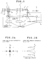
- FIG. 1 shows a block diagram of a first embodiment of an optical information-recording/reproducing apparatus including a volume holographic memory according to the present invention.
- a light beam emitted from a laser diode 1 is split by a translucent mirror 3 into a signal beam 4 and a reference beam 5.
- the two light beams are guided into an optical path of a signal beam optical system and an optical path of a reference beam optical system, respectively.
- a light beam emitted as a linearly polarized light is modulated by an ND (neutral density) filter such that it has a predetermined light intensity.
- ND neutral density
- a half-wave plate may be used to control a direction of deflection of the beam incident on the recording medium.
- the signal beam 4 reflected off the translucent mirror 3 passes through a shutter 6a, a reflecting mirror 6, a light beam expander 7, a spatial light modulator 8, and a Fourier transform lens 9 to be applied to a recording medium 10. More specifically, the signal beam 4 is expanded by the beam expander 7 into a parallel pencil of rays having a predetermined diameter, spatially modulated by the spatial light modulator 8 according to recording page data, i.e. spatially modulated to a two-dimensional grating patterns according to the permission or inhibition of transmission of each pixel, then subjected to Fourier transform by the Fourier transform lens 9 and converged on the recording medium 10, thereby forming an image in the recording medium as a Fourier transform image. Also in the present embodiment, the direction of deflection of the signal beam 4 may be controlled by the half-wave plate, and adjusted by an ND filter to have a predetermined light intensity.
- the reference beam 5 passes through a light beam expander 11 and a pager reflecting mirror 12 to be applied to the recording medium 10.
- the signal beam 4 and the reference beam 5 intersect with each other inside the recording medium 10.
- the reference beam 5 which passed through the translucent mirror 3 is expanded by the beam expander 11 into a parallel pencil of rays having a predetermined diameter.
- the reference beam 5 may have its light intensity adjusted by an ND filter.
- the reference beam 5 is controlled by the pager reflecting mirror 12 to be applied to the recording medium at respective predetermined angles. Paging operation of the pager reflecting mirror 12 is controlled by sliding of the mirror 12 and changing of its angle of deflection such that an identical portion of the recording medium is irradiated with reference beams 5 having respective different incidence angles.
- the shutter 6a In reproducing the recorded optical information, the shutter 6a is closed, and hence only the reference beam 5 reflected by the pager reflecting mirror 12 is irradiated on the recording medium 10, whereby diffracted light forms an image on a two-dimensional photodetector array 21 including a CCD via an inverse Fourier transform lens 20. Pixels of the CCD and pixels of an LCD are adjusted such that they have a one-to-one correspondence between them.
- the correspondence pattern between the CCD pixels and the LCD ones may be not only one-to-one but also one-to-four, four-to-one, or the like. Thus, when the information is reproduced, it is possible to read data by applying the reference beam 5 alone to the interference pattern recorded in the recording medium 10.
- a digital signal to be recorded is entered to a controller 30 and subjected to processing such as addition of an error-correcting code, binary coding, etc. Then, the digital signal is converted by a signal beam control driver 31 to a signal indicative of a page image array. Data of each page is then delivered as a page image to the transmission spatial light modulator 8 such as an LCD to form image data.
- the controller 30 controls a time period over which the recording medium 10 is to be irradiated with the two beams with the image data existing in the spatial light modulator 8 by means of a shutter control driver 32 that automatically controls the opening and closing the laser diode.
- the controller 30 shifts the pager reflecting mirror 12 by means of a reference beam control driver 33 to change an angle position of the mirror 12 in accordance with the image data, whereby the reference beam 5 set to enter the recording medium 10 at a predetermined incidence angle ( ⁇ ) is applied to the same over a predetermined time period to write a hologram therein.
- the procedure for sending a page image, setting the incidence angle of the reference beam 5, and recording a hologram is repeatedly carried out.
- One page of information is stored per incidence angle variably set to the reference beam 5.
- the process of information reproduction is as follows: the controller 30 causes the shutter 6a to close, and moves the pager reflecting mirror 12 by means of the reference beam control driver 33 to set the incidence angle of the reference beam 5 to a predetermined value which is identical to one of the values determined when the information was recorded; the reference beam alone is applied to the recording medium 10; and a diffracted light from one of the recorded interference patterns is focussed by the inverse Fourier transform lens 20 to form an image of the reproduced page on the two-dimensional photodetector array 21 including the CCD. It is necessary that the light intensity of the reference beam is set to a sufficiently low value, compared with the value used in recording, to prevent the recorded information from being erased.
- the controller 30 carries out signal processing, such as decoding, error correction processing, etc., of the photodetector output, whereby the information recorded in the recording medium 10 is read.
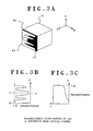
- a reference optical axis of the reference beam which is not set to an angle in an x direction, and a direction orthogonal to these z and x directions is set as a y direction
- a spatial frequency spectral distribution intensity occurs at spots symmetric with each other with respect to the optical axis of the signal beam on an x-y plane parallel to a Fourier surface.
- the light intensity is saturated particularly at the center of a 0-order light beam extending in the z direction as shown in FIG. 2B, which causes deformation of a reproduced image.
- the volume holographic memory-based optical information-recording/reproducing apparatus of the invention includes a second spatial beam modulating means 60 arranged in the optical path of the reference beam optical system for limiting the light intensity such that the cross section of the reference beam in the recording medium 10 has a light intensity distribution opposite in phase to that of the signal beam shown in FIG. 2B to reduce amplitude of electric field distribution within the recording medium resulting from the interference between the two light beams to a sufficiently low level to prevent saturation of the light intensity.
- the light intensity distribution of the signal beam in the recording medium 10 as shown in Fig.
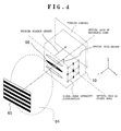
- the second spatial beam modulating means 60 modulates the reference beam such that the reference beam in the recording medium has a cross section having a light intensity distribution generally opposite in phase to the FIG. 2B light intensity distribution of the signal beam in the recording medium 10 resulting from transformation of the signal beam by the Fourier lens. More specifically, as shown in FIGS. 1 and 3A, the second spatial beam modulating means 60 comprises a liquid crystal panel 60 arranged in parallel with the y-z plane, which is electrically controlled to have its transmittance changed.
- the liquid crystal panel 60 is controlled such that it has an optically transparent portion 63 having a transmittance distribution opposite in phase to the FIG. 2B light intensity distribution of the signal beam, and an optically opaque portion 62. Further, the liquid crystal panel 60 can be controlled to have an optically transparent portion 63 having a transmittance distribution in which transmittance is lowest on a side of the recording medium 10 on which the signal beam impinges and progressively increases toward the opposite side as shown in FIG. 3C, and an optically opaque portion 62. Still further, as shown in FIG. 3A, the liquid crystal panel 60 may have a transmittance distribution formed by overlaying the transmittance distribution shown in FIG. 3B upon that shown in FIG. 3C. Any one of the above optically opaque portions 62 includes a semi-translucent portion formed according to the transmittance thereof.
- the LCD 60 is arranged in the optical path of the reference beam, particularly in the vicinity of the recording medium or in intimate contact with the same to spatially modulate the profile of the reference beam based on the spatial frequency spectral distribution of the signal beam, an absorption coefficient of the recording medium, and so forth, whereby the intensity of the reference beam is controlled not to be saturated at a spot of the Fourier surface at which the intensity of the signal beam is high.
- the intensity of the reference beam is relatively increased at a spot at which the intensity of the signal beam is low, so as to obtain diffraction efficiency.
- the effect can be enhanced by expanding the reference beam in cross section by the use of a light beam expander or the like.
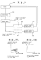
- the second spatial beam modulating means 60 may comprise a combination of a Fourier transform lens 64 and at least one diffraction grating 65 comprised of a liquid crystal shutter arranged in parallel with the y-z plane, other than the liquid crystal panel.
- the Fourier transform lens 64 is arranged on the optical axis of the reference beam such that its Fourier surface is spaced away from the optical axis of the signal beam.
- the diffraction grating 65 is arranged such that the reference beam transmitted through the Fourier transform lens 64 forms a light intensity distribution 66 of a 0-order diffracted light substantially in parallel with the optical axis of the signal beam.
- the Fourier transform lens system is inserted on the reference beam side, whereby the Fourier surfaces of the two beams at an intersection of these beams do not coincide with each other with resect to the origin, but the Fourier surface of the reference beam is offset along the optical axis of the reference beam toward a 1-order light-side of the signal beam.
- spatial light modulators for controlling irradiating position and quantity of light, respectively, inside and outside the Fourier transform lens system, respectively. These modulators make it possible to reduce the volume of the recording medium required for recording, enabling a larger number of pages of spatial multiple recording.
- a two-dimensional photodetector array 21 shown in FIG. 1, i.e. light-detecting means for detecting a reproduced diffracted light beam includes a CCD 70 arranged on a plane perpendicular to the optical axis of the diffracted light from the recording medium, a pinhole array 74 comprised of a flat shade 73 having a plurality of apertures 72 formed therethrough with a predetermined pitch in a manner corresponding to a matrix of light-receiving pixel elements 71 on the CCD 70 and held apart from the matrix of light-receiving pixel elements 71 in a manner movable along the CCD plane in directions orthogonal to each other, and drive elements 75 consisting of piezoelectric elements for driving the pinhole array 74 in the directions orthogonal to each other.
- an actual modularizing operation in a process of assembling and adjusting modules of a volume hologram-recording/reproducing apparatus using Fourier transform lenses requires extremely accurate positioning, for example, for mounting CCD photoreceptive elements at predetermined space intervals with an assembly tolerance of closer than space intervals of the CCD photoreceptive elements, so that the manufacturing step is a troublesome and time-consuming one.
- the two-dimensional photodetector array 21 of the present embodiment makes it possible to eliminate the above incovenience. That is, the movable pinhole array 74 driven by the piezoelectric elements is disposed slightly apart from the CCD pixels 71, which makes the assembly tolerance less close and permits fine adjustment after assemblage.
- FIG. 6A shows a case in which an optical adjustment actually carried meets criteria
- FIG. 6B shows cases in which the same is insufficient.
- outputs from adjacent pixel elements which should not receive light are also contained in the distribution of light intensity on the CCD.
- a contrast in an image formed by the CCD output signals is reduced.
- the pinhole array 74 is moved in the X-Y directions with reference to x and y positions by the drive elements 75, such as piezoelectric elements so as to prevent the beam from entering the adjacent pixels as stray light (S1, S2), whereby the CCD outputs are obtained (S3) and demodulated (S4), error is detected (S5), the amount of displacement in the X-Y directions is detected based on the results of the error detection (S6, S7), and adjustment is repeatedly carried out according to the detected amount of displacement in the X-Y direction for optimization of signal intensity obtained.
- the piezoelectric elements for driving the movable pinhole array is only required to move the pinhole array by ⁇ 0.5 pixel for the adjustments.
- an optimum open area of the LCD on the focus on the opposite side of the Fourier transform lens facing the CCD is in a range of 1 to 0.5.
- FIG. 8A shows a further embodiment according to the invention.
- the pinhole array 74 of the two-dimensional photodetector array 21 may comprise a microlens array having a plurality of convex lens 77 which are received in a plurality of apertures and a shielding material 78 filling space between the convex lenses 77.
- the pinhole array 74 may comprise a microlens array having distribution dioptric flat plate lenses 79 fitted in the corresponding apertures and the shielding material 78 filling space between the lenses 79.
- the volume holographic memory-based optical information-recording/reproducing apparatus is provided with monitoring means for detecting diffracted light leaking from a portion within the recording medium in which the reference beam and the signal beam intersect with each other.
- a signal from the monitoring means controls shutter control means for controlling blink of the signal beam.
- FIGS. 9A and 9B basically, recording of a hologram is carried out by recording optical mode coupling between a recording beam and the reference beam in the recording medium of photorefractive crystal as changes in refractive index occurring within the recording medium.
- the intensity of the light which the CCD receives is determined in two modes.
- light power is exchanged periodically between the reference beam and the signal beam, for example, in a recording medium using LiNbO 3 which is doped with Fe and positioned such that changes in the refractive index occur within the crystal according to an electro-optic constant r 13 , as shown in FIG. 9A, an image which is being recorded blinks repeatedly with formation of diffraction gratings.
- FIG. 9A shows a case in which there occurs an enhancement of contrast in light intensity of the diffracted light between light and dark caused by blinking
- FIG. 9B shows a case in which there simply occurs an increase in amount of the diffracted light.
- FIG. 10 shows an apparatus according to the present embodiment. Component parts and elements corresponding to those of the above embodiments shown in FIG. 1 are indicated by identical reference numerals, and description thereof is omitted.
- an adjustable filter 81 which is capable of attenuating light over a large adjustable range is provided for the two-dimensional photodetector array 21 of the CCD camera, and a mixture of the transmitted signal beam and the diffracted reference beam is detected with increased attenuation during recording. Diffraction efficiency is calculated back from the luminance of the reproduced image for real-time and optimum recording.
- luminance difference between the light and the dark blinking is monitored to keep track of the recording state and control the same.
- the luminance of an image which is being recorded increases with formation of diffraction gratings, so that the recording state is controlled such that the luminance reaches a predetermined level.
- An apparatus of this embodiment includes a laser 83, and a drive mechanism 85.
- the laser 83 serves as monitoring beam-irradiating means for applying a monitoring beam having a wavelength different from that of the signal beam to the portion within the recording medium 10 in which the reference beam and the signal beam intersect with each other.
- the driving mechanism 85 moves the monitoring beam-irradiating means such that a light receiver 84 as monitoring means can receive the monitoring light reflected off the portion within the recording medium 10.
- the monitoring means may comprise a two-dimensional photodetector array.
- the laser 83 uses a laser beam having a wavelength different from that of the signal beam as the monitoring beam.
- the laser 83 may consist of a He-Ne laser beam. Since the laser beam has the wavelength different from that of the signal beam, the Bragg angle is also different from that of the signal beam. This makes it possible to add a monitoring optical system to the conventional optical system for recording and reproduction of information.
- an angle multiple recording method is employed as the multiple recording method, it is required to change the incidence angle of the monitoring beam from the monitoring optical system as shown in FIG. 11. Therefore, the laser 83 and the light receiver 84 are shifted in position by the drive mechanism 85 as shown in the figure, to change the incidence angle of the monitoring beam incident on the recording medium.
- the drive mechanism 85 may include a movable stage and a galvano mirror, two pairs of galvano mirrors, or an audio optical deflecting (AOD) element.
- the monitoring optical system makes it possible to monitor formation of diffraction gratings during recording independently. Information obtained from the monitoring is fed back for use in controlling a recording time period.
- the light receiver 84 for monitoring comprises a CCD camera
- the light receiver 84 may comprise a photodiode. In this case, the adjustment for the pixel adjustment is not necessary, and hence its installation is simplified. The state of formation of diffraction ratings can be kept track of by monitoring the diffraction intensity.
- a conventional holographic memory made of lithium niobate (LN) information is recorded by utilizing the photorefractive effect. Since the photorefractive effect has no definite threshold value for recording, it is possible to record a relatively feeble light below 1 (W/cm 2 ). However, the photorefractive effect has no threshold value for record erasure, either, so that a record is degraded even by irradiation thereon for multiple recording or reproduction.
- a conventional technique to overcome this problem is to carry out scheduling in which the quantity of erasure of each page to be caused by recording operations of the other pages is calculated in advance, and initial recording is carried out to an increased degree corresponding to the calculated intensity.
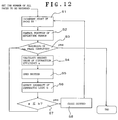
- FIG. 12 shows an example of a recording procedure carried out by the apparatus according to the present embodiment.
- the number of all recording pages is set, and the number of recorded pages is counted from an initial value thereof in step S1.
- position control of the reflecting mirror for the monitoring beam is performed in step S2, and it is determined in step S3 whether recording of all the pages is completed. If the recording is not completed, a desired value a of diffraction efficiency is calculated in step S4.
- the shutter is opened in step S5, and the intensity of diffracted light b is detected in step S6. In the following step S7, it is determined whether the intensity b is equal to or smaller than the desired value a.
- step S1 If the intensity b is equal to or larger than the desired value a, the program returns to step S1, wherein the number of the pages is counted again. On the other hand, if the intensity b is larger than the desired value a, the program returns to step S3, wherein it is judged that the recording of all the pages is completed, followed by terminating the program. Thus, it is possible to monitor recording on a page-by-page basis in real time.
Landscapes
- Physics & Mathematics (AREA)
- General Physics & Mathematics (AREA)
- Holo Graphy (AREA)
- Optical Recording Or Reproduction (AREA)
- Optical Head (AREA)
Applications Claiming Priority (2)
| Application Number | Priority Date | Filing Date | Title |
|---|---|---|---|
| JP08125898A JP3521113B2 (ja) | 1998-03-27 | 1998-03-27 | 体積ホログラフィックメモリ光情報記録再生装置 |
| JP8125898 | 1998-03-27 |
Publications (2)
| Publication Number | Publication Date |
|---|---|
| EP0945870A2 true EP0945870A2 (de) | 1999-09-29 |
| EP0945870A3 EP0945870A3 (de) | 2004-06-30 |
Family
ID=13741359
Family Applications (1)
| Application Number | Title | Priority Date | Filing Date |
|---|---|---|---|
| EP99302370A Withdrawn EP0945870A3 (de) | 1998-03-27 | 1999-03-26 | Optisches Informationsaufzeichnung-/wiedergabegerät basierend auf einem volumenholographischen Speicher |
Country Status (3)
| Country | Link |
|---|---|
| US (1) | US6088321A (de) |
| EP (1) | EP0945870A3 (de) |
| JP (1) | JP3521113B2 (de) |
Cited By (4)
| Publication number | Priority date | Publication date | Assignee | Title |
|---|---|---|---|---|
| WO2002021535A1 (en) * | 2000-08-25 | 2002-03-14 | Institut 'jozef Stefan' | Confocal holographic optical storage with non-overlapping records |
| WO2003091997A1 (en) * | 2002-04-26 | 2003-11-06 | Discovision Associates | Holographic data storage system |
| WO2004012016A1 (ja) * | 2002-07-31 | 2004-02-05 | Pioneer Corporation | 記録装置、再生装置及び記録再生装置 |
| EP1526414A4 (de) * | 2002-08-01 | 2008-04-23 | Pioneer Corp | Hologrammaufzeichnungs-/-wiedergabesystem |
Families Citing this family (40)
| Publication number | Priority date | Publication date | Assignee | Title |
|---|---|---|---|---|
| JP3608603B2 (ja) * | 1998-08-18 | 2005-01-12 | 富士ゼロックス株式会社 | 光記録方法および光記録装置 |
| US6958967B2 (en) * | 2000-11-17 | 2005-10-25 | Matsushita Electric Industrial Co., Ltd. | Holographic optical information recording/reproducing device |
| JP3639212B2 (ja) * | 2000-12-11 | 2005-04-20 | 株式会社オプトウエア | 光情報記録方法 |
| WO2003052752A1 (en) * | 2001-11-26 | 2003-06-26 | Access Optical Networks, Inc. | Method and apparatus for providing optical network interface using optical memory storage |
| WO2003094157A1 (en) * | 2002-05-02 | 2003-11-13 | Discovision Associates | Method and apparatus for recording to and reading from a multi-layer diffractive optics memory |
| US7149014B2 (en) * | 2003-04-18 | 2006-12-12 | California Institute Of Technology | Holographic memory using beam steering |
| CA2527879A1 (en) * | 2003-06-07 | 2004-12-23 | Aprilis, Inc. | High areal density holographic data storage system |
| JP3906831B2 (ja) * | 2003-09-22 | 2007-04-18 | 富士ゼロックス株式会社 | ホログラム記録方法 |
| US7127138B2 (en) * | 2003-11-20 | 2006-10-24 | The Boeing Company | Apparatus and method for directing a light beam to a target |
| JP4351551B2 (ja) * | 2004-02-17 | 2009-10-28 | Tdk株式会社 | ホログラフィック記録方法、ホログラフィック記録装置、ホログラフィック記録媒体、ホログラフィックメモリ再生方法及び装置 |
| JP4534517B2 (ja) * | 2004-02-18 | 2010-09-01 | ソニー株式会社 | ホログラム装置 |
| KR100589592B1 (ko) * | 2004-05-10 | 2006-06-19 | 주식회사 대우일렉트로닉스 | 홀로그래픽 디지털 데이터 시스템의 미러 각도 측정 및서보 장치 |
| JP2005352097A (ja) * | 2004-06-10 | 2005-12-22 | Nippon Hoso Kyokai <Nhk> | ホログラム記録方法、ホログラム再生方法、ホログラム記録装置、ホログラム再生装置、及びホログラム記録媒体 |
| JP4730081B2 (ja) * | 2005-12-19 | 2011-07-20 | 富士ゼロックス株式会社 | ホログラム記録方法及び装置 |
| DE602006015155D1 (de) * | 2006-01-13 | 2010-08-12 | Thomson Licensing | Intensitätsprofilkorrektur für Datenseiten für holografische Speicherung |
| US20070242141A1 (en) * | 2006-04-14 | 2007-10-18 | Sony Corporation And Sony Electronics Inc. | Adjustable neutral density filter system for dynamic range compression from scene to imaging sensor |
| US7733557B2 (en) * | 2006-04-24 | 2010-06-08 | Micron Technology, Inc. | Spatial light modulators with changeable phase masks for use in holographic data storage |
| WO2007132521A1 (ja) * | 2006-05-16 | 2007-11-22 | Fujitsu Limited | ホログラム記録装置およびホログラム記録方法 |
| WO2008001416A1 (en) * | 2006-06-26 | 2008-01-03 | Fujitsu Limited | Hologram recording device and hologram recording/reproducing method |
| WO2008001434A1 (en) * | 2006-06-28 | 2008-01-03 | Fujitsu Limited | Hologram recording device and hologram recording method |
| KR20080014533A (ko) * | 2006-08-11 | 2008-02-14 | 삼성전자주식회사 | 참조광 입사각 제어 장치 및 이를 구비하는 홀로그래픽정보 기록/재생 장치 |
| KR20080037179A (ko) * | 2006-10-25 | 2008-04-30 | 삼성전자주식회사 | 홀로그래픽 정보 기록/재생 장치 및 홀로그래픽 정보의기록/재생 방법 |
| KR20080052040A (ko) * | 2006-12-07 | 2008-06-11 | 삼성전자주식회사 | 홀로그래픽 정보 기록/재생 장치 및 상기 장치에서 북위치를 탐색하는 방법 |
| US7903526B2 (en) * | 2007-06-08 | 2011-03-08 | Lg Electronics Inc. | Recording/reproducing apparatus, method of reproducing data, and servo controlling method |
| KR101397434B1 (ko) * | 2007-06-21 | 2014-05-20 | 삼성전자주식회사 | 가변 크기의 조리개를 채용한 홀로그래픽 기록/재생 장치 |
| JP5211174B2 (ja) * | 2008-10-30 | 2013-06-12 | 株式会社日立製作所 | 情報処理装置及び記憶媒体 |
| US9625878B2 (en) * | 2009-03-10 | 2017-04-18 | Drexel University | Dynamic time multiplexing fabrication of holographic polymer dispersed liquid crystals for increased wavelength sensitivity |
| WO2010148280A2 (en) * | 2009-06-18 | 2010-12-23 | Cadet, Gardy | Method and system for re-writing with a holographic storage medium |
| US8045246B2 (en) * | 2009-06-18 | 2011-10-25 | Access Optical Networks, Inc. | Method and apparatus for bulk erasure in a holographic storage system |
| WO2010148282A2 (en) * | 2009-06-18 | 2010-12-23 | Paul Prucnal | An optical switch using a michelson interferometer |
| WO2010148283A2 (en) * | 2009-06-18 | 2010-12-23 | Paul Prucnal | Directly modulated spatial light modulator |
| US20100325513A1 (en) * | 2009-06-18 | 2010-12-23 | Peter Donegan | Integrated control electronics (ice) for a holographic storage system |
| WO2010148279A2 (en) * | 2009-06-18 | 2010-12-23 | Cadet, Gardy | Holographic storage system using angle-multiplexing |
| US8315489B2 (en) * | 2009-06-18 | 2012-11-20 | Paul Prucnal | Optical sensor array |
| US9752932B2 (en) | 2010-03-10 | 2017-09-05 | Drexel University | Tunable electro-optic filter stack |
| US8605562B2 (en) * | 2011-08-09 | 2013-12-10 | Samsung Electronics Co., Ltd. | Apparatus and method for recording micro-hologram |
| US9049413B2 (en) | 2013-07-30 | 2015-06-02 | Dolby Laboratories Licensing Corporation | Multiple stage modulation projector display systems having efficient light utilization |
| ES2768699T3 (es) * | 2013-07-30 | 2020-06-23 | Dolby Laboratories Licensing Corp | Sistemas de pantalla de proyector que tienen dirección del haz de espejo no-mecánica |
| KR101840132B1 (ko) * | 2016-10-19 | 2018-03-19 | 한국과학기술원 | 다중 산란을 이용한 다기능 광학 장치 및 방법 |
| CN112304246B (zh) * | 2020-12-21 | 2021-03-23 | 苏州大学 | 基于空间相干结构调控的光学成像系统及成像方法 |
Family Cites Families (16)
| Publication number | Priority date | Publication date | Assignee | Title |
|---|---|---|---|---|
| US3604778A (en) * | 1969-10-22 | 1971-09-14 | Bell Telephone Labor Inc | Fourier transform recording with random phase shifting |
| US3652144A (en) * | 1970-09-09 | 1972-03-28 | Radiation Inc | Amplitude weighting in holography |
| FR2284889A1 (fr) * | 1974-09-14 | 1976-04-09 | Nippon Telegraph & Telephone | Dephaseur pour enregistrement par hologramme |
| US4889780A (en) * | 1988-03-14 | 1989-12-26 | Hughes Aircraft Company | Multiple exposure hologram for minimizing crosstalk |
| US5291471A (en) * | 1989-09-22 | 1994-03-01 | Russell James T | Recording/reproducing system using phase encoding of optical storage medium |
| US5543251A (en) * | 1990-06-29 | 1996-08-06 | E. I. Du Pont De Nemours And Company | Method of recording plural holographic images into a holographic recording material by temporal interleaving |
| US5339305A (en) * | 1992-08-14 | 1994-08-16 | Northrop Grumman Corporation | Disk-based optical correlator and method |
| US5510912A (en) * | 1993-08-09 | 1996-04-23 | International Business Machines Corporation | Method and apparatus for modulation of multi-dimensional data in holographic storage |
| US5438439A (en) * | 1993-08-13 | 1995-08-01 | Mok; Fai | Non-destructive readout mechanism for volume holograms using two wavelengths |
| US5696613A (en) * | 1993-08-20 | 1997-12-09 | Tamarack Storage Devices | Method and apparatus for multiplexing data in different planes of incidence of a thin holographic storage media |
| WO1996010728A1 (fr) * | 1994-09-30 | 1996-04-11 | Komatsu Ltd. | Dispositif optique confocal |
| US5777760A (en) * | 1996-05-10 | 1998-07-07 | Quantum Corporation | Position feedback system for volume holographic storage media |
| US5822090A (en) * | 1996-05-29 | 1998-10-13 | Quinta Corporation | Utilization of ferroelectric domain screening for high capacity holographic memory |
| US5838650A (en) * | 1996-06-26 | 1998-11-17 | Lucent Technologies Inc. | Image quality compensation method and apparatus for holographic data storage system |
| US5859808A (en) * | 1997-06-24 | 1999-01-12 | Lucent Technologies Inc. | System and method for steering fresnel region data to access data locations in a holographic memory |
| US5914802A (en) * | 1997-07-18 | 1999-06-22 | Northrop Grumman Corporation | Combined spatial light modulator and phase mask for holographic storage system |
-
1998
- 1998-03-27 JP JP08125898A patent/JP3521113B2/ja not_active Expired - Fee Related
-
1999
- 1999-03-23 US US09/274,969 patent/US6088321A/en not_active Expired - Lifetime
- 1999-03-26 EP EP99302370A patent/EP0945870A3/de not_active Withdrawn
Cited By (5)
| Publication number | Priority date | Publication date | Assignee | Title |
|---|---|---|---|---|
| WO2002021535A1 (en) * | 2000-08-25 | 2002-03-14 | Institut 'jozef Stefan' | Confocal holographic optical storage with non-overlapping records |
| WO2003091997A1 (en) * | 2002-04-26 | 2003-11-06 | Discovision Associates | Holographic data storage system |
| WO2004012016A1 (ja) * | 2002-07-31 | 2004-02-05 | Pioneer Corporation | 記録装置、再生装置及び記録再生装置 |
| US7236441B2 (en) | 2002-07-31 | 2007-06-26 | Pioneer Corporation | Recording device, reproduction device, and recording/reproduction device |
| EP1526414A4 (de) * | 2002-08-01 | 2008-04-23 | Pioneer Corp | Hologrammaufzeichnungs-/-wiedergabesystem |
Also Published As
| Publication number | Publication date |
|---|---|
| US6088321A (en) | 2000-07-11 |
| EP0945870A3 (de) | 2004-06-30 |
| JPH11282331A (ja) | 1999-10-15 |
| JP3521113B2 (ja) | 2004-04-19 |
Similar Documents
| Publication | Publication Date | Title |
|---|---|---|
| US6088321A (en) | Volume holographic memory apparatus having a reference beam and a signal beam with opposite intensity distributions | |
| US6256281B1 (en) | Volume holographic memory-based optical information-recording/reproducing apparatus | |
| EP0021754B1 (de) | Elektrooptischer Modulator und seine Verwendung | |
| US7002891B2 (en) | Apparatus and method for recording and reproducing information to and from an optical storage medium | |
| US7372602B2 (en) | Method for recording and reproducing holographic data and an apparatus therefor | |
| US4012108A (en) | Hologram memory apparatus | |
| KR100611420B1 (ko) | 공간광변조기 및 홀로그램 기록재생장치 | |
| KR20030004331A (ko) | 데이터 마크를 매체 상에 분포시키는 방법, 데이터를홀로그램으로 기록 및 판독하는 방법 및 장치 | |
| US6320683B1 (en) | Optical information recording and reproducing apparatus using a volume holographic memory | |
| EP1528442A1 (de) | Räumlicher optischer modulator | |
| EP1246031A2 (de) | Aufzeichnungsmaterial für Hologramme, Verfahren zum Aufzeichnen und Wiedergeben von Hologrammen und Vorrichtung zum Aufzeichnen und Wiedergeben von Hologrammen | |
| EP1507177A1 (de) | Hologrammaufzeichnungseinrichtung des multiplexaufzeichnungstyps, verfahren, hologrammwiedergabeeinrichtung und verfahren | |
| EP1542097A1 (de) | Hologrammaufzeichnungs-/-wiedergabeverfahren und hologrammaufzeichnungs-/-wiedergabeeinrichtung | |
| CA1173144A (en) | Switching device for optical beams and telephone exchange incorporating such a device | |
| US7313072B2 (en) | Method for recording and reproducing holographic data and holographic recording medium | |
| US6862120B2 (en) | Hologram recording medium, hologram recording method and hologram recording and reproducing apparatus | |
| US6301028B1 (en) | Holographic memory and optical information recording and reproducing apparatus using the same | |
| US6049401A (en) | Volume holographic memory | |
| US6504810B2 (en) | Optical information recording/reproducing system | |
| US20020085250A1 (en) | Phase-conjugate holographic data storage device using a multifocal lens and data storage method thereof | |
| US6414762B1 (en) | Optical information recording and reproducing apparatus using a holographic memory | |
| US7808877B2 (en) | Optical recording device and optical recording method | |
| US20060164705A1 (en) | Hologram system | |
| GB2332754A (en) | Volume holographic data storage system | |
| KR100397479B1 (ko) | 각도 멀티플렉싱을 이용한 홀로그램 저장장치 |
Legal Events
| Date | Code | Title | Description |
|---|---|---|---|
| PUAI | Public reference made under article 153(3) epc to a published international application that has entered the european phase |
Free format text: ORIGINAL CODE: 0009012 |
|
| AK | Designated contracting states |
Kind code of ref document: A2 Designated state(s): AT BE CH CY DE DK ES FI FR GB GR IE IT LI LU MC NL PT SE |
|
| AX | Request for extension of the european patent |
Free format text: AL;LT;LV;MK;RO;SI |
|
| PUAL | Search report despatched |
Free format text: ORIGINAL CODE: 0009013 |
|
| AK | Designated contracting states |
Kind code of ref document: A3 Designated state(s): AT BE CH CY DE DK ES FI FR GB GR IE IT LI LU MC NL PT SE |
|
| AX | Request for extension of the european patent |
Extension state: AL LT LV MK RO SI |
|
| RIC1 | Information provided on ipc code assigned before grant |
Ipc: 7G 03H 1/04 B Ipc: 7G 11B 7/00 B Ipc: 7G 03H 1/16 B Ipc: 7G 11C 13/04 A |
|
| 17P | Request for examination filed |
Effective date: 20040723 |
|
| 17Q | First examination report despatched |
Effective date: 20041006 |
|
| AKX | Designation fees paid |
Designated state(s): DE FR GB |
|
| STAA | Information on the status of an ep patent application or granted ep patent |
Free format text: STATUS: THE APPLICATION IS DEEMED TO BE WITHDRAWN |
|
| 18D | Application deemed to be withdrawn |
Effective date: 20050217 |