EP0944866B1 - Verfahren zur schaufeltemperaturschätzung in einer dampfturbine - Google Patents
Verfahren zur schaufeltemperaturschätzung in einer dampfturbine Download PDFInfo
- Publication number
- EP0944866B1 EP0944866B1 EP97951539A EP97951539A EP0944866B1 EP 0944866 B1 EP0944866 B1 EP 0944866B1 EP 97951539 A EP97951539 A EP 97951539A EP 97951539 A EP97951539 A EP 97951539A EP 0944866 B1 EP0944866 B1 EP 0944866B1
- Authority
- EP
- European Patent Office
- Prior art keywords
- values
- blade temperature
- data
- blade
- ann
- Prior art date
- Legal status (The legal status is an assumption and is not a legal conclusion. Google has not performed a legal analysis and makes no representation as to the accuracy of the status listed.)
- Expired - Lifetime
Links
- 238000000034 method Methods 0.000 title claims abstract description 50
- 238000013528 artificial neural network Methods 0.000 claims abstract description 32
- 238000005259 measurement Methods 0.000 claims abstract description 22
- 238000012549 training Methods 0.000 claims abstract description 14
- 238000002474 experimental method Methods 0.000 claims abstract description 7
- XLYOFNOQVPJJNP-UHFFFAOYSA-N water Substances O XLYOFNOQVPJJNP-UHFFFAOYSA-N 0.000 claims abstract description 5
- 238000004364 calculation method Methods 0.000 claims abstract description 4
- 238000013459 approach Methods 0.000 abstract description 6
- 230000008569 process Effects 0.000 description 34
- 238000010586 diagram Methods 0.000 description 18
- 238000012544 monitoring process Methods 0.000 description 10
- 238000004891 communication Methods 0.000 description 7
- 238000012546 transfer Methods 0.000 description 7
- 230000009471 action Effects 0.000 description 6
- 238000012360 testing method Methods 0.000 description 5
- 230000006399 behavior Effects 0.000 description 4
- 238000004458 analytical method Methods 0.000 description 3
- 239000003795 chemical substances by application Substances 0.000 description 3
- 238000007906 compression Methods 0.000 description 3
- 230000006870 function Effects 0.000 description 3
- 238000010438 heat treatment Methods 0.000 description 3
- 230000002452 interceptive effect Effects 0.000 description 3
- 238000013178 mathematical model Methods 0.000 description 3
- 238000012986 modification Methods 0.000 description 3
- 230000004048 modification Effects 0.000 description 3
- 238000005457 optimization Methods 0.000 description 3
- 238000010200 validation analysis Methods 0.000 description 3
- 238000004422 calculation algorithm Methods 0.000 description 2
- 230000006835 compression Effects 0.000 description 2
- 238000001816 cooling Methods 0.000 description 2
- 230000006378 damage Effects 0.000 description 2
- 238000013500 data storage Methods 0.000 description 2
- 238000011161 development Methods 0.000 description 2
- 230000000694 effects Effects 0.000 description 2
- RLQJEEJISHYWON-UHFFFAOYSA-N flonicamid Chemical compound FC(F)(F)C1=CC=NC=C1C(=O)NCC#N RLQJEEJISHYWON-UHFFFAOYSA-N 0.000 description 2
- 239000012530 fluid Substances 0.000 description 2
- 238000007726 management method Methods 0.000 description 2
- 239000000463 material Substances 0.000 description 2
- 238000004886 process control Methods 0.000 description 2
- 238000012545 processing Methods 0.000 description 2
- 238000012800 visualization Methods 0.000 description 2
- 241001125929 Trisopterus luscus Species 0.000 description 1
- 208000027418 Wounds and injury Diseases 0.000 description 1
- 230000003213 activating effect Effects 0.000 description 1
- 230000004913 activation Effects 0.000 description 1
- 230000004075 alteration Effects 0.000 description 1
- 230000009286 beneficial effect Effects 0.000 description 1
- 230000008901 benefit Effects 0.000 description 1
- 238000006243 chemical reaction Methods 0.000 description 1
- 230000019771 cognition Effects 0.000 description 1
- 239000012141 concentrate Substances 0.000 description 1
- 238000010276 construction Methods 0.000 description 1
- 238000000354 decomposition reaction Methods 0.000 description 1
- 238000010237 hybrid technique Methods 0.000 description 1
- 230000006872 improvement Effects 0.000 description 1
- 230000000977 initiatory effect Effects 0.000 description 1
- 208000014674 injury Diseases 0.000 description 1
- 230000001537 neural effect Effects 0.000 description 1
- 238000013021 overheating Methods 0.000 description 1
- 230000000644 propagated effect Effects 0.000 description 1
- 230000001902 propagating effect Effects 0.000 description 1
- 238000003303 reheating Methods 0.000 description 1
- 239000000523 sample Substances 0.000 description 1
- 238000005070 sampling Methods 0.000 description 1
- 238000000926 separation method Methods 0.000 description 1
- 238000004088 simulation Methods 0.000 description 1
- 238000010561 standard procedure Methods 0.000 description 1
- 238000004326 stimulated echo acquisition mode for imaging Methods 0.000 description 1
- 238000012795 verification Methods 0.000 description 1
Images


Classifications
-
- G—PHYSICS
- G05—CONTROLLING; REGULATING
- G05B—CONTROL OR REGULATING SYSTEMS IN GENERAL; FUNCTIONAL ELEMENTS OF SUCH SYSTEMS; MONITORING OR TESTING ARRANGEMENTS FOR SUCH SYSTEMS OR ELEMENTS
- G05B13/00—Adaptive control systems, i.e. systems automatically adjusting themselves to have a performance which is optimum according to some preassigned criterion
- G05B13/02—Adaptive control systems, i.e. systems automatically adjusting themselves to have a performance which is optimum according to some preassigned criterion electric
-
- G—PHYSICS
- G05—CONTROLLING; REGULATING
- G05B—CONTROL OR REGULATING SYSTEMS IN GENERAL; FUNCTIONAL ELEMENTS OF SUCH SYSTEMS; MONITORING OR TESTING ARRANGEMENTS FOR SUCH SYSTEMS OR ELEMENTS
- G05B17/00—Systems involving the use of models or simulators of said systems
- G05B17/02—Systems involving the use of models or simulators of said systems electric
-
- F—MECHANICAL ENGINEERING; LIGHTING; HEATING; WEAPONS; BLASTING
- F01—MACHINES OR ENGINES IN GENERAL; ENGINE PLANTS IN GENERAL; STEAM ENGINES
- F01K—STEAM ENGINE PLANTS; STEAM ACCUMULATORS; ENGINE PLANTS NOT OTHERWISE PROVIDED FOR; ENGINES USING SPECIAL WORKING FLUIDS OR CYCLES
- F01K13/00—General layout or general methods of operation of complete plants
- F01K13/02—Controlling, e.g. stopping or starting
-
- Y—GENERAL TAGGING OF NEW TECHNOLOGICAL DEVELOPMENTS; GENERAL TAGGING OF CROSS-SECTIONAL TECHNOLOGIES SPANNING OVER SEVERAL SECTIONS OF THE IPC; TECHNICAL SUBJECTS COVERED BY FORMER USPC CROSS-REFERENCE ART COLLECTIONS [XRACs] AND DIGESTS
- Y10—TECHNICAL SUBJECTS COVERED BY FORMER USPC
- Y10S—TECHNICAL SUBJECTS COVERED BY FORMER USPC CROSS-REFERENCE ART COLLECTIONS [XRACs] AND DIGESTS
- Y10S706/00—Data processing: artificial intelligence
- Y10S706/902—Application using ai with detail of the ai system
- Y10S706/903—Control
- Y10S706/904—Manufacturing or machine, e.g. agricultural machinery, machine tool
Definitions
- temperature measuring devices are installed at the respective stages of the HP and LP casings. These measurements provides an indication to the operator or supervising engineer in charge whenever the blade temperature exceeds its limit.
- the need for blade temperature monitoring for smaller and older turbine, as well as a more practical and cost effective ways than installing temperature probes, has led to a need, herein recognized, for a practical system for estimating in real time and monitoring turbine blade temperature during operation.
- the present invention relates to a method for blade temperature estimation in a steam turbine as defined in claim 1.
- the present invention is intended to be practiced preferrably with the application of a programmable computer.
- a method for blade temperature estimation in a steam turbine utilizes measurement values including pressure and temperature at locations other than directly at the blades, principally at the input and output stages.
- blade temperature is simulated by using a water/steam cycle analysis program as well as by directed experiments.
- An artificial neural network (ANN) is trained by presenting the measurement values and the blade temp values. In a present exemplary embodiment, it is found that 4 values provide a satisfactory result. In one method the ANN is used directly to derive operating blade temp values.
- a hybrid approach 5 measured values are utilized.
- a subset of, for example, 4 parameter values is used for training the ANN and another subset of, for example, 3 values is used for performing a calculation for another intermediate parameter.
- a blade temperature is calculated.
- the user interface provides a real-time information display for a supervising engineer in charge of turbine operation so that critical parameter values and undesirable combinations of operating conditions are readily observed and deviations are made apparent so that corrective action can be initiated rapidly. While graph plots of parameters can be readily presented, such a format generally does not readily provide an overall picture of the state of the turbine with regard to the distribution and combination of temperature, pressure, steam wetness or superheat, and turbulence effects.
- an overview of the operating situation is made more readily apparent by representing the operating expansion and compression processes by lines on a Mollier enthalpy/entropy chart.
- real-time parameter values and parameter trends are also presented.
- the supervising engineer can more quickly identify and correct undesirable and potentially troublesome operation conditions.
- a system utilizes a hybrid ANN (artificial neural network)-algorithmic based scheme for estimating the blade temperature from other measurements which are commonly available.
- the commonly available measurement values are herein utilized.
- the training data for the ANN includes both data generated by mathematical model and by experiment.
- the windage modules for HP and LP turbines in accordance with the present invention will provide the operator with an estimation of the blade temperature at the respective turbine stages.
- the interactive user interface herein disclosed displays the real-time value, a trend graph of these values, and the respective states within the Mollier diagram. Supervisory recommendation may be deduced from the estimation and other available measurement values.
- On-line visualization of the expansion/compression lines is especially beneficial for other parts of the turbine which are subject to overheating, due, in the present particular case, to the windage phenomenon.
- the LP turbine For heating steam turbines when the control valves, for example, in the cross over line for the two lower heaters are closed, the LP turbine requires cooling steam to hold within permissible limits the temperature rise caused by windage in the last stage. In this operating mode, the steam in the LP turbine absorbs energy resulting from the windage losses which predominate significantly within the last stages.
- DIGEST is a modular monitoring system for power system plant developed by the KWU-FTP activity of Siemens Aktiengesellschaft, (Simens AG), a corporation of Germany. DIGEST features a modular system architecture which can be divided into six different levels which will be explain briefly below. The module components are written in C, with much flexibility in building any structure of choice.
- the proposed windage module system architecture is shown in Figure 1.
- the first two levels are already available as part of DIGEST. Modifications were done to the administrative and data levels. Modifications in both the communication and data levels include parameter specification which is needed for requesting the module-specific data through the data bus,and for creating the data server and data base.
- the main windage module development is done mainly at the action and presentation levels.
- the six levels in the windage module are:
- the information is presented in several layers starting with the main windage screen which will mainly show the blade temperatures.
- the subsequent layers will show the detail conditions for each turbine section. These layers will provide information on all parameter values which are relevant to the operator for making appropriate decisions concerning the turbine operation. Further detail on the process within this level is provided in the following sections. detail in the next section.
- a development screen is optionally provided for accessing some internal module and system parameters or processes; however, principally because of security reasons, this feature may preferrably be omitted in an actual working version.
- the monitoring process may not always be necessary to cycle at the same rate at all times; it should depend on the turbine operating conditions. Several scenarios can be pre-determined for each specific turbine. For example, no load, full load, and low load during slow shutdown, start-up, and load rejection.
- the monitoring cycle should be adjusted automatically for different conditions, depending on their criticalities, and the respective display may be arranged to pop-up to assist the operator.
- the windage module basically has two main processes, the background process and the interactive display process.
- the background process is responsible for obtaining the necessary parameter values, calculating the blade temperature at a predefine rate, and recording the relevant information into the appropriate shared memory and data base.
- the interactive display process will show the necessary or requested information graphically at any point of time. The process rate is limited by the minimum amount of time required before all measurements stabilize, and will vary based on the severity of the turbine condition. Operation near the critical blade temperature may require faster process rate.
- the training sub-structure is responsible for producing the appropriate weights and parameters that will be used in the monitoring module. This process is done off-line and is not controllable through the GUI interface.
- the network is trained using the simulated data obtained by computing the estimated temperature using the analytical means for the expected normal operating domain, and actual data obtain from field experiments. The experiments concentrate on generating data in specific low steam flow conditions, such as shutdowns, loss of loads, and start-ups. This arrangement is expected to be able to estimate the blade temperature for the entire turbine operating ranges.
- Minimal inputs to the estimator are the real-time measurement values of the pressure of the main steam, temperature of the main steam, pressure of the third stage and exhaust pressure. Additional inputs can be optionally provided and evaluated.
- the background process will obtain measurement data, calculate the blade temperature and other necessary values, and store those values in appropriate locations.
- the process sequences are as follows:
- the estimator will calculate the blade temperature value using the measurement values.
- the input measurment values used for estimating the blade temperature, at least for the HP turbine, are:
- the blade temperature estimation and other measurement parameters are then stored in two different places: the Data Base and intermediate Shared Memory.
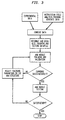
- Figure 3 shows the general traning process which applicable to the ANN-module either in the direct approach or the hybrid approach. The only difference is in the input-parameters as indicated in the background process. The process can be described as follows:
- the first step is data construction which basically combines the data obtained from simulation using water/steam cycle analysis and data obtained from the experiments.
- Such analysis is for example included in thermodynamics modules within the DIGEST system.
- the water/steam cycle analysis is used inside the themodynamic module in the DIGEST system.
- the DIGEST monitoring system is currently available in the market through SIEMENS AG.
- the data is re- formatted such it matches the input format of the ANN.
- the data is then reorganized by separating the data into two separate data files where one is used for training and validation purposes, and one for testing purposes. Although there is no certain rule for regrouping the available data, data should be reorganized such that all operating regions should be well represented. In accordance with the present exemplary embodiment, 80% of the available data is utilized for training and validation and the rest for testing.
- the ANN structure is a standard multilayer, with 1 hidden layer.
- the number of hidden units may vary from 4 to 10 without significant improvement in performance: a longer traning period is needed for larger number of hidden units, and it may run the risk of overfitting.
- the ANN parameters connection weights and unit's threshold values
- the training parameters must be modified until a solution is obtained.
- the graphical user interface will also able to show the turbine conditions within the steam behavior Mollier diagram.
- This diagram also called a Mollier chart, entropy/enthalpy diagram, or a total heat/entropy diagram, serves as a scientist and a plant. Therefore, this on-line turbine condition visualization will better help a user in taking appropriate control actions.
- GUI process must be initiated by the user. It will access values stored by the background process as required.
- the GUI process follows the following steps (see the correponding illustration in Figure 4).
- the Windage Graphical User Interface Module can be initiated independently or from within DIGEST. This will automatically initiate the connection to the Shared Memory unit.
- the shared memory unit is basically a routine which manages the access and transfer of data between the GUI and any process outside it which mainly includes a buffer.
- the 'turbine overview window' gives the current value of the blade temperature, as well as other information which may be important for the user to make any decision concerning the control of the turbine.
- the Mollier diagram is generated based on the standard thermodynamic calculation available on any thermodynamic text book such as the afore-mentioned books.
- a routine is herein used which will generate the background Mollier grid, and then overlay the expansion data which are calculated from the current measurement values on top of the grid.
- such a routine is available from Siemens AG in VISUM, a user manual, Version 3, October 1992.
- the trend diagram allows the selection of up to ten parameters to be shown at the same time.
- the maximum number of parameters that can be shown is essentially unlimited; however, any number larger than ten will cause difficulties in viewing the graph itself. It has the same feature as feature #2 in the Mollier diagram.
- the exact value within a graph can be found by clicking on the desired point. The exact value will be displayed under the corresponding axis.
- the user can further analyze the data by selecting the 'FREE GRAPHICS' which will give the user access to the complete data base. This component is provided within the DIGEST system.
- the GUI display process will access the necessary data from the Shared Memory, with the exception of the FREE GRAPHICS routines which will access data from the data base through the data server.
Landscapes
- Engineering & Computer Science (AREA)
- Physics & Mathematics (AREA)
- General Physics & Mathematics (AREA)
- Automation & Control Theory (AREA)
- Chemical & Material Sciences (AREA)
- Combustion & Propulsion (AREA)
- Mechanical Engineering (AREA)
- General Engineering & Computer Science (AREA)
- Health & Medical Sciences (AREA)
- Artificial Intelligence (AREA)
- Computer Vision & Pattern Recognition (AREA)
- Evolutionary Computation (AREA)
- Medical Informatics (AREA)
- Software Systems (AREA)
- Control Of Turbines (AREA)
- Testing And Monitoring For Control Systems (AREA)
- Turbine Rotor Nozzle Sealing (AREA)
Claims (5)
- Verfahren zum Schätzen der Schaufeltemperatur in einer Dampfturbine, wobei Messungsparameterwerte verwendet werden, die den Druck und die Temperatur enthalten, und zwar an Orten, die mindestens entweder die Eingangsstufe oder die Ausgangsstufe enthalten, und das Verfahren die Schritte umfasst:das Simulieren der Schaufeltemperaturwerte mit Hilfe eines Wasser/Dampf-Zyklusanalyseprogramms und durch gezielte Versuche;das Trainieren eines künstlichen neuronalen Netzwerks (ANN), indem man die Messwerte und die Schaufeltemperaturwerte in das Netzwerk einspeist; unddas Anlegen von Echtzeit-Messwerten an das künstliche neuronale Netzwerk (ANN).
- Verfahren zum Schätzen der Schaufeltemperatur nach Anspruch 1, wobei vier Messwerte verwendet werden.
- Verfahren zum Schätzen der Schaufeltemperatur nach Anspruch 1, wobei das künstliche neuronale Netzwerk (ANN) direkt dazu verwendet wird, die Betriebstemperaturwerte der Schaufeln zu bestimmen.
- Verfahren zum Schätzen der Schaufeltemperatur nach Anspruch 3, umfassend die Schritte:Erzeugen einer ersten Untermenge der Parameter werte;Verwenden der ersten Untermenge zum Trainieren des künstlichen neuronalen Netzwerks (ANN) ;Erzeugen einer zweiten Untermenge der Parameter werte;Verwenden der zweiten Untermenge zum Ausführen einer Berechnung, die einen Zwischenparameter liefert; undVerwenden des Zwischenparameters und eines der gemessenen Parameterwerte zum Berechnen eines Schaufeltemperaturwerts.
- Verfahren zum Schätzen der Schaufeltemperatur nach Anspruch 4, wobei fünf gemessene Parameterwerte verwendet werden und die erste Untermenge vier gemessene Parameter umfasst.
Applications Claiming Priority (3)
| Application Number | Priority Date | Filing Date | Title |
|---|---|---|---|
| US764381 | 1996-12-13 | ||
| US08/764,381 US5832421A (en) | 1996-12-13 | 1996-12-13 | Method for blade temperature estimation in a steam turbine |
| PCT/US1997/022159 WO1998026336A1 (en) | 1996-12-13 | 1997-12-05 | A method for blade temperature estimation in a steam turbine |
Publications (2)
| Publication Number | Publication Date |
|---|---|
| EP0944866A1 EP0944866A1 (de) | 1999-09-29 |
| EP0944866B1 true EP0944866B1 (de) | 2001-09-05 |
Family
ID=25070566
Family Applications (1)
| Application Number | Title | Priority Date | Filing Date |
|---|---|---|---|
| EP97951539A Expired - Lifetime EP0944866B1 (de) | 1996-12-13 | 1997-12-05 | Verfahren zur schaufeltemperaturschätzung in einer dampfturbine |
Country Status (12)
| Country | Link |
|---|---|
| US (1) | US5832421A (de) |
| EP (1) | EP0944866B1 (de) |
| JP (1) | JP4005143B2 (de) |
| KR (1) | KR100523382B1 (de) |
| CN (1) | CN1105950C (de) |
| AT (1) | ATE205310T1 (de) |
| CZ (1) | CZ300956B6 (de) |
| DE (1) | DE69706563T2 (de) |
| ES (1) | ES2167023T3 (de) |
| PL (1) | PL185983B1 (de) |
| RU (1) | RU2213997C2 (de) |
| WO (1) | WO1998026336A1 (de) |
Families Citing this family (22)
| Publication number | Priority date | Publication date | Assignee | Title |
|---|---|---|---|---|
| US7690840B2 (en) | 1999-12-22 | 2010-04-06 | Siemens Energy, Inc. | Method and apparatus for measuring on-line failure of turbine thermal barrier coatings |
| US7035834B2 (en) * | 2002-05-15 | 2006-04-25 | Caterpillar Inc. | Engine control system using a cascaded neural network |
| US20040082069A1 (en) * | 2002-10-25 | 2004-04-29 | Liang Jiang | Systems and methods for estimating exposure temperatures and remaining operational life of high temperature components |
| CN1298458C (zh) * | 2003-09-29 | 2007-02-07 | 宝山钢铁股份有限公司 | 一种rh精炼炉钢液温度实时预测方法 |
| CN100338447C (zh) * | 2004-07-24 | 2007-09-19 | 桂林电子工业学院 | 高温高压密闭腔内的温度测量方法 |
| US7021126B1 (en) * | 2004-09-15 | 2006-04-04 | General Electric Company | Methods for low-cost estimation of steam turbine performance |
| FR2876152B1 (fr) * | 2004-10-06 | 2006-12-15 | Renault Sas | Procede et systeme ameliores d'estimation d'une temperature des gaz d'echappement et moteur a combustion interne equipe d'un tel systeme |
| US7654734B2 (en) | 2005-05-10 | 2010-02-02 | General Electric Company | Methods and devices for evaluating the thermal exposure of a metal article |
| US8065022B2 (en) * | 2005-09-06 | 2011-11-22 | General Electric Company | Methods and systems for neural network modeling of turbine components |
| US7432505B2 (en) * | 2006-05-04 | 2008-10-07 | Siemens Power Generation, Inc. | Infrared-based method and apparatus for online detection of cracks in steam turbine components |
| US20100298996A1 (en) * | 2007-10-16 | 2010-11-25 | Gadinger Joerg | Method for operating a power station |
| US8478473B2 (en) * | 2008-07-28 | 2013-07-02 | General Electric Company | Method and systems for controlling gas turbine engine temperature |
| JP5804668B2 (ja) * | 2009-06-10 | 2015-11-04 | 三菱重工業株式会社 | 面内圧縮強度評価装置及び方法 |
| US8813498B2 (en) | 2010-06-18 | 2014-08-26 | General Electric Company | Turbine inlet condition controlled organic rankine cycle |
| CN102541025B (zh) * | 2012-01-29 | 2014-04-09 | 上海锅炉厂有限公司 | 一种基于水和水蒸汽热力性质iapws-if97的实时控制方法 |
| US8903753B2 (en) * | 2012-02-06 | 2014-12-02 | General Electric Company | Steam turbine performance testing |
| JP6092723B2 (ja) | 2013-06-25 | 2017-03-08 | 三菱日立パワーシステムズ株式会社 | 蒸気タービンプラントの起動制御装置 |
| US10954824B2 (en) | 2016-12-19 | 2021-03-23 | General Electric Company | Systems and methods for controlling drum levels using flow |
| US10677102B2 (en) | 2017-02-07 | 2020-06-09 | General Electric Company | Systems and methods for controlling machinery stress via temperature trajectory |
| RU2686385C1 (ru) * | 2018-05-23 | 2019-04-25 | федеральное государственное автономное образовательное учреждение высшего образования "Санкт-Петербургский национальный исследовательский университет информационных технологий, механики и оптики" (Университет ИТМО) | Способ спектрометрического определения температуры потока газов |
| GB201908494D0 (en) | 2019-06-13 | 2019-07-31 | Rolls Royce Plc | Computer-implemented methods for training a machine learning algorithm |
| GB201908496D0 (en) | 2019-06-13 | 2019-07-31 | Rolls Royce Plc | Computer-implemented methods for determining compressor operability |
Family Cites Families (23)
| Publication number | Priority date | Publication date | Assignee | Title |
|---|---|---|---|---|
| US4025765A (en) * | 1972-04-26 | 1977-05-24 | Westinghouse Electric Corporation | System and method for operating a steam turbine with improved control information display |
| US3873817A (en) * | 1972-05-03 | 1975-03-25 | Westinghouse Electric Corp | On-line monitoring of steam turbine performance |
| US4227093A (en) * | 1973-08-24 | 1980-10-07 | Westinghouse Electric Corp. | Systems and method for organizing computer programs for operating a steam turbine with digital computer control |
| JPS6024283B2 (ja) * | 1978-08-31 | 1985-06-12 | 株式会社東芝 | 蒸気タービンの内部異常診断装置 |
| US4891948A (en) * | 1983-12-19 | 1990-01-09 | General Electric Company | Steam turbine-generator thermal performance monitor |
| JPS60201008A (ja) * | 1984-03-26 | 1985-10-11 | Hitachi Ltd | プラント運転制御方法及びその装置 |
| US4764025A (en) * | 1985-08-08 | 1988-08-16 | Rosemount Inc. | Turbine blade temperature detecting pyrometer |
| US4679399A (en) * | 1985-09-13 | 1987-07-14 | Elliott Turbomachinery Co., Inc. | Protection system for steam turbines including a superheat monitor |
| US4827429A (en) * | 1987-06-16 | 1989-05-02 | Westinghouse Electric Corp. | Turbine impulse chamber temperature determination method and apparatus |
| US4970670A (en) * | 1988-11-30 | 1990-11-13 | Westinghouse Electric Corp. | Temperature compensated eddy current sensor temperature measurement in turbine blade shroud monitor |
| JP2907858B2 (ja) * | 1989-03-20 | 1999-06-21 | 株式会社日立製作所 | 表示装置および方法 |
| JPH0692914B2 (ja) * | 1989-04-14 | 1994-11-16 | 株式会社日立製作所 | 機器/設備の状態診断システム |
| US5195359A (en) * | 1989-07-18 | 1993-03-23 | Nippon Mining Co., Ltd. | Apparatus for detecting operating condition of internal-combustion engine |
| JP2656637B2 (ja) * | 1989-11-22 | 1997-09-24 | 株式会社日立製作所 | プロセス制御システム及び発電プラントプロセス制御システム |
| JPH04131600A (ja) * | 1990-09-19 | 1992-05-06 | Hitachi Ltd | 都市エネルギーシステム |
| RU2006067C1 (ru) * | 1991-05-20 | 1994-01-15 | Каримов Александр Рашатович | Способ обработки информации в нейронной сети |
| US5353628A (en) * | 1991-07-26 | 1994-10-11 | Westinghouse Electric Corporation | Steam purity monitor |
| US5640176A (en) * | 1992-01-24 | 1997-06-17 | Compaq Computer Corporation | User interface for easily setting computer speaker volume and power conservation levels |
| EP0553675A1 (de) * | 1992-01-29 | 1993-08-04 | Siemens Aktiengesellschaft | Verfahren und Vorrichtung zur Überwachung der Temperatur in einem Turbinenbauteil |
| US5267435A (en) * | 1992-08-18 | 1993-12-07 | General Electric Company | Thrust droop compensation method and system |
| US5386689A (en) * | 1992-10-13 | 1995-02-07 | Noises Off, Inc. | Active gas turbine (jet) engine noise suppression |
| US5311562A (en) * | 1992-12-01 | 1994-05-10 | Westinghouse Electric Corp. | Plant maintenance with predictive diagnostics |
| US5439160A (en) * | 1993-03-31 | 1995-08-08 | Siemens Corporate Research, Inc. | Method and apparatus for obtaining reflow oven settings for soldering a PCB |
-
1996
- 1996-12-13 US US08/764,381 patent/US5832421A/en not_active Expired - Lifetime
-
1997
- 1997-12-05 CZ CZ0212099A patent/CZ300956B6/cs not_active IP Right Cessation
- 1997-12-05 JP JP52680798A patent/JP4005143B2/ja not_active Expired - Fee Related
- 1997-12-05 PL PL97333952A patent/PL185983B1/pl unknown
- 1997-12-05 EP EP97951539A patent/EP0944866B1/de not_active Expired - Lifetime
- 1997-12-05 ES ES97951539T patent/ES2167023T3/es not_active Expired - Lifetime
- 1997-12-05 KR KR10-1999-7005120A patent/KR100523382B1/ko not_active Expired - Fee Related
- 1997-12-05 AT AT97951539T patent/ATE205310T1/de active
- 1997-12-05 RU RU99115461/09A patent/RU2213997C2/ru not_active IP Right Cessation
- 1997-12-05 WO PCT/US1997/022159 patent/WO1998026336A1/en not_active Ceased
- 1997-12-05 CN CN97180635A patent/CN1105950C/zh not_active Expired - Fee Related
- 1997-12-05 DE DE69706563T patent/DE69706563T2/de not_active Expired - Lifetime
Also Published As
| Publication number | Publication date |
|---|---|
| KR100523382B1 (ko) | 2005-10-24 |
| WO1998026336A1 (en) | 1998-06-18 |
| CN1240521A (zh) | 2000-01-05 |
| PL185983B1 (pl) | 2003-09-30 |
| ES2167023T3 (es) | 2002-05-01 |
| RU2213997C2 (ru) | 2003-10-10 |
| US5832421A (en) | 1998-11-03 |
| CN1105950C (zh) | 2003-04-16 |
| DE69706563D1 (de) | 2001-10-11 |
| EP0944866A1 (de) | 1999-09-29 |
| CZ212099A3 (cs) | 2000-03-15 |
| DE69706563T2 (de) | 2002-07-11 |
| JP2002501584A (ja) | 2002-01-15 |
| JP4005143B2 (ja) | 2007-11-07 |
| PL333952A1 (en) | 2000-01-31 |
| KR20000057472A (ko) | 2000-09-15 |
| CZ300956B6 (cs) | 2009-09-23 |
| ATE205310T1 (de) | 2001-09-15 |
Similar Documents
| Publication | Publication Date | Title |
|---|---|---|
| EP0944768B1 (de) | Graphische benutzerschnittstelle für dampfturbinenbetriebsbedingungen | |
| EP0944866B1 (de) | Verfahren zur schaufeltemperaturschätzung in einer dampfturbine | |
| US5249260A (en) | Data input system | |
| CN108469745B (zh) | 用于燃气电站的运行工况在线仿真方法及在线仿真系统 | |
| US3936885A (en) | Training simulator and method for nuclear power plant heater and non-linear modeling | |
| Naghedolfeizi | Dynamic modeling of a pressurized water reactor plant for diagnostics and control | |
| Nannarone et al. | Start-up optimization of a CCGT power station using model-based gas turbine control | |
| Wrest et al. | Instrument surveillance and calibration verification through plant wide monitoring using autoassociative neural networks | |
| Bastl et al. | Disturbance analysis systems | |
| Matsumoto et al. | An operation support expert system based on on-line dynamics simulation and fuzzy reasoning for startup schedule optimization in fossil power plants | |
| Hatziargyriou et al. | Identification of synchronous machine parameters using constrained optimization | |
| Arakelyan et al. | Using a Computer Simulator to Create a Digital Model of a CCGT Power Unit | |
| EP0359395B1 (de) | Dateneingabe in einem Expertensystem | |
| Bondareva et al. | Comparison of the results of full-scale experiment and long term dynamics simulation in the Siberian Interconnected Power System | |
| Shen | Advanced feedwater control for next generation nuclear power systems | |
| Yeong Chung et al. | Development of a combined algorithm of on-line instrument failure detection with an improved generalized likelihood ratio method and suboptimal control on a PWR pressurizer | |
| Jharko | Digital Twin Development for Nuclear Power Plant Units: A Flexible Modeling Complex Approach | |
| Edwards et al. | Development and testing of a diagnostic system for intelligen distributed control at EBR-2 | |
| Kim et al. | Improvement of a Power Plant Operation Simulator by Linking Operation Data | |
| Choi et al. | Research on machine learning-based curtailment analysis for optimal operation of wind farm | |
| Stover et al. | Probabilistic generator contingency assessment for power grids with high renewable penetration | |
| Coeytaux | Application of the Seci-Manager software to energy systems optimization and on-line industrial processes | |
| Sobolenko et al. | Specialized prototype system of determination of technical state of electric plant equipment | |
| Vegh et al. | Compact simulators for WWER-440 type nuclear power plants | |
| Salamun et al. | Using pattern recognised system for classification of nuclear power plant transients |
Legal Events
| Date | Code | Title | Description |
|---|---|---|---|
| PUAI | Public reference made under article 153(3) epc to a published international application that has entered the european phase |
Free format text: ORIGINAL CODE: 0009012 |
|
| 17P | Request for examination filed |
Effective date: 19990705 |
|
| AK | Designated contracting states |
Kind code of ref document: A1 Designated state(s): AT CH DE ES FR GB IT LI SE |
|
| GRAG | Despatch of communication of intention to grant |
Free format text: ORIGINAL CODE: EPIDOS AGRA |
|
| 17Q | First examination report despatched |
Effective date: 20001110 |
|
| GRAG | Despatch of communication of intention to grant |
Free format text: ORIGINAL CODE: EPIDOS AGRA |
|
| GRAH | Despatch of communication of intention to grant a patent |
Free format text: ORIGINAL CODE: EPIDOS IGRA |
|
| GRAH | Despatch of communication of intention to grant a patent |
Free format text: ORIGINAL CODE: EPIDOS IGRA |
|
| GRAA | (expected) grant |
Free format text: ORIGINAL CODE: 0009210 |
|
| AK | Designated contracting states |
Kind code of ref document: B1 Designated state(s): AT CH DE ES FR GB IT LI SE |
|
| REF | Corresponds to: |
Ref document number: 205310 Country of ref document: AT Date of ref document: 20010915 Kind code of ref document: T |
|
| REG | Reference to a national code |
Ref country code: CH Ref legal event code: EP |
|
| REF | Corresponds to: |
Ref document number: 69706563 Country of ref document: DE Date of ref document: 20011011 |
|
| REG | Reference to a national code |
Ref country code: GB Ref legal event code: IF02 |
|
| ET | Fr: translation filed | ||
| REG | Reference to a national code |
Ref country code: ES Ref legal event code: FG2A Ref document number: 2167023 Country of ref document: ES Kind code of ref document: T3 |
|
| PLBE | No opposition filed within time limit |
Free format text: ORIGINAL CODE: 0009261 |
|
| STAA | Information on the status of an ep patent application or granted ep patent |
Free format text: STATUS: NO OPPOSITION FILED WITHIN TIME LIMIT |
|
| 26N | No opposition filed | ||
| REG | Reference to a national code |
Ref country code: CH Ref legal event code: PFA Owner name: SIEMENS CORPORATION Free format text: SIEMENS CORPORATE RESEARCH, INC.#755 COLLEGE ROAD EAST#PRINCETON, NEW JERSEY 08540 (US) -TRANSFER TO- SIEMENS CORPORATION#170 WOOD AVENUE SOUTH#ISELIN, NJ (US) |
|
| REG | Reference to a national code |
Ref country code: GB Ref legal event code: 732E Free format text: REGISTERED BETWEEN 20110303 AND 20110309 |
|
| REG | Reference to a national code |
Ref country code: DE Ref legal event code: R081 Ref document number: 69706563 Country of ref document: DE Owner name: SIEMENS CORP. (N. D. GES. D. STAATES DELAWARE), US Free format text: FORMER OWNER: SIEMENS CORPORATE RESEARCH, INC., PRINCETON, N.J., US Effective date: 20110214 |
|
| REG | Reference to a national code |
Ref country code: ES Ref legal event code: PC2A Owner name: SIEMENS CORPORATION Effective date: 20110428 |
|
| REG | Reference to a national code |
Ref country code: FR Ref legal event code: TP Owner name: SIEMENS CORPORATION, US Effective date: 20110927 |
|
| PGFP | Annual fee paid to national office [announced via postgrant information from national office to epo] |
Ref country code: CH Payment date: 20130312 Year of fee payment: 16 Ref country code: DE Payment date: 20130218 Year of fee payment: 16 |
|
| PGFP | Annual fee paid to national office [announced via postgrant information from national office to epo] |
Ref country code: AT Payment date: 20131108 Year of fee payment: 17 Ref country code: SE Payment date: 20131219 Year of fee payment: 17 Ref country code: GB Payment date: 20131212 Year of fee payment: 17 |
|
| PGFP | Annual fee paid to national office [announced via postgrant information from national office to epo] |
Ref country code: IT Payment date: 20131221 Year of fee payment: 17 Ref country code: FR Payment date: 20131111 Year of fee payment: 17 |
|
| PGFP | Annual fee paid to national office [announced via postgrant information from national office to epo] |
Ref country code: ES Payment date: 20140110 Year of fee payment: 17 |
|
| REG | Reference to a national code |
Ref country code: DE Ref legal event code: R119 Ref document number: 69706563 Country of ref document: DE |
|
| REG | Reference to a national code |
Ref country code: CH Ref legal event code: PL |
|
| REG | Reference to a national code |
Ref country code: DE Ref legal event code: R119 Ref document number: 69706563 Country of ref document: DE Effective date: 20140701 |
|
| PG25 | Lapsed in a contracting state [announced via postgrant information from national office to epo] |
Ref country code: CH Free format text: LAPSE BECAUSE OF NON-PAYMENT OF DUE FEES Effective date: 20131231 Ref country code: LI Free format text: LAPSE BECAUSE OF NON-PAYMENT OF DUE FEES Effective date: 20131231 Ref country code: DE Free format text: LAPSE BECAUSE OF NON-PAYMENT OF DUE FEES Effective date: 20140701 |
|
| PG25 | Lapsed in a contracting state [announced via postgrant information from national office to epo] |
Ref country code: SE Free format text: LAPSE BECAUSE OF NON-PAYMENT OF DUE FEES Effective date: 20141206 |
|
| REG | Reference to a national code |
Ref country code: SE Ref legal event code: EUG |
|
| REG | Reference to a national code |
Ref country code: AT Ref legal event code: MM01 Ref document number: 205310 Country of ref document: AT Kind code of ref document: T Effective date: 20141205 |
|
| GBPC | Gb: european patent ceased through non-payment of renewal fee |
Effective date: 20141205 |
|
| REG | Reference to a national code |
Ref country code: FR Ref legal event code: ST Effective date: 20150831 |
|
| PG25 | Lapsed in a contracting state [announced via postgrant information from national office to epo] |
Ref country code: GB Free format text: LAPSE BECAUSE OF NON-PAYMENT OF DUE FEES Effective date: 20141205 |
|
| PG25 | Lapsed in a contracting state [announced via postgrant information from national office to epo] |
Ref country code: AT Free format text: LAPSE BECAUSE OF NON-PAYMENT OF DUE FEES Effective date: 20141205 Ref country code: FR Free format text: LAPSE BECAUSE OF NON-PAYMENT OF DUE FEES Effective date: 20141231 |
|
| PG25 | Lapsed in a contracting state [announced via postgrant information from national office to epo] |
Ref country code: IT Free format text: LAPSE BECAUSE OF NON-PAYMENT OF DUE FEES Effective date: 20141205 |
|
| REG | Reference to a national code |
Ref country code: ES Ref legal event code: FD2A Effective date: 20160128 |
|
| PG25 | Lapsed in a contracting state [announced via postgrant information from national office to epo] |
Ref country code: ES Free format text: LAPSE BECAUSE OF NON-PAYMENT OF DUE FEES Effective date: 20141206 |