EP0944428B1 - Method for operating an internal combustion engine with a NOx adsorber - Google Patents
Method for operating an internal combustion engine with a NOx adsorber Download PDFInfo
- Publication number
- EP0944428B1 EP0944428B1 EP97918968.5A EP97918968A EP0944428B1 EP 0944428 B1 EP0944428 B1 EP 0944428B1 EP 97918968 A EP97918968 A EP 97918968A EP 0944428 B1 EP0944428 B1 EP 0944428B1
- Authority
- EP
- European Patent Office
- Prior art keywords
- absorption layer
- temperature
- internal combustion
- absorber
- gas stream
- Prior art date
- Legal status (The legal status is an assumption and is not a legal conclusion. Google has not performed a legal analysis and makes no representation as to the accuracy of the status listed.)
- Expired - Lifetime
Links
Images
Classifications
-
- B—PERFORMING OPERATIONS; TRANSPORTING
- B01—PHYSICAL OR CHEMICAL PROCESSES OR APPARATUS IN GENERAL
- B01D—SEPARATION
- B01D53/00—Separation of gases or vapours; Recovering vapours of volatile solvents from gases; Chemical or biological purification of waste gases, e.g. engine exhaust gases, smoke, fumes, flue gases, aerosols
- B01D53/34—Chemical or biological purification of waste gases
- B01D53/92—Chemical or biological purification of waste gases of engine exhaust gases
- B01D53/94—Chemical or biological purification of waste gases of engine exhaust gases by catalytic processes
-
- F—MECHANICAL ENGINEERING; LIGHTING; HEATING; WEAPONS; BLASTING
- F01—MACHINES OR ENGINES IN GENERAL; ENGINE PLANTS IN GENERAL; STEAM ENGINES
- F01N—GAS-FLOW SILENCERS OR EXHAUST APPARATUS FOR MACHINES OR ENGINES IN GENERAL; GAS-FLOW SILENCERS OR EXHAUST APPARATUS FOR INTERNAL COMBUSTION ENGINES
- F01N3/00—Exhaust or silencing apparatus having means for purifying, rendering innocuous, or otherwise treating exhaust
- F01N3/08—Exhaust or silencing apparatus having means for purifying, rendering innocuous, or otherwise treating exhaust for rendering innocuous
- F01N3/10—Exhaust or silencing apparatus having means for purifying, rendering innocuous, or otherwise treating exhaust for rendering innocuous by thermal or catalytic conversion of noxious components of exhaust
- F01N3/18—Exhaust or silencing apparatus having means for purifying, rendering innocuous, or otherwise treating exhaust for rendering innocuous by thermal or catalytic conversion of noxious components of exhaust characterised by methods of operation; Control
- F01N3/22—Control of additional air supply only, e.g. using by-passes or variable air pump drives
-
- B—PERFORMING OPERATIONS; TRANSPORTING
- B01—PHYSICAL OR CHEMICAL PROCESSES OR APPARATUS IN GENERAL
- B01D—SEPARATION
- B01D53/00—Separation of gases or vapours; Recovering vapours of volatile solvents from gases; Chemical or biological purification of waste gases, e.g. engine exhaust gases, smoke, fumes, flue gases, aerosols
- B01D53/02—Separation of gases or vapours; Recovering vapours of volatile solvents from gases; Chemical or biological purification of waste gases, e.g. engine exhaust gases, smoke, fumes, flue gases, aerosols by adsorption, e.g. preparative gas chromatography
- B01D53/04—Separation of gases or vapours; Recovering vapours of volatile solvents from gases; Chemical or biological purification of waste gases, e.g. engine exhaust gases, smoke, fumes, flue gases, aerosols by adsorption, e.g. preparative gas chromatography with stationary adsorbents
- B01D53/0407—Constructional details of adsorbing systems
- B01D53/0415—Beds in cartridges
-
- B—PERFORMING OPERATIONS; TRANSPORTING
- B01—PHYSICAL OR CHEMICAL PROCESSES OR APPARATUS IN GENERAL
- B01D—SEPARATION
- B01D53/00—Separation of gases or vapours; Recovering vapours of volatile solvents from gases; Chemical or biological purification of waste gases, e.g. engine exhaust gases, smoke, fumes, flue gases, aerosols
- B01D53/34—Chemical or biological purification of waste gases
- B01D53/46—Removing components of defined structure
- B01D53/54—Nitrogen compounds
- B01D53/56—Nitrogen oxides
-
- B—PERFORMING OPERATIONS; TRANSPORTING
- B01—PHYSICAL OR CHEMICAL PROCESSES OR APPARATUS IN GENERAL
- B01D—SEPARATION
- B01D53/00—Separation of gases or vapours; Recovering vapours of volatile solvents from gases; Chemical or biological purification of waste gases, e.g. engine exhaust gases, smoke, fumes, flue gases, aerosols
- B01D53/34—Chemical or biological purification of waste gases
- B01D53/92—Chemical or biological purification of waste gases of engine exhaust gases
- B01D53/94—Chemical or biological purification of waste gases of engine exhaust gases by catalytic processes
- B01D53/9481—Catalyst preceded by an adsorption device without catalytic function for temporary storage of contaminants, e.g. during cold start
- B01D53/949—Catalyst preceded by an adsorption device without catalytic function for temporary storage of contaminants, e.g. during cold start for storing sulfur oxides
-
- F—MECHANICAL ENGINEERING; LIGHTING; HEATING; WEAPONS; BLASTING
- F01—MACHINES OR ENGINES IN GENERAL; ENGINE PLANTS IN GENERAL; STEAM ENGINES
- F01N—GAS-FLOW SILENCERS OR EXHAUST APPARATUS FOR MACHINES OR ENGINES IN GENERAL; GAS-FLOW SILENCERS OR EXHAUST APPARATUS FOR INTERNAL COMBUSTION ENGINES
- F01N13/00—Exhaust or silencing apparatus characterised by constructional features ; Exhaust or silencing apparatus, or parts thereof, having pertinent characteristics not provided for in, or of interest apart from, groups F01N1/00 - F01N5/00, F01N9/00, F01N11/00
- F01N13/009—Exhaust or silencing apparatus characterised by constructional features ; Exhaust or silencing apparatus, or parts thereof, having pertinent characteristics not provided for in, or of interest apart from, groups F01N1/00 - F01N5/00, F01N9/00, F01N11/00 having two or more separate purifying devices arranged in series
-
- F—MECHANICAL ENGINEERING; LIGHTING; HEATING; WEAPONS; BLASTING
- F01—MACHINES OR ENGINES IN GENERAL; ENGINE PLANTS IN GENERAL; STEAM ENGINES
- F01N—GAS-FLOW SILENCERS OR EXHAUST APPARATUS FOR MACHINES OR ENGINES IN GENERAL; GAS-FLOW SILENCERS OR EXHAUST APPARATUS FOR INTERNAL COMBUSTION ENGINES
- F01N3/00—Exhaust or silencing apparatus having means for purifying, rendering innocuous, or otherwise treating exhaust
- F01N3/08—Exhaust or silencing apparatus having means for purifying, rendering innocuous, or otherwise treating exhaust for rendering innocuous
- F01N3/0807—Exhaust or silencing apparatus having means for purifying, rendering innocuous, or otherwise treating exhaust for rendering innocuous by using absorbents or adsorbents
- F01N3/0814—Exhaust or silencing apparatus having means for purifying, rendering innocuous, or otherwise treating exhaust for rendering innocuous by using absorbents or adsorbents combined with catalytic converters, e.g. NOx absorption/storage reduction catalysts
-
- F—MECHANICAL ENGINEERING; LIGHTING; HEATING; WEAPONS; BLASTING
- F01—MACHINES OR ENGINES IN GENERAL; ENGINE PLANTS IN GENERAL; STEAM ENGINES
- F01N—GAS-FLOW SILENCERS OR EXHAUST APPARATUS FOR MACHINES OR ENGINES IN GENERAL; GAS-FLOW SILENCERS OR EXHAUST APPARATUS FOR INTERNAL COMBUSTION ENGINES
- F01N3/00—Exhaust or silencing apparatus having means for purifying, rendering innocuous, or otherwise treating exhaust
- F01N3/08—Exhaust or silencing apparatus having means for purifying, rendering innocuous, or otherwise treating exhaust for rendering innocuous
- F01N3/0807—Exhaust or silencing apparatus having means for purifying, rendering innocuous, or otherwise treating exhaust for rendering innocuous by using absorbents or adsorbents
- F01N3/0828—Exhaust or silencing apparatus having means for purifying, rendering innocuous, or otherwise treating exhaust for rendering innocuous by using absorbents or adsorbents characterised by the absorbed or adsorbed substances
- F01N3/0842—Nitrogen oxides
-
- F—MECHANICAL ENGINEERING; LIGHTING; HEATING; WEAPONS; BLASTING
- F01—MACHINES OR ENGINES IN GENERAL; ENGINE PLANTS IN GENERAL; STEAM ENGINES
- F01N—GAS-FLOW SILENCERS OR EXHAUST APPARATUS FOR MACHINES OR ENGINES IN GENERAL; GAS-FLOW SILENCERS OR EXHAUST APPARATUS FOR INTERNAL COMBUSTION ENGINES
- F01N3/00—Exhaust or silencing apparatus having means for purifying, rendering innocuous, or otherwise treating exhaust
- F01N3/08—Exhaust or silencing apparatus having means for purifying, rendering innocuous, or otherwise treating exhaust for rendering innocuous
- F01N3/0807—Exhaust or silencing apparatus having means for purifying, rendering innocuous, or otherwise treating exhaust for rendering innocuous by using absorbents or adsorbents
- F01N3/0828—Exhaust or silencing apparatus having means for purifying, rendering innocuous, or otherwise treating exhaust for rendering innocuous by using absorbents or adsorbents characterised by the absorbed or adsorbed substances
- F01N3/085—Sulfur or sulfur oxides
-
- F—MECHANICAL ENGINEERING; LIGHTING; HEATING; WEAPONS; BLASTING
- F01—MACHINES OR ENGINES IN GENERAL; ENGINE PLANTS IN GENERAL; STEAM ENGINES
- F01N—GAS-FLOW SILENCERS OR EXHAUST APPARATUS FOR MACHINES OR ENGINES IN GENERAL; GAS-FLOW SILENCERS OR EXHAUST APPARATUS FOR INTERNAL COMBUSTION ENGINES
- F01N3/00—Exhaust or silencing apparatus having means for purifying, rendering innocuous, or otherwise treating exhaust
- F01N3/08—Exhaust or silencing apparatus having means for purifying, rendering innocuous, or otherwise treating exhaust for rendering innocuous
- F01N3/0807—Exhaust or silencing apparatus having means for purifying, rendering innocuous, or otherwise treating exhaust for rendering innocuous by using absorbents or adsorbents
- F01N3/0871—Regulation of absorbents or adsorbents, e.g. purging
- F01N3/0885—Regeneration of deteriorated absorbents or adsorbents, e.g. desulfurization of NOx traps
-
- F—MECHANICAL ENGINEERING; LIGHTING; HEATING; WEAPONS; BLASTING
- F01—MACHINES OR ENGINES IN GENERAL; ENGINE PLANTS IN GENERAL; STEAM ENGINES
- F01N—GAS-FLOW SILENCERS OR EXHAUST APPARATUS FOR MACHINES OR ENGINES IN GENERAL; GAS-FLOW SILENCERS OR EXHAUST APPARATUS FOR INTERNAL COMBUSTION ENGINES
- F01N3/00—Exhaust or silencing apparatus having means for purifying, rendering innocuous, or otherwise treating exhaust
- F01N3/08—Exhaust or silencing apparatus having means for purifying, rendering innocuous, or otherwise treating exhaust for rendering innocuous
- F01N3/10—Exhaust or silencing apparatus having means for purifying, rendering innocuous, or otherwise treating exhaust for rendering innocuous by thermal or catalytic conversion of noxious components of exhaust
- F01N3/18—Exhaust or silencing apparatus having means for purifying, rendering innocuous, or otherwise treating exhaust for rendering innocuous by thermal or catalytic conversion of noxious components of exhaust characterised by methods of operation; Control
- F01N3/22—Control of additional air supply only, e.g. using by-passes or variable air pump drives
- F01N3/222—Control of additional air supply only, e.g. using by-passes or variable air pump drives using electric valves only
-
- B—PERFORMING OPERATIONS; TRANSPORTING
- B01—PHYSICAL OR CHEMICAL PROCESSES OR APPARATUS IN GENERAL
- B01D—SEPARATION
- B01D2251/00—Reactants
- B01D2251/30—Alkali metal compounds
- B01D2251/304—Alkali metal compounds of sodium
-
- B—PERFORMING OPERATIONS; TRANSPORTING
- B01—PHYSICAL OR CHEMICAL PROCESSES OR APPARATUS IN GENERAL
- B01D—SEPARATION
- B01D2251/00—Reactants
- B01D2251/40—Alkaline earth metal or magnesium compounds
- B01D2251/408—Alkaline earth metal or magnesium compounds of barium
-
- B—PERFORMING OPERATIONS; TRANSPORTING
- B01—PHYSICAL OR CHEMICAL PROCESSES OR APPARATUS IN GENERAL
- B01D—SEPARATION
- B01D2251/00—Reactants
- B01D2251/60—Inorganic bases or salts
-
- B—PERFORMING OPERATIONS; TRANSPORTING
- B01—PHYSICAL OR CHEMICAL PROCESSES OR APPARATUS IN GENERAL
- B01D—SEPARATION
- B01D2253/00—Adsorbents used in seperation treatment of gases and vapours
- B01D2253/25—Coated, impregnated or composite adsorbents
-
- B—PERFORMING OPERATIONS; TRANSPORTING
- B01—PHYSICAL OR CHEMICAL PROCESSES OR APPARATUS IN GENERAL
- B01D—SEPARATION
- B01D2253/00—Adsorbents used in seperation treatment of gases and vapours
- B01D2253/30—Physical properties of adsorbents
- B01D2253/34—Specific shapes
-
- B—PERFORMING OPERATIONS; TRANSPORTING
- B01—PHYSICAL OR CHEMICAL PROCESSES OR APPARATUS IN GENERAL
- B01D—SEPARATION
- B01D2257/00—Components to be removed
- B01D2257/30—Sulfur compounds
- B01D2257/302—Sulfur oxides
-
- B—PERFORMING OPERATIONS; TRANSPORTING
- B01—PHYSICAL OR CHEMICAL PROCESSES OR APPARATUS IN GENERAL
- B01D—SEPARATION
- B01D2257/00—Components to be removed
- B01D2257/40—Nitrogen compounds
- B01D2257/404—Nitrogen oxides other than dinitrogen oxide
-
- B—PERFORMING OPERATIONS; TRANSPORTING
- B01—PHYSICAL OR CHEMICAL PROCESSES OR APPARATUS IN GENERAL
- B01D—SEPARATION
- B01D2258/00—Sources of waste gases
- B01D2258/01—Engine exhaust gases
-
- B—PERFORMING OPERATIONS; TRANSPORTING
- B01—PHYSICAL OR CHEMICAL PROCESSES OR APPARATUS IN GENERAL
- B01D—SEPARATION
- B01D2259/00—Type of treatment
- B01D2259/40—Further details for adsorption processes and devices
- B01D2259/40007—Controlling pressure or temperature swing adsorption
- B01D2259/40009—Controlling pressure or temperature swing adsorption using sensors or gas analysers
-
- B—PERFORMING OPERATIONS; TRANSPORTING
- B01—PHYSICAL OR CHEMICAL PROCESSES OR APPARATUS IN GENERAL
- B01D—SEPARATION
- B01D2259/00—Type of treatment
- B01D2259/40—Further details for adsorption processes and devices
- B01D2259/40083—Regeneration of adsorbents in processes other than pressure or temperature swing adsorption
- B01D2259/40088—Regeneration of adsorbents in processes other than pressure or temperature swing adsorption by heating
- B01D2259/40096—Regeneration of adsorbents in processes other than pressure or temperature swing adsorption by heating by using electrical resistance heating
-
- B—PERFORMING OPERATIONS; TRANSPORTING
- B01—PHYSICAL OR CHEMICAL PROCESSES OR APPARATUS IN GENERAL
- B01D—SEPARATION
- B01D2259/00—Type of treatment
- B01D2259/45—Gas separation or purification devices adapted for specific applications
- B01D2259/4566—Gas separation or purification devices adapted for specific applications for use in transportation means
-
- B—PERFORMING OPERATIONS; TRANSPORTING
- B01—PHYSICAL OR CHEMICAL PROCESSES OR APPARATUS IN GENERAL
- B01D—SEPARATION
- B01D53/00—Separation of gases or vapours; Recovering vapours of volatile solvents from gases; Chemical or biological purification of waste gases, e.g. engine exhaust gases, smoke, fumes, flue gases, aerosols
- B01D53/02—Separation of gases or vapours; Recovering vapours of volatile solvents from gases; Chemical or biological purification of waste gases, e.g. engine exhaust gases, smoke, fumes, flue gases, aerosols by adsorption, e.g. preparative gas chromatography
- B01D53/04—Separation of gases or vapours; Recovering vapours of volatile solvents from gases; Chemical or biological purification of waste gases, e.g. engine exhaust gases, smoke, fumes, flue gases, aerosols by adsorption, e.g. preparative gas chromatography with stationary adsorbents
- B01D53/0454—Controlling adsorption
-
- F—MECHANICAL ENGINEERING; LIGHTING; HEATING; WEAPONS; BLASTING
- F01—MACHINES OR ENGINES IN GENERAL; ENGINE PLANTS IN GENERAL; STEAM ENGINES
- F01N—GAS-FLOW SILENCERS OR EXHAUST APPARATUS FOR MACHINES OR ENGINES IN GENERAL; GAS-FLOW SILENCERS OR EXHAUST APPARATUS FOR INTERNAL COMBUSTION ENGINES
- F01N2240/00—Combination or association of two or more different exhaust treating devices, or of at least one such device with an auxiliary device, not covered by indexing codes F01N2230/00 or F01N2250/00, one of the devices being
- F01N2240/16—Combination or association of two or more different exhaust treating devices, or of at least one such device with an auxiliary device, not covered by indexing codes F01N2230/00 or F01N2250/00, one of the devices being an electric heater, i.e. a resistance heater
-
- F—MECHANICAL ENGINEERING; LIGHTING; HEATING; WEAPONS; BLASTING
- F01—MACHINES OR ENGINES IN GENERAL; ENGINE PLANTS IN GENERAL; STEAM ENGINES
- F01N—GAS-FLOW SILENCERS OR EXHAUST APPARATUS FOR MACHINES OR ENGINES IN GENERAL; GAS-FLOW SILENCERS OR EXHAUST APPARATUS FOR INTERNAL COMBUSTION ENGINES
- F01N2250/00—Combinations of different methods of purification
- F01N2250/12—Combinations of different methods of purification absorption or adsorption, and catalytic conversion
-
- F—MECHANICAL ENGINEERING; LIGHTING; HEATING; WEAPONS; BLASTING
- F01—MACHINES OR ENGINES IN GENERAL; ENGINE PLANTS IN GENERAL; STEAM ENGINES
- F01N—GAS-FLOW SILENCERS OR EXHAUST APPARATUS FOR MACHINES OR ENGINES IN GENERAL; GAS-FLOW SILENCERS OR EXHAUST APPARATUS FOR INTERNAL COMBUSTION ENGINES
- F01N2610/00—Adding substances to exhaust gases
- F01N2610/03—Adding substances to exhaust gases the substance being hydrocarbons, e.g. engine fuel
-
- F—MECHANICAL ENGINEERING; LIGHTING; HEATING; WEAPONS; BLASTING
- F02—COMBUSTION ENGINES; HOT-GAS OR COMBUSTION-PRODUCT ENGINE PLANTS
- F02B—INTERNAL-COMBUSTION PISTON ENGINES; COMBUSTION ENGINES IN GENERAL
- F02B1/00—Engines characterised by fuel-air mixture compression
- F02B1/02—Engines characterised by fuel-air mixture compression with positive ignition
- F02B1/04—Engines characterised by fuel-air mixture compression with positive ignition with fuel-air mixture admission into cylinder
-
- Y—GENERAL TAGGING OF NEW TECHNOLOGICAL DEVELOPMENTS; GENERAL TAGGING OF CROSS-SECTIONAL TECHNOLOGIES SPANNING OVER SEVERAL SECTIONS OF THE IPC; TECHNICAL SUBJECTS COVERED BY FORMER USPC CROSS-REFERENCE ART COLLECTIONS [XRACs] AND DIGESTS
- Y02—TECHNOLOGIES OR APPLICATIONS FOR MITIGATION OR ADAPTATION AGAINST CLIMATE CHANGE
- Y02T—CLIMATE CHANGE MITIGATION TECHNOLOGIES RELATED TO TRANSPORTATION
- Y02T10/00—Road transport of goods or passengers
- Y02T10/10—Internal combustion engine [ICE] based vehicles
- Y02T10/12—Improving ICE efficiencies
Definitions
- the invention relates to a method for controlling an internal combustion engine.
- Such a storage catalyst is in the EP 0 580 389 A for use in motor vehicles described in detail, with high temperatures (over 500 ° C) are also necessary for the regeneration of the absorber.
- the use of the storage catalytic converter is only possible in motor vehicles which have a high exhaust gas temperature, ie in particular in motor vehicles with an Otto engine.
- the use is only conditionally possible, since under certain operating conditions of the internal combustion engine, as given for example in city traffic, the acceleration phases, a high nitrogen oxide emissions, but not a long-lasting high temperature is reached, which is for the regeneration of the absorber, especially of sulfur oxides, is required.
- a method and apparatus for reducing the NOx / SOx and CO emissions of a gas turbine such as used in stationary operation of electrical power plant cranes, are known.
- an absorber is used, which is removed for regeneration from the exhaust gas stream and subjected to a special treatment.
- the spent carbonate used to absorb the pollutants is removed and the absorber coated with fresh carbonate.
- Such an absorber is unsuitable for use in a motor vehicle with direct injection internal combustion engine.
- an absorber known which consists of a ceramic and is also used in stationary power plants.
- the absorber is not suitable for use in a motor vehicle.
- NO x absorption in oxygen excess and NO x addition in low-oxygen atmosphere is not described in this document.
- a three-way catalyst which in its second embodiment comprises a monolithic carrier having walls of a thickness between 50 and 2000 microns. Since this is a three-way catalyst, a function as a NOx storage catalyst is excluded.
- an internal combustion engine which is designed for operation with a lean air / fuel ratio, ie generates an oxygen-containing exhaust gas stream during operation.
- the internal combustion engine is connected to an exhaust gas line, as well as temporarily buffered with an absorber of the nitrogen oxides and releases again when the oxygen excess is reduced above a certain temperature, for example 500 ° C.
- the absorber is a ceramic, sintered cordierite carrier body which is coated with a barium-copper mixed oxide-based absorption layer.
- the absorption layer is heated during operation of the internal combustion engine by means of a heater located in the exhaust line to the temperature required for the release of Nox.
- the object of the invention is to improve the known from the prior art method in that on the one hand, the strong body temperature changes that occur during heating and cooling of the absorber, passes through very quickly, and on the other hand, a particularly high storage capacity the absorption layer is achievable. It goes without saying that at the same time a good thermal and chemical Leng time stability of the NOx absorber must be guaranteed.
- the subclaims show preferred embodiments, with which a regeneration of the absorber is made possible, in particular even at very low exhaust gas temperatures, as present, for example, in direct-injection diesel internal combustion engines.
- the usual absorbent materials can be used, as for example in the US 4,755,499 but also in the EP 0 580 389 A or WO 94-04258 are described. All of these storage materials have in common that they have an elevated working temperature, in particular during regeneration (especially when removing the sulfur oxides) an even higher temperature is required in most storage media of this kind temperatures in the range of 150 ° C to 700 ° C, in particular Temperatures above 300 ° C needed. Such temperatures usually occur in motor vehicles with gasoline engines, but are relatively rare in diesel vehicles and especially in direct-injection internal combustion engines.
- the preferred NOx storage materials are thus characterized by the fact that they can under nitrogen oxidizing conditions (stoichiometric excess of oxidizing agents), such as those present in the exhaust gas from lean-burn engines, reduce nitrogen oxide caching and a reduction in excess oxygen.
- the NOx storage catalysts are usually also noble metal coated, in particular with the usual noble metal coatings for three-way catalysts.
- the regeneration of the NOx-laden storage material is then advantageously at ⁇ ⁇ 1 in a regeneration phase.
- the course of the reactions depends inter alia on the temperature of the catalyst, but also on the concentration of the reactants at the active center of the catalyst and the flow rate of the gas.
- absorbers are particularly suitable with a support body of metal foil, wherein the metal foil can be advantageously switched as resistance heating, so that even at low exhaust gas temperatures of the absorber can be brought to the necessary regeneration temperature by passing an electric current through the metal support body.
- the channels that are coated with the absorption layer make different, so that, for example, a turbulence (turbulent flow) of the exhaust stream is selectively adjustable in the channels.
- the absorber carrier body with different channel sections are used, wherein z. B. a central region of the channels to achieve a turbulent flow is changed. This is possible, for example, by changing the channel cross-section or by twisting or twisting the channels. As a result, the carrier body can be adjusted specifically for particularly favorable reaction conditions along the flow channels.
- Another special feature of the carrier body is in addition to the possible different number of channels in the flow direction and the introduction of cross-sectional changes along the flow direction and the segmentation of the carrier body, wherein z. B. a segment with absorption layer near the motor outlet and another segment with absorption layer is arranged slightly more remote. As a result, good NOx cleaning values can be achieved even in fuel-optimized engines, even under very different driving conditions.
- the NO x storage has particularly good absorption and desorption properties when the flow channels for the exhaust gas are swirled in a central region to achieve a turbulent flow, whereas the inlet region and the outlet region do not particularly favor this turbulent flow Have structure.
- the simplest means of producing such turbulent flow is, for example, a transition from a large to a small diameter in the channels, but also a rotation of the entire body in this area is suitable for generating the turbulence.
- the particularly favorable properties are presumably achieved by a separation of the individual reaction steps for the reduction of nitrogen oxides to individual segments of the carrier body, wherein the changed middle range guarantees better reaction conditions compared to the unchanged middle range.
- the absorption layer has an increased surface area of at least 20 m 2 / g, in particular at least 40 m 2 / g.
- the absorption layer preferably has a pore volume of at least 0.2 cm 3 / g and in particular at least 0.4 cm 3 / g, wherein a bimodal pore size distribution is also suitable with micropores and macropores. This is achieved, for example, by the choice of a specific particle size for the formation of the absorber surface, wherein mixtures or specific distributions of different particle sizes are also suitable.
- the absorption surface is in particular ⁇ -alumina, which is loaded with one or more elements from the group of alkali metals, alkaline earth metals, rare earths and / or lanthanum. Copper and manganese are also suitable elements.
- the elements are usually present as oxide, but also as carbonate or nitrate, wherein the storage effect is achieved by forming corresponding nitrates and sulfates, which are then converted under the appropriate reaction conditions again to oxides or carbonates. This makes it possible to absorb NOx and / or SOx in particular from an exhaust gas containing at least 1% oxygen.
- the absorbed substances are released in particular by increased temperatures and in a reducing atmosphere.
- the oxygen concentration is determined in the exhaust gas, in which case the oxygen concentration or a quantity in known relationship with the oxygen concentration can be used to control the absorption or desorption process.
- the temperature of the exhaust gas stream wherein the temperature of the absorption layer is decisive, which is determined directly or indirectly.
- the temperature can be measured for example by measuring the temperature of the exhaust stream or the carrier body; It is also possible to determine the temperature via a characteristic map of the internal combustion engine.
- absorption layers in a thickness of at least 50 ⁇ m, in particular at least 70 ⁇ m and particularly advantageously at least 90 ⁇ m (average layer thickness of a cross section, values apply to ceramics, in the case of metal the half values apply), whereby this layer thickness of the absorption layer preferably over at least 50% and in particular at least 80% of the absorber extends.
- Such layer thicknesses allow a higher storage capacity compared with the conventional absorbers and thus the longer intervals described above until regeneration.
- the regeneration can advantageously take place when the operating conditions of the internal combustion engine cause a correspondingly high temperature of the exhaust gas stream and thus of the absorption layer.
- a procedure according to the invention in which an additional heating of the absorption layer is provided, which in particular takes place electrically, is very particularly advantageous.
- Other heating measures are ignition measures (in gasoline engines), changing the ⁇ , lowering the ⁇ , to ⁇ 1 and Senkundär Kunststoffzugabe to produce exothermic oxidation of an oxidation catalyst or via an ignition device and heating the catalyst by a burner.
- Particularly advantageous here again is a segmented absorber, which is then heated reaction-specific.
- only one absorber area arranged downstream can be heated, in particular if there is a clear spatial separation of the absorber segments (see above).
- the electric heating is particularly advantageous again, but also a fuel injection into the exhaust stream or a burner.
- the setting of ⁇ ⁇ 1 in the exhaust gas flow is preferably carried out only after a burning of the soot.
- the method uses the measures described above in the absorber and in the embodiment, as well as the features described in the method and in the embodiment can be used in the absorber described above.
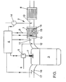
- the drawing shows the absorber in an exhaust system of an internal combustion engine.
- An absorber 1 is seated in an exhaust line 2 of an internal combustion engine 3, the operation of which is controlled by an engine management system.
- the engine management 4 acts on an injection pump 5, which conveys fuel from a tank 6 (not shown) to an injection nozzle 7.
- the most diverse leading to the engine management 4 common supply and discharge lines are not shown.
- a three-way catalyst 8 is arranged downstream of the absorber 1 in the exhaust line 2, and an arrangement of the three-way catalyst 8 upstream of the absorber 1 is also possible.
- the absorber 1 is composed of two metal foils, one of which is corrugated with a smooth foil (soldered to the wave crests). By rolling this multilayer film to obtain a cylindrical body having a plurality of axially extending channels in it. Furthermore, the carrier body of the absorber in a Central region 15 is rotated about its longitudinal axis, so that here the individual channels 16 narrowed and wound. A similarly acting turbulence-forming structure can also be achieved with a transverse undulation in one or both of the metal foils.
- the metal foil contains a few percent of aluminum and is oxidized so that a washcoat containing ⁇ -aluminum oxide adheres better to the metal foil.
- the Aluminiumoxidwashcoat also contains the elements sodium, barium, cerium and lanthanum, which are grown as salts (nitrates, oxides, hydroxides) on the alumina.
- the absorber is obtained.
- the absorber is impregnated with a platinum and rhodium-containing solution (in addition to or instead of rhodium, the solution may also contain palladium), from which then the corresponding precious metals are released as such.
- This noble metal coating corresponds to a three-way catalyst coating.
- the absorber thus obtained is electrically contacted and inserted into a housing so that a current flow through it to ground (the housing) is possible.
- the electrical contact 9 is connected at the other end to the controller 4.
- a temperature sensor 10 is used in the carrier body, which also leads to the controller 4.
- a broadband lambda probe 11 is inserted into the exhaust pipe, which in turn passes on its values proportional to the oxygen concentration present in the exhaust gas flow to the controller 4.
- a fuel injection 12 is provided upstream of the lambda probe 11, which is supplied in accordance with control commands from the controller 4 with fuel.
- an air injector 13 is provided which receives air from a pump 14 controlled by the controller 4.
- the internal combustion engine 3 is of a direct injection diesel engine type whose exhaust gas flow normally has a high oxygen excess and a temperature around 200 ° C to 400 ° C.
- nitrogen oxides present in the exhaust gas and oxides of sulfur are incorporated in the absorption layer of the absorber 1, with any oxidizable constituents (usually hydrocarbons) being oxidized at the same time by the noble metal coating of the absorber 1.
- the absorber Upon reaching the Saturation limit or at predetermined time intervals (other control variables are possible, such as a NOx determination in the exhaust gas after the absorber) is the absorber to regenerate ie free from the stored example as barium nitrate NOx.
- barium sulfate embedded oxides of sulfur can be removed in this case.
- it is checked by the control unit 4 via the temperature sensor 10, whether the temperature of the absorber coating for a regeneration is high enough.
- the temperature is below 500 ° C
- fuel is injected via the fuel injection 12 into the exhaust gas stream, which catalytically burns with the oxygen present in the exhaust gas stream at the noble metal coating of the absorber 1, thereby increasing its temperature.
- the metallic carrier body of the absorber 1 can be electrically heated by a current flow (by 9) (other temperature increases, such as an inductive heating of the metallic carrier body and / or a Abgasdrosselung are possible).
- a rich mixture is set in the exhaust gas, ie further fuel (over 12) injected.
- a throttle 17 is advantageously closed via the controller 4 in the intake passage 16 of the internal combustion engine 3, so that less air enters the internal combustion engine 3. This reduces the proportion of oxygen in the exhaust gas flow in such a way that the NOx and SOx are released from the absorption layer and the NOx is also reduced immediately.
- the end of the regeneration can be time-controlled but also controlled, for example, via the exothermic nature of the reaction temperature.
- the regeneration as in the DE 43 42 062 A described, carried out, that is, the exhaust stream is throttled before the absorber and in particular passed into a bypass to the absorber.
- the air injection 13 is provided, which is put into operation by the control 4 during the fuel injection (via 12). As a result, any remaining hydrocarbons are oxidized in the downstream catalyst 8 to carbon dioxide and water.
- the structure can be taken in principle, in direct-injection gasoline engines, the throttling 17 as Also, the fuel injection 12 omitted, since here on the fuel injection 7 into the combustion chamber of the internal combustion engine without difficulty sufficient enrichment of the exhaust gas flow can be achieved. Basically, however, the operation is possible here as in a diesel engine.
Description
Die Erfindung betrifft ein Verfahren zur Steuerung einer Verbrennungskraftmaschine.The invention relates to a method for controlling an internal combustion engine.
Aus der
Ein solcher Speicherkatalysator ist in der
Aus dem Dokument
Ferner ist aus dem Dokument
In dem Dokument
Ferner ist aus dem Dokument
Aus dem Dokument
Aus der
Aufgabe der Erfindung ist es, das aus dem Stand der Technik bekannte Verfahren dahingehend zu verbessern, dass zum einen der Trägerkörper die starken Temperaturänderungen, die beim Erhitzen und Abkühlen des Absorbers auftreten, besonders rasch durchläuft, und dass zum anderen eine besonders hohe Speicherkapazität der Absorptionsschicht erzielbar ist. Es versteht sich von selbst, dass gleichzeitig eine gute thermische und chemische Lengzeitstabilität des NOx-Absorbers gewährleistet sein muss.The object of the invention is to improve the known from the prior art method in that on the one hand, the strong body temperature changes that occur during heating and cooling of the absorber, passes through very quickly, and on the other hand, a particularly high storage capacity the absorption layer is achievable. It goes without saying that at the same time a good thermal and chemical Leng time stability of the NOx absorber must be guaranteed.
Die Aufgabe wird erfindungsgemäß mit den Merkmalen der unabhängigen Patentansprüche gelöst.The object is achieved with the features of the independent claims.
Die Unteransprüche zeigen bevorzugte Ausführungsformen, mit denen insbesondere auch bei sehr niedrigen Abgastemperaturen, wie sie beispielsweise bei direkteinspritzenden Dieselverbrennungskraftmaschinen vorliegen, ein Regenerieren des Absorbers ermöglicht ist.The subclaims show preferred embodiments, with which a regeneration of the absorber is made possible, in particular even at very low exhaust gas temperatures, as present, for example, in direct-injection diesel internal combustion engines.
Erfindungsgemäß können die üblichen absorbierenden Materialien eingesetzt werden, wie sie beispielsweise in der
Die bevorzugten NOx-Speichermaterialien zeichnen sich also dadurch aus, daß sie unter nettooxidierenden Bedingungen (stöchiometrischer Überschuß an Oxidationsmitteln), wie sie im Abgas von Mager-Motoren vorliegen, Stickoxide Zwischenspeichern und bei einer Verringerung des Sauerstoffüberschusses reduzieren können. Hierzu sind die NOx-Speicherkatalysatoren üblicherweise auch edelmetallbeschichtet, insbesondere mit den üblichen Edelmetallbeschichtungen für Dreiwegekatalysatoren. Die Regeneration des mit NOx beladenen Speichermaterials erfolgt dann vorteilhaft bei λ ≤ 1 in einer Regenerierphase.The preferred NOx storage materials are thus characterized by the fact that they can under nitrogen oxidizing conditions (stoichiometric excess of oxidizing agents), such as those present in the exhaust gas from lean-burn engines, reduce nitrogen oxide caching and a reduction in excess oxygen. For this purpose, the NOx storage catalysts are usually also noble metal coated, in particular with the usual noble metal coatings for three-way catalysts. The regeneration of the NOx-laden storage material is then advantageously at λ ≤ 1 in a regeneration phase.
Üblicherweise laufen an den NOx-Speicherkatalysatoren verschiedene Reaktionen nacheinander bis gleichzeitig ab, wobei die wichtigsten Reaktionen
- Oxidation des NO im Abgas zur NO2
- Speicherung des NO2 als Nitrat
- Zersetzung des Nitrats
- Reduktion des zurückgebildeten NO2 zu Stickstoff und Sauerstoff
- Oxidation of the NO in the exhaust gas to NO 2
- Storage of NO 2 as nitrate
- Decomposition of the nitrate
- Reduction of the reformed NO 2 to nitrogen and oxygen
Wie oben beschrieben, ist der Verlauf der Reaktionen unter anderem abhängig von der Temperatur des Katalysators, aber auch von der Konzentration der Reaktionspartner am aktiven Zentrum des Katalysators und der Strömungsgeschwindigkeit des Gases.As described above, the course of the reactions depends inter alia on the temperature of the catalyst, but also on the concentration of the reactants at the active center of the catalyst and the flow rate of the gas.
Erfindungsgemäß hat es sich nun gezeigt, daß mit verschiedenen Faktoren, die miteinander kombinierbar sind, es auch mit nur geringem Aufwand möglich ist, die bekannten Abgasabsorber zu optimieren, so daß sie insbesondere für direkteinspritzende Verbrennungskraftmaschinen und Dieselbrennkraftmaschinen eingesetzt werden können. Die wesentlichen Merkmale sind hierbei:
- Verringerung der Wandstärke des Trägerkörpers, auf dem die Absorptionsschicht aufgebracht ist, auf ≤ 160 µm, insbesondere ≤ 140 µm;
- Verwendung von Metallträgern, vorteilhaft mit einer Wandstärke ≤ 50 µm, vorzugsweise ≤ 40 µm und insbesondere ≤ 30 µm; und/oder
- Heizen des Absorbers auf eine Temperatur oberhalb der Temperatur des Abgasstromes.
- Reducing the wall thickness of the carrier body, on which the absorption layer is applied, to ≦ 160 μm, in particular ≦ 140 μm;
- Use of metal supports, advantageously with a wall thickness ≤ 50 μm, preferably ≤ 40 μm and in particular ≤ 30 μm; and or
- Heating the absorber to a temperature above the temperature of the exhaust stream.
Erfindungsgemäß hat es sich gezeigt, daß bei der Verwendung dünnwandiger keramischer Träger für die Absorptionsschicht, d. h. insbesondere von Trägerkörpern mit einer Wandstärke ≤ 0,14 mm, nicht nur ein schnellerer Temperaturanstieg der Absorptionsschicht möglich ist, sondern auch eine dickere Absorptionsschicht eingesetzt werden kann. Hierdurch wird zweierlei erreicht: zum einen können auch kurze Hochtemperaturphasen zum Regenerieren ausgenutzt werden, da die Speicherschicht schneller die höhere Temperatur annimmt, und zum anderen kann durch Auftragen einer dickeren Absorptionsschicht eine höhere Speicherkapazität erreicht werden, so daß über die längere Speicherfähigkeit des Absorbers beim Betrieb der Verbrennungskraftmaschine eine längere Zeitspanne verstreichen kann, bis der Speicher zu Regenerieren ist, so daß trotz der seltener auftretenden Temperaturspitzen im Abgasstrom von verbrauchsoptimierten Verbrennungskraftmaschinen kein Durchschlagen des Speichers (Erreichen der Sättigungsgrenze) erfolgt.According to the invention it has been found that when using thin-walled ceramic support for the absorption layer, ie in particular of support bodies with a wall thickness ≤ 0.14 mm, not only a faster increase in temperature of the absorption layer is possible, but also a thicker absorption layer can be used. This achieves two things: on the one hand, even short high-temperature phases can be utilized for regeneration, since the storage layer assumes the higher temperature more quickly, and, on the other hand, a higher storage capacity can be achieved by applying a thicker absorption layer, so that over the longer Storage capacity of the absorber during operation of the internal combustion engine can pass a longer period of time until the memory is to regenerate, so that despite the more rarely occurring temperature peaks in the exhaust gas flow of consumption-optimized internal combustion engines, no breakthrough of the memory (reaching the saturation limit).
Erfindungsgemäß sind insbesondere Absorber mit einem Trägerkörper aus Metallfolie geeignet, wobei die Metallfolie vorteilhaft noch als Widerstandsheizung geschaltet werden kann, so daß auch bei niedrigen Abgastemperaturen der Absorber auf die notwendige Regenerationstemperatur durch Leiten eines elektrischen Stromes durch den Metallträgerkörper gebracht werden kann. Außerdem lassen sich bei der Verwendung eines Metallträgerkörpers die Kanäle, die mit der Absorptionsschicht beschichtet sind, unterschiedlich gestalten, so daß beispielsweise eine Verwirbelung (turbulente Strömung) des Abgasstromes in den Kanälen gezielt einstellbar ist.According to the invention absorbers are particularly suitable with a support body of metal foil, wherein the metal foil can be advantageously switched as resistance heating, so that even at low exhaust gas temperatures of the absorber can be brought to the necessary regeneration temperature by passing an electric current through the metal support body. In addition, when using a metal carrier body, the channels that are coated with the absorption layer, make different, so that, for example, a turbulence (turbulent flow) of the exhaust stream is selectively adjustable in the channels.
Besonders vorteilhaft werden erfindungsgemäß für den Absorber Trägerkörper mit unterschiedlichen Kanalabschnitten eingesetzt, wobei z. B. ein mittlerer Bereich der Kanäle zur Erzielung einer turbulenten Strömung verändert ist. Dies ist beispielsweise durch eine Veränderung des Kanalquerschnitts oder aber durch eine Verdrehung bzw. Verwindung der Kanäle möglich. Hierdurch läßt sich der Trägerkörper gezielt für besonders günstige Reaktionsbedingungen entlang der Strömungskanäle anpassen. Eine weitere Besonderheit des Trägerkörpers ist neben der möglichen unterschiedlichen Zahl an Kanälen in Strömungsrichtung und dem Einbringen von Querschnittsänderungen entlang der Strömungsrichtung auch das Segmentieren des Trägerkörpers, wobei z. B. ein Segment mit Absorptionsschicht nahe des Motorauslasses und ein weiteres Segment mit Absorptionsschicht etwas entfernter angeordnet wird. Hierdurch lassen sich auch bei unterschiedlichsten Fahrbedingungen auch bei verbrauchsoptimierten Motoren gute NOx-Reinigungswerte erzielen.Particularly advantageous according to the invention for the absorber carrier body with different channel sections are used, wherein z. B. a central region of the channels to achieve a turbulent flow is changed. This is possible, for example, by changing the channel cross-section or by twisting or twisting the channels. As a result, the carrier body can be adjusted specifically for particularly favorable reaction conditions along the flow channels. Another special feature of the carrier body is in addition to the possible different number of channels in the flow direction and the introduction of cross-sectional changes along the flow direction and the segmentation of the carrier body, wherein z. B. a segment with absorption layer near the motor outlet and another segment with absorption layer is arranged slightly more remote. As a result, good NOx cleaning values can be achieved even in fuel-optimized engines, even under very different driving conditions.
Erfindungsgemäß hat es sich gezeigt, daß der NOx-Speicher besonders gute Absorptions-und Desorptionseigenschaften hat, wenn die Strömungskanäle für das Abgas in einem mittleren Bereich zur Erzielung einer turbulenten Strömung verwirbelt sind, wohingegen der Einlaßbereich und der Auslaßbereich nicht diese eine turbulente Strömung besonders begünstigende Struktur haben. Als einfachstes Mittel zur Erzeugung einer solchen turbulenten Strömung ist beispielsweise ein Übergang von einem großen zu einem kleinen Durchmesser in den Kanälen, jedoch auch eine Verdrehung des gesamten Körpers in diesem Bereich ist geeignet zur Erzeugung der Turbulenzen. Die besonders günstigen Eigenschaften werden vermutlich durch eine Trennung der einzelnen Reaktionsschritte zur Stickoxidreduktion auf einzelne Segmente des Trägerkörpers erreicht, wobei der veränderte mittlere Bereich gegenüber dem unveränderten mittleren Bereich bessere Reaktionsbedingungen gewährleistet.According to the invention, it has been found that the NO x storage has particularly good absorption and desorption properties when the flow channels for the exhaust gas are swirled in a central region to achieve a turbulent flow, whereas the inlet region and the outlet region do not particularly favor this turbulent flow Have structure. As the simplest means of producing such turbulent flow is, for example, a transition from a large to a small diameter in the channels, but also a rotation of the entire body in this area is suitable for generating the turbulence. The particularly favorable properties are presumably achieved by a separation of the individual reaction steps for the reduction of nitrogen oxides to individual segments of the carrier body, wherein the changed middle range guarantees better reaction conditions compared to the unchanged middle range.
Für die Erzielung besonders guter Umsätze hat die Absorptionsschicht eine vergrößerte Oberfläche von mindestens 20 m2/g, insbesondere mindestens 40 m2/g. Vorteilhaft hat die Absorptionsschicht vorzugsweise ein Porenvolumen von mindestens 0,2 cm3/g und insbesondere mindestens 0,4 cm3/g, wobei auch eine bimodale Porengrößenverteilung geeignet ist mit Mikroporen und Makroporen. Dies wird beispielsweise durch die Wahl einer bestimmten Partikelgröße für die Bildung der Absorberoberfläche erreicht, wobei auch Mischungen oder bestimmte Verteilungen unterschiedlicher Partikelgrößen geeignet sind.To achieve particularly good conversions, the absorption layer has an increased surface area of at least 20 m 2 / g, in particular at least 40 m 2 / g. Advantageously, the absorption layer preferably has a pore volume of at least 0.2 cm 3 / g and in particular at least 0.4 cm 3 / g, wherein a bimodal pore size distribution is also suitable with micropores and macropores. This is achieved, for example, by the choice of a specific particle size for the formation of the absorber surface, wherein mixtures or specific distributions of different particle sizes are also suitable.
Als Absorptionsoberfläche eignet sich insbesondere γ-Aluminiumoxid, das mit einem oder mehreren Elementen aus der Gruppe der Alkalimetalle, Erdalkalimetalle, seltenen Erden und/oder Lanthan beladen ist. Auch Kupfer und Mangan sind geeignete Elemente. Die Elemente liegen üblicherweise als Oxid, aber auch als Carbonat oder Nitrat vor, wobei die Speicherwirkung durch Bildung entsprechender Nitrate und Sulfate erzielt wird, die dann unter den entsprechenden Reaktionsbedingungen wieder zu Oxiden oder Carbonaten überführt werden. Hierdurch ist es möglich, NOx und/oder SOx insbesondere aus einem Abgas, das mindestens 1 % Sauerstoff enthält, zu absorbieren.The absorption surface is in particular γ-alumina, which is loaded with one or more elements from the group of alkali metals, alkaline earth metals, rare earths and / or lanthanum. Copper and manganese are also suitable elements. The elements are usually present as oxide, but also as carbonate or nitrate, wherein the storage effect is achieved by forming corresponding nitrates and sulfates, which are then converted under the appropriate reaction conditions again to oxides or carbonates. This makes it possible to absorb NOx and / or SOx in particular from an exhaust gas containing at least 1% oxygen.
Wie beschrieben, werden die absorbierten Stoffe insbesondere durch erhöhte Temperaturen und in reduzierender Atmosphäre wieder freigesetzt. Hierzu ist es vorteilhaft, wenn im Abgas die Sauerstoffkonzentration ermittelt wird, wobei dann die Sauerstoffkonzentration oder eine mit der Sauerstoffkonzentration in bekannter Beziehung stehende Größe zur Steuerung des Absorptions- bzw. Desorptionsvorganges herangezogen werden kann. Entsprechendes gilt auch für die Temperatur des Abgasstroms, wobei entscheidend die Temperatur der Absorptionsschicht ist, die unmittelbar oder mittelbar bestimmt wird. So kann die Temperatur beispielsweise durch Messung der Temperatur des Abgasstroms bzw. des Trägerkörpers gemessen werden; auch eine Temperaturbestimmung über ein Kennfeld der Verbrennungskraftmaschine ist möglich.As described, the absorbed substances are released in particular by increased temperatures and in a reducing atmosphere. For this purpose, it is advantageous if the oxygen concentration is determined in the exhaust gas, in which case the oxygen concentration or a quantity in known relationship with the oxygen concentration can be used to control the absorption or desorption process. The same applies to the temperature of the exhaust gas stream, wherein the temperature of the absorption layer is decisive, which is determined directly or indirectly. Thus, the temperature can be measured for example by measuring the temperature of the exhaust stream or the carrier body; It is also possible to determine the temperature via a characteristic map of the internal combustion engine.
Mit der vorliegenden Erfindung lassen sich Absorptionsschichten in einer Dicke von mindestens 50 µm, insbesondere mindestens 70 µm und besonders vorteilhaft mindestens 90 µm herstellen (durchschnittliche Schichtdicke eines Querschnitts; Werte gelten für Keramik, bei Metall gelten die halben Werte) wobei sich diese Schichtdicke der Absorptionsschicht über vorzugsweise mindestens 50 % und insbesondere mindestens 80 % des Absorbers erstreckt. Solche Schichtdicken ermöglichen gegenüber den herkömmlichen Absorbern eine höhere Speicherkapazität und damit die oben beschriebenen längeren Intervalle bis zur Regeneration.With the present invention it is possible to produce absorption layers in a thickness of at least 50 μm, in particular at least 70 μm and particularly advantageously at least 90 μm (average layer thickness of a cross section, values apply to ceramics, in the case of metal the half values apply), whereby this layer thickness of the absorption layer preferably over at least 50% and in particular at least 80% of the absorber extends. Such layer thicknesses allow a higher storage capacity compared with the conventional absorbers and thus the longer intervals described above until regeneration.
Gemäß dem mit zur Erfindung gehörenden Verfahren kann das Regenerieren vorteilhaft dann erfolgen, wenn die Betriebsbedingungen der Verbrennungskraftmaschine eine entsprechend hohe Temperatur des Abgasstroms und damit der Absorptionsschicht bewirken. Ganz besonders vorteilhaft ist jedoch eine erfindungsgemäße Verfahrensweise, bei der eine Zusatzheizung der Absorptionsschicht vorgesehen ist, die insbesondere elektrisch erfolgt. Andere Beheizungsmaßnahmen sind Zündungsmaßnahmen (bei Otto-Motoren), Veränderung des λ, Absenken des λ, auf < 1 und Senkundärluftzugabe zum Erzeugen von Exothermie an einem Oxidationskatalysator bzw. über eine Zündeinrichtung sowie Beheizen des Katalysators durch einen Brenner. Besonders vorteilhaft ist hierbei wieder ein segmentierter Absorber, der dann reaktionsspezifisch beheizt wird. So kann beispielsweise nur ein stromabwärts angeordneter Absorberbereich beheizt werden, insbesondere bei einer deutlichen räumlichen Trennung der Absorbersegmente (siehe oben). Auch hier ist die elektrische Beheizung wieder besonders vorteilhaft, aber auch eine Kraftstoffeinspritzung in den Abgasstrom bzw. ein Brenner. Durch die Anordnung einzelner Segmente für Einzelreaktionen in unterschiedlichem Abstand zum Auslaßventil in motornaher und motorferner Position läßt sich außerdem eine thermische Alterung des Absorbers vermindern (neben dem Vorteil der besonders günstigen Reaktionstemperaturen in einzelnen Absorberbereichen).According to the method associated with the invention, the regeneration can advantageously take place when the operating conditions of the internal combustion engine cause a correspondingly high temperature of the exhaust gas stream and thus of the absorption layer. However, a procedure according to the invention in which an additional heating of the absorption layer is provided, which in particular takes place electrically, is very particularly advantageous. Other heating measures are ignition measures (in gasoline engines), changing the λ, lowering the λ, to <1 and Senkundärluftzugabe to produce exothermic oxidation of an oxidation catalyst or via an ignition device and heating the catalyst by a burner. Particularly advantageous here again is a segmented absorber, which is then heated reaction-specific. For example, only one absorber area arranged downstream can be heated, in particular if there is a clear spatial separation of the absorber segments (see above). Again, the electric heating is particularly advantageous again, but also a fuel injection into the exhaust stream or a burner. By arranging individual segments for individual reactions at different distances from the outlet valve in the position close to the engine and remote from the engine, thermal aging of the absorber can also be reduced (in addition to the advantage of particularly favorable reaction temperatures in individual absorber regions).
Ferner kann über die Beheizung des Absorbers (insbesondere elektrisch oder mittels eines Brenners) eine Rußablagerung am Absorber aufgelöst werden, die ansonsten die Speicherfähigkeit deutlich herabsetzen würde. Hierzu wird vorzugsweise die Einstellung von λ ≤ 1 im Abgasstrom erst nach einem Abbrennen des Russes vorgenommen.Furthermore, via the heating of the absorber (in particular electrically or by means of a burner) a soot deposit on the absorber can be dissolved, which otherwise the Storage ability would significantly reduce. For this purpose, the setting of λ ≦ 1 in the exhaust gas flow is preferably carried out only after a burning of the soot.
Da für die Freisetzung und Umsetzung des NOx aus dem Speicher und die Freisetzung der Schwefeloxide aus dem Speicher unterschiedliche Temperaturen notwendig sind (beim letzteren höhere), kann außerdem so verfahren werden, daß eine Desorption der Schwefeloxide (die insbesondere als Sulfat vorliegen) in größeren Zeitspannen bzw. bei Bedarf vorgenommen wird, so daß der Speicher nur gelegentlich auf die hohen Temperaturen erhitzt wird, die für eine Desorption der Schwefeloxide notwendig sind. Auch hierdurch wird einer frühzeitigen Alterung des Speichers entgegengewirkt, so daß eine besonders gute Langzeitstabilität des Absorbers erreicht wird. Im übrigen bedient sich das Verfahren der oben bei dem Absorber und im Ausführungsbeispiel beschriebenen Maßnahmen, wie auch die beim Verfahren und im Ausführungsbeispiel beschriebenen Merkmale bei dem eingangs beschriebenen Absorber eingesetzt werden können.Since different temperatures are necessary for the release and conversion of the NOx from the storage tank and the release of the sulfur oxides from the storage tank (higher for the latter), it is also possible to carry out a desorption of the sulfur oxides (which are present in particular as sulfate) in relatively long periods or is made as needed, so that the memory is heated only occasionally to the high temperatures that are necessary for a desorption of the sulfur oxides. This also counteracts premature aging of the reservoir, so that a particularly good long-term stability of the absorber is achieved. Moreover, the method uses the measures described above in the absorber and in the embodiment, as well as the features described in the method and in the embodiment can be used in the absorber described above.
Die Erfindung wird im folgenden anhand eines Ausführungsbeispiels und einer Zeichnung näher beschrieben.The invention will be described in more detail below with reference to an embodiment and a drawing.
Die Zeichnung zeigt den Absorber in einem Abgassystem einer Brennkraftmaschine.The drawing shows the absorber in an exhaust system of an internal combustion engine.
Ein Absorber 1 sitzt in einem Abgasstrang 2 einer Verbrennungskraftmaschine 3, deren Betrieb über ein Motormanagement gesteuert wird. Das Motormanagement 4 wirkt hierzu auf eine Einspritzpumpe 5, die Kraftstoff von einem (nicht dargestellten) Tank 6 zu einer Einspritzdüse 7 fördert. Übersichtshalber sind die verschiedensten zu dem Motormanagement 4 führenden üblichen Zu- und Ableitungen nicht dargestellt.An absorber 1 is seated in an exhaust line 2 of an internal combustion engine 3, the operation of which is controlled by an engine management system. For this purpose, the
In dem Abgasstrang 2 ist ferner noch ein Dreiwegekatalysator 8 stromabwärts von dem Absorber 1 angeordnet, auch eine Anordnung des Dreiwegekatalysators 8 stromaufwärts des Absorbers 1 ist möglich.In addition, a three-way catalyst 8 is arranged downstream of the absorber 1 in the exhaust line 2, and an arrangement of the three-way catalyst 8 upstream of the absorber 1 is also possible.
Der Absorber 1 ist aus zwei Metallfolien aufgebaut, von denen die eine gewellt mit einer glatten Folie verbunden (an den Wellenbergen verlötet) ist. Durch Zusammenrollen dieser mehrlagigen Folie erhält man einen zylindrischen Körper mit einer Vielzahl von sich in ihm axial erstreckenden Kanälen. Ferner wurde der Trägerkörper des Absorbers in einem mittleren Bereich 15 um seine Längsachse gedreht, so daß hier die einzelnen Kanäle 16 verengt und gewunden sind. Eine ähnlich wirkende Turbulenzen bildende Struktur läßt sich auch mit einer Querwellung in einer oder beiden der Metallfolien erreichen.The absorber 1 is composed of two metal foils, one of which is corrugated with a smooth foil (soldered to the wave crests). By rolling this multilayer film to obtain a cylindrical body having a plurality of axially extending channels in it. Furthermore, the carrier body of the absorber in a
Die Metallfolie enthält wenige Prozent Aluminium und wird anoxidiert, damit ein γ-aluminiumoxidhaltiger washcoat besser auf der Metallfolie haftet. Der Aluminiumoxidwashcoat enthält ferner die Elemente Natrium, Barium, Cer und Lanthan, die als Salze (Nitrate, Oxide, Hydrooxide) auf das Aluminiumoxid aufgezogen sind. Durch Tränken des gewickelten Trägerkörpers mit dem washcoat und anschließendes Brennen erhält man den Absorber. Zusätzlich wird der Absorber mit einer platin- und rhodiumhaltigen Lösung (zusätzlich oder anstatt des Rhodiums kann die Lösung auch Palladium enthalten) getränkt, aus der dann die entsprechenden Edelmetalle als solche freigesetzt werden. Diese Edelmetallbeschichtung entspricht einer Dreiwegekatalysator-Beschichtung. Der so erhaltene Absorber wird elektrisch kontaktiert und so in ein Gehäuse eingesetzt, daß ein Stromfluß durch ihn gegen Masse (das Gehäuse) möglich ist. Die elektrische Kontaktierung 9 ist anderenends mit der Steuerung 4 verbunden. Außerdem ist in den Trägerkörper noch ein Temperaturfühler 10 eingesetzt, der ebenfalls zu der Steuerung 4 führt.The metal foil contains a few percent of aluminum and is oxidized so that a washcoat containing γ-aluminum oxide adheres better to the metal foil. The Aluminiumoxidwashcoat also contains the elements sodium, barium, cerium and lanthanum, which are grown as salts (nitrates, oxides, hydroxides) on the alumina. By impregnating the wound carrier body with the washcoat and then firing, the absorber is obtained. In addition, the absorber is impregnated with a platinum and rhodium-containing solution (in addition to or instead of rhodium, the solution may also contain palladium), from which then the corresponding precious metals are released as such. This noble metal coating corresponds to a three-way catalyst coating. The absorber thus obtained is electrically contacted and inserted into a housing so that a current flow through it to ground (the housing) is possible. The electrical contact 9 is connected at the other end to the
Stromaufwärts von dem Absorber 1 ist eine Breitbandlambdasonde 11 in das Abgasrohr eingesetzt, die wiederum ihre der im Abgasstrom vorliegenden Sauerstoffkonzentration proportionalen Werte an die Steuerung 4 weitergibt. Außerdem ist stromaufwärts der Lambdasonde 11 eine Kraftstoffeinspritzung 12 vorgesehen, die entsprechend von Steuerbefehlen aus der Steuerung 4 mit Kraftstoff versorgt wird. Zwischen dem Absorber 1 und dem nachgeschalteten Katalysator 8 ist eine Lufteindüsung 13 vorgesehen, die Luft von einer von der Steuerung 4 gesteuerten Pumpe 14 erhält.Upstream of the absorber 1, a
Die Verbrennungskraftmaschine 3 ist vom Typ eines direkteinspritzenden Dieselmotors, dessen Abgasstrom normalerweise einen hohen Sauerstoffüberschuß und eine Temperatur um 200 °C bis 400 °C hat.The internal combustion engine 3 is of a direct injection diesel engine type whose exhaust gas flow normally has a high oxygen excess and a temperature around 200 ° C to 400 ° C.
Im Betrieb der Brennkraftmaschine werden im Abgas vorhandene Stickoxide und Oxide des Schwefels in der Absorptionsschicht des Absorbers 1 eingelagert, wobei gleichzeitig eventuell vorhandene oxidierbare Bestandteile (meist Kohlenwasserstoffe) durch die Edelmetallbeschichtung des Absorbers 1 oxidiert werden. Bei Erreichen der Sättigungsgrenze oder aber in vorbestimmten Zeitintervallen (auch andere Steuerungsgrößen sind möglich, wie beispielsweise eine NOx-Bestimmung im Abgas nach dem Absorber) ist der Absorber zu regenerieren d. h. von dem beispielsweise als Bariumnitrat eingelagerten NOx zu befreien. Gleichzeitig können hierbei auch (beispielsweise als Bariumsulfat) eingelagerte Oxide des Schwefels entfernt werden. Hierzu wird von dem Steuergerät 4 über den Temperaturfühler 10 geprüft, ob die Temperatur der Absorberbeschichtung für ein Regenerieren hoch genug ist. Sofern die Temperatur unter 500 °C liegt, wird über die Kraftstoffeindüsung 12 in den Abgasstrom Kraftstoff eingedüst, der mit dem im Abgasstrom vorhandenen Sauerstoff katalytisch an der Edelmetallbeschichtung des Absorbers 1 verbrennt, wodurch sich dessen Temperatur erhöht. Alternativ und/oder zusätzlich kann der metallische Trägerkörper des Absorbers 1 über einen Stromfluß (durch 9) elektrisch erhitzt werden (auch andere Temperaturerhöhungen, wie beispielsweise eine induktive Erhitzung des metallischen Trägerkörpers und/oder eine Abgasdrosselung sind möglich).During operation of the internal combustion engine, nitrogen oxides present in the exhaust gas and oxides of sulfur are incorporated in the absorption layer of the absorber 1, with any oxidizable constituents (usually hydrocarbons) being oxidized at the same time by the noble metal coating of the absorber 1. Upon reaching the Saturation limit or at predetermined time intervals (other control variables are possible, such as a NOx determination in the exhaust gas after the absorber) is the absorber to regenerate ie free from the stored example as barium nitrate NOx. At the same time (for example as barium sulfate) embedded oxides of sulfur can be removed in this case. For this purpose, it is checked by the
Sobald der Absorber 1 genügen erhitzt ist, wird ein fettes Gemisch im Abgas eingestellt, d. h. weiterhin Kraftstoff (über 12) eingedüst. Hierbei wird vorteilhaft im Ansaugkanal 16 der Brennkraftmaschine 3 eine Drossel 17 über die Steuerung 4 geschlossen, so daß weniger Luft in die Verbrennungskraftmaschine 3 gelangt. Hierdurch reduziert sich der Sauerstoffanteil im Abgasstrom derart, daß das NOx und SOx aus der Absorptionsschicht freigegeben und das NOx auch gleich reduziert wird. Das Ende des Regenerierens kann zeitgesteuert ablaufen aber auch beispielsweise über die Exothermie der Reaktionstemperatur kontrolliert. In einer weiteren Ausgestaltung kann das Regenerieren, wie in der
Um eventuell noch vorhandene Kohlenwasserstoffe abzubauen, ist nach dem Absorber 1 die Lufteindüsung 13 vorgesehen, die während der Kraftstoffeindüsung (über 12) von der Steuerung 4 in Betrieb gesetzt wird. Hierdurch werden eventuell noch vorhandene Kohlenwasserstoffe in dem nachgeschalteten Katalysator 8 zu Kohlendioxid und Wasser oxidiert.In order to reduce hydrocarbons which may still be present, after the absorber 1, the
Beim Einsatz einer Wirbelkammer-Dieselbrennkraftmaschine kann der Aufbau prinzipiell übernommen werden, bei direkteinspritzenden Otto-Motoren kann die Drosselung 17 wie auch die Kraftstoffeindüsung 12 entfallen, da hier über die Kraftstoffeinspritzung 7 in den Brennraum der Brennkraftmaschine ohne Schwierigkeiten eine genügende Anfettung des Abgasstromes erreicht werden kann. Grundsätzlich ist jedoch auch hier der Betrieb wie bei einer Dieselbrennkraftmaschine möglich.When using a vortex chamber diesel engine, the structure can be taken in principle, in direct-injection gasoline engines, the throttling 17 as Also, the
Da beim Regenerieren die Leistung der Brennkraftmaschine 3 vermindert sein kann, können Maßnahmen vorgesehen werden, daß bei einem völligen Durchtreten des Gasstellmittels für die Brennkraftmaschine das Regenerieren zumindest für einen gewissen Zeitraum unterdrückt wird.Since the power of the internal combustion engine 3 can be reduced during regeneration, measures can be taken to ensure that regeneration is suppressed at least for a certain period of time when the gas actuating means for the internal combustion engine completely passes through.
Claims (26)
- Method for operating an internal combustion engine, with the steps- operation of the internal combustion engine so as to form an oxygen-containing exhaust-gas stream;- storage of the NOx by the absorption layer;- heating of the absorption layer to a temperature of at least 500°C during the operation of the internal combustion engine before, simultaneously with or after the formation of a low-oxygen exhaust-gas stream or of an exhaust-gas stream having a stoichiometric excess of reducing agent;- desorption of the NOx by the reduction of the NOx in the low-oxygen exhaust-gas stream or in the exhaust-gas stream with a stoichiometric excess of reducing agent while the absorption layer has the temperature of at least 500°C;- reformation of an oxygen-containing exhaust-gas stream;- termination of the heating of the absorption layer to the temperature of at least 500°C before, simultaneously with or after the abovementioned step; and- repetition of the steps from storage of the NOx by the absorption layer,the internal combustion engine, in particular spark-ignition internal combustion engine or diesel internal combustion engine, comprising an exhaust tract (2) in which is arranged an absorber (1) with a carrier body to which is applied an absorption layer which, under net oxidizing conditions, such as prevail in the exhaust gas of lean-burn engines, can intermediately store nitrogen oxides (NOx) and, in the case of a reduction in the oxygen excess and with a temperature of at least 500°C, can reduce these, a ceramic carrier body with a wall thickness 0.14 mm being present.
- Method according to Claim 1, characterized in that the absorption layer releases sulphur oxides (SOx) at increased temperature.
- Method according to at least one of the preceding claims, characterized in that the absorption layer carries at least one noble metal.
- Method according to Claim 3, characterized in that the absorption layer having the noble metal forms an oxidizing catalyst or a three-way catalyst.
- Method according to at least one of the preceding claims, characterized in that the absorption layer is in a wash coat.
- Method according to at least one of the preceding claims, characterized in that the absorption layer has at least a thickness of 50 µm.
- Method according to Claim 6, characterized in that the layer thickness of the absorption layer extends over at least 50%, in particular at least 80%, of the absorber.
- Method according to Claim 7, characterized in that the carrier body contains flow ducts for the exhaust gas which have the absorption layer.
- Method according to Claim 8, characterized in that a plurality of the ducts have, at least over a portion, a structure which swirls the gas stream.
- Method according to Claim 9, characterized in that the structure swirling the gas stream is a change in cross section and/or a corrugation and/or a twisting or curving of the ducts.
- Method according to one of Claims 8 to 10, characterized in that the absorber is subdivided into segments.
- Method according to Claim 11, characterized in that the segments have different lengths and/or different duct cross sections and/or different numbers of ducts and/or are spaced at least 50 cm apart from one another.
- Method according to at least one of the preceding claims, characterized in that the absorber (1) has a surface with at least 20 m2/g, in particular at least 40 m2/g and especially advantageously at least 100 m2/g, with respect to that mass of the absorption layer which can be reached by the gas stream.
- Method according to at least one of the preceding claims, characterized in that the absorption layer contains an aluminium oxide, in particular γ-aluminium oxide.
- Method according to at least one of the preceding claims, characterized in that the absorption layer contains an element from the group of alkali metals, alkaline earth metals, rare earths, lanthanum, titanium, copper and/or manganese.
- Method according to Claim 15, characterized in that the absorption layer contains at least one of the elements barium, sodium or potassium.
- Method according to at least one of the preceding claims, characterized in that an oxygen concentration determination device, which determines the oxygen concentration or a variable containing the oxygen concentration, and a control device, which has the oxygen concentration or the variable containing this as an input variable and causes the absorber to be loaded and discharged, are provided.
- Method according to at least one of the preceding claims, characterized by a temperature determination device which determines the temperature or a variable containing the temperature of the gas stream and/or of the absorption layer and/or of the carrier body, and in that a control device is provided which has the temperature or the variable containing this as an input variable and causes the absorber to be loaded and discharged.
- Method according to Claim 18, characterized in that the control device has the oxygen concentration and the temperature or the variables containing these as input variables.
- Method according to at least one of the preceding claims, characterized in that the absorber (1) is preceded and/or followed by an oxidizing catalyst, in particular a three-way catalyst, as an independent unit.
- Method according to at least one of preceding claims, characterized in that the absorption layer has a pore volume of at least 0.2 cm3/g with respect to the mass which can be reached by the flow of the gas stream.
- Method according to one of the preceding claims, characterized in that the heating of the absorption layer is achieved by the injection of fuel into the exhaust-gas stream and, in particular, the catalytic combustion of the latter and/or by varying the operating state of the internal combustion engine and/or by the electrical heating of the absorption layer and/or by burner heating of the exhaust-gas stream.
- Method according to one of the preceding claims, characterized in that, before the step:- heating of the absorption layer at least to a temperature of at least 500°C during the operation of the internal combustion engine,a step:- determination of whether the absorption layer and/or an object standing in temperature relation to the absorption layer have/has the temperature of at least 500°C,is carried out, and in that the steps:- heating of the absorption layer to a temperature of at least 500°C during the operation of the internal combustion engine, and- termination of the heating of the absorption layer to a temperature of at least 500°C during the operation of the internal combustion engineare dispensed with when, during determination, it is established that the absorption layer and/or the object standing in temperature relation to the absorption layer have/has the temperature of at least 500°C.
- Method according to one of the preceding claims, characterized in that, in addition to NOx, at least one oxide of sulphur (SOx) is also stored or desorbed by the absorption layer during the method steps.
- Method according to one of the preceding claims, characterized in that the desorption takes place as a function of time and/or as a function of the load of the absorption layer.
- Method according to one of the preceding claims, characterized in that the exhaust-gas stream is led turbulently over the absorption layer.
Applications Claiming Priority (3)
| Application Number | Priority Date | Filing Date | Title |
|---|---|---|---|
| DE19633050 | 1996-08-19 | ||
| DE19633050 | 1996-08-19 | ||
| PCT/EP1997/004306 WO1998007504A1 (en) | 1996-08-19 | 1997-08-07 | NOx-ADSORBER |
Publications (2)
| Publication Number | Publication Date |
|---|---|
| EP0944428A1 EP0944428A1 (en) | 1999-09-29 |
| EP0944428B1 true EP0944428B1 (en) | 2013-06-26 |
Family
ID=7802797
Family Applications (1)
| Application Number | Title | Priority Date | Filing Date |
|---|---|---|---|
| EP97918968.5A Expired - Lifetime EP0944428B1 (en) | 1996-08-19 | 1997-08-07 | Method for operating an internal combustion engine with a NOx adsorber |
Country Status (5)
| Country | Link |
|---|---|
| US (2) | US6531099B1 (en) |
| EP (1) | EP0944428B1 (en) |
| JP (1) | JP2001503668A (en) |
| KR (1) | KR100494189B1 (en) |
| WO (1) | WO1998007504A1 (en) |
Families Citing this family (29)
| Publication number | Priority date | Publication date | Assignee | Title |
|---|---|---|---|---|
| DE59710447D1 (en) * | 1996-08-19 | 2003-08-21 | Volkswagen Ag | COMBINED IGNITION ENGINE WITH A NOx ADSORBER |
| JP3924946B2 (en) * | 1997-09-25 | 2007-06-06 | マツダ株式会社 | Exhaust gas purification material |
| DE19855089B4 (en) * | 1998-11-28 | 2008-09-04 | Volkswagen Ag | Sulfur trap for an exhaust gas purification system of an internal combustion engine and method for operating the sulfur trap |
| DE69808314T2 (en) * | 1998-12-15 | 2003-04-17 | Daimler Chrysler Ag | Emission control system with nitrogen oxide adsorber and operating method |
| US6273938B1 (en) * | 1999-08-13 | 2001-08-14 | 3M Innovative Properties Company | Channel flow filter |
| DE10040554B4 (en) * | 2000-08-15 | 2013-05-02 | Daimler Ag | Method for operating an exhaust gas purification system with particle filter and nitrogen oxide storage |
| JP4717269B2 (en) * | 2001-06-22 | 2011-07-06 | ボッシュ株式会社 | Diesel exhaust gas aftertreatment method and apparatus |
| US6618687B2 (en) * | 2001-10-16 | 2003-09-09 | The United States Of America As Represented By The Secretary Of The Navy | Temperature-based estimation of remaining absorptive capacity of a gas absorber |
| EP1857648B1 (en) * | 2001-12-03 | 2013-10-23 | International Engine Intellectual Property Company, LLC | System and methods for improving emission control of internal combustion engines |
| US7082753B2 (en) * | 2001-12-03 | 2006-08-01 | Catalytica Energy Systems, Inc. | System and methods for improved emission control of internal combustion engines using pulsed fuel flow |
| JP4291650B2 (en) * | 2003-09-03 | 2009-07-08 | トヨタ自動車株式会社 | Exhaust purification equipment |
| US7117669B2 (en) * | 2004-05-05 | 2006-10-10 | Eaton Corporation | Temperature swing adsorption and selective catalytic reduction NOx removal system |
| DE102005026036A1 (en) * | 2005-06-03 | 2006-12-07 | Emitec Gesellschaft Für Emissionstechnologie Mbh | Method and device for providing ammonia in an exhaust gas stream of an internal combustion engine |
| EP1893858B1 (en) * | 2005-06-22 | 2017-04-12 | Ricardo, Inc. | Reforming process for production of hydrogen from hydrocarbon fuel |
| US7663295B2 (en) * | 2005-12-15 | 2010-02-16 | Imec | Method and system for measuring physical parameters with a piezoelectric bimorph cantilever in a gaseous or liquid environment |
| US8870811B2 (en) * | 2006-08-31 | 2014-10-28 | Fresenius Medical Care Holdings, Inc. | Peritoneal dialysis systems and related methods |
| US7654079B2 (en) | 2006-11-07 | 2010-02-02 | Cummins, Inc. | Diesel oxidation catalyst filter heating system |
| US7707826B2 (en) | 2006-11-07 | 2010-05-04 | Cummins, Inc. | System for controlling triggering of adsorber regeneration |
| US7594392B2 (en) * | 2006-11-07 | 2009-09-29 | Cummins, Inc. | System for controlling adsorber regeneration |
| US7533523B2 (en) * | 2006-11-07 | 2009-05-19 | Cummins, Inc. | Optimized desulfation trigger control for an adsorber |
| US7654076B2 (en) * | 2006-11-07 | 2010-02-02 | Cummins, Inc. | System for controlling absorber regeneration |
| US8105541B2 (en) * | 2008-10-13 | 2012-01-31 | Pratt & Whitney Rocketdyne, Inc. | Reactor system and method therefore |
| CN102667460B (en) * | 2009-12-09 | 2014-09-03 | 丰田自动车株式会社 | Device for detecting sulfur component |
| US9115627B2 (en) * | 2012-07-06 | 2015-08-25 | Denso International America, Inc. | Multiple skewed channel bricks mounted in opposing clocking directions |
| US10081241B2 (en) | 2015-12-10 | 2018-09-25 | Curtis Alan Roys | Diesel fuel guard |
| CA3019170A1 (en) | 2016-04-08 | 2017-10-12 | Dan Warkander | Temperature-based estimation of scrubbing capacity of a gas scrubber |
| US11135345B2 (en) | 2017-05-10 | 2021-10-05 | Fresenius Medical Care Holdings, Inc. | On demand dialysate mixing using concentrates |
| US11504458B2 (en) | 2018-10-17 | 2022-11-22 | Fresenius Medical Care Holdings, Inc. | Ultrasonic authentication for dialysis |
| CN113880051B (en) * | 2021-10-20 | 2023-02-10 | 杭州博大净化设备有限公司 | Marine oxygenerator |
Family Cites Families (15)
| Publication number | Priority date | Publication date | Assignee | Title |
|---|---|---|---|---|
| US4755499A (en) | 1984-10-12 | 1988-07-05 | Noxso Corporation | Sorbent for removing nitrogen oxides, sulfur oxides and hydrogen sulfide from gas streams |
| US4849274A (en) * | 1987-06-19 | 1989-07-18 | W. R. Grace & Co.-Conn. | Honeycomb fluid conduit |
| CZ283018B6 (en) | 1991-02-01 | 1997-12-17 | Merck Sharp And Dohme Limited | Imidazole, triazole and tetrazole derivatives, process of their preparation, their use and pharmaceuticals based thereon |
| US5240682A (en) | 1991-05-06 | 1993-08-31 | W. R. Grace & Co.-Conn | Reinforced corrugated thin metal foil strip useful in a catalytic converter core, a catalytic converter core containing said strip and an electrically heatable catalytic converter containing said core |
| JP2783074B2 (en) | 1991-10-29 | 1998-08-06 | トヨタ自動車株式会社 | Exhaust gas purification device for internal combustion engine |
| JP2605586B2 (en) | 1992-07-24 | 1997-04-30 | トヨタ自動車株式会社 | Exhaust gas purification device for internal combustion engine |
| US5260035A (en) | 1992-08-05 | 1993-11-09 | Corning Incorporated | Apparatus and method for modifying gaseous mixtures |
| US5362463A (en) | 1992-08-26 | 1994-11-08 | University Of De | Process for removing NOx from combustion zone gases by adsorption |
| US5406790A (en) | 1992-12-11 | 1995-04-18 | Toyota Jidosha Kabushiki Kaisha | Exhaust gas purification device for an engine |
| JP2830669B2 (en) * | 1992-12-29 | 1998-12-02 | トヨタ自動車株式会社 | Exhaust gas purification device for internal combustion engine |
| US5451558A (en) | 1994-02-04 | 1995-09-19 | Goal Line Environmental Technologies | Process for the reaction and absorption of gaseous air pollutants, apparatus therefor and method of making the same |
| US5874153A (en) * | 1994-02-04 | 1999-02-23 | Emitec Gesellschaft Fuer Emissionstechnologie Mbh | Zeolite-coatable metallic foil process for producing the metallic foil |
| US5633217A (en) | 1994-09-12 | 1997-05-27 | Corning Incorporated | Method of making a high strength catalyst, catalyst support or adsorber |
| JP3358766B2 (en) * | 1994-12-16 | 2002-12-24 | トヨタ自動車株式会社 | Exhaust gas purification catalyst |
| JP3375790B2 (en) | 1995-06-23 | 2003-02-10 | 日本碍子株式会社 | Exhaust gas purification system and exhaust gas purification method |
-
1997
- 1997-08-07 JP JP51033998A patent/JP2001503668A/en not_active Ceased
- 1997-08-07 WO PCT/EP1997/004306 patent/WO1998007504A1/en active IP Right Grant
- 1997-08-07 KR KR10-1999-7000653A patent/KR100494189B1/en not_active IP Right Cessation
- 1997-08-07 EP EP97918968.5A patent/EP0944428B1/en not_active Expired - Lifetime
-
1999
- 1999-02-18 US US09/252,506 patent/US6531099B1/en not_active Expired - Lifetime
- 1999-05-19 US US09/314,204 patent/US6274106B1/en not_active Expired - Lifetime
Also Published As
| Publication number | Publication date |
|---|---|
| WO1998007504A1 (en) | 1998-02-26 |
| KR20000068020A (en) | 2000-11-25 |
| US6274106B1 (en) | 2001-08-14 |
| EP0944428A1 (en) | 1999-09-29 |
| JP2001503668A (en) | 2001-03-21 |
| KR100494189B1 (en) | 2005-06-10 |
| US6531099B1 (en) | 2003-03-11 |
Similar Documents
| Publication | Publication Date | Title |
|---|---|---|
| EP0944428B1 (en) | Method for operating an internal combustion engine with a NOx adsorber | |
| EP0930930B1 (en) | PROCESS FOR REMOVING NOx FROM EXHAUST FUMES | |
| EP1342496B1 (en) | Spark-ignited internal combustion engine with an NOx-adsorber | |
| EP0829623B1 (en) | Process for reducing NOx emission from exhaust gases | |
| EP1600612B1 (en) | Process for separating nitrogen oxides and soot particles from a lean exhaust gas from a combustion engine and exhaust gas cleaning system therefor | |
| WO2000064566A1 (en) | System for purifying exhaust gases of an internal combustion engine and method for operating such a system | |
| EP0945608A2 (en) | Process for operating an exhaust gas purification apparatus comprising a sulfur-trap and a nitrogen oxide storage catalytic converter | |
| WO1999022129A1 (en) | Method for operating a piston internal combustion engine with direct fuel injection and secondary treatment of exhaust | |
| EP2266681A1 (en) | Exhaust gas system having a reducing agent supply unit, a filter element and a SCR-catalyst | |
| EP3126646B1 (en) | Regeneration method for exhaust-gas aftertreatment systems | |
| WO2009059679A1 (en) | Internal combustion engine with exhaust gas system | |
| EP0925431B1 (en) | Exhaust fume purification process for an internal combustion engine | |
| DE19636041A1 (en) | Waste gas purification process | |
| DE69838165T2 (en) | Method for producing a NOx purification catalyst and device for purifying exhaust gases of an internal combustion engine | |
| DE19636040A1 (en) | Waste gas purification process | |
| DE69822939T2 (en) | Use of a device for purifying exhaust gases | |
| DE19939988A1 (en) | Method for operating a diesel engine | |
| EP1541820A2 (en) | Internal combustion engine with an exhaust gas purifying apparatus and method of operation of an internal combustion engine | |
| DE19957185A1 (en) | Controlling heating-up phase of catalyst arranged in exhaust gas channel of IC engine comprises determining engine load during heating-up phase and partially stopping heating measures in load phases | |
| DE102018106073A1 (en) | Exhaust gas aftertreatment system and method for exhaust aftertreatment of an internal combustion engine | |
| DE102017113691A1 (en) | Exhaust after-treatment device and method for exhaust aftertreatment of an internal combustion engine | |
| DE19933736B4 (en) | Arrangement and method for cleaning an exhaust gas of an internal combustion engine | |
| DE10357887A1 (en) | Internal combustion engine for motor vehicle, is connected to exhaust gas purification device comprising precatalyst that is not made up of precious metal and disposed directly in downstream of exhaust gas collector | |
| DE10307724A1 (en) | Motor vehicle with a catalytic converter system | |
| WO2003053551A2 (en) | System and method for aftertreatment of exhaust gas produced by combustion engines |
Legal Events
| Date | Code | Title | Description |
|---|---|---|---|
| PUAI | Public reference made under article 153(3) epc to a published international application that has entered the european phase |
Free format text: ORIGINAL CODE: 0009012 |
|
| 17P | Request for examination filed |
Effective date: 19990319 |
|
| AK | Designated contracting states |
Kind code of ref document: A1 Designated state(s): DE ES FR GB IT |
|
| 17Q | First examination report despatched |
Effective date: 19991117 |
|
| APBN | Date of receipt of notice of appeal recorded |
Free format text: ORIGINAL CODE: EPIDOSNNOA2E |
|
| APBR | Date of receipt of statement of grounds of appeal recorded |
Free format text: ORIGINAL CODE: EPIDOSNNOA3E |
|
| APAA | Appeal reference recorded |
Free format text: ORIGINAL CODE: EPIDOS REFN |
|
| APAF | Appeal reference modified |
Free format text: ORIGINAL CODE: EPIDOSCREFNE |
|
| APBT | Appeal procedure closed |
Free format text: ORIGINAL CODE: EPIDOSNNOA9E |
|
| RAP1 | Party data changed (applicant data changed or rights of an application transferred) |
Owner name: VOLKSWAGEN AKTIENGESELLSCHAFT |
|
| GRAP | Despatch of communication of intention to grant a patent |
Free format text: ORIGINAL CODE: EPIDOSNIGR1 |
|
| GRAS | Grant fee paid |
Free format text: ORIGINAL CODE: EPIDOSNIGR3 |
|
| GRAA | (expected) grant |
Free format text: ORIGINAL CODE: 0009210 |
|
| AK | Designated contracting states |
Kind code of ref document: B1 Designated state(s): DE ES FR GB IT |
|
| REG | Reference to a national code |
Ref country code: GB Ref legal event code: FG4D Free format text: NOT ENGLISH |
|
| REG | Reference to a national code |
Ref country code: DE Ref legal event code: R096 Ref document number: 59713082 Country of ref document: DE Effective date: 20130814 |
|
| PG25 | Lapsed in a contracting state [announced via postgrant information from national office to epo] |
Ref country code: ES Free format text: LAPSE BECAUSE OF FAILURE TO SUBMIT A TRANSLATION OF THE DESCRIPTION OR TO PAY THE FEE WITHIN THE PRESCRIBED TIME-LIMIT Effective date: 20131007 |
|
| PLBE | No opposition filed within time limit |
Free format text: ORIGINAL CODE: 0009261 |
|
| STAA | Information on the status of an ep patent application or granted ep patent |
Free format text: STATUS: NO OPPOSITION FILED WITHIN TIME LIMIT |
|
| REG | Reference to a national code |
Ref country code: FR Ref legal event code: ST Effective date: 20140430 |
|
| GBPC | Gb: european patent ceased through non-payment of renewal fee |
Effective date: 20130926 |
|
| PG25 | Lapsed in a contracting state [announced via postgrant information from national office to epo] |
Ref country code: IT Free format text: LAPSE BECAUSE OF FAILURE TO SUBMIT A TRANSLATION OF THE DESCRIPTION OR TO PAY THE FEE WITHIN THE PRESCRIBED TIME-LIMIT Effective date: 20130626 |
|
| 26N | No opposition filed |
Effective date: 20140327 |
|
| REG | Reference to a national code |
Ref country code: DE Ref legal event code: R097 Ref document number: 59713082 Country of ref document: DE Effective date: 20140327 |
|
| PG25 | Lapsed in a contracting state [announced via postgrant information from national office to epo] |
Ref country code: GB Free format text: LAPSE BECAUSE OF NON-PAYMENT OF DUE FEES Effective date: 20130926 |
|
| PG25 | Lapsed in a contracting state [announced via postgrant information from national office to epo] |
Ref country code: FR Free format text: LAPSE BECAUSE OF NON-PAYMENT OF DUE FEES Effective date: 20130902 |
|
| PGFP | Annual fee paid to national office [announced via postgrant information from national office to epo] |
Ref country code: DE Payment date: 20160831 Year of fee payment: 20 |
|
| REG | Reference to a national code |
Ref country code: DE Ref legal event code: R071 Ref document number: 59713082 Country of ref document: DE |