EP0944136A2 - Connector housing for mounting in a partition wall - Google Patents
Connector housing for mounting in a partition wall Download PDFInfo
- Publication number
- EP0944136A2 EP0944136A2 EP99103634A EP99103634A EP0944136A2 EP 0944136 A2 EP0944136 A2 EP 0944136A2 EP 99103634 A EP99103634 A EP 99103634A EP 99103634 A EP99103634 A EP 99103634A EP 0944136 A2 EP0944136 A2 EP 0944136A2
- Authority
- EP
- European Patent Office
- Prior art keywords
- base part
- connector housing
- housing according
- seal
- module carrier
- Prior art date
- Legal status (The legal status is an assumption and is not a legal conclusion. Google has not performed a legal analysis and makes no representation as to the accuracy of the status listed.)
- Granted
Links
- 238000005192 partition Methods 0.000 title claims abstract description 29
- 238000001035 drying Methods 0.000 claims abstract description 7
- 238000007789 sealing Methods 0.000 claims description 16
- 239000007788 liquid Substances 0.000 claims description 9
- 239000002184 metal Substances 0.000 claims description 3
- 230000008878 coupling Effects 0.000 claims description 2
- 238000010168 coupling process Methods 0.000 claims description 2
- 238000005859 coupling reaction Methods 0.000 claims description 2
- 230000037431 insertion Effects 0.000 description 2
- 238000003780 insertion Methods 0.000 description 2
- 230000004888 barrier function Effects 0.000 description 1
- 238000004140 cleaning Methods 0.000 description 1
- 230000006835 compression Effects 0.000 description 1
- 238000007906 compression Methods 0.000 description 1
- 239000002826 coolant Substances 0.000 description 1
- 239000006260 foam Substances 0.000 description 1
- 230000035515 penetration Effects 0.000 description 1
- 230000002093 peripheral effect Effects 0.000 description 1
- 229920001296 polysiloxane Polymers 0.000 description 1
Images
Classifications
-
- H—ELECTRICITY
- H01—ELECTRIC ELEMENTS
- H01R—ELECTRICALLY-CONDUCTIVE CONNECTIONS; STRUCTURAL ASSOCIATIONS OF A PLURALITY OF MUTUALLY-INSULATED ELECTRICAL CONNECTING ELEMENTS; COUPLING DEVICES; CURRENT COLLECTORS
- H01R13/00—Details of coupling devices of the kinds covered by groups H01R12/70 or H01R24/00 - H01R33/00
- H01R13/73—Means for mounting coupling parts to apparatus or structures, e.g. to a wall
- H01R13/74—Means for mounting coupling parts in openings of a panel
- H01R13/748—Means for mounting coupling parts in openings of a panel using one or more screws
-
- H—ELECTRICITY
- H01—ELECTRIC ELEMENTS
- H01R—ELECTRICALLY-CONDUCTIVE CONNECTIONS; STRUCTURAL ASSOCIATIONS OF A PLURALITY OF MUTUALLY-INSULATED ELECTRICAL CONNECTING ELEMENTS; COUPLING DEVICES; CURRENT COLLECTORS
- H01R13/00—Details of coupling devices of the kinds covered by groups H01R12/70 or H01R24/00 - H01R33/00
- H01R13/46—Bases; Cases
- H01R13/52—Dustproof, splashproof, drip-proof, waterproof, or flameproof cases
- H01R13/5202—Sealing means between parts of housing or between housing part and a wall, e.g. sealing rings
Definitions
- the plug modules of the base part and the plug module carrier are in a known manner lockable with each other, so that a permanently reliable electrical connection is ensured.
- the connector module carrier can be found on the side of its cover Guide elements for an operable transversely to the level of the insertion direction Have secondary locking member, so that in addition to the given Primary interlocking of the connector modules with each other in the connector module carrier arranged plug modules can also be fixed on this.
Landscapes
- Connector Housings Or Holding Contact Members (AREA)
Abstract
Die Erfindung betrifft ein Verbindergehäuse zur Anordnung an einer Trennwand, die
einen Trockenraum von einem Feuchtraum trennt, das aus einem Basisteil mit
Steckermodulen und einem mit diesem lösbar verbindbaren und gegenüber diesem
abgedichteten Steckermodulträger gebildet ist und mit einer Dichtung an dem eine
Aussparung umschließenden Randbereich der Trennwand festlegbar ist. Sie löst die
Aufgabe, das Verbindergehäuse so zu gestalten, daß es in der Aussparung der
Trennwand auf einfache Weise wasser- und schalldicht anordnbar ist. Dazu ist das
Basisteil (2) trockenraumseitig an dem Randbereich (5) mit einer Feuchtigkeitsdichtung
(6) und einer dieser nachgeordneten Schalldichtung (7) vermittels eines
Klemmelementes (Griff 10) festlegbar ausgebildet, der Steckermodulträger (3) ist ein- oder
mehrteilig (Teile I; II) ausgebildet und ein- oder mehrteilig feuchtraumseitig zur
Anlage an den Randbereich (5) bringbar und mit einer oder mehreren
Befestigungsschrauben (17) mit dem Basisteil (2) verschraubbar, und es ist eine ein- oder
mehrteilige Abdeckung vorgesehen und diese oder jedes Abdeckungsteil (12; 13)
ist mit einem Leitungseinführungskanal (14; 15) versehen.
Description
Die Erfindung betrifft ein Verbindergehäuse für die Aufnahme von Steckverbindungen
zur Anordnung an einer Trennwand, die einen Trockenraum von einem Feuchtraum
trennt, nach dem Oberbegriff des Anspruchs 1, insbesondere für eine in einem
Kraftfahrzeug angeordnete Trennwand.The invention relates to a connector housing for receiving plug connections
to be arranged on a partition that separates a drying room from a damp room
separates, according to the preamble of
Die DE 195 21 490 A1 offenbart ein an einer Trennwand festlegbares einteiliges Verbindergehäuse für in dieses einsetzbare Steckverbinder, insbesondere für Kraftfahrzeuge. Die Trennwand weist eine erste und eine zweite Lippe und eine sich durch diese hindurcherstreckende Öffnung auf, und das Verbindergehäuse hat entsprechende Greiferelemente für die Lippen. Um eine vorbestimmte Anordnung des Verbindergehäuses an der Trennwand sicherzustellen, ist an diesem eine Lasche angeordnet, die derart dimensioniert ist, das sie nur dann durch die Öffnung an der zweiten Lippe hindurchpaßt, wenn das Verbindergehäuse korrekt ausgerichtet ist, jedoch an die Trennwand stößt, wenn das Verbindergehäuse fehlausgerichtet ist. Nach der Montage des Verbindergehäuses läßt sich ein oder lassen sich mehrere Steckverbinder in das Verbindergehäuse einsetzen. Dichtungselemente zwischen dem Verbindergehäuse und der Trennwand sind nicht vorgesehen.DE 195 21 490 A1 discloses a one-piece that can be fixed on a partition Connector housing for plug connectors that can be used in this, in particular for Motor vehicles. The partition has a first and a second lip and one through this extending opening, and has the connector housing appropriate gripper elements for the lips. To a predetermined arrangement of the Ensuring the connector housing on the partition is a tab on this arranged, which is dimensioned such that it only through the opening on the second lip when the connector housing is properly aligned, but bumps against the bulkhead when the connector housing is misaligned. After the assembly of the connector housing can be one or more Insert the connector into the connector housing. Sealing elements between the Connector housing and the partition are not provided.
In der DE 296 15 386 U1 ist ein Großraumsteckverbindergehäuse beschrieben, das aus einem Anbaugehäuseteil mit einer eine Kabeldurchführung aufweisenden Grundplatte zum Anschrauben an einer Wand, insbesondere eines Fahrzeuges, und einem Steckergehäusteil zur lösbaren Verbindung mit dem Anbaugehäuseteil gebildet ist, wobei das Steckergehäuseteil Kabeldurchführungen aufweist, die zur Aufnahme jeweils einer Mehrzahl von Steckkontakteinsätzen ausgebildet sind. Diese wiederum sind erfindungsgemäß mit Befestigungsteilen festlegbar, die mit Spiel in einer Ebene quer zur Steckrichtung gehaltert sind. Am Steckergehäuseteil ist anbaugehäuseseitig eine umlaufende Dichtungsfläche ausgebildet, an der das Anbaugehäuseteil mit einer Dichtung anliegt und an die es im mit dem Steckergehäuseteil verschraubten Zustand angepreßt wird. DE 296 15 386 U1 describes a large-capacity connector housing that consists of an attachment housing part with a base plate having a cable bushing for screwing onto a wall, in particular a vehicle, and a Connector housing part is formed for detachable connection to the attachment housing part, wherein the connector housing part has cable bushings, each for receiving a plurality of plug contact inserts are formed. These in turn are According to the invention can be fixed with fasteners that with play in a plane transverse to Are inserted. On the connector housing part there is a circumferential sealing surface formed, on which the attachment housing part with a Seals and to which it is screwed to the connector housing is pressed.
Bekannt ist es auch, ein Verbindergehäuse mit einem Rahmen an einer Ausnehmung einer Trennwand, insbesondere zwischen dem Motorraum und dem Innenraum eines Kraftfahrzeuges, festzulegen. Zur Erreichung einer Wasserdichtigkeit zwischen dem Verbindergehäuse und der Trennwand sind Kompressionsdichtungen angeordnet, die jedoch im Dichtungsbereich Toleranzabweichungen der aneinander anzuordnenden Bauteile nicht zuverlässig ausgleichen können.It is also known to have a connector housing with a frame on a recess a partition, in particular between the engine compartment and the interior of a Motor vehicle to determine. To achieve a watertightness between the Connector housings and the bulkhead are arranged with compression seals however in the sealing area tolerance deviations of the to be arranged together Cannot reliably compensate components.
Ferner ist aus der DE 42 06 414 C1 eine in der Öffnung einer Fahrzeugaußenwand, insbesondere eines Bleches, spritzwasserdicht angeordnete Steckverbindung, die aus einer Buchse mit einem elastisch umlaufenden Randbereich zum dichten Einclipsen in den Rand der Öffnung und aus einem Stecker gebildet ist, der innerhalb der Buchse über einen Schnappverschluß dicht mit dem elastischen Randbereich der Buchse verbindbar ist.Furthermore, from DE 42 06 414 C1 is in the opening of a vehicle outer wall, in particular a sheet metal, splash-proof plug connection, which made a socket with an elastic peripheral area for tight clipping in the edge of the opening and is formed from a plug that is inside the socket with a snap lock tightly with the elastic edge area of the socket is connectable.
Es ist Aufgabe der Erfindung, ein Verbindergehäuse zur Anordnung im Bereich einer
Aussparung einer Trennwand nach dem Oberbegriff des Anspruchs 1 zu schaffen, das
in der Aussparung auf einfache Weise wasser- und schalldicht anordbar ist.It is an object of the invention to provide a connector housing for arrangement in the area of a
To create a recess in a partition according to the preamble of
Diese Aufgabe wird bei einem Verbindergehäuse nach dem Oberbegriff des Anspruchs
1 durch dessen kennzeichnende Merkmale gelöst. Vorteilhafte Ausgestaltungen sind in
den Unteransprüchen enthalten.This object is achieved in a connector housing according to the preamble of the
Das Verbindergehäuse ist in bekannter Weise aus einem Basisteil und einem mit diesem lösbar verbindbaren Steckermodulträger gebildet und in der Aussparung einer zwei Räume trennenden Wand, von denen der eine ein Feuchtraum ist, mit einer Feuchtigkeitsdichtung anordbar. Erfindungsgemäß ist das Verbindergehäuse nun so ausgebildet, daß das Basisteil trockenraumseitig an der die Aussparung umschließenden Trennwand mit einer Feuchtigkeitsdichtung und zusätzlich mit einer dieser nachgeordneten Schalldichtung vermittels eines Klemmelementes festlegbar ist, und daß der Steckermodulträger ein- oder mehrteilig ausgebildet ist und ein- oder mehrteilig feuchtraumseitig zur Anlage an die Trennwand bringbar und über eine feuchtraumseitige ein- oder mehrteilige Abdeckung mit dem Basisteil verschraubbar ist, wobei die Abdeckung oder das jeweilige Abdeckungsteil mit einem Leitungseinführungskanal versehen ist. Damit ist das Verbindergehäuse für die Anordnung von Steckerbindungen, insbesondere Steckkontaktmodulen als elektrische Koppelstation an einer Trennwand zwischen einem feuchten und geräuschintensiven Raum (Feuchtraum) und einem trockenen und geräuscharmen Raum (Trockenraum) schall- und feuchtigkeitsdicht festlegbar, insbesondere an der den Motorraum (Feuchtraum) vom Fahrgastraum (Trockenraum) trennenden Spritzwand eines Kraftfahrzeuges. Die im Motorraum entstehenden Geräusche werden zum einen durch die Feuchtigkeitsdichtung gedämpft und zum anderen, insbesondere durch die Schalldichtung, die der Feuchtigkeitsdichtung nachgeordnet ist, aber auch durch den zwischen den beiden Dichtungen gegebenen Luftraum. Die Schalldichtung absorbiert die Geräusche vollständig, zumindest jedoch weitestgehend, so, als ob eine durchgehende Trennwand vorhanden wäre. Durch die Schalldichtung ist auch eine zusätzliche Barriere für einen Feuchtigkeitsdurchtritt gegeben.The connector housing is made in a known manner from a base part and a this releasably connectable connector module carrier and formed in the recess wall separating two rooms, one of which is a damp room, with one Moisture seal can be arranged. According to the invention, the connector housing is now like this formed that the base part on the drying room side of the recess enclosing partition with a moisture seal and additionally with a this subordinate sound seal can be fixed by means of a clamping element, and that the connector module carrier is formed in one or more parts and one or can be brought into contact with the partition wall in several parts on the wet room side and via one one-part or multi-part cover on the wet room side can be screwed to the base part, the cover or the respective cover part with a Cable entry channel is provided. This is the connector housing for the Arrangement of plug connections, in particular plug contact modules as electrical Coupling station on a partition between a damp and noise-intensive Room (damp room) and a dry and low-noise room (drying room) soundproof and moistureproof fixable, especially on the engine compartment (Wet room) from the passenger compartment (dry room) bulkhead of a Motor vehicle. The noises that arise in the engine compartment are caused by dampened the moisture seal and secondly, especially by the Sound seal, which is subordinate to the moisture seal, but also by the given air space between the two seals. The sound seal absorbs the sounds completely, at least as far as possible, as if one continuous partition would be present. Due to the sound seal there is also one additional barrier for moisture penetration.
Eine sehr zuverlässige und sichere Feuchtigkeitsdichtung wird erreicht, wenn die Trennwand an der Aussparung nach der Feuchtraumseite gebördelt ist und das Basisteil, mit einem vorstehenden umlaufenden Rand durch die Aussparung geführt, an der Bördelung anliegt und die Feuchtigkeitsdichtung auf der der Bördelung abgewandten Seite in einer am Basisteil ausgebildeten Nut angeordnet ist. Die Schalldichtung, die die Feuchtigkeitsdichtung umschließt, kann direkt oder im Abstand neben der Nut zur Anordnung gelangen. Bei einer Verschraubung des Steckermodulträgers mit dem Basisteil wird die Feuchtigkeitsdichtung in dem durch die Nut und die gebördelte Trennwand gebildeten Raum axial und auch radial druckbeaufschlagt und füllt diesen Raum, allseitig elastisch an die umgebenden Flächen angedrückt, vollständig aus.A very reliable and safe moisture seal is achieved if the Partition is flared at the recess on the damp room side and that Base part, with a protruding circumferential edge through the recess of the flare and the moisture seal on the side facing away from the flare Side is arranged in a groove formed on the base part. The sound seal that the Moisture seal encloses, can be directly or at a distance next to the groove Arrange arrangement. When the connector module carrier is screwed to the Base part is the moisture seal in the through the groove and the crimped Partition formed space axially and also radially pressurized and fills it Space, fully elastic pressed against the surrounding surfaces, completely.
Vorteilhaft ist es, wenn als Feuchtigkeitsdichtung eine Lippendichtung eingesetzt wird, die sich infolge ihrer Struktur und höheren Elastizität bei einer Druckbeaufschlagung ideal an die umgebenden Flächen anlegen und dabei insbesondere auch die Eckenbereiche ihres Anordnungsquerschnitts elastisch ausfüllen kann.It is advantageous if a lip seal is used as the moisture seal, due to their structure and greater elasticity when pressurized ideally to the surrounding surfaces and in particular also the Can elastically fill corner areas of their arrangement cross section.
Die Abdichtung zwischen dem Steckermodulträger und dem Basisteil kann insbesondere durch einen am Steckermodulträger umfangsseitig angeordneten Dichtungsring gegeben sein, der beim Zusammenführen und Verbinden der beiden Teile radial zwischen diesen anliegt und in axialer Richtung zwischen einer am Basisteil und einer am Steckermodulträger ausgebildeten Schulter zur Anlage kommt und zusammengepreßt wird, wodurch der Dichtungsring - wie die Feuchtigkeitsdichtung an der Trennwand - axial und radial beaufschlagt wird und, elastisch zusammengedrückt, beide Teile zuverlässig gegeneinander abdichtet. Vorteilhaft ist es, wenn der Dichtungsring eine Lippendichtung ist.The seal between the connector module carrier and the base part can in particular by means of a sealing ring arranged on the circumference of the connector module carrier be given the radial when merging and connecting the two parts bears between them and in the axial direction between one on the base part and one comes into contact with the shoulder formed on the plug module carrier and is pressed together, causing the sealing ring - like the moisture seal the partition - is acted upon axially and radially and, elastically compressed, reliably seals both parts against each other. It is advantageous if the Sealing ring is a lip seal.
Das Basisteil kann an dem vorstehenden Rand Rastnasen aufweisen, die die Bördelung hintergreifen. Damit ist eine einfache Vorpositionierung und Vormontage des Basisteiles möglich, die die weiteren Montageschritte erleichtert.The base part can have locking lugs on the projecting edge, which are the flanging reach behind. This is a simple pre-positioning and pre-assembly of the base part possible, which facilitates the further assembly steps.
Dazu kann das Klemmelement ein im Bereich der Längsachse des Basisteils - darunter soll die Achse parallel zur Steckrichtung verstanden werden - drehbar angeordneter, in den Feuchtraum ragender T-förmiger Griff sein, der mit einem Schaft und einer in diesem angeordneten Befestigungsschraube drehbar entlang der Längsachse am Basisteil angeordnet und an seinen beiden freien Enden abgewinkelt und zum Basisteil gerichtet ist. Durch eine Drehung des Griffes sind die Enden feuchtraumseitig zur Anlage an die die Aussparung umgebende Trennwand bringbar und durch die im Schaft des Griffes angeordnete Befestigungsschraube gegen den Randbereich drückbar. Dadurch wird das Basisteil fest an die Trennwand gezogen, und die Dichtungen werden elastisch zusammengedrückt.For this purpose, the clamping element can be in the area of the longitudinal axis of the base part - below the axis should be understood parallel to the direction of insertion - rotatably arranged, in the T-shaped handle protruding from the damp room, which has a shaft and an in this arranged fastening screw rotatable along the longitudinal axis on Base part arranged and angled at its two free ends and to the base part is directed. By turning the handle, the ends are on the wet room side Attachment to the partition surrounding the recess and through the in the shaft of the handle arranged fastening screw can be pressed against the edge area. This pulls the base part firmly against the bulkhead, and the seals become compressed elastically.
Bei dieser Anordnung kann der Steckermodulträger auch mehrteilig ausgebildet sein, und jeder Teil kann mit zum Basisteil gerichteten Anlageelementen versehen sein, wobei die Teile beidseits des Griffes angeordnet und jeweils mit einer zentral mit dem Basisteil in Eingriff bringbaren Befestigungsschraube gemeinsam mit einer Abdeckung an dieses anschraubbar sind. Dabei gelangen die Anlageelemente an den Randbereich der Trennwand, wodurch wiederum auch das Basisteil trockenraumseitig an den Randbereich gezogen wird, so daß die Trennwand zwischen die beiden Teile des Verbindergehäuses geklemmt wird. Durch den vorstehenden Rand des Basisteils wird dieses und damit auch der Steckermodulträger exakt positioniert. Dabei kann die jeweilige Abdeckung einen umlaufenden abgewinkelten Rand aufweisen, der auf die Anlageelemente einen zusätzlichen Druck in Richtung auf die Trennwand ausübt.With this arrangement, the plug module carrier can also be formed in several parts, and each part can be provided with contact elements facing the base part, the parts arranged on both sides of the handle and each with a central with the Base part engaging fastening screw together with a cover can be screwed onto this. The contact elements reach the edge area the partition, which in turn also connects the base part to the drying room side Edge area is pulled so that the partition between the two parts of the Connector housing is clamped. Through the protruding edge of the base part this and thus the connector module carrier are positioned exactly. The each cover have a circumferential angled edge, which on the System elements exerts an additional pressure towards the partition.
Das Basisteil kann auch mit einem Kanal für eine Flüssigkeitsdurchführung versehen sein, beispielsweise für die Reinigungsflüssigkeit für eine Heckscheiben-Wisch-Wasch-Anlage, oder für eine Flüssigkeit, durch die ein Aggregat im Innenraum des Fahrzeugs versorgt werden, beispielsweise mit Motorkühlflüssigkeit erwärmt werden kann. Zum erleichterten und schnellen Anschluß der erforderlichen innenraum- und motorraumseitigen Flüssigkeitsleitungen kann der Kanal als Rohrstück dicht im Basisteil angeordnet sein und beidseitig einen Anschlußstutzen für die Flüssigkeitsleitungen aufweisen, wobei das Rohrstück vorzugsweise aus Metall und in das Basisteil eingegossen sein kann.The base part can also be provided with a channel for a liquid feedthrough be, for example for the cleaning liquid for a rear window wiper-washer system, or for a liquid through which an aggregate inside the vehicle can be supplied, for example, can be heated with engine coolant. To the facilitated and quick connection of the necessary interior and Engine conduit-side liquid lines, the channel as a piece of pipe close to the base part be arranged and on both sides a connecting piece for the liquid lines have, the pipe piece preferably made of metal and in the base part can be cast in.
Die Steckermodule des Basisteils und des Steckermodulträgers sind in bekannter Weise miteinander verriegelbar, so daß eine dauerhaft zuverlässige elektrische Verbindung sichergestellt ist. Überdies kann der Steckermodulträger auf der Seite seiner Abdeckung Führungselemente für ein quer zur Ebene der Steckrichtung betätigbares Sekundärverriegelungsglied aufweisen, so daß außer der gegebenen Primärverriegelung der Steckermodule untereinander die im Steckermodulträger angeordneten Steckermodule zusätzlich an diesem festlegbar sind.The plug modules of the base part and the plug module carrier are in a known manner lockable with each other, so that a permanently reliable electrical connection is ensured. In addition, the connector module carrier can be found on the side of its cover Guide elements for an operable transversely to the level of the insertion direction Have secondary locking member, so that in addition to the given Primary interlocking of the connector modules with each other in the connector module carrier arranged plug modules can also be fixed on this.
Die Erfindung wird anhand eines Ausführungsbeispiels erläutert. In der zugehörigen Zeichnung zeigen, teilweise schematisch:
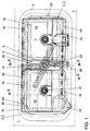
- Fig. 1:
- eine Draufsicht auf ein in der Spritzwand eines Kraftfahrzeuges montiertes Verbindergehäuse von der Motorraumseite aus,
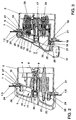
- Fig. 2:
- einen Vertikalschnitt A-A durch das montierte Basisteil des Verbindergehäuses und
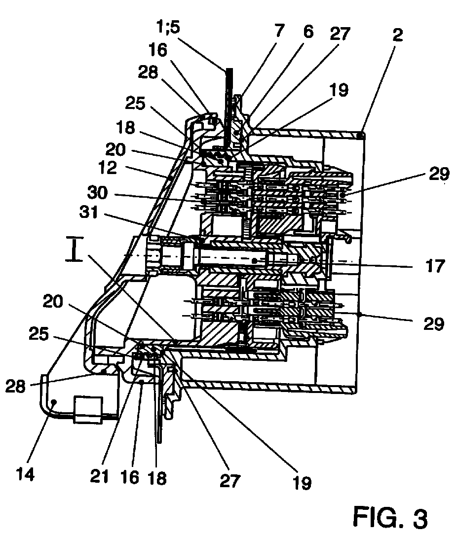
- Fig. 3:
- einen Vertikalschnitt B-B durch den montierten Verbinder.
- Fig. 1:
- 2 shows a plan view of a connector housing mounted in the bulkhead of a motor vehicle from the engine compartment side,
- Fig. 2:
- a vertical section AA through the assembled base part of the connector housing and
- Fig. 3:
- a vertical section BB through the assembled connector.
Fig. 1 zeigt in einer Draufsicht von der Motorraumseite aus ein an der Spritzwand 1
eines Kraftfahrzeuges montiertes erfindungsgemäßes Verbindergehäuse, das aus
einem gestrichelt angedeuteten, hinter der Spritzwand 1 fahrzeuginnenraumseitig
angeordneten Basisteil 2 und einem mit diesem lösbar verbundenen zweiteiligen
Steckermodulträger 3 gebildet ist. Das Verbindergehäuse ist feuchtigkeits- und
schalldicht an dem eine Ausnehmung (4) umschließenden Randbereich 5 der
Spritzwand 1 festgelegt. Das Basisteil 2 weist zwei nebeneinander angeordnete
Öffnungen zur Aufnahme der beiden Teile I und II des Steckermodulträges 3 auf, die
durch einen Steg S voneinander getrennt sind. In diesem Steg S ist feuchtraumseitig
eine Gewindehülse 8 (Fig. 2) für eine Befestigungsschraube 9 mit einem
Innensechskant 9a ausgebildet. An dieser Gewindehülse 8 ist ein T-förmiger Griff 10
angeordnet und mit der Befestigungsschraube 9 drehbar gehaltert und am Basisteil 2
feststellbar. Der Schaft 11 des Griffes 10 umschließt die Gewindehülse 8. Der Griff 10 ist
einerseits Handhabungselement für das Basisteil 2 und zugleich Klemmelement, mit
dem das Basisteil 2 an der Spritzwand 1 festklemmbar ist. Fig. 2 zeigt den Griff 10 im
Schnitt in der Klemmstellung. Es ist zu erkennen, daß die freien Enden des Griffes 10
zum Basisteil 2 gerichtet sind und am Randbereich der Spritzwand 1 anliegen. Diese
Stellung ist in Fig. 1 mit durchgezogenen Linien dargestellt. Die gestrichelt dargestellte
und gegenüber der Klemmstellung verdrehte Position des Griffes 10 entspricht einer
Montierungsstellung beim Einführen des Basisteils 2. Fig. 2 zeigt weiter, daß das
Basisteil 2 mit einer Feuchtigkeitsdichtung 6, versehen ist, die aus Silikon besteht und
fahrzeuginnenraumseitig (trockenraumseitig) an dem Randbereich 5 anliegt, und daß
der Dichtung 6 eine weitere Dichtung 7, die aus einem elastischen Schaumstoff besteht
und als Schalldichtung wirkt, nachgeordnet ist, d.h. bei der gegebenen
Dichtungssituation auf der dem Feuchtraum abgewandten Seite der Dichtung 6 und
damit an deren äußerem Umfang angeordnet ist. Die beiden Teile I und II des
Steckermodulträgers 3 sind mit Abdeckungen 12 und 13 mit jeweils einem
Leitungseinführungskanal 14 bzw. 15 versehen und liegen motorraumseitig
(feuchtraumseitig) mit Anlageelementen 16 an dem Randbereich 5 an und sind jeweils
mit einer zentral angeordneten Befestigungsschraube 17 (Fig. 1, Fig. 3) mit dem
einstückigen Basisteil 2 verschraubbar.1 shows a top view from the engine compartment side on the
Fig. 3 zeigt, daß zwischen dem Teil I und dem Basisteil 2 umfangsseitig (radiale
Richtung) jeweils ein Dichtungsring 18 (Fig. 2, Fig. 3) angeordnet ist (analog zwischen
dem Teil II und dem Basisteil 2, nicht dargestellt), der in axialer Richtung an einer am
Basisteil 2 ausgebildeten Schulter 19 und einer am Teil I (analog am Teil II)
ausgebildeten Schulter 20 zur Anlage gebracht ist. Der Dichtring 18 ist als
Lippendichtung ausgebildet und am Teil I fixiert, wobei die Lippen 21 in radialer Richtung
zum Basisteil weisen.Fig. 3 shows that between the part I and the
Zwischen den beiden Teilen I und II ist im Bereich des Steges S am Basisteil 2 ein Kanal
22 für eine Flüssigkeitsdurchführung angeordnet, der in einem Rohrstück 23 mit
beidseits als Anschlußstutzen für eine Flüssigkeitsleitung gestalteten Enden ausgebildet
ist. There is a channel between the two parts I and II in the area of the web S on the
Die Fig. 2 und 3 zeigen weiterhin, daß der die Ausnehmung 4 umgebende Randbereich
5 der Spritzwand 1 nach der Motorraumseite hin gebördelt ist. An dieser Bördelung 24
liegt das Basisteil 2 mit einem Vorsprung 25 an, der im Anordnungsbereich der Teile I
und II zugleich als Anlage für den Dichtring dient. Im Bereich des Steges S (Fig. 2) sind
an diesem Vorsprung 25 elastische Rastnasen 26 ausgebildet, die die Bördelung 24
hintergreifen. Der Griff 10 befindet sich in der Klemmstellung und liegt mit seinen freien
Enden am Randbereich 5 des Spritzwand 1 fest an, wodurch die Rastnasen einen
Abstand von der Bördelung 24 haben. Die in einer am Basisteil 2 ausgebildeten
umlaufenden Nut 27 angeordnete und als Lippendichtung ausgebildete
Feuchtigkeitsdichtung 6 ist infolge der durch das Anziehen der Befestigungsschraube 9
gegebenen axialen Beaufschlagung des Basisteils 2 in Richtung auf den Randbereich 5
sowohl axial als auch radial beaufschlagt und füllt diese Nut 27 elastisch
zusammengedrückt vollständig aus, wodurch eine zuverlässige Feuchtigkeitsabdichtung
zwischen dem Basisteil 2 und der Spritzwand 1 gegeben ist. Die Dichtung 7 ist ebenfalls
axial beaufschlagt und liegt sowohl am Basisteil als auch an der Spritzwand 1 fest an.2 and 3 also show that the edge area surrounding the
Fig. 3 zeigt einen fertig montierten Verbinder (auch als Trennwandstecker bezeichnet)
mit im Basisteil 2 und im Steckermodulträger 3, Teil I, angeordneten
Steckverbindermodulen. Das Teil I ist mit der Befestigungsschraube 17 am Basisteil 2
festgeschraubt, wobei die Befestigungsschraube 17 ihr steckermodulträgerseitiges
Widerlager an einer am Teil I ausgebildeten Schulter 31 hat (analog Teil II). Die
Anlageelemente 16 des Teils I liegen mit einem durch die Befestigungsschraube 17
erzeugten Druck an der Spritzwand 1 an, wobei die Befestigungsschraube 17 zugleich
das Basisteil 2 fahrzeuginnenraumseitig an die Spritzwand 1 zieht. Überdies liegt die
Abdeckung 12 mit einem Rand 28 auf den Anlageelementen 16 des Teils I auf und preßt
diese motorraumseitig zusätzlich gegen die Spritzwand 1.3 shows a fully assembled connector (also referred to as a partition plug)
with arranged in the
Zur Montage des Verbindergehäuses wird zunächst das Basisteil 2 mit den bereits
eingesetzten Steckermodulen 29 und angelegten Dichtungen 6 und 7 von der
Innenraumseite des Fahrzeugs aus unter Zuhilfenahme des Griffes 10 in die
Ausnehmung 4 eingeführt, wobei der Griff 10 so gestellt ist, daß er ebenfalls die
Ausnehmung 4 passieren kann. Bei dieser Einführung passieren die Rastnasen 26 die
Ausnehmung 4 und hintergreifen die Bördelung 24, und der Vorsprung 25 legt sich an
die Bördelung 24 an. Das Basisteil 2 ist damit in der Aussparung arretiert und
vormontiert. Anschließend wird der Griff 10 so verdreht, daß seine freien Enden am
Randbereich 5 der Spritzwand 1 zur Anlage gelangen. Danach wird die
Befestigungsschraube 9 festgezogen, so daß das Basisteil 2 an die Innenraumseite des
Randbereiches 5 und die freien Enden des Griffes 10 an die Motorraumseite desselben
gepreßt werden. Dabei wird die Dichtung 6 radial und axial beaufschlagt und legt sich
elastisch an die Flächen der Nut 27, den Randbereich 5 und die Innenraumseite der
Bördelung 24 an. Die Dichtung 7 wird in axialer Richtung beaufschlagt. Anschließend
werden die Teile I und II des Steckermodulträgers 3 mit den eingesetzten
Steckermodulen 30 und dem Dichtring 18 auf das Basisteil 2 gesteckt, wobei sich der
Dichtring 18 an die Innenseite des Vorsprungs 25 und die Schulter 19 anlegt. Die
Steckermodule 30 werden mit denen (29) des Basisteils 2 verbunden und in bekannter
Weise verriegelt (nicht dargestellt). Danach werden die Befestigungsschrauben 17
festgezogen, wobei das Basisteil 2 und die Teile I und II aneinandergezogen, d.h. zu
dem bereits festgelegten Basisteil 2 gezogen werden. Dadurch wird der
Steckermodulträger 3 am Basisteil 2 befestigt und zugleich am Spritzblech 1 festgelegt.
Dabei drückt auch der jeweilige Rand 28 der Abdeckungen 12 und 13 auf die
Anlageelemente 16 des jeweiligen Teils I und II und drückt dieses zusätzlich gegen den
Randbereich 5. Das Verbindergehäuse und der gesamte Verbinder (Trennwandstecker)
sind damit fest und zuverlässig feuchtigkeitsdicht und schalldicht an der Spritzwand 1
angeordnet. To assemble the connector housing, the
- 11
- SpritzwandBulkhead
- 22nd
- BasisteilBase part
- 33rd
- SteckermodulträgerConnector module carrier
- 44th
- AusnehmungRecess
- 55
- RandbereichEdge area
- 66
- FeuchtigkeitsdichtungMoisture seal
- 77
- SchalldichtungSoundproofing
- 88th
- GewindehülseThreaded sleeve
- 99
- BefestigungsschraubeFastening screw
- 1010th
- GriffHandle
- 1111
- Schaftshaft
- 1212th
- Abdeckungcover
- 1313
- Abdeckungcover
- 1414
- LeitungseinführungskanalCable entry duct
- 1515
- LeitungseinführungskanalCable entry duct
- 1616
- AnlageelementInvestment element
- 1717th
- BefestigungsschraubeFastening screw
- 1818th
- DichtungsringSealing ring
- 1919th
- Schultershoulder
- 2020th
- Schultershoulder
- 2121
- Lippelip
- 2222
- Kanalchannel
- 2323
- RohrstückPipe piece
- 2424th
- BördelungFlaring
- 2525th
- Vorsprunghead Start
- 2626
- RastnaseLatch
- 2727
- NutGroove
- 2828
- Rand edge
- 2929
- SteckermodulConnector module
- 3030th
- SteckermodulConnector module
Claims (14)
Applications Claiming Priority (2)
| Application Number | Priority Date | Filing Date | Title |
|---|---|---|---|
| DE19811259A DE19811259A1 (en) | 1998-03-14 | 1998-03-14 | Connector housing for arrangement on a partition |
| DE19811259 | 1998-03-14 |
Publications (3)
| Publication Number | Publication Date |
|---|---|
| EP0944136A2 true EP0944136A2 (en) | 1999-09-22 |
| EP0944136A3 EP0944136A3 (en) | 2000-05-10 |
| EP0944136B1 EP0944136B1 (en) | 2002-05-22 |
Family
ID=7860999
Family Applications (1)
| Application Number | Title | Priority Date | Filing Date |
|---|---|---|---|
| EP99103634A Expired - Lifetime EP0944136B1 (en) | 1998-03-14 | 1999-02-25 | Connector housing for mounting in a partition wall |
Country Status (2)
| Country | Link |
|---|---|
| EP (1) | EP0944136B1 (en) |
| DE (2) | DE19811259A1 (en) |
Family Cites Families (8)
| Publication number | Priority date | Publication date | Assignee | Title |
|---|---|---|---|---|
| US4684190A (en) * | 1986-03-05 | 1987-08-04 | General Motors Corporation | Sealed electrical connector with shroud |
| DE9111118U1 (en) * | 1991-09-07 | 1991-10-17 | Hella KG Hueck & Co, 4780 Lippstadt | Control unit for motor vehicles |
| DE4206414C1 (en) * | 1992-02-29 | 1993-08-26 | Mercedes-Benz Aktiengesellschaft, 7000 Stuttgart, De | Watertight plug connector for road vehicle panel - has metal plug that securely latches into elastomer bush that fits into panel aperture |
| FR2698731B1 (en) * | 1992-12-02 | 1995-02-03 | Cinch Connecteurs Sa | Electrical connector. |
| US5328388A (en) * | 1993-05-28 | 1994-07-12 | Yazaki Corporation | Modular electrical connector |
| JP2574806Y2 (en) * | 1993-11-26 | 1998-06-18 | 住友電装株式会社 | connector |
| GB9412242D0 (en) * | 1994-06-18 | 1994-08-10 | Amp Italia | Connector housing fixable to a bulkhead |
| DE29615386U1 (en) * | 1996-09-04 | 1996-11-14 | HTS-Elektrotechnik GmbH, 53819 Neunkirchen-Seelscheid | Open space connector housing |
-
1998
- 1998-03-14 DE DE19811259A patent/DE19811259A1/en not_active Withdrawn
-
1999
- 1999-02-25 DE DE59901483T patent/DE59901483D1/en not_active Expired - Lifetime
- 1999-02-25 EP EP99103634A patent/EP0944136B1/en not_active Expired - Lifetime
Also Published As
| Publication number | Publication date |
|---|---|
| EP0944136A3 (en) | 2000-05-10 |
| DE19811259A1 (en) | 1999-09-16 |
| EP0944136B1 (en) | 2002-05-22 |
| DE59901483D1 (en) | 2002-06-27 |
Similar Documents
| Publication | Publication Date | Title |
|---|---|---|
| EP2147813B1 (en) | Assembly of a fixed window to a bodywork flange and attachment clip for mounting the fixed window | |
| DE3706975C2 (en) | ||
| EP1114256B1 (en) | Rotary quick-acting closure for interconnecting a plurality of structural parts | |
| DE102011010290B4 (en) | Antenna housing, in particular with holder | |
| WO2016177364A1 (en) | Arrangement comprising a wall lead-through for a plurality of cables, method for the production thereof and kit | |
| AT519366B1 (en) | CONNECTION HOUSING AND CONNECTION SYSTEM | |
| EP1511368A2 (en) | Sandwich housing for antenna amplifier | |
| EP1326757A1 (en) | Door module support | |
| DE102005044618A1 (en) | Attachment of a roof antenna of a vehicle with a clamping part | |
| WO2024179774A1 (en) | Housing assembly | |
| EP1429415A2 (en) | Antenna with injection moulded seal | |
| DE102017118478B4 (en) | Locking of a roof antenna of a vehicle using a turnstile | |
| DE102012202677B4 (en) | Roof antenna and method for mounting a roof antenna on a vehicle body of a vehicle | |
| EP0944136B1 (en) | Connector housing for mounting in a partition wall | |
| DE19735731A1 (en) | Motor vehicle headlamp designed for external installation | |
| DE19745384A1 (en) | Electrical jack-plug connector for electrical lines | |
| DE9306316U1 (en) | Washing device for a lens of a lamp or headlight | |
| EP1318928B1 (en) | Cable bushing on a vehicle door | |
| DE19961388B4 (en) | Housing of an electronic module | |
| EP1035989A1 (en) | Device for receiving and locating a battery | |
| DE102012012387A1 (en) | Mounting arrangement for fixing tail lamp at body panel of motor car, has sealing gasket arranged between components, and attaching unit and sealing gasket arranged together to form common manageable component during mounting operation | |
| DE102024127398B3 (en) | Cable wall penetration and arrangement as well as assembly methods | |
| DE102011075533A1 (en) | Trough supply module for motor vehicle for mounting on body flange of body section of motor vehicle body, has protection cover provided with pot flange and mounting hole | |
| EP0984120A1 (en) | Connection assembly | |
| DE10040844B4 (en) | Cable bushing part |
Legal Events
| Date | Code | Title | Description |
|---|---|---|---|
| PUAI | Public reference made under article 153(3) epc to a published international application that has entered the european phase |
Free format text: ORIGINAL CODE: 0009012 |
|
| AK | Designated contracting states |
Kind code of ref document: A2 Designated state(s): DE ES FR GB IT SE |
|
| AX | Request for extension of the european patent |
Free format text: AL;LT;LV;MK;RO;SI |
|
| PUAL | Search report despatched |
Free format text: ORIGINAL CODE: 0009013 |
|
| AK | Designated contracting states |
Kind code of ref document: A3 Designated state(s): AT BE CH CY DE DK ES FI FR GB GR IE IT LI LU MC NL PT SE |
|
| AX | Request for extension of the european patent |
Free format text: AL;LT;LV;MK;RO;SI |
|
| 17P | Request for examination filed |
Effective date: 20001110 |
|
| AKX | Designation fees paid |
Free format text: DE ES FR GB IT SE |
|
| GRAG | Despatch of communication of intention to grant |
Free format text: ORIGINAL CODE: EPIDOS AGRA |
|
| 17Q | First examination report despatched |
Effective date: 20010619 |
|
| GRAG | Despatch of communication of intention to grant |
Free format text: ORIGINAL CODE: EPIDOS AGRA |
|
| GRAH | Despatch of communication of intention to grant a patent |
Free format text: ORIGINAL CODE: EPIDOS IGRA |
|
| GRAH | Despatch of communication of intention to grant a patent |
Free format text: ORIGINAL CODE: EPIDOS IGRA |
|
| GRAA | (expected) grant |
Free format text: ORIGINAL CODE: 0009210 |
|
| PG25 | Lapsed in a contracting state [announced via postgrant information from national office to epo] |
Ref country code: IT Free format text: LAPSE BECAUSE OF FAILURE TO SUBMIT A TRANSLATION OF THE DESCRIPTION OR TO PAY THE FEE WITHIN THE PRE;WARNING: LAPSES OF ITALIAN PATENTS WITH EFFECTIVE DATE BEFORE 2007 MAY HAVE OCCURRED AT ANY TIME BEFORE 2007. THE CORRECT EFFECTIVE DATE MAY BE DIFFERENT FROM THE ONE RECORDED.SCRIBED TIME-LIMIT Effective date: 20020522 Ref country code: GB Free format text: LAPSE BECAUSE OF FAILURE TO SUBMIT A TRANSLATION OF THE DESCRIPTION OR TO PAY THE FEE WITHIN THE PRESCRIBED TIME-LIMIT Effective date: 20020522 |
|
| REG | Reference to a national code |
Ref country code: GB Ref legal event code: FG4D Free format text: NOT ENGLISH |
|
| REF | Corresponds to: |
Ref document number: 59901483 Country of ref document: DE Date of ref document: 20020627 |
|
| PG25 | Lapsed in a contracting state [announced via postgrant information from national office to epo] |
Ref country code: SE Free format text: LAPSE BECAUSE OF FAILURE TO SUBMIT A TRANSLATION OF THE DESCRIPTION OR TO PAY THE FEE WITHIN THE PRESCRIBED TIME-LIMIT Effective date: 20020822 |
|
| ET | Fr: translation filed | ||
| GBV | Gb: ep patent (uk) treated as always having been void in accordance with gb section 77(7)/1977 [no translation filed] |
Effective date: 20020522 |
|
| PG25 | Lapsed in a contracting state [announced via postgrant information from national office to epo] |
Ref country code: ES Free format text: LAPSE BECAUSE OF FAILURE TO SUBMIT A TRANSLATION OF THE DESCRIPTION OR TO PAY THE FEE WITHIN THE PRESCRIBED TIME-LIMIT Effective date: 20021128 |
|
| PLBE | No opposition filed within time limit |
Free format text: ORIGINAL CODE: 0009261 |
|
| STAA | Information on the status of an ep patent application or granted ep patent |
Free format text: STATUS: NO OPPOSITION FILED WITHIN TIME LIMIT |
|
| 26N | No opposition filed |
Effective date: 20030225 |
|
| PGFP | Annual fee paid to national office [announced via postgrant information from national office to epo] |
Ref country code: FR Payment date: 20080212 Year of fee payment: 10 |
|
| REG | Reference to a national code |
Ref country code: FR Ref legal event code: ST Effective date: 20091030 |
|
| PG25 | Lapsed in a contracting state [announced via postgrant information from national office to epo] |
Ref country code: FR Free format text: LAPSE BECAUSE OF NON-PAYMENT OF DUE FEES Effective date: 20090302 |
|
| PGFP | Annual fee paid to national office [announced via postgrant information from national office to epo] |
Ref country code: DE Payment date: 20110228 Year of fee payment: 13 |
|
| REG | Reference to a national code |
Ref country code: DE Ref legal event code: R119 Ref document number: 59901483 Country of ref document: DE Effective date: 20120901 |
|
| PG25 | Lapsed in a contracting state [announced via postgrant information from national office to epo] |
Ref country code: DE Free format text: LAPSE BECAUSE OF NON-PAYMENT OF DUE FEES Effective date: 20120901 |