EP0944016B1 - Verbessertes Verfahren zur Identifizierung von Chipkarten - Google Patents
Verbessertes Verfahren zur Identifizierung von Chipkarten Download PDFInfo
- Publication number
- EP0944016B1 EP0944016B1 EP99400631A EP99400631A EP0944016B1 EP 0944016 B1 EP0944016 B1 EP 0944016B1 EP 99400631 A EP99400631 A EP 99400631A EP 99400631 A EP99400631 A EP 99400631A EP 0944016 B1 EP0944016 B1 EP 0944016B1
- Authority
- EP
- European Patent Office
- Prior art keywords
- interrogation
- message
- bits
- card
- cards
- Prior art date
- Legal status (The legal status is an assumption and is not a legal conclusion. Google has not performed a legal analysis and makes no representation as to the accuracy of the status listed.)
- Expired - Lifetime
Links
Images

Classifications
-
- G—PHYSICS
- G06—COMPUTING; CALCULATING OR COUNTING
- G06K—GRAPHICAL DATA READING; PRESENTATION OF DATA; RECORD CARRIERS; HANDLING RECORD CARRIERS
- G06K7/00—Methods or arrangements for sensing record carriers, e.g. for reading patterns
- G06K7/10—Methods or arrangements for sensing record carriers, e.g. for reading patterns by electromagnetic radiation, e.g. optical sensing; by corpuscular radiation
- G06K7/10009—Methods or arrangements for sensing record carriers, e.g. for reading patterns by electromagnetic radiation, e.g. optical sensing; by corpuscular radiation sensing by radiation using wavelengths larger than 0.1 mm, e.g. radio-waves or microwaves
- G06K7/10316—Methods or arrangements for sensing record carriers, e.g. for reading patterns by electromagnetic radiation, e.g. optical sensing; by corpuscular radiation sensing by radiation using wavelengths larger than 0.1 mm, e.g. radio-waves or microwaves using at least one antenna particularly designed for interrogating the wireless record carriers
- G06K7/10346—Methods or arrangements for sensing record carriers, e.g. for reading patterns by electromagnetic radiation, e.g. optical sensing; by corpuscular radiation sensing by radiation using wavelengths larger than 0.1 mm, e.g. radio-waves or microwaves using at least one antenna particularly designed for interrogating the wireless record carriers the antenna being of the far field type, e.g. HF types or dipoles
-
- G—PHYSICS
- G06—COMPUTING; CALCULATING OR COUNTING
- G06K—GRAPHICAL DATA READING; PRESENTATION OF DATA; RECORD CARRIERS; HANDLING RECORD CARRIERS
- G06K7/00—Methods or arrangements for sensing record carriers, e.g. for reading patterns
- G06K7/0008—General problems related to the reading of electronic memory record carriers, independent of its reading method, e.g. power transfer
-
- G—PHYSICS
- G06—COMPUTING; CALCULATING OR COUNTING
- G06K—GRAPHICAL DATA READING; PRESENTATION OF DATA; RECORD CARRIERS; HANDLING RECORD CARRIERS
- G06K7/00—Methods or arrangements for sensing record carriers, e.g. for reading patterns
- G06K7/10—Methods or arrangements for sensing record carriers, e.g. for reading patterns by electromagnetic radiation, e.g. optical sensing; by corpuscular radiation
- G06K7/10009—Methods or arrangements for sensing record carriers, e.g. for reading patterns by electromagnetic radiation, e.g. optical sensing; by corpuscular radiation sensing by radiation using wavelengths larger than 0.1 mm, e.g. radio-waves or microwaves
- G06K7/10316—Methods or arrangements for sensing record carriers, e.g. for reading patterns by electromagnetic radiation, e.g. optical sensing; by corpuscular radiation sensing by radiation using wavelengths larger than 0.1 mm, e.g. radio-waves or microwaves using at least one antenna particularly designed for interrogating the wireless record carriers
- G06K7/10336—Methods or arrangements for sensing record carriers, e.g. for reading patterns by electromagnetic radiation, e.g. optical sensing; by corpuscular radiation sensing by radiation using wavelengths larger than 0.1 mm, e.g. radio-waves or microwaves using at least one antenna particularly designed for interrogating the wireless record carriers the antenna being of the near field type, inductive coil
Definitions
- the present invention relates to an improved method of identifying electronic cards.
- Dialogue is a contactless dialogue.
- the messages are transmitted by radiofrequency or microwave electromagnetic carrier wave.
- the transmission channel is thus constituted by the ambient space.
- an electronic card may in particular be an electronic module, a badge or a smart card, and be worn by an individual, a vehicle, a device, livestock, etc.
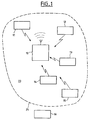
- the unit of interrogation is for example included in a base station, an access control terminal, a toll terminal on the fly, etc.
- the interrogation unit is mobile and the electronic cards are fixed. In another variant, the interrogation unit and the electronic cards are mobile.
- cards such as cards 11 to 15 may be inside a zone 20, centered on the interrogation unit 10, which is the range of the messages exchanged, whereas Other cards such as card 16 may be outside this area.
- the limit of this zone 20 is symbolized by a broken line 25. It will be noted that the limit of the zone 20 may vary over time, for example because of the presence of foreign objects forming a screen for the propagation of electromagnetic waves.
- the volume of air included in the zone 20 constitutes the transmission channel of the messages exchanged between the interrogation unit on the one hand and the electronic cards on the other hand.
- This channel is unique and must be shared in time according to a communication protocol between the unit and the cards.
- This protocol is of the master / slave type. Indeed, each message exchange between the interrogation unit (the master) and a determined card (the slave) is initiated by the interrogation unit.
- the electronic cards are in a state that does not allow them to receive the command messages issued by the interrogation unit, nor, a fortiori, to respond. To qualify this state of electronic cards, they are said to be "dormant”.
- the interrogation unit before issuing a command message to a specific electronic card, the interrogation unit must first "wake up" said card, to place it in a state allowing it to receive the control message and, if necessary, to answer it by sending a response message. For this purpose, the interrogation unit sends a particular message W, called “wake-up message”, to the electronic card concerned. After transmission of the control message and optionally reception of the response message, the interrogation unit sends a particular message S, called “sleep message”, to the card. This then returns to the state in which it can not receive a command message.
- the wake up message W and the sleep message S presented above each include a single parameter which is an identification number of the electronic card for which they are intended. That is why they are written respectively W (X) and S (X), where X is the value of an identification number making it possible to identify the electronic card to which the control message is intended.
- Such an identification number is uniquely assigned to each electronic card.
- a unique identification number is associated with each electronic card.
- the interrogation unit ignores a priori whether electronic cards are within range of the control messages that it issues. If so, she does not know how many cards are present and most importantly, she does not know which cards are present.
- this zone 20 is called the investigation zone, insofar as it is the zone within which the method to which the invention relates is to detect and identify the electronic cards present.
- identifying an electronic card present amounts to identifying its identification number. Indeed, it is the knowledge of the identification numbers of the cards present which makes it possible to ensure the management of the exchanges of control messages.
- the "root" of the tree gives rise to two “branches” each terminating in a "node” corresponding to the logic value respectively 1 or 0 of a first bit of the identification number, for example the most significant bit. These two nodes each give rise to two new branches each terminating in a node corresponding to the logical value 1 or 0 respectively of another bit of the identification number, for example the bit of immediately lower weight. And so on until the last "generation" of the tree knowing that, starting from the root, the tree has as many generations as there are bits to encode the identification numbers.
- each node other than those of the first generation (which correspond to the logical value of the most significant bit) has a father corresponding to the logical value of the higher-order bit
- each node other than a node of the last generation (which corresponds to the value of the least significant bit of the identification number) has two "wires" corresponding to the logical value of the least significant bit.
- Any traversal performed in the tree from the root to a node of the last generation assigns a logical value of 1 or 0 to each bit of the identification number, starting with the most significant bits. in the example.
- the principle of the known methods consists precisely in traversing the tree of FIG. 2 in order to deduce therefrom the identification numbers of the electronic cards present in the investigation zone. More specifically, these methods comprise steps of transmission by the interrogation message interrogation unit to the electronic cards present in the investigation zone or at least to a group of such cards which are allowed to respond, and transmission steps by said response message cards.
- the interpretation of the response messages received by the interrogation unit at each iteration of the algorithm makes it possible to advance in the tree of the identification numbers by identifying the value of an additional bit of the identification number of at least one of said cards.
- each response message issued by a card authorized to respond includes the complete identification number of said card.
- the object of the present invention is to propose a method for identifying electronic cards perfected, which is faster than those known in the state of the art.
- the identification number of a present card is reconstituted not bit by bit but block of bits by block of bits.
- the size of a block is variable and determined by the rank i at which occurs a possible collision between the bits of the variable numbers issued by the cards.
- the identification of the present cards may require fewer iterations than there are bits to identify.
- the transmission of messages by the interrogation unit and by the electronic cards is carried out according to a determined communication protocol which specifies the format and the syntax of the messages.
- the transmission takes place synchronously. It is sequenced at a fixed rate, the interrogation unit and the electronic cards comprising known means to lock on the rhythm of the same clock or two synchronous or diasynchronous clocks.
- the transmitted messages comprise one (or more) useful information word (s) and several service bits.
- the message firstly comprises a start bit START whose function is to synchronize the clock of the destination unit with the received message.
- the message then comprises at least one useful information word such as the word INFO, for example coded on eight bits (one byte).
- This word can be an instruction word, the value of which indicates the nature of a command to be performed by the destination unit. It can also be an address word, the value of which indicates the address or part of the address of a memory location of the destination unit to which, for example, a data item is to be read or written. Finally, it can also be a data word whose value indicates the value of a data to be processed by the unit or the destination card.
- the message further comprises a CHECK control bit which may in particular be a parity check bit.
- the value of the CHECK bit is set to logical value 1 or 0, in order to complete the sum of the values of the bits of the useful information word INFO to an even or odd value according to the type of parity adopted.
- the role of the CHECK control bit is to enable the destination unit to detect possible transmission errors, so as to solicit a re-transmission of the message. Transmission errors can be caused by disturbances on the channel.
- the message finally includes a STOP end of transmission bit, which indicates the end of the message.
- the protocol generally provides for a number of elementary time units following the STOP bit, during which the sending unit no longer emits any bit on the channel, in order to leave it free for the destination unit to transmit a message.
- acknowledgment bit of the logical value communication determined.
- the value of this acknowledgment bit indicates whether the message has been correctly received, in particular as a function of the check performed using the check bit CHECK, and, if necessary, whether a re-transmission of the message is required.
- Figure 2 there is shown four such elementary time units following the aforementioned STOP bit.
- an elementary time unit corresponds to the normal transmission time of a bit. This duration depends on the digital bit rate of the transmission.
- the syntax of the transmitted messages ie the transmission order of the different types of useful information words transmitted (command word, address word or data word) is determined by the communication protocol specific to the system.
- each card is uniquely assigned an identification number encoded on eight bits (one byte).
- the identification number is saved in a memory.
- the identification number is assigned at the factory during the production of the card electronic.
- the memory is then a non-volatile memory, of the type of an EPROM, EEPROM, EPROM-Flash memory, etc. In the following, we will consider that this is the case.
- the identification number is randomly defined and assigned to each card, dynamically, at its first entry into the range 20 surrounding the interrogation unit 10 ( Figure 1).
- the memory can then be a volatile memory of the type of a random access memory (RAM).
- the information is transmitted at a digital rate equal to 106 kilobits per second (Kbps).
- the messages are transmitted by amplitude modulation of a radiofrequency carrier wave of frequency equal to 13.56 Megahertz (MHz). The depth of the modulation is equal to 15%.
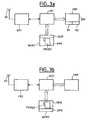
- FIG. 3a there is schematically shown an embodiment of an electronic card suitable for implementing the method according to the invention.
- Such a card comprises an antenna A1 for transmitting and receiving radio frequency electromagnetic messages.
- This antenna A1 is connected to a transmission / reception module ER1, which groups together a set of known means that need not be described in detail in the present description insofar as they are in themselves within the scope of the present invention. skilled person.
- these means are intended to fulfill several functions.
- reception they make it possible to filter the radio frequency signal picked up by the antenna A1, to demodulate it, to filter the demodulated signal to eliminate the components at low frequencies due to the electromagnetic noise introduced by the transmission channel, to find the frequency and the rate of transmission, to sample the demodulated signal of synchronously, and finally to extract the useful data from the received message.
- transmission they make it possible to format a message to be transmitted from the word (s) of useful information to be transmitted, to generate the radiofrequency carrier at 13.56 MHz, to modulate it in amplitude as a function of the value of the bits of the message to be transmitted, to amplify the modulated radiofrequency signal and to apply it to the input of the antenna A1.
- the card further comprises a UC1 control unit intended to control its operation. It can be a microprocessor.
- the control unit UC1 is linked to a non-volatile memory NVM1.
- This memory includes a zone PM1 in which a program PROG1 of operation of the card, which controls the control unit UC1, is permanently recorded. It also includes an IDN1 zone in which the card identification number is permanently registered.
- the control unit UC1 is also connected to a volatile memory VM1.
- This memory includes a zone DM1 in which data can be saved during operation of the card. It will be seen below that the variable number according to the invention is saved in this zone DM1 during the implementation of the identification method according to the invention.
- This memory further includes memory locations such as registers R1 and R2 suitable for saving two digital information (or flags) whose logical value 1 or 0 determines configurations of the card.
- the registers R1 and R2 have the function of indicating, for the first, if the card has already been identified in which case it is not allowed to answer an interrogation message sent by the interrogation unit, and for the latter, if it is authorized to answer the particular interrogation messages sent by the interrogation unit.
- the general interrogation message and the particular interrogation messages cited above are messages involved in the implementation of the identification method according to the invention, the role of which will be explained later.
- the state register R1 is tested on receipt of any general interrogation message. If this register is in logical 0, no action occurs in the card. In particular, the card emits no response message. Similarly, the register R2 is tested upon receipt of any particular query message. If this register is in logical 0, no action occurs in the card. In particular, the card emits no response message.
- the registers R1 and R2 are initially programmed at logic value 1 so that the card is authorized to answer, respectively, a general interrogation message and a particular interrogation message.
- the emission of the signal of dormancy of a card which has just been identified causes the programming a logic value 0 in the status registers R1 and R2 of the card, so that said card is no longer authorized to respond to general or particular polling messages later issued by the interrogation unit.
- FIG. 3b there is shown a schematic embodiment of an interrogation unit suitable for implementing the method according to the invention.
- the interrogation unit comprises an antenna A2, a transmission / reception module ER2, a control unit UC2 and a non-volatile memory NVM2. comprising a program area PM2 and a data area DM2.
- the PM2 program zone has the function of permanently saving a PROG2 program controlling the UC2 control unit for the implementation of the identification method according to the invention.
- the DM2 data area contains data of a different nature than a card identification number. This data may include an identification number of the interrogation unit, a number and / or manufacturing references, etc.
- the control unit UC2 of the interrogation unit is also connected to a volatile memory VM2 comprising a first zone in which is memorized a number being reconstituted (hereinafter number RN), a second zone in which is stored a modulo eight counter whose value will be noted k 'in the following, and a third area in which are recorded the identification numbers of the present cards already identified.
- a volatile memory VM2 comprising a first zone in which is memorized a number being reconstituted (hereinafter number RN), a second zone in which is stored a modulo eight counter whose value will be noted k 'in the following, and a third area in which are recorded the identification numbers of the present cards already identified.
- the identification method according to the invention consists in identifying the cards present in the investigation zone 20 by reconstituting their identification numbers, according to a tree-based iterative algorithm.
- the invention allows a faster identification of the cards present in the area of investigation insofar as an identification number can be reconstituted block of bits per block of bits.
- the size of a block of bits identified at a given iteration of the algorithm depends, as will become clearer below, on the value of the identification number of the other unidentified and answerable cards that are also located. in the investigation area.
- the identification numbers are identified starting with their bit (s) of highest weight, then the other bits in descending order of their weight.
- the most significant bit of an identification number will sometimes be designated by reference to the "first" bit of said number.
- Each iteration of the algorithm of the method according to the invention comprises, in particular, a step A of sending an interrogation message by the interrogation unit, and if necessary, a step B of transmission of a message. response message by at least one card still unidentified, and a step C of receiving and analyzing response messages received by the interrogation unit.
- the interrogation message sent by the interrogation unit can be of two different types. It may be a general polling message GC, but it may also be a particular polling message PC.
- a general interrogation message is a message having the format shown in FIG. 2 in which the useful information word transmitted is a command word whose value is for example 00100000.
- a particular interrogation message is a message having the format shown in FIG. 2 in which the useful information word transmitted is a command word whose value is for example 00101xxx.
- the three least significant bits of this word determine the value of a parameter k of the message, which can take 8 different values (for 8-bit coded identification numbers). This is why, in the following, the reference PC (k) is used to designate a particular interrogation message whose parameter is equal to k. The role of this parameter will appear in the following.
- a general interrogation message is issued at the first iteration of the algorithm according to the invention.
- a general GC poll message is sent to all cards in the investigation area that are still unidentified.
- the meaning of the term "destination" used above must be specified: this expression introduces the group of cards on which the message in question produces an effect, ie the cards that receive it and in which action is performed as a result of this reception. For other cards that may be present, the message has no effect, ie no action is performed.
- step C The possible reception and, if necessary, the analysis of these response messages, by the interrogation unit (step C), makes it possible to define whether an action must be performed or not during another iteration and, if so, what action should be taken. Indeed, three cases can occur.
- a first case is one in which at least two reply messages are received, these messages necessarily being received simultaneously insofar as the cards respond within the same time interval after receiving the interrogation message. It will be noted that, by hypothesis, the bits of the variable numbers transmitted in the response messages are transmitted starting with the most significant bits.
- a second case is where a single response message is received. This means that there is only one unidentified map in the investigation area. He then has no collision in the bits of the variable number received. This therefore unambiguously indicates the value of the unidentified bits of the number NR.
- a third case is finally where no response message is received by the interrogation unit. This means that there are no unidentified electronic cards in the investigation area.
- the response messages transmitted by the electronic card (s) concerned are received and analyzed by the interrogation unit in a step C which proceeds in the same manner as described. above regarding the processing of a beginning iteration by issuing a general polling message. There is therefore no need to revisit this description.
- a portion of the still unidentified cards may be placed in a state in which it is no longer allowed to respond to the particular interrogation messages (due to programming a logic value 0 in their second state register R2).
- progress is made in the tree of the identification numbers since one or more bits are identified, that is to say that we descend from one or more generations of the tree.
- the function of the state registers R1 and R2 is to indicate for each card respectively whether it has already been identified and whether it is authorized to respond to the particular interrogation messages. Nevertheless, those skilled in the art can consider other ways of ensuring the function of these two registers. The same remark can be made regarding the modulo eight counter giving the value of k '. This is why the registers R1 and R2 and the number k ', as well as the operations concerning them, have been presented above only to illustrate a possible example for the implementation of the algorithm of the method according to the invention. invention.
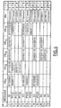
- Figure 4 is a table in which the first column (left) indicates the number of an iteration of the algorithm.
- the second column indicates, for each iteration, the nature of the interrogation message that is issued by the interrogation unit, specifying, for the particular interrogation messages, the value of the parameter k in parentheses.
- the value of the rank i which possibly occurs a collision between the bits of the variable numbers sent in response to the interrogation messages.
- the value of i is zero.
- the content of the table speaks for itself, and this includes very well given the details given above concerning the progress of each iteration in the general case. Also it does not appear necessary to comment on the content of each row of the table.
- step 12 no card issues a response message (there is no variable number in any column VN 11 to VN 15 ), which indicates that there is no longer unidentified map in the investigation area.
- This very good result is enabled by the advantageous effect of the method of the invention according to which a block of several bits can be identified at each iteration. For example, we see that at the ninth iteration, we managed to identify six bits of the identification number of a present card (the card 11).
- the coding of the bits is done according to a coding with return to zero of the signal in the length of the bit (so-called "RZ" codings), like a MANCHESTER type coding.
- the transmission of a logical value bit 1 corresponds to an electrical signal on the transmission channel which is at a high level (for example 5 volts) during the first half of the bit transmission duration To (To corresponds to an elementary time unit), and which is at a low level (for example 0 volts) during the second half of this duration To.
- FIGS. 5a to 5d show the level of the electrical signal present on the transmission channel in different cases.
- FIG. 5b corresponds to the case where a bit of logic value 0 is transmitted alone and in the case where several bits of logic value 0 are transmitted simultaneously. These two cases call the same remark as in the preceding paragraph.
- FIG. 5c corresponds to the case where at least one logical value bit 1 and at least one logical value bit 0 are transmitted simultaneously. Note that, since the electrical signals are complementary to one another, the resultant of their superposition is an electrical signal at the high level (5 volts) for the duration duration T. This is the case of a collision between bits transmitted on the channel.
- Figure 5d corresponds to the case where no bit is transmitted on the transmission channel. It is obvious that no electrical signal is then present on said channel.
- the sampling means of the interrogation unit must take a sample in the first half of the duration To and a second sample in the second half of this duration. These two samples can have either a high and a low level, a low level and a high level, or two high levels, or two low levels. Then we are respectively in the case of Figures 5a, 5b, 5c, and 5d. That is, a bit of logic value 1, a logical value bit 0, a collision, or a bit absence are respectively present.
Claims (9)
- Verfahren zur Identifizierung von elektronischen Karten (11-15), denen jede auf eindeutige Art und Weise eine Identifizierungsnummer zugeordnet ist, wobei das Verfahren darin besteht, die Identifizierungsnummern von Karten, die in einem Ermittlungsbereich (20) vorhanden sind, gemäß einem iterativen, verzweigten Algorithmus wieder herzustellen, dadurch gekennzeichnet, dass der Algorithmus bei jeder Iteration die nachfolgenden Schritte aufweist:A) Aussenden einer Abfragenachricht durch eine Abfrageeinheit (10), wobei die Abfragenachricht aufweist:- entweder eine allgemeine Abfragenachricht (GC) mit dem Ziel aller vorhandener, noch nicht identifizierter Karten, die sich in dem Ermittlungsbereich befinden können, wobei eine derartige allgemeine Abfragenachricht insbesondere bei der ersten Iteration des Verfahrens ausgesendet wird;- oder eine spezielle Abfragenachricht (PC(k)) mit dem Ziel von nur gewissen der Karten, die dazu bevollmächtigt sind, auf eine derartige Nachricht zu antworten;B) Aussenden einer Antwortnachricht, welche gleichzeitig die variable Nummer (VNP) aufweist durch:- entweder, wenn die Abfragenachricht eine allgemeine Abfragenachricht (GC) ist, jede der vorhandenen, noch nicht identifizierten Karten, in welchem Fall der Wert der Identifizierungsnummer der Karte vor dem Aussenden als laufender Wert der variablen Nummer angenommen wird;- oder, wenn die Abfragenachricht eine spezielle Abfragenachricht ist, lediglich diejenigen vorhandenen Karten, welche zum Antworten auf eine derartige Nachricht bevollmächtigt sind, die eine variable Nummer (VNp) aufweisen, deren k-tes Bit einen vorherbestimmten logischen Wert aufweist, in welchem Fall der laufende Wert der variablen Nummer (VNP) vor dem Aussenden durch eine Verschiebung seiner Bits um eine Anzahl von Stellen gleich zu k verändert wird, wobei k ein ganzzahliger Parameter der speziellen Abfragenachricht ist, wobei die anderen Karten sich in einen Zustand setzen, in welchem sie nicht mehr bevollmächtigt sind, auf die speziellen Abfragenachrichten zu antworten, und in welchem sie nur bei Empfang einer neuen allgemeinen Abfragenachricht (GC) herausgehen;C) gleichzeitiges Empfangen von Antwortnachrichten durch die Abfrageeinheit und Analysieren der empfangenen Nummern für,C1) im Fall eines Empfangs von mindestens zwei Antwortnachrichten, wobei somit eine durch den gleichzeitigen Empfang von zwei Bits von unterschiedlichen Werten definierte Kollision notwendigerweise um eine Stelle i der gleichzeitig empfangenen variablen Nummern (VNp) eintritt, die Identifizierung des Werts einer Gruppe von i Bits der Nummer einer vorhandenen, noch nicht identifizierten Karte und unter Zurückkehren zu Schritt A), das Aussenden einer speziellen Abfragenachricht, deren Parameter k vom Wert i angenommen wird; oderC2) im Fall eines Empfangs einer einzigen Antwortnachricht die Identifizierung einer Gruppe der j letzten noch nicht identifizierten Bits der Identifizierungsnummer einer vorhandenen Karte derart, dass die Karte identifiziert wird und unter Zurückkehren zu Schritt A), das Aussenden einer allgemeinen Abfragenachricht (GC).
- Verfahren nach Anspruch 1, dadurch gekennzeichnet, dass es zwischen dem Schritt C2) und dem Schritt A) einen Schritt des Aussendens einer Stilllegenachricht durch die Abfrageeinheit mit dem Ziel der so identifizierten Karte derart aufweist, dass die Karte nicht mehr bevollmächtigt ist, auf allgemeine oder spezielle Abfragenachrichten, die durch die Abfrageeinheit ausgesendet werden, zu antworten.
- Verfahren nach Anspruch 1, dadurch gekennzeichnet, dass in Schritt C1) die i identifizierten Bits für die i-1 ersten unter ihnen von dem Wert der i-1 Bits der variablen, vor der Kollision empfangenen Nummern, angenommen werden und den i-ten unter ihnen ein vorherbestimmter logischer Wert, gleich zu demjenigen, der in Schritt B) in Betracht gezogen wird.
- Verfahren nach Anspruch 1, dadurch gekennzeichnet, dass in Schritt C2) die j identifizierten Bits durch den Wert der ersten j Bits der variablen Nummer angenommen werden, die in der Antwortnachricht aufgenommen wird, derart, dass die Identifizierungsnummer einer vorhandenen Karte vollständig wieder hergestellt wird.
- Verfahren nach einem der vorangegangenen Ansprüche, dadurch gekennzeichnet, dass wenn die Bits der variablen Nummern durch die Abfrageeinheit unter Beginn mit den stark ins Gewicht fallenden Bits empfangen werden, die Verschiebung der Bits der variablen Nummer, die um i Stellen in Schritt B) ausgeführt wird, eine Verschiebung nach links ist.
- Verfahren nach Anspruch 5, dadurch gekennzeichnet, dass in der Maßgabe, dass die Bits der variablen Nummer nach links verschoben werden, die i Bits von geringem Gewicht der Nummer einen gleichen logischen, vorherbestimmten von Wert 1 oder 0 annehmen, zum Beispiel den logischen Wert 1.
- Karte, dadurch gekennzeichnet, dass sie angepasst ist, im Rahmen des Verfahrens nach einem der Ansprüche 1 bis 6 umgesetzt zu werden und dass sie aufweist:- eine Steuerungseinheit (UC1), die durch ein Programm (PROG1) gesteuert wird, welches den Schritt B des Verfahrens umsetzt;- einen Bereich (PM1) eines nicht-flüchtigen Speichers (NVM1) zum Sichern des Programms;- einen Bereich (IDN1) eines nicht-flüchtigen Speichers (NMV1) zum Speichern seiner Identifizierungsnummer;- ein erstes Zustandsregister (R1), das in einem vorherbestimmten logischen Wert ist, zum Beispiel dem logischen Wert 0, wenn die Karte schon identifiziert worden ist, und in dem komplementären logischen Wert im entgegen gesetzten Fall;- ein zweites Zustandsregister (R2), das in einem vorherbestimmten logischen Wert ist, zum Beispiel dem logischen Wert 1, wenn die Karte bevollmächtigt ist, auf spezielle Abfragenachrichten zu antworten, die von der Abfrageeinheit (10) ausgesendet werden;- einen Bereich eines flüchtigen Speichers (VM1) zum Speichern der variablen Nummer (VNP);- Mittel (ER1) zum Aussenden/Empfangen von Nachrichten.
- Abfrageeinheit dadurch gekennzeichnet, dass sie angepasst ist, im Rahmen des Verfahrens nach einem der Ansprüche 1 bis 6 umgesetzt zu werden, und dass sie aufweist:- eine Steuerungseinheit (UC2), die durch ein Programm (PROG2) gesteuert wird, das die Schritte A und C des Verfahrens umsetzt;- einen Bereich (PM2) eines nicht-flüchtigen Speichers (NVM2) zum Sichern des Programms;- einen Bereich eines flüchtigen Speichers (VM2) zum Speichern der Identifizierungsnummern von schon identifizierten Karten;- einen Bereich eines flüchtigen Speichers (VM2) zum Speichern einer Nummer (RN), welche gerade wieder hergestellt wird;- Mittel (ER2) zum Aussenden/Empfangen von Nachrichten.
- System zur Identifizierung, das zum Umsetzen des Verfahrens nach einem der Ansprüche 1 bis 6 angepasst ist, dadurch gekennzeichnet, dass es mehrere elektronische Karten (11-15) nach Anspruch 7 und eine Abfrageeinheit (10) für Karten nach Anspruch 8 aufweist.
Applications Claiming Priority (2)
| Application Number | Priority Date | Filing Date | Title |
|---|---|---|---|
| FR9803183A FR2776097B1 (fr) | 1998-03-16 | 1998-03-16 | Procede perfectionne d'identification de cartes electroniques |
| FR9803183 | 1998-03-16 |
Publications (2)
| Publication Number | Publication Date |
|---|---|
| EP0944016A1 EP0944016A1 (de) | 1999-09-22 |
| EP0944016B1 true EP0944016B1 (de) | 2006-02-08 |
Family
ID=9524077
Family Applications (1)
| Application Number | Title | Priority Date | Filing Date |
|---|---|---|---|
| EP99400631A Expired - Lifetime EP0944016B1 (de) | 1998-03-16 | 1999-03-15 | Verbessertes Verfahren zur Identifizierung von Chipkarten |
Country Status (4)
| Country | Link |
|---|---|
| US (1) | US6321982B1 (de) |
| EP (1) | EP0944016B1 (de) |
| DE (1) | DE69929764T2 (de) |
| FR (1) | FR2776097B1 (de) |
Families Citing this family (15)
| Publication number | Priority date | Publication date | Assignee | Title |
|---|---|---|---|---|
| US6607136B1 (en) * | 1998-09-16 | 2003-08-19 | Beepcard Inc. | Physical presence digital authentication system |
| WO2001041043A1 (en) * | 1999-12-03 | 2001-06-07 | Gemplus Tag (Australia) Pty Ltd | Electronic label reading system |
| US7253717B2 (en) * | 2000-11-29 | 2007-08-07 | Mobile Technics Llc | Method and system for communicating with and tracking RFID transponders |
| US6988667B2 (en) | 2001-05-31 | 2006-01-24 | Alien Technology Corporation | Methods and apparatuses to identify devices |
| US7193504B2 (en) * | 2001-10-09 | 2007-03-20 | Alien Technology Corporation | Methods and apparatuses for identification |
| DE10151119C2 (de) * | 2001-10-15 | 2003-11-20 | Siemens Ag | Verfahren zum Erfassen von mehreren Feldgeräten in einer Gerätekonfiguration |
| DE10336308A1 (de) * | 2003-08-01 | 2005-03-03 | Atmel Germany Gmbh | Verfahren zur Auswahl eines oder mehrerer Transponder |
| US8102244B2 (en) | 2003-08-09 | 2012-01-24 | Alien Technology Corporation | Methods and apparatuses to identify devices |
| DE10349647B4 (de) * | 2003-10-21 | 2006-08-10 | Atmel Germany Gmbh | Verfahren zur Auswahl eines oder mehrerer Transponder |
| US7716160B2 (en) | 2003-11-07 | 2010-05-11 | Alien Technology Corporation | Methods and apparatuses to identify devices |
| JP4861002B2 (ja) | 2005-01-03 | 2012-01-25 | 三星電子株式会社 | 固有識別子を利用した通信衝突防止プロトコル |
| KR101059872B1 (ko) * | 2005-01-03 | 2011-08-29 | 삼성전자주식회사 | 고유 식별자를 이용한 통신충돌방지 프로토콜 |
| US20070001812A1 (en) * | 2005-06-30 | 2007-01-04 | Symbol Technologies, Inc. | Systems and methods for optimizing communications between an RFID reader and a tag population using partial binary tree traversal |
| FR2968804B1 (fr) | 2010-12-13 | 2013-01-04 | St Microelectronics Rousset | Procede de gestion du dialogue entre un equipement et au moins un objet multi-applicatif tel qu'une carte a puce sans contact et objet correspondant |
| FR3029661B1 (fr) * | 2014-12-04 | 2016-12-09 | Stmicroelectronics Rousset | Procedes de transmission et de reception d'un signal binaire sur un lien serie, en particulier pour la detection de la vitesse de transmission, et dispositifs correspondants |
Family Cites Families (11)
| Publication number | Priority date | Publication date | Assignee | Title |
|---|---|---|---|---|
| US4071908A (en) * | 1977-03-17 | 1978-01-31 | Bell Telephone Laboratories, Incorporated | Adaptive polling technique |
| DE3851168T2 (de) * | 1987-03-31 | 1995-03-30 | Identec Ltd | Zugangskontrolleinrichtung. |
| US5216419A (en) * | 1987-12-17 | 1993-06-01 | Omron Tateisi Electronics Co. | Data carrier identification system |
| NL8802718A (nl) * | 1988-11-04 | 1990-06-01 | Nedap Nv | Het achtereenvolgens uitlezen van meerdere radiofrequente detectielabels in een ondervraagveld. |
| US5266925A (en) * | 1991-09-30 | 1993-11-30 | Westinghouse Electric Corp. | Electronic identification tag interrogation method |
| US5602538A (en) * | 1994-07-27 | 1997-02-11 | Texas Instruments Incorporated | Apparatus and method for identifying multiple transponders |
| US5489908A (en) * | 1994-07-27 | 1996-02-06 | Texas Instruments Deutschland Gmbh | Apparatus and method for identifying multiple transponders |
| US5550547A (en) * | 1994-09-12 | 1996-08-27 | International Business Machines Corporation | Multiple item radio frequency tag identification protocol |
| US5856788A (en) * | 1996-03-12 | 1999-01-05 | Single Chips Systems Corp. | Method and apparatus for radiofrequency identification tags |
| US5929801A (en) * | 1997-07-11 | 1999-07-27 | Texas Instruments Incorporated | Method for repeating interrogations until failing to receive unintelligible responses to identify plurality of transponders by an interrogator |
| US6072801A (en) * | 1998-02-19 | 2000-06-06 | Micron Technology, Inc. | Method of addressing messages, method of establishing wireless communications, and communications system |
-
1998
- 1998-03-16 FR FR9803183A patent/FR2776097B1/fr not_active Expired - Fee Related
-
1999
- 1999-03-15 DE DE69929764T patent/DE69929764T2/de not_active Expired - Fee Related
- 1999-03-15 EP EP99400631A patent/EP0944016B1/de not_active Expired - Lifetime
- 1999-03-16 US US09/268,970 patent/US6321982B1/en not_active Expired - Lifetime
Also Published As
| Publication number | Publication date |
|---|---|
| EP0944016A1 (de) | 1999-09-22 |
| US6321982B1 (en) | 2001-11-27 |
| FR2776097A1 (fr) | 1999-09-17 |
| DE69929764D1 (de) | 2006-04-20 |
| DE69929764T2 (de) | 2006-11-02 |
| FR2776097B1 (fr) | 2000-08-11 |
Similar Documents
| Publication | Publication Date | Title |
|---|---|---|
| EP0944016B1 (de) | Verbessertes Verfahren zur Identifizierung von Chipkarten | |
| CA2191787C (fr) | Procede d'interrogation a distance d'etiquettes, station et etiquette pour sa mise en oeuvre | |
| EP0935222B1 (de) | Verfahren zum Identifizieren von in einem Untersuchungsbereich präsentierten elektronischen Karten | |
| EP0495708B1 (de) | Kommunikationsanlage zwischen einer ortsgebundenen Station und mobilen Stationen | |
| EP0942386B1 (de) | Verfahren und System zum mehrmaligen Lesen einer Sammlung von Etiketten mit verschiedenen Identifikationskodes | |
| EP0472472B1 (de) | Vorrichtung zum Ferngespräch zwischen einer Station und einem oder mehreren tragbaren Gegenständen | |
| WO1998039725A1 (fr) | Procede de gestion des collisions dans un systeme d'echange de donnees sans contact | |
| EP0897563A1 (de) | Verfahren zur auswahl eines elektronischen moduls aus mehreren im abfragefeld eines endgeräts | |
| EP1257964B1 (de) | Verfahren zum lesen von elektronischen etiketten mittels gleichzeitiger identifizierung ihres kodes | |
| EP1600880B1 (de) | Verfahren zum Lesen eines Speichers in einem kontaktlosen Datenträger | |
| EP0779590A1 (de) | Verfahren zur Verwaltung gleichzeitiger Zugriffe und Gerät zur Durchführung dieses Verfahrens | |
| EP0997835B1 (de) | Verfahren zur Identifizierung von Chipkarten | |
| EP0512882B1 (de) | Erkennungsverfahren und Steuerungsanordnung einer zu einem Empfänger gesendeten digitalen Nachrichtenform | |
| EP0957442A1 (de) | Elektronisches Identifizierungssystem für mehrere Transponder | |
| EP0942387B1 (de) | Verfahren und System zum mehrmals Lesen einer dynamischen Sammlung von Etiketten | |
| EP0932271B1 (de) | Kommunikationsverfahren mit verbesserter Empfangsquittierung | |
| EP1330781A1 (de) | Schaltung zur detektion und umsetzung einer datenspur | |
| EP0191999B1 (de) | Verfahren zur Adressierung in einem Nachrichtennetzwerk zwischen einer Nachrichten aussendenden Station und mindestens einer Empfangsstation und Vorrichtung zur Durchführung des Verfahrens | |
| EP0924893B1 (de) | Verfahren zur gesicherten Kommunikation | |
| WO2003060734A1 (fr) | Procédé d'anti-collision d'éléments à identifier par un ordinateur hôte | |
| EP1003125A1 (de) | Kontaktlose Speicherkarte mit Steuersignalanpassungseinrichtung | |
| FR2655498A1 (fr) | Procede de reconstitution d'un message a partir de la reception d'une repetition de sous-messages. |
Legal Events
| Date | Code | Title | Description |
|---|---|---|---|
| PUAI | Public reference made under article 153(3) epc to a published international application that has entered the european phase |
Free format text: ORIGINAL CODE: 0009012 |
|
| AK | Designated contracting states |
Kind code of ref document: A1 Designated state(s): DE FR GB IT |
|
| AX | Request for extension of the european patent |
Free format text: AL;LT;LV;MK;RO;SI |
|
| 17P | Request for examination filed |
Effective date: 19991015 |
|
| AKX | Designation fees paid |
Free format text: DE FR GB IT |
|
| RAP1 | Party data changed (applicant data changed or rights of an application transferred) |
Owner name: STMICROELECTRONICS S.A. |
|
| 17Q | First examination report despatched |
Effective date: 20041111 |
|
| GRAP | Despatch of communication of intention to grant a patent |
Free format text: ORIGINAL CODE: EPIDOSNIGR1 |
|
| GRAS | Grant fee paid |
Free format text: ORIGINAL CODE: EPIDOSNIGR3 |
|
| GRAA | (expected) grant |
Free format text: ORIGINAL CODE: 0009210 |
|
| AK | Designated contracting states |
Kind code of ref document: B1 Designated state(s): DE FR GB IT |
|
| REG | Reference to a national code |
Ref country code: GB Ref legal event code: FG4D Free format text: NOT ENGLISH |
|
| REF | Corresponds to: |
Ref document number: 69929764 Country of ref document: DE Date of ref document: 20060420 Kind code of ref document: P |
|
| GBT | Gb: translation of ep patent filed (gb section 77(6)(a)/1977) |
Effective date: 20060522 |
|
| PGFP | Annual fee paid to national office [announced via postgrant information from national office to epo] |
Ref country code: DE Payment date: 20060803 Year of fee payment: 8 |
|
| PLBI | Opposition filed |
Free format text: ORIGINAL CODE: 0009260 |
|
| PLAX | Notice of opposition and request to file observation + time limit sent |
Free format text: ORIGINAL CODE: EPIDOSNOBS2 |
|
| 26 | Opposition filed |
Opponent name: GIESECKE & DEVRIENT GMBH Effective date: 20061102 |
|
| PLAF | Information modified related to communication of a notice of opposition and request to file observations + time limit |
Free format text: ORIGINAL CODE: EPIDOSCOBS2 |
|
| PLBB | Reply of patent proprietor to notice(s) of opposition received |
Free format text: ORIGINAL CODE: EPIDOSNOBS3 |
|
| PG25 | Lapsed in a contracting state [announced via postgrant information from national office to epo] |
Ref country code: DE Free format text: LAPSE BECAUSE OF NON-PAYMENT OF DUE FEES Effective date: 20071002 |
|
| PLCK | Communication despatched that opposition was rejected |
Free format text: ORIGINAL CODE: EPIDOSNREJ1 |
|
| PLBN | Opposition rejected |
Free format text: ORIGINAL CODE: 0009273 |
|
| STAA | Information on the status of an ep patent application or granted ep patent |
Free format text: STATUS: OPPOSITION REJECTED |
|
| 27O | Opposition rejected |
Effective date: 20101015 |
|
| REG | Reference to a national code |
Ref country code: FR Ref legal event code: PLFP Year of fee payment: 18 |
|
| REG | Reference to a national code |
Ref country code: FR Ref legal event code: PLFP Year of fee payment: 19 |
|
| REG | Reference to a national code |
Ref country code: FR Ref legal event code: PLFP Year of fee payment: 20 |
|
| PGFP | Annual fee paid to national office [announced via postgrant information from national office to epo] |
Ref country code: GB Payment date: 20180226 Year of fee payment: 20 |
|
| PGFP | Annual fee paid to national office [announced via postgrant information from national office to epo] |
Ref country code: FR Payment date: 20180220 Year of fee payment: 20 Ref country code: IT Payment date: 20180219 Year of fee payment: 20 |
|
| REG | Reference to a national code |
Ref country code: GB Ref legal event code: PE20 Expiry date: 20190314 |
|
| PG25 | Lapsed in a contracting state [announced via postgrant information from national office to epo] |
Ref country code: GB Free format text: LAPSE BECAUSE OF EXPIRATION OF PROTECTION Effective date: 20190314 |