EP0943795B1 - Production method for a regenerative heat exchange circuit for high thermal flow, especially for rocket combustion chambers - Google Patents
Production method for a regenerative heat exchange circuit for high thermal flow, especially for rocket combustion chambers Download PDFInfo
- Publication number
- EP0943795B1 EP0943795B1 EP99400668A EP99400668A EP0943795B1 EP 0943795 B1 EP0943795 B1 EP 0943795B1 EP 99400668 A EP99400668 A EP 99400668A EP 99400668 A EP99400668 A EP 99400668A EP 0943795 B1 EP0943795 B1 EP 0943795B1
- Authority
- EP
- European Patent Office
- Prior art keywords
- channels
- layer
- inserts
- support core
- forming
- Prior art date
- Legal status (The legal status is an assumption and is not a legal conclusion. Google has not performed a legal analysis and makes no representation as to the accuracy of the status listed.)
- Expired - Lifetime
Links
Images


Classifications
-
- B—PERFORMING OPERATIONS; TRANSPORTING
- B23—MACHINE TOOLS; METAL-WORKING NOT OTHERWISE PROVIDED FOR
- B23P—METAL-WORKING NOT OTHERWISE PROVIDED FOR; COMBINED OPERATIONS; UNIVERSAL MACHINE TOOLS
- B23P15/00—Making specific metal objects by operations not covered by a single other subclass or a group in this subclass
- B23P15/008—Rocket engine parts, e.g. nozzles, combustion chambers
-
- B—PERFORMING OPERATIONS; TRANSPORTING
- B23—MACHINE TOOLS; METAL-WORKING NOT OTHERWISE PROVIDED FOR
- B23P—METAL-WORKING NOT OTHERWISE PROVIDED FOR; COMBINED OPERATIONS; UNIVERSAL MACHINE TOOLS
- B23P15/00—Making specific metal objects by operations not covered by a single other subclass or a group in this subclass
- B23P15/26—Making specific metal objects by operations not covered by a single other subclass or a group in this subclass heat exchangers or the like
-
- C—CHEMISTRY; METALLURGY
- C23—COATING METALLIC MATERIAL; COATING MATERIAL WITH METALLIC MATERIAL; CHEMICAL SURFACE TREATMENT; DIFFUSION TREATMENT OF METALLIC MATERIAL; COATING BY VACUUM EVAPORATION, BY SPUTTERING, BY ION IMPLANTATION OR BY CHEMICAL VAPOUR DEPOSITION, IN GENERAL; INHIBITING CORROSION OF METALLIC MATERIAL OR INCRUSTATION IN GENERAL
- C23C—COATING METALLIC MATERIAL; COATING MATERIAL WITH METALLIC MATERIAL; SURFACE TREATMENT OF METALLIC MATERIAL BY DIFFUSION INTO THE SURFACE, BY CHEMICAL CONVERSION OR SUBSTITUTION; COATING BY VACUUM EVAPORATION, BY SPUTTERING, BY ION IMPLANTATION OR BY CHEMICAL VAPOUR DEPOSITION, IN GENERAL
- C23C4/00—Coating by spraying the coating material in the molten state, e.g. by flame, plasma or electric discharge
- C23C4/12—Coating by spraying the coating material in the molten state, e.g. by flame, plasma or electric discharge characterised by the method of spraying
- C23C4/137—Spraying in vacuum or in an inert atmosphere
-
- F—MECHANICAL ENGINEERING; LIGHTING; HEATING; WEAPONS; BLASTING
- F02—COMBUSTION ENGINES; HOT-GAS OR COMBUSTION-PRODUCT ENGINE PLANTS
- F02K—JET-PROPULSION PLANTS
- F02K9/00—Rocket-engine plants, i.e. plants carrying both fuel and oxidant therefor; Control thereof
- F02K9/42—Rocket-engine plants, i.e. plants carrying both fuel and oxidant therefor; Control thereof using liquid or gaseous propellants
- F02K9/60—Constructional parts; Details not otherwise provided for
- F02K9/62—Combustion or thrust chambers
- F02K9/64—Combustion or thrust chambers having cooling arrangements
-
- Y—GENERAL TAGGING OF NEW TECHNOLOGICAL DEVELOPMENTS; GENERAL TAGGING OF CROSS-SECTIONAL TECHNOLOGIES SPANNING OVER SEVERAL SECTIONS OF THE IPC; TECHNICAL SUBJECTS COVERED BY FORMER USPC CROSS-REFERENCE ART COLLECTIONS [XRACs] AND DIGESTS
- Y10—TECHNICAL SUBJECTS COVERED BY FORMER USPC
- Y10T—TECHNICAL SUBJECTS COVERED BY FORMER US CLASSIFICATION
- Y10T29/00—Metal working
- Y10T29/49—Method of mechanical manufacture
- Y10T29/49316—Impeller making
- Y10T29/49336—Blade making
-
- Y—GENERAL TAGGING OF NEW TECHNOLOGICAL DEVELOPMENTS; GENERAL TAGGING OF CROSS-SECTIONAL TECHNOLOGIES SPANNING OVER SEVERAL SECTIONS OF THE IPC; TECHNICAL SUBJECTS COVERED BY FORMER USPC CROSS-REFERENCE ART COLLECTIONS [XRACs] AND DIGESTS
- Y10—TECHNICAL SUBJECTS COVERED BY FORMER USPC
- Y10T—TECHNICAL SUBJECTS COVERED BY FORMER US CLASSIFICATION
- Y10T29/00—Metal working
- Y10T29/49—Method of mechanical manufacture
- Y10T29/49346—Rocket or jet device making
Definitions
- the present invention relates to a method of manufacturing a regenerative circuit with a high thermal flux comprising a structure with a internal functional surface in contact with a first fluid, and a set of channels formed in the body of the structure to be traveled by a second fluid in heat exchange relationship with the first fluid, the process of constructing the structure around a reusable support mandrel, from said functional surface internal, by thermal projection and machining operations.
- the invention also relates to a high flux regenerative circuit obtained by the process, such as a combustion chamber of rocket engine.
- Structures constituting regenerative circuits with high flux are used in different contexts, for example for heat exchangers, blades cooled by circulation of liquid or combustion chamber walls.
- the walls of the combustion chambers such as the combustion chambers and nozzles of rocket engines, particularly liquid propellants, which are in contact with combustion gases constituting a medium of high temperature, are generally cooled during their operation.
- a common cooling mode is to provide the walls of cooling channel enclosures. This is the case in launchers of satellites and space planes, but also in satellite thrusters, nuclear reactors and boilers high efficiency, and may still be the case in heat shields or nose of gear flying at high speed.
- cooling channels are machined in a body of internal base formed in one piece from a good metallic material heat conductor, such as copper.
- the channels of cooling are thus separated from each other by partitions of the base body and an outer cover is made by electroplating multiple layers of nickel alternating with machining required between each electroplating pass. Clogging channels before plating is obtained by applying a resin conductive.
- FIG. 14 shows an example of a chamber wall combustion produced by this technique.
- An inner liner 104 which is made by forging, by example of a metallic material such as Narloy Z, has cooling channels 105 made by machining.
- a layer 107 for closing the channels 105 is formed by electroplating and is itself coated with nickel also deposited by electrodeposition.
- Various elements of the outer shell 109 in superalloy, such as inconel-718 for example, are assembled at level of seals 110 by electron beam welding.
- FIG. 15 shows an example of a chamber wall of combustion produced according to this second manufacturing technique known to achieve all or part of the structure of the chamber thermal spray combustion of powders of defined alloys.
- a first partial vacuum projection then makes it possible to realize the surface of the mandrel 1 the jacket 4 made of copper alloy (Narloy Z ...) the future room.
- the next step is to machine the channels of cooling 5, and to introduce a filling material consumable.
- a second partial vacuum projection of the copper alloy allows forming a layer 7 for closing the channels.
- the hull 8 in superalloy is directly built by thermal spraying on the copper shirt.
- the last operation is to eliminate by chemical filling material, so as to release the channels 5, as well as to eliminate the projection mandrel 1.
- a mandrel in several parts that can be reusable.
- a mandrel consists of two separate stainless steel cones one of the other by a soft steel washer, the whole being covered by a steel deposit.
- the object of the invention is to remedy the aforementioned drawbacks and to allow the manufacture of regenerative circuit structures so more convenient than in the methods of the prior art while allowing an optimization of the characteristics of the fabricated structures, even in the case of large structures subject to high flux thermal.
- wire or tubular inserts preferably in plastic material, such as a polyamide resin for example, are introduced into the bottom of the grooves forming the channels to allow the subsequent formation of cavities under soluble inserts in the bottom of canals.
- the withdrawal of the wired inserts is carried out before the next step of thermal projection.
- the step of filling the channels of the body of the structure using soluble inserts consists of a Incomplete filling operation of the channels followed by a step of thermal projection of a metallic material that completes the filling channels and forms a metal layer also covering the channel separation ribs, then a superficial machining step from said metal layer to the exposed end of the free end said ribs.
- the method may comprise an additional step of forming a porous copper layer by thermal spraying performed between the formation of the channel closure layer of the body of the structure and the step of forming an outer envelope.
- step c) of forming a series of regularly distributed channels around the mandrel takes place before step b) of producing an intermediate layer and comprises machining from outside in the support mandrel, after mounting on said axis of rotation, groove-like channels, and filling said channels of the support mandrel with soluble inserts comprising a mixture of an organic binder and of metal powder.
- the method may further comprise, after the step of making an intermediate layer, the additional step consisting of the production, by thermal spraying, under vacuum or under low pressure by means of a plasma torch, a weak layer roughness of a metal-type thermal barrier material or oxides.
- thermal barrier by thermal spraying of a powder of a superalloy such as MCrAIYTa.
- the thermal barrier is produced by projecting in addition to the superalloy a zirconia powder ytriée to form a superficial layer of this material.
- step c) of formation of a series of channels regularly distributed around the mandrel after step b) of producing an intermediate layer includes the deposition of a copper-based alloy on the layer intermediate, machining the copper-based alloy to define radial fins between which are formed interstices constituting said channels, and filling said channels with soluble inserts comprising a mixture of an organic binder and metal powder.
- the method may further comprise a step depositing an extra layer of iron that fills a part remained free in the canals above the soluble inserts and also covers the fins and a step of machining said extra layer of iron to make the fins emerge from copper and keep only a thin layer of iron over each soluble insert, this layer being aligned with the free face of the fins.
- This second embodiment leads to a circuit structure regenerative type finned heat exchanger.
- step c) of forming a series of regularly distributed channels around the mandrel takes place before step b) of producing a layer intermediate, groove-shaped channels being machined from the outside in the support mandrel.
- the method further comprises, after step b) of forming an intermediate layer on the support mandrel, an additional step b 1 ) of machining in the intermediate layer external grooves having a height h and a width l such that h / l ⁇ 1, in order to form radial fins during the step of producing the body of the structure by thermal spraying.
- this variant of the first embodiment of the method according to the invention makes it possible to achieve radial fins of low height, but do not themselves delimit the main channels leading to intermediate layer, these remaining formed by machining by outside in the support mandrel.
- the process according to the invention can be applied in a the construction of a structure consisting of a heat exchanger heat.
- the process according to the invention is particularly suitable for manufacture of a structure constituted by a combustion chamber at high heat flux, such as a combustion chamber and a nozzle of rocket motor, in particular a high power rocket motor type cryogenic.
- the invention also relates to the regenerative circuits obtained according to the various embodiments of the manufacturing method above.
- FIG. 2 shows an example of such a rocket engine nozzle 30 hourglass-shaped portion comprising in a conventional manner a portion upstream 31 forming the actual combustion chamber and converge towards a nozzle neck 32 itself extended by a part divergent avalanche 33.
- the propellants are injected into the upstream portion 31 forming a chamber of combustion and the gases resulting from the combustion are evacuated by the neck 32 and the divergent 33 of the nozzle to create the thrust force necessary.
- the wall of the nozzle 30 is provided with channels 150 essentially longitudinal which are traversed by a fluid of cooling, which can be one of the propellants, to proceed to a cooling the wall of the nozzle 30 whose inner face is in contact with hot gases.
- the channels 150 must have a geometry well defined and be distributed all around the nozzle 30 to ensure a thermal exchange that optimizes performance. It is why the manufacturing process of the regenerative circuit constituted by the nozzle 30 is particularly important for ensuring high quality while limiting costs.
- the manufacturing process according to the invention consists in producing by thermal spraying the structural materials from the surface functional structure wall that is located on the gas side hot.
- the first step of the process according to the invention consists in producing a support mandrel 11 whose outer surface represents the internal profile of the structure 10 to achieve.
- FIGS. 6 and 7 show a example of mandrel support 11 which is designed to be reusable and serves tooling for the various thermal spraying operations and machining involved during the manufacture of structure 10 constituted by way of example by the nozzle 30.
- the mandrel 11 is made of two parts 111, 112 which are in contact with each other at the level of the part whose section is the most narrow and corresponds to the neck of the nozzle to be manufactured.
- the two parts 111, 112 can be joined by interlocking, at the level of their parts 111A, 112A terminals located at the neck.
- the mandrel 11 is traversed by a shaft 113 centered on the longitudinal axis of the mandrel 11.
- the central shaft 113 is itself secured to a shaft 114 engaged in a housing 115 and keyed on the mandrel portion 111 to ensure the drive in rotation of the mandrel 11 from a mobile plate 21 ( Figure 2) which is secured to the shaft 114.
- An assembly system 118 by example of the screw-nut type disposed in a housing 116 of the part of mandrel 112 at the end of the shaft 113 ensures with a washer 117 the joining the two mandrel parts 111, 112 together.
- the mandrel 11 is made of a material whose coefficient of thermal expansion is very close to, or slightly higher than that of body material of the structure to which he must give the profile. This allows to obtain a rigorous profile without deviations due to the dilation of the support mandrel 11 and greatly reduces the stress levels during material deposit operations.
- the mandrel 11 can be made of pure copper.
- the intermediate layer 12 for separating the mandrel 11 and the structure 10 may for example be made of iron.
- the deposit can be produced by thermal spraying of a vacuum or weak iron powder pressure using a plasma torch 23 controlled by a robot 22, the support mandrel 11 being placed vertically on a turntable 21 and secured in rotation thereof by the coupling shaft 114 ( Figures 2 and 6).
- the process of thermal vacuum projection by torch plasma, also called VPS ("vacuum plasma spraying") is known in itself and does not require a more detailed description.
- the surface outer periphery of the chuck 11 mounted on the turntable 21 longitudinal channels 120 in the form of grooves machined in the mandrel.
- wired inserts made of plastic material, for example polyamide resin, are arranged in the bottom of the grooves 120 and the channels 120 are filled with soluble inserts 122 comprising a mixture an organic binder and metal powder ( Figure 8).
- the wired inserts can then be removed to provide a free space 121A in the bottom of the channels 120 while the inserts inserts 122 closing the 120 channels make it possible to proceed with the deposition of the intermediate layer 12.
- the presence of the channels 120 at the periphery of the mandrel 11 and the fact that the channels are only partially blocked by the inserts soluble 122 facilitates the dissolution operation of the intermediate layer 12 at the end of the process of manufacturing the plasmaformed structure. Indeed, when proceeding to the chemical dissolution by circulation of a fluid such as hydrochloric acid, hydrochloric acid circulates straightaway easily in the bottom of channels 120 to dissolve first the inserts soluble 122 and then, circulating in the channels 120 of the mandrel 11 completely cleared, also quickly dissolve the intermediate layer 12 without having time to attack the mandrel itself or the elements of the structure 10 made of alloy to base of copper or nickel.
- a fluid such as hydrochloric acid
- the actual manufacturing process of the structure 10 can start with the thermal projection of a thin layer 13 of a thermal barrier material, on the layer 12.
- the presence of a thermal barrier made by projection on the support 11, 12, even before the rest of the structure 10, allows to have in final for the surface 13 of the structure 10 a low roughness, insofar as the roughness of the deposit 13 is then conditioned by that of the intermediate layer 12.
- the thermal barrier 13 may be constituted by a superalloy or Al Yta MCr with or without the presence of a superficial layer of quartered zirconia.
- the thermal barrier 13 is made by the same method of thermal spraying (VPS) than that then used to make the body 14 of the structure 10 and with the same installation already described in reference to FIG. 2.
- the thermal barrier 13 makes it possible to guarantee a good adhesion thanks to the interdiffusion made during projections subsequent between this layer and the body 14 of the regenerative circuit based on of copper.
- the construction of the body 14 of the structure 10 made of a material based copper on the support mandrel 11 is made by thermal spraying; in this case in vacuum or low pressure projection using of the plasma torch 23.
- the projected metal powder meets the criteria quality to obtain in final for the deposit (chemical composition, physical properties) and is adapted in powder grain size to projection conditions.
- the projection of Cu-Ag-Zr it is of powder smaller than 106 ⁇ m, preferably between 10 and 63 ⁇ m, low oxygen ( ⁇ 150ppm).
- the thermal projection for the making of the body 14 as for the formation of the thermal barrier 13 is performed on the mandrel support 11 previously preheated to more than 850 ° C and this temperature must be maintained throughout the duration of the projection thermal. For large components this temperature is maintained by means of an additional heater 24 (Figure 2) which according to the component diameter can be a joule effect heating, a induction heating or heating by means of a torch additional quantity not used for the projection of powder and whose operating parameters can therefore be optimized for the only heating function. This additional heating condition is imperative to obtain a deposit with high mechanical characteristics.
- Channels 150 are then machined in the body 14 so classic but benefiting from the chuck support projection 11 as positioning tools. Thus, there is no assembly and disassembly tooling between successive operations during manufacture. The machining of the channels 150 from the outside is possible whatever the size of the room: there is no difficulty related to small geometries of rooms.
- the partial filling of the channels 150 is carried out, as for the channels 120 of the mandrel, by means of soluble inserts 152 compounds an organic binder and metal powder. This type of insert fits whatever the profile of structure 10 and whatever the variations section of the channels 150.
- a cavity 151A (FIGS. 1 and 4) is arranged, as for the channels 120 of the support mandrel 11, thanks to the temporary use of plastic wires or tubes 151, for example based on polyamide resin ( Figure 3).
- the threads 151 are removed as soon as the soluble inserts 152 have been made and can thus form a clearance 151A at the bottom of the channels 150 before even the next step of depositing an additional layer 16A (contrary to what has been shown in Figure 3 where the layer 16A already appears on the drawing).
- the presence of free spaces 151A at the bottom channels 150 plays a very important role in the subsequent stage of chemical dissolution of the soluble inserts 152 and the remaining 16 of the additional layer 16A, thanks to an immediate circulation of acid over the entire length of the channels 150.
- the gain in time for the chemical dissolution of the soluble inserts 152 and for the parts residuals 16 of the additional layer 16A is very important, as in the case of the dissolution of the intermediate layer 12 which intervenes at the end of the manufacturing process to remove the mandrel 11 and benefits from the accelerated circulation of acid in canals 120 of chuck 11.
- the inserts 15 constituted by the soluble inserts 152 superimposed the wire inserts 151 are placed in the channels 150, the upper part a slight withdrawal compared to 140 veins of the body 14 separating the different channels 150 ( Figure 3).
- an additional layer 16A for example iron, thermal spraying (VPS)
- iron deposition is carried out with a sufficient adhesion due to the anchoring resulting from the parts 16 of the layer 16A which penetrate the upper part of the channels 150.
- the final filling of the channels 150 is thus achieved by projection thermal iron, preferably under vacuum or at low pressure.
- This deposit 16 after superficial machining until the bare top of the 140 ribs of the body 14 ( Figure 4) ensures the accuracy of the section of the channels and the roughness required for the next layer 17.
- the new layer 17 can be deposited directly on the organic binder of soluble inserts 152, which is then flush with the top of the ribs 140.
- the step of depositing a layer 16A and machining this layer to keep only parts 16 completing the channels 150 can then be deleted.
- the closure of the channels 150 by a layer of material 17 and the construction of the material of an outer envelope 18 are produced by thermal spraying, in this case under empty or under low pressure by means of the same plasma torch 23, the structure 10 in progress remaining in place on the mandrel 11 placed on the turntable 21.
- thermal projection providing training of the layer 17 closing the channels 150 and that of the envelope 18 is made on the support mandrel 11 which is previously preheated to more than 850 ° C and is maintained at this temperature throughout the duration of the projection, if necessary with heat by the additional heating device 24.
- the closing of the channels 150 is first carried out for example by projection of Cu-Ag-Zr alloy powder, to form a layer of closure 17, then the outer envelope 18 is constructed by projection by example of a nickel-based alloy powder.
- the size of particles of the powder may be between 10 and 63 ⁇ m and the powder has a low oxygen content ( ⁇ 150 ppm).
- the optimal choice of the alloy used for the realization of the envelope 18 takes into account the compatibility with the underlying 17 underlay copper (eg the case of Cu-Ag-Zr) in terms of projection possibilities, physical properties, interdiffusion and similarity of cycle of heat treatment.
- the selected alloy is of a type based on Nickel-Copper (MONEL K500 or NU30AT).
- the suppression of the soluble inserts 152 of the channels 150 of the body 14 of the structure 10 are made by acid circulation hydrochloric acid in a deaerated medium. Due to the presence of clearances such as 151 in the bottom of the body 150 channels 150 as well as in the bottom of the channels 120 of the mandrel 11, over the entire length of the channels 150, 120, the circulation of the acid is very fast, which accelerates the process of achieving the structure while ensuring an absence attacking the definitive constituent elements of structure 10 or chuck 11.
- the chuck 11 remains attached to the structure 10 throughout the entire manufacturing process and serves as well tools for thermal projection sequences than for machining steps. Positioning accuracy can be very large and it is possible to machine channels 150 even though the body 14 has a very small wall thickness, for example of the order of 0.7 mm or even less.
- FIG. 1 shows in section the constituent layers of a circuit regenerative device 10 produced according to the invention, with a thermal barrier 13, a body 10, a channel closure layer 17 and an envelope 18.
- Figure 1 also shows the elements involved temporarily during the manufacturing process and that do not make part of the final structure 10, of the regenerative circuit, namely the mandrel 11, an intermediate layer 12, inserts 15 comprising wired inserts 151 and soluble inserts 152, elements 16 of a channel covering layer 150.
- Figure 10 shows partial sectoral section, the final product obtained with the method according to the invention in the case of a circuit regenerative with thermal barrier achieved in the manner described previously.
- the thermal barrier 13 may comprise a first thin surface thermal barrier 131, for example zirconia base and a second thermal barrier 132 based on a M Cr Al Y alloy.
- the thermal barrier 13 is formed on the face internal of the copper alloy jacket 14 whose channels 150 are closed by the copper alloy layer 17, itself covered with the envelope 18 made of nickel.
- a porous layer 17 ' for example porous copper obtained directly by projection on the copper-based layer 17 and before the deposit of the layer 18 based on nickel.
- Figure 13 presents a flowchart with a summary of main steps 201 to 212 of an example of implementation of the method of manufacture according to the invention.
- Step 201 thus comprises the production of a support mandrel profile 11, for example based on pure copper, intended to be reusable and can be achieved in at least two parts if the geometry of the structure to manufacture requires, the mandrel being provided with grooves or channels longitudinals 120 made by machining at its periphery.
- Step 202 includes inserting inserts into channels 120 with the temporary presence of wire inserts at the bottom of the channels 120, the production of soluble inserts 122 using an organic binder and powders, then removing the wire inserts to form cavities 121A at bottom of channels 120.
- Step 203 consists of a deposit of an interposition layer 12, on the support mandrel 11 equipped with its inserts soluble 122, by thermal spraying, then in a machining of the interposition layer 12 to precisely define the internal profile of the structure 10.
- Step 204 consists of forming a thermal barrier 13 by thermal spraying, the support being maintained at a temperature greater than 850 ° C.
- Step 205 includes forming the base body 14 of the structure 10 by thermal spraying, the support being maintained at a temperature above 850 ° C.
- Step 206 includes machining the profile and channels 150 in the outer face of the base body 14 of the structure 10.
- Step 207 includes inserting inserts into channels 150 with the temporary presence of wire inserts 151 at the bottom of the channels 150, the production of soluble inserts 152 using an organic binder and powders, then removing the wire inserts 151 to form cavities 151A at the bottom of the channels 150.
- the optional step 208 consists of the projection deposit thermal of a 16A pure iron layer on the basic body 14 with anchoring the layer in the upper part of the channels 150, the layer 16A defining the geometry and the roughness of the channels 150.
- Step 209 related to step 208, consists of machining the layer 16A to expose the ends of ribs 140 of the basic body 14 separating the channels 150.
- Step 210 consists of closing the channels 150 by projection to form a closure layer 17, with a maintenance of the support mandrel 11 at a temperature greater than 850 ° C and, still with a maintenance of this temperature, thermal projection of a material for forming the outer shell 18, a porous layer 17 ' may be deposited before the outer casing 18.
- Step 211 consists of machining grooves and external machining of the structure 10 constituting the regenerative circuit.
- Step 212 is a final step with chemical dissolution soluble inserts still arranged in the channels 120, 150 and interposition layers of pure iron 12, 16, with rapid circulation of acid in the bottom of the channels 120, 150, then recovery of the support mandrel 11.
- the radial vanes 19A have a height h relatively large and such that the ratio between the height h on the width l of a fin is greater than 1 so as to define between the fins 19A of the channels 195A substantially equivalent to the channels 120 formed in the mandrel 11 in the embodiment of Figure 8.
- wired inserts can be temporarily introduced into the bottom of interstices 195A between fins 19A to allow partial filling of these interstices 195A by soluble inserts 192 below which clearances are formed 191A after removal of the wire inserts.
- the soluble inserts 192 remain from preferably set back relative to the vanes 19A so as to allow the deposition of an iron layer, by the VPS method, this layer filling the free part of the interstices 195A on the soluble inserts 192 and also covering the fins 19A.
- the next step is to machine the iron layer to make emerge 19A copper fins and keep only a thin layer 193 of iron above each soluble insert 192, this layer 193 being aligned with the free face of the fins 19A. It is then depositing a copper-based alloy to form the body 14 of the circuit regenerative, then, in a way identical to what was previously described with reference to FIGS. 3 to 5, the channels are machined 150, at the partial filling of these channels 150 by means of inserts soluble as shown in FIG. 3, at the deposition of a layer by the VPS process (as shown in FIG. 3) and machining this layer of iron to make the fins emerge or ribs 140 defined between the channels 150 (as shown in FIG. Figure 4).
- the next step is to deposit a copper-based alloy 17 then an alloy 18 based on nickel.
- a layer 17 'of porous copper could also be deposited on layer 17 based on copper prior to the deposition of the nickel-based alloy 18.
- the final step is to circulate acid in the cavities 191A formed between the fins 19A, so as to allow a rapid dissolution of soluble inserts 192, residual iron layers 193 and the intermediate layer 12 made of iron, which allows recover and reuse the mandrel 11.
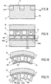
- FIGS. 11 and 12 another embodiment of the method according to the invention, leading to a circuit regenerative in which the thermal barrier 13 of the circuit of FIG. 10 is replaced by a finned heat exchanger radial fins 19B forming between them longitudinal channels 195B, the radial fins 19B having a low height h such that the ratio between the height h of the radial fins 19B and the width l of these fins is less than or equal to 1.
- the step of producing an intermediate layer 12 on the support mandrel 11 takes place after the step of forming a series of 120 channels regularly distributed around the mandrel 11, in which the channels 120 in the form of grooves are machined from the outside in the mandrel support 11 and provided with inserts as indicated above, in particular with reference to FIG. 13.
- method comprises, after the step of forming an intermediate layer 12 on the support mandrel 11, an additional step of machining in the intermediate layer 12 outer grooves 196 having a height h and a width l such that h / l ⁇ 1, in order to allow the formation of radial fins 19B during the subsequent step of realization of the body 14 of the structure 10 by thermal spraying.
- the spaces 195B between the fins 19B are occupied by the material of the intermediate layer 12 to the dissolution of it and do not contribute to the definition of canals opening opposite the intermediate layer 12 contrary to spaces 195A of FIG. 9.
- the presence of the channels 120 at the periphery of the support mandrel 11 is therefore indispensable and not optional.
- Figure 11 shows the appearance of a wall portion manufactured according to the process illustrated with reference to FIG. 12, after dissolution of the intermediate layer 12.
Landscapes
- Engineering & Computer Science (AREA)
- Chemical & Material Sciences (AREA)
- Mechanical Engineering (AREA)
- Combustion & Propulsion (AREA)
- General Engineering & Computer Science (AREA)
- Physics & Mathematics (AREA)
- Plasma & Fusion (AREA)
- Chemical Kinetics & Catalysis (AREA)
- Materials Engineering (AREA)
- Metallurgy (AREA)
- Organic Chemistry (AREA)
- Coating By Spraying Or Casting (AREA)
Description
La présente invention concerne un procédé de fabrication d'un circuit régénératif à fort flux thermique comprenant une structure avec une surface fonctionnelle interne en contact avec un premier fluide , et un ensemble de canaux formés dans le corps de la structure pour être parcourus par un second fluide en relation d'échange thermique avec le premier fluide , le procédé consistant à construire la structure autour d'un mandrin support réutilisable, à partir de ladite surface fonctionnelle interne, par des opérations de projection thermique et d'usinage.The present invention relates to a method of manufacturing a regenerative circuit with a high thermal flux comprising a structure with a internal functional surface in contact with a first fluid, and a set of channels formed in the body of the structure to be traveled by a second fluid in heat exchange relationship with the first fluid, the process of constructing the structure around a reusable support mandrel, from said functional surface internal, by thermal projection and machining operations.
L'invention concerne également un circuit régénératif à fort flux thermique obtenu par le procédé, tel qu'une chambre de combustion de moteur-fusée.The invention also relates to a high flux regenerative circuit obtained by the process, such as a combustion chamber of rocket engine.
Des structures constituant des circuits régénératifs à fort flux thermique sont utilisées dans différents contextes, par exemple pour des échangeurs de chaleur, des aubes refroidies par circulation de liquide ou des parois d'enceintes de combustion.Structures constituting regenerative circuits with high flux are used in different contexts, for example for heat exchangers, blades cooled by circulation of liquid or combustion chamber walls.
Ainsi, les parois des enceintes de combustion telles que les chambres de combustion et les tuyères des moteurs-fusées, notamment à propergols liquides, qui sont en contact avec des gaz de combustion constituant un milieu de température élevée, sont en général refroidies pendant leur fonctionnement.Thus, the walls of the combustion chambers such as the combustion chambers and nozzles of rocket engines, particularly liquid propellants, which are in contact with combustion gases constituting a medium of high temperature, are generally cooled during their operation.
Un mode de refroidissement courant consiste à munir les parois d'enceintes de canaux de refroidissement. Ceci est le cas dans des lanceurs de satellites et avions spatiaux, mais également dans des propulseurs de satellites, des réacteurs nucléaires et des chaudières de haut rendement, et peut encore être le cas dans des boucliers thermiques ou nez d'engins volant à grande vitesse.A common cooling mode is to provide the walls of cooling channel enclosures. This is the case in launchers of satellites and space planes, but also in satellite thrusters, nuclear reactors and boilers high efficiency, and may still be the case in heat shields or nose of gear flying at high speed.
On a ainsi déjà proposé, notamment dans le cadre de moteurs-fusées, divers procédés de fabrication de parois de chambres de combustion permettant d'intégrer des canaux de refroidissement orientés en direction longitudinale, dans lesquels circule un fluide de refroidissement qui peut être l'un des ergols servant à alimenter le moteur-fusée, le système de refroidissement étant ainsi à régénération. It has already been proposed, particularly in the context of rocket engines, various methods of manufacturing chamber walls combustion to integrate oriented cooling channels in the longitudinal direction, in which circulates a fluid of cooling which can be one of the propellants used to power the rocket engine, the cooling system is thus regenerating.
Les techniques de fabrication de telles chambres de combustion sont cependant délicates à mettre en oeuvre, longues et coûteuses.The techniques of manufacturing such combustion chambers However, they are delicate to implement, long and expensive.
Dans certaines applications particulières, il est également utile de pouvoir réchauffer une enceinte froide, par circulation d'un fluide chaud dans les passages ménagés dans la paroi de l'enceinte qui constitue aussi également un circuit régénératif.In some particular applications, it is also useful to to be able to heat a cold chamber, by circulation of a hot fluid in the passages in the wall of the enclosure which constitutes also a regenerative circuit.
Selon une première technique de fabrication de chambres de combustion refroidies par régénération pour moteurs-fusées à propergols liquides, des canaux de refroidissement sont usinés dans un corps de base interne formé d'une seule pièce à partir d'un matériau métallique bon conducteur de la chaleur, tel que du cuivre. Les canaux de refroidissement sont ainsi séparés les uns des autres par des cloisons du corps de base et un couvercle externe est réalisé par électrodéposition de multiples couches de nickel en alternance avec des reprises d'usinage obligatoires entre chaque passe d'électrodéposition. L'obturation des canaux avant l'électrodéposition est obtenue par application d'une résine conductrice.According to a first technique of manufacturing chambers of regeneration-cooled combustion for rocket propellant engines liquid, cooling channels are machined in a body of internal base formed in one piece from a good metallic material heat conductor, such as copper. The channels of cooling are thus separated from each other by partitions of the base body and an outer cover is made by electroplating multiple layers of nickel alternating with machining required between each electroplating pass. Clogging channels before plating is obtained by applying a resin conductive.
On a représenté sur la figure 14 un exemple de paroi de chambre de combustion réalisée selon cette technique.FIG. 14 shows an example of a chamber wall combustion produced by this technique.
Une chemise interne 104, qui est réalisée par forgeage, par
exemple en un matériau métallique tel que du Narloy Z, comporte des
canaux de refroidissement 105 réalisés par usinage.An
Une couche 107 d'obturation des canaux 105 est formée par
électrodéposition et est elle-même recouverte de nickel également
déposé par électrodéposition. Divers éléments de la coque extérieure 109
en superalliage tel que par exemple de l'inconel-718, sont assemblés au
niveau de joints 110 par soudure par faisceau d'électrons.A
La mise en forme de la chemise interne 104 de la chambre de
combustion, ainsi que la fermeture des canaux 105 par électrodéposition
constituent des inconvénients majeurs de ce procédé. En effet ces
opérations sont longues et coûteuses. D'autre part chacune des soudures
110, utilisées pour l'assemblage final des composants de la chambre,
constitue un risque potentiel de rupture. Ce sont ces désavantages que
l'on cherche à supprimer par le recours au procédé de plasma-formage,
selon une deuxième technique de fabrication de chambres de
combustion.The shaping of the
On a représenté sur la figure 15 un exemple de paroi de chambre de combustion réalisée selon cette deuxième technique de fabrication connue consistant à réaliser tout ou partie de la structure de la chambre de combustion par projection thermique de poudres d'alliages définis.FIG. 15 shows an example of a chamber wall of combustion produced according to this second manufacturing technique known to achieve all or part of the structure of the chamber thermal spray combustion of powders of defined alloys.
Selon un exemple de tel procédé selon lequel la paroi de la chambre de combustion est réalisée en partant de l'intérieur et en allant vers l'extérieur de la chambre, on procède à la fabrication d'un mandrin 1 de projection en acier doux usiné selon les cotes intérieures de la chambre de combustion à obtenir.According to an example of such a method according to which the wall of the combustion chamber is carried out from the inside and going towards the outside of the chamber, we proceed to the manufacture of a mandrel 1 made of mild steel machined according to the internal dimensions of the combustion chamber to get.
Une première projection sous vide partiel permet alors de réaliser à
la surface du mandrin 1 la chemise 4 en alliage de cuivre (Narloy Z...) de
la future chambre. L'opération suivante consiste à y usiner les canaux de
refroidissement 5, et à y introduire un matériau de remplissage
consommable. Après suppression par usinage des excès de remplissage,
une seconde projection sous vide partiel de l'alliage de cuivre permet de
former une couche 7 de fermeture des canaux. Dans la foulée, la coque 8
en superalliage est directement construite par projection thermique sur la
chemise en cuivre. La dernière opération consiste à éliminer par voie
chimique le matériau de remplissage, de façon à libérer les canaux 5,
ainsi qu'à éliminer le mandrin de projection 1.A first partial vacuum projection then makes it possible to realize
the surface of the mandrel 1 the
On connaít également par le document "Adherent Thermal Barrier for Combustion Chamber", NTIS TECH NOTES, page 155, Février 1990, Springfield, VA, USA, un procédé de fabrication d'un circuit régénératif pour chambre de combustion de moteur-fusée, selon lequel un mandrin en aluminium est usiné à la forme cylindrique requise, une couche de barrière thermique en zirconium stabilisé par de l'yttrium est projetée par plasma sur le mandrin, une couche de nickel-chrome est projetée sur la couche précédente pour former une couche de liaison électriquement conductrice, une couche de cuivre est ajoutée par électroformage, des gorges longitudinales sont usinées dans la couche de cuivre, les gorges sont remplies de cire, une couche de cuivre finale est ajoutée par électroformage, la cire est éliminée par fusion et le mandrin en aluminium est détruit.It is also known from the document "Adherent Thermal Barrier for Combustion Chamber ", NTIS TECH NOTES, page 155, February 1990, Springfield, VA, USA, a method of manufacturing a regenerative circuit for a rocket motor combustion chamber, according to which a mandrel aluminum is machined to the required cylindrical shape, a layer of zirconium thermal barrier stabilized with yttrium is projected by plasma on the mandrel, a layer of nickel-chromium is projected onto the previous layer to form an electrically bonding layer conductor, a layer of copper is added by electroforming, longitudinal grooves are machined in the copper layer, the grooves are filled with wax, a final copper layer is added by electroforming, the wax is removed by melting and the aluminum mandrel is destroyed.
On a également déjà proposé de réaliser un mandrin support en plusieurs parties qui peut ainsi être réutilisable. A titre d'exemple, un mandrin est constitué de deux cônes en acier inoxydable séparés l'un de l'autre par une rondelle en acier doux, l'ensemble étant recouvert par un dépôt d'acier. Une fois la fabrication de la chambre de combustion terminée, la dissolution des inserts placés dans les canaux de refroidissement s'accompagne de celle de la rondelle et du dépôt d'acier. Les deux cônes peuvent alors être démontés et récupérés.It has also already been proposed to produce a support mandrel in several parts that can be reusable. For example, a mandrel consists of two separate stainless steel cones one of the other by a soft steel washer, the whole being covered by a steel deposit. Once the manufacture of the combustion chamber completed, the dissolution of the inserts placed in the channels of cooling is accompanied by that of the washer and the steel deposit. The two cones can then be disassembled and recovered.
Les procédés connus restent cependant peu satisfaisants, notamment du fait de lenteurs dans les processus de dissolution des inserts et d'élimination des couches provisoires, et de difficultés à réaliser de façon optimale des structures de grande dimension. The known methods, however, remain unsatisfactory, in particular because of delays in the processes of dissolution of inserts and elimination of temporary layers, and difficulties in achieving optimally large structures.
L'invention a pour objet de remédier aux inconvénients précités et de permettre la fabrication de structures de circuits régénératifs de façon plus commode que dans les procédés de l'art antérieur tout en permettant une optimisation des caractéristiques des structures fabriquées, même dans le cas de structures de grandes dimensions soumises à de forts flux thermiques.The object of the invention is to remedy the aforementioned drawbacks and to allow the manufacture of regenerative circuit structures so more convenient than in the methods of the prior art while allowing an optimization of the characteristics of the fabricated structures, even in the case of large structures subject to high flux thermal.
Ces buts sont atteints, conformément à l'invention, grâce à un
procédé de fabrication d'un circuit régénératif à fort flux thermique
comprenant une structure avec une surface fonctionnelle interne en
contact avec un premier fluide, et un ensemble de canaux formés dans le
corps de la structure pour être parcourus par un second fluide en relation
d'échange thermique avec le premier fluide , le procédé comprenant les
étapes suivantes :
Selon une caractéristique préférentielle, avant l'étape de remplissage de canaux usinés dans le corps de la structure ou autour du mandrin support, des inserts filaires ou tubulaires, de préférence en matière plastique, comme une résine polyamide par exemple, sont introduits dans le fond des gorges formant les canaux pour permettre la formation ultérieure de cavités sous les inserts solubles dans le fond des canaux. Le retrait des inserts filaires est effectué avant l'étape suivante de projection thermique.According to a preferred characteristic, before the step of filling of machined channels in the body of the structure or around the support mandrel, wire or tubular inserts, preferably in plastic material, such as a polyamide resin for example, are introduced into the bottom of the grooves forming the channels to allow the subsequent formation of cavities under soluble inserts in the bottom of canals. The withdrawal of the wired inserts is carried out before the next step of thermal projection.
Selon un mode particulier de réalisation, l'étape de remplissage des canaux du corps de la structure à l'aide d'inserts solubles consiste en une opération de remplissage incomplet des canaux suivie d'une étape de projection thermique d'un matériau métallique qui termine le remplissage des canaux et forme une couche métallique recouvrant également les nervures de séparation des canaux, puis d'une étape d'usinage superficiel de ladite couche métallique jusqu'à la mise à nu de l'extrémité libre desdites nervures.According to a particular embodiment, the step of filling the channels of the body of the structure using soluble inserts consists of a Incomplete filling operation of the channels followed by a step of thermal projection of a metallic material that completes the filling channels and forms a metal layer also covering the channel separation ribs, then a superficial machining step from said metal layer to the exposed end of the free end said ribs.
Dans le cas de la fabrication de structures de grandes dimensions, lors des opérations de projection thermique avec préchauffage du mandrin support à une température supérieure à environ 850°C, on procède pendant toute l'opération de projection thermique, à un apport de chaleur complémentaire par un dispositif de chauffage additionnel voisin du mandrin supportIn the case of the manufacture of large structures, during thermal spraying operations with preheating support mandrel at a temperature greater than about 850 ° C, proceeds during the entire thermal projection operation, to a contribution of additional heat by a neighboring additional heating device of the mandrel
Selon des caractéristiques particulières de l'invention :
- on réalise le corps de la structure par projection thermique d'une poudre d'alliage Cu-Ag-Zr,
- on réalise le mandrin support en cuivre pur,
- on réalise la couche intermédiaire par projection thermique d'une poudre de fer,
- les inserts filaires sont constitués par des fils à base de résine polyamide,
- l'étape de projection thermique d'un matériau métallique qui termine le remplissage des canaux consiste en la projection thermique d'une poudre de fer sous vide ou sous basse pression au moyen d'une torche à plasma,
- l'étape de formation d'une couche de fermeture des canaux du corps de la structure consiste en la projection thermique d'une poudre d'alliage de Cu-Ag-Zr et l'étape de formation d'une enveloppe externe consiste en la projection thermique d'une poudre d'alliage à base de nickel tel qu'un alliage à base de nickel-cuivre constitué par le MONEL K 500 ou NU30AT.
- l'étape de suppression des inserts solubles des canaux du corps de la structure ou des canaux du mandrin est réalisée par circulation d'un fluide tel que de préférence de l'acide chlorhydrique.
- the body of the structure is made by thermal spraying a Cu-Ag-Zr alloy powder,
- the pure copper support mandrel is produced,
- the intermediate layer is produced by thermal spraying of an iron powder,
- the wire inserts consist of polyamide resin-based wires,
- the step of thermal spraying of a metallic material which terminates the filling of the channels consists in the thermal spraying of an iron powder under vacuum or at low pressure by means of a plasma torch,
- the step of forming a closure layer of the channels of the body of the structure consists of the thermal spraying of a Cu-Ag-Zr alloy powder and the step of forming an outer envelope consists of thermal spraying of a nickel-based alloy powder such as a nickel-copper alloy consisting of MONEL K 500 or NU30AT.
- the step of removing the soluble inserts from the channels of the body of the structure or channels of the mandrel is achieved by circulation of a fluid such as preferably hydrochloric acid.
Le procédé peut comprendre une étape supplémentaire de
formation d'une couche de cuivre poreux par projection thermique réalisée
entre la formation de la couche de fermeture des canaux du corps de la
structure et l'étape de formation d'une enveloppe externe.
Selon un premier mode de réalisation avantageux de l'invention, l'étape c)
de formation d'une série de canaux régulièrement répartis autour du
mandrin a lieu avant l'étape b) de réalisation d'une couche intermédiaire
et comprend l'usinage par l'extérieur dans le mandrin support, après son
montage sur ledit axe de rotation, de canaux en forme de gorges, et le
remplissage desdits canaux du mandrin support à l'aide d'inserts solubles
comprenant un mélange d'un liant organique et de poudre métallique.The method may comprise an additional step of forming a porous copper layer by thermal spraying performed between the formation of the channel closure layer of the body of the structure and the step of forming an outer envelope.
According to a first advantageous embodiment of the invention, step c) of forming a series of regularly distributed channels around the mandrel takes place before step b) of producing an intermediate layer and comprises machining from outside in the support mandrel, after mounting on said axis of rotation, groove-like channels, and filling said channels of the support mandrel with soluble inserts comprising a mixture of an organic binder and of metal powder.
Dans ce cas, le procédé peut comprendre en outre, après l'étape de réalisation d'une couche intermédiaire, l'étape supplémentaire consistant en la réalisation, par projection thermique, sous vide ou sous basse pression au moyen d'une torche plasma, d'une couche de faible rugosité d'un matériau formant barrière thermique de type métallique ou oxydes.In this case, the method may further comprise, after the step of making an intermediate layer, the additional step consisting of the production, by thermal spraying, under vacuum or under low pressure by means of a plasma torch, a weak layer roughness of a metal-type thermal barrier material or oxides.
A titre d'exemple, on peut réaliser la barrière thermique par projection thermique d'une poudre d'un superalliage tel que du MCrAIYTa.For example, it is possible to realize the thermal barrier by thermal spraying of a powder of a superalloy such as MCrAIYTa.
Avantageusement, on réalise la barrière thermique en projetant en outre avant le superalliage une poudre de zircone ytriée pour former une couche superficielle de ce matériau.Advantageously, the thermal barrier is produced by projecting in addition to the superalloy a zirconia powder ytriée to form a superficial layer of this material.
Selon un autre mode particulier de réalisation, l'étape c) de formation d'une série de canaux régulièrement répartis autour du mandrin a lieu après l'étape b) de réalisation d'une couche intermédiaire et comprend le dépôt d'un alliage à base de cuivre sur la couche intermédiaire, l'usinage de l'alliage à base de cuivre pour définir des ailettes radiales entre lesquelles sont ménagés des interstices constituant lesdits canaux, et le remplissage desdits canaux à l'aide d'inserts solubles comprenant un mélange d'un liant organique et de poudre métallique.According to another particular embodiment, step c) of formation of a series of channels regularly distributed around the mandrel after step b) of producing an intermediate layer and includes the deposition of a copper-based alloy on the layer intermediate, machining the copper-based alloy to define radial fins between which are formed interstices constituting said channels, and filling said channels with soluble inserts comprising a mixture of an organic binder and metal powder.
Dans ce cas, le procédé peut comprendre en outre une étape consistant à déposer une couche de fer supplémentaire qui comble une partie restée libre dans les canaux au-dessus des inserts solubles et recouvre également les ailettes et une étape consistant à usiner ladite couche de fer supplémentaire pour faire émerger les ailettes à base de cuivre et ne conserver qu'une mince couche de fer au-dessus de chaque insert soluble, cette couche étant alignée avec la face libre des ailettes.In this case, the method may further comprise a step depositing an extra layer of iron that fills a part remained free in the canals above the soluble inserts and also covers the fins and a step of machining said extra layer of iron to make the fins emerge from copper and keep only a thin layer of iron over each soluble insert, this layer being aligned with the free face of the fins.
Ce deuxième mode de réalisation conduit à une structure de circuit régénératif du type échangeur thermique à ailettes.This second embodiment leads to a circuit structure regenerative type finned heat exchanger.
On notera qu'à titre de variante, il est possible de réaliser également une structure de circuit régénératif du type échangeur thermique à ailettes dans le cadre du premier mode de réalisation dans lequel l'étape c) de formation d'une série de canaux régulièrement répartis autour du mandrin a lieu avant l'étape b) de réalisation d'une couche intermédiaire, les canaux en forme de gorges étant usinés par l'extérieur dans le mandrin support.It will be noted that, as a variant, it is possible to realize also a regenerative circuit structure of the exchanger type finned heat as part of the first embodiment in which step c) of forming a series of regularly distributed channels around the mandrel takes place before step b) of producing a layer intermediate, groove-shaped channels being machined from the outside in the support mandrel.
Selon cette variante de réalisation, le procédé comprend en outre, après l'étape b) de formation d'une couche intermédiaire sur le mandrin support, une étape supplémentaire b1) consistant à usiner dans la couche intermédiaire des rainures extérieures présentant une hauteur h et une largeur ℓ telles que h/ℓ ≤ 1, en vue de former des ailettes radiales lors de l'étape de réalisation du corps de la structure par projection thermique.According to this variant embodiment, the method further comprises, after step b) of forming an intermediate layer on the support mandrel, an additional step b 1 ) of machining in the intermediate layer external grooves having a height h and a width ℓ such that h / ℓ ≤ 1, in order to form radial fins during the step of producing the body of the structure by thermal spraying.
Ainsi, cette variante du premier mode de réalisation du procédé selon l'invention permet de réaliser des ailettes radiales de faible hauteur, mais ne délimitent pas elles-mêmes les canaux principaux débouchant en regard de la couche intermédiaire, ceux-ci restant formés par usinage par l'extérieur dans le mandrin support.Thus, this variant of the first embodiment of the method according to the invention makes it possible to achieve radial fins of low height, but do not themselves delimit the main channels leading to intermediate layer, these remaining formed by machining by outside in the support mandrel.
Le procédé selon l'invention peut être appliqué d'une façon générale à la fabrication d'une structure constituée par un échangeur de chaleur.The process according to the invention can be applied in a the construction of a structure consisting of a heat exchanger heat.
Le procédé selon l'invention est particulièrement adapté à la fabrication d'une structure constituée par une chambre de combustion à haut flux thermique, telle qu'une chambre de combustion et une tuyère de moteur-fusée, en particulier d'un moteur-fusée de forte puissance de type cryogénique.The process according to the invention is particularly suitable for manufacture of a structure constituted by a combustion chamber at high heat flux, such as a combustion chamber and a nozzle of rocket motor, in particular a high power rocket motor type cryogenic.
L'invention concerne également les circuits régénératifs obtenus selon les divers modes de réalisation du procédé de fabrication susmentionné.The invention also relates to the regenerative circuits obtained according to the various embodiments of the manufacturing method above.
D'autres caractéristiques et avantages de l'invention ressortiront de la description détaillée de modes particuliers de réalisation, donnés à titre d'exemples, en référence aux dessins annexés, sur lesquels :
- la figure 1 est une section d'une paroi de circuit régénératif réalisée selon le procédé de fabrication conforme à l'invention et montrant d'une part différents éléments constitutifs définitifs du circuit régénératif et d'autre part différents éléments présents temporairement au cours de la mise en oeuvre du procédé,
- la figure 2 est une vue schématique montrant un exemple d'installation pour la mise en oeuvre du procédé selon l'invention,
- les figures 3 à 5 montrent des sections d'une paroi de circuit régénératif à différents stades du procédé de fabrication selon l'invention,
- la figure 6 montre, en coupe axiale, un exemple de mandrin support réutilisable pouvant être utilisé lors de la mise en oeuvre du procédé selon l'invention,
- la figure 7 est une section selon la ligne VII-VII de la figure 6,
- la figure 8 est une vue agrandie d'une partie de la figure 7 montrant une partie du processus de fabrication du mandrin support réutilisable,
- la figure 9 est une section d'une paroi de circuit régénératif montrant une partie du processus de fabrication dans le cas d'un mode de réalisation particulier appliqué à la fabrication d'une paroi à échangeur thermique à ailettes,
- la figure 10 est une section d'une paroi finale de circuit régénératif selon l'invention du type à barrière thermique,
- la figure 11 est une section d'une paroi finale de circuit régénératif selon l'invention du type à échangeur thermique à ailettes,
- la figure 12 est une section d'une paroi de circuit régénératif montrant une partie du processus de fabrication dans le cas d'un autre mode de réalisation particulier appliqué à la fabrication d'une paroi à échangeur thermique à ailettes,
- la figure 13 est un organigramme indiquant la succession des étapes principales d'un exemple de mise en oeuvre du procédé de fabrication selon l'invention,
- la figure 14 est une section d'une paroi de circuit régénératif fabriqué selon un procédé connu utilisant la galvanoplastie, et
- la figure 15 est une section d'une paroi de circuit régénératif fabriqué selon un procédé connu utilisant le plasma-formage.
- FIG. 1 is a section of a regenerative circuit wall made according to the manufacturing method according to the invention and showing, on the one hand, different final constitutive elements of the regenerative circuit and, on the other hand, various elements temporarily present during the implementation of the method,
- FIG. 2 is a schematic view showing an example of an installation for implementing the method according to the invention,
- FIGS. 3 to 5 show sections of a regenerative circuit wall at different stages of the manufacturing method according to the invention,
- FIG. 6 shows, in axial section, an exemplary reusable support mandrel that can be used during the implementation of the method according to the invention,
- FIG. 7 is a section along the line VII-VII of FIG. 6,
- FIG. 8 is an enlarged view of a portion of FIG. 7 showing a part of the manufacturing process of the reusable support mandrel,
- FIG. 9 is a section of a regenerative circuit wall showing a part of the manufacturing process in the case of a particular embodiment applied to the manufacture of a finned heat exchanger wall,
- FIG. 10 is a section of a final wall of regenerative circuit according to the invention of the thermal barrier type,
- FIG. 11 is a section of a final wall of regenerative circuit according to the invention of the finned heat exchanger type,
- FIG. 12 is a section of a regenerative circuit wall showing part of the manufacturing process in the case of another particular embodiment applied to the manufacture of a finned heat exchanger wall,
- FIG. 13 is a flowchart indicating the succession of the main steps of an exemplary implementation of the manufacturing method according to the invention,
- Fig. 14 is a section of a regenerative circuit wall made by a known method using electroplating, and
- Fig. 15 is a section of a regenerative circuit wall made by a known method using plasma-forming.
On décrira la mise en oeuvre de modes particuliers de réalisation du procédé selon l'invention en référence à la fabrication de circuits régénératifs à forts flux thermiques constitués par des structures creuses définissant des chambres de combustion ou tuyères de moteur-fusée.We will describe the implementation of particular modes of realization of the method according to the invention with reference to the manufacture of circuits regenerative systems with strong heat flows constituted by hollow structures defining combustion chambers or rocket engine nozzles.
On voit sur la figure 2 un exemple d'une telle tuyère 30 de moteur-fusée
en forme de sablier comprenant de façon classique une partie
amont 31 formant la chambre de combustion proprement dite et
convergent vers un col de tuyère 32 lui-même prolongé par une partie
aval divergente 33. Dans le cas d'un moteur-fusée à ergols liquides, les
ergols sont injectés dans la partie amont 31 formant chambre de
combustion et les gaz résultant de la combustion sont évacués par le col
32 et le divergent 33 de la tuyère pour créer l'effort de poussée
nécessaire. La paroi de la tuyère 30 est munie de canaux 150
essentiellement longitudinaux qui sont parcourus par un fluide de
refroidissement, qui peut être l'un des ergols, pour procéder à un
refroidissement de la paroi de la tuyère 30 dont la face interne est en
contact avec les gaz chauds. Les canaux 150 doivent présenter une
géométrie bien définie et être répartis sur tout le pourtour de la tuyère 30
pour assurer un échange thermique qui optimise les performances. C'est
pourquoi le procédé de fabrication du circuit régénératif constitué par la
tuyère 30 est particulièrement important pour assurer une fabrication de
haute qualité tout en limitant les coûts.FIG. 2 shows an example of such a
Le procédé de fabrication selon l'invention consiste à élaborer par projection thermique les matériaux structuraux depuis la surface fonctionnelle de la paroi de la structure qui est située du côté des gaz chauds.The manufacturing process according to the invention consists in producing by thermal spraying the structural materials from the surface functional structure wall that is located on the gas side hot.
Dans le cas d'une chambre de combustion, la construction depuis la surface fonctionnelle située du côté des gaz chauds revient à réaliser la structure en partant du profil intérieur et en allant jusqu'à l'enveloppe externe. Une telle démarche est adaptée aussi bien à des chambres présentant une très faible section interne de passage des gaz, qu'à des chambres de grandes dimensions.In the case of a combustion chamber, the construction since the functional surface located on the hot gas side is to realize the structure starting from the inner profile and going up to the envelope external. Such an approach is adapted to rooms as well having a very small internal section for the passage of gases, only at large rooms.
La première étape du procédé selon l'invention consiste à réaliser
un mandrin support 11 dont la surface externe représente le profil intérieur
de la structure 10 à réaliser. On a représenté sur les figures 6 et 7 un
exemple de mandrin support 11 qui est conçu pour être réutilisable et sert
d'outillage pour les différentes opérations de projection thermique et
d'usinage intervenant au cours de la fabrication de la structure 10
constituée à titre d'exemple par la tuyère 30.The first step of the process according to the invention consists in producing
a
Le mandrin 11 est réalisé en deux parties 111, 112 qui sont en
contact l'une avec l'autre au niveau de la partie dont la section est la plus
étroite et correspond au col de la tuyère à fabriquer. Les deux parties 111,
112 peuvent être réunies par emboítement, au niveau de leurs parties
terminales 111A, 112A situées au niveau du col. Le mandrin 11 est
traversé par un arbre 113 centré sur l'axe longitudinal du mandrin 11.
L'arbre central 113 est lui-même solidaire d'un arbre 114 engagé dans un
logement 115 et claveté sur la partie de mandrin 111 pour assurer
l'entraínement en rotation du mandrin 11 à partir d'un plateau mobile 21
(figure 2) dont est solidaire l'arbre 114. Un système d'assemblage 118 par
exemple du type vis-écrou disposé dans un logement 116 de la partie de
mandrin 112 à l'extrémité de l'arbre 113 assure avec une rondelle 117 la
solidarisation des deux parties de mandrin 111, 112.The
Le mandrin 11 est réalisé en un matériau dont le coefficient de
dilatation thermique est très proche, ou légèrement supérieur à celui du
matériau du corps de la structure auquel il doit donner le profil. Ceci
permet d'obtenir un profil rigoureux sans écarts dus à la dilatation du
mandrin support 11 et réduit fortement les niveaux de contrainte lors des
opérations de dépôt de matière.The
A titre d'exemple, si le corps 14 d'un circuit régénératif est en
alliage Cu-Ag-Zr, le mandrin 11 peut être réalisé en cuivre pur.For example, if the
Selon un autre aspect du procédé selon l'invention, après
réalisation du mandrin et avant de commencer les opérations de dépôt
d'un matériau pour la réalisation de la structure 10 à fabriquer, on dispose
sur toute la surface extérieure du mandrin 11 une couche intermédiaire 12
(figures 1 et 3 à 5) qui est réalisée en un matériau différent de celui du
mandrin 11 et de celui de la structure 10 à réaliser et qui peut être détruite
par dissolution chimique à la fin du processus de fabrication de la
structure 10 pour permettre la séparation de la structure 10 réalisée et du
mandrin 11, sans détruire ce dernier qui peut ainsi être réutilisable et peut
être facilement retiré grâce à sa constitution en deux parties dissociables
111, 112 (figure 6).According to another aspect of the method according to the invention, after
realization of the chuck and before starting the deposit operations
of a material for the realization of the
La couche intermédiaire 12 de séparation du mandrin 11 et de la
structure 10 peut par exemple être réalisée en fer. Le dépôt peut être
réalisé par projection thermique d'une poudre de fer sous vide ou faible
pression à l'aide d'une torche au plasma 23 commandée par un robot 22,
le mandrin support 11 étant placé verticalement sur un plateau tournant
21 et rendu solidaire en rotation de celui-ci par l'arbre d'accouplement 114
(figures 2 et 6). Le procédé de projection thermique sous vide par torche
au plasma, encore appelé procédé VPS ("vacuum plasma spraying") est
connu en lui-même et ne nécessite donc pas de description plus détaillée.The
Selon un mode particulier de réalisation de l'invention, afin de
faciliter et accélérer la dissolution de la couche intermédiaire 12 pour
assurer la séparation et le dégagement du mandrin 11 à la fin du
processus de fabrication de la structure 10, on réalise dans la surface
périphérique extérieure du mandrin 11 monté sur le plateau tournant 21
des canaux longitudinaux 120 en forme de gorges usinées dans le
mandrin. Avant le dépôt de la couche intermédiaire 12 sur le mandrin 11,
des inserts filaires en matière plastique, par exemple en matériau à base
de résine polyamide, sont disposés dans le fond des gorges 120 puis les
canaux 120 sont remplis d'inserts solubles 122 comprenant un mélange
d'un liant organique et de poudre métallique (figure 8). Les inserts filaires
peuvent alors être retirés pour ménager un espace libre 121A dans le
fond des canaux 120 tandis que les inserts solubles 122 obturant les
canaux 120 permettent de procéder au dépôt de la couche intermédiaire
12.According to a particular embodiment of the invention, in order to
facilitate and accelerate the dissolution of the
La présence des canaux 120 à la périphérie du mandrin 11 et le fait
que les canaux ne soient que partiellement obturés par les inserts
solubles 122 facilite l'opération de dissolution de la couche intermédiaire
12 à la fin du processus de fabrication de la structure 10 plasmaformée.
En effet, lorsque l'on procède à la dissolution chimique par circulation d'un
fluide tel que de l'acide chlorhydrique, l'acide chlorhydrique circule
d'emblée facilement dans le fond des canaux 120 pour dissoudre d'abord
les inserts solubles 122 puis, en circulant dans les canaux 120 du mandrin
11 entièrement dégagés, assure également rapidement une dissolution de
la couche intermédiaire 12 sans avoir le temps d'attaquer le mandrin
proprement dit ou les éléments de la structure 10 réalisés en alliage à
base de cuivre ou de nickel.The presence of the
Après le dépôt de la couche intermédiaire 12 sur le mandrin
support 11 et après une éventuelle opération d'usinage pour obtenir le
profil exact de la structure 10 à fabriquer, le mandrin 11 restant sur le
plateau tournant 21, le processus de fabrication proprement dite de la
structure 10 peut commencer par la projection thermique d'une fine
couche 13 d'un matériau formant barrière thermique, sur la couche
intermédiaire 12. La présence d'une barrière thermique réalisée par
projection sur le support 11, 12, avant même la réalisation du reste de la
structure 10, permet d'avoir en final pour la surface 13 de la structure 10
une faible rugosité, dans la mesure où la rugosité du dépôt 13 est alors
conditionnée par celle de la couche intermédiaire 12.After the deposition of the
La barrière thermique 13 peut être constituée par un superalliage
ou du MCr Al Yta avec ou non présence d'une couche superficielle de
zircone ytriée.The
La barrière thermique 13 est réalisée par le même procédé de
projection thermique (VPS) que celui utilisé ensuite pour réaliser le corps
14 de la structure 10 et avec la même installation déjà décrite en
référence à la figure 2. La barrière thermique 13 permet de garantir une
bonne adhérence grâce à l'interdiffusion opérée au cours des projections
ultérieures entre cette couche et le corps 14 du circuit régénératif à base
de cuivre.The
La construction du corps 14 de la structure 10 en matériau à base
de cuivre sur le mandrin support 11 est réalisée par projection thermique ;
en l'occurrence en projection sous vide ou sous basse pression au moyen
de la torche plasma 23. La poudre métallique projetée répond aux critères
de qualité à obtenir en final pour le dépôt (composition chimique,
propriétés physiques) et est adaptée en taille de grains de poudre aux
conditions de projection. Dans le cas de la projection de Cu-Ag-Zr il s'agit
de poudre de taille inférieure à 106 µm, de préférence comprise entre 10
et 63 µm, à faible teneur en oxygène (< 150ppm).The construction of the
La projection thermique pour la fabrication du corps 14 comme
pour la formation de la barrière thermique 13 est réalisée sur le mandrin
support 11 préalablement préchauffé à plus de 850°C et cette
température doit être maintenue pendant toute la durée de la projection
thermique. Pour les composants de grande taille cette température est
maintenue au moyen d'un chauffage additionnel 24 (figure 2) qui selon le
diamètre du composant peut être un chauffage par effet joule, un
chauffage par induction ou encore un chauffage au moyen d'une torche
additionnelle non utilisée pour la projection de poudre et dont les
paramètres de fonctionnement peuvent de ce fait être optimisés pour la
seule fonction de chauffage. Cette condition de chauffage additionnel est
impérative pour obtenir un dépôt à caractéristiques mécaniques élevées.The thermal projection for the making of the
Des canaux 150 sont ensuite usinés dans le corps 14 de façon
classique mais en bénéficiant du mandrin support de projection 11 comme
outillage de positionnement. Ainsi, il n'y a pas de montage et démontage
d'outillage entre opérations successives au cours de la fabrication.
L'usinage des canaux 150 par l'extérieur est possible quelle que soit la
taille de la chambre : il n'y a pas de difficulté liée aux petites géométries
de chambres.
Le remplissage partiel des canaux 150 est effectué, comme pour
les canaux 120 du mandrin, au moyen d'inserts solubles 152 composés
d'un liant organique et de poudre métallique. Ce type d'insert s'adapte
quel que soit le profil de la structure 10 et quelles que soient les variations
de section des canaux 150. Au fond des canaux, une cavité 151A (figures
1 et 4) est aménagée, comme pour les canaux 120 du mandrin support
11, grâce à l'emploi temporaire de fils ou tubes en matière plastique 151,
par exemple à base de résine polyamide (figure 3). En pratique, les fils
151 sont retirés dès que les inserts solubles 152 ont été réalisés et
peuvent ainsi former un dégagement 151A au fond des canaux 150 avant
même l'étape suivante de dépôt d'une couche supplémentaire 16A
(contrairement à ce qui a été représenté sur la figure 3 où la couche 16A
apparaít déjà sur le dessin). La présence d'espaces libres 151A au fond
des canaux 150 joue un rôle très important lors de l'étape ultérieure de
dissolution chimique des inserts solubles 152 et du restant 16 de la
couche supplémentaire 16A, grâce à une circulation immédiate d'acide
sur la totalité de la longueur des canaux 150. Ainsi, le gain en temps pour
la dissolution chimique des inserts solubles 152 et pour les parties
résiduelles 16 de la couche supplémentaire 16A est très important,
comme dans le cas de la dissolution de la couche intermédiaire 12 qui
intervient à la fin du processus de fabrication pour retirer le mandrin 11 et
bénéficie de la circulation accélérée d'acide dans les canaux 120 du
mandrin 11.The partial filling of the
Les inserts 15 constitués par les inserts solubles 152 superposés
aux inserts filaires 151 sont placés dans les canaux 150 en ménageant à
la partie supérieure un léger retrait par rapport aux nervures 140 du corps
14 séparant les différents canaux 150 (figure 3). De la sorte, lors du dépôt
effectué ensuite d'une couche supplémentaire 16A, par exemple de fer,
par projection thermique (VPS), le dépôt de fer s'effectue avec une
adhérence suffisante grâce à l'ancrage résultant des parties 16 de la
couche 16A qui pénètrent dans la partie supérieure des canaux 150.The
Le remplissage final des canaux 150 est ainsi réalisé par projection
thermique de fer, de préférence sous vide ou à basse pression. Ce dépôt
16, après usinage superficiel jusqu'à la mise à nu du sommet des
nervures 140 du corps 14 (figure 4) assure la précision de la section des
canaux et la rugosité demandée pour la couche suivante 17.The final filling of the
Dans certains cas, si les exigences sont moindres sur la précision
de la section des canaux 150 et sur la rugosité demandée, la nouvelle
couche 17 peut être déposée directement sur le liant organique des
inserts solubles 152, qui affleure alors le sommet des nervures 140.
L'étape consistant à déposer une couche 16A et à usiner cette couche
jusqu'à ne conserver que des parties 16 achevant de combler les canaux
150 peut alors être supprimée.In some cases, if the requirements are lower on accuracy
of the
Dans tous les cas, la fermeture des canaux 150 par une couche de
matériau 17 et la construction du matériau d'une enveloppe externe 18
sont réalisés par projection thermique, en l'occurrence en projection sous
vide ou sous basse pression au moyen de la même torche plasma 23, la
structure 10 en cours de réalisation restant en place sur le mandrin 11
placé sur la table tournante 21. Comme lors de la réalisation de la barrière
thermique 13 et du corps 14, la projection thermique assurant la formation
de la couche 17 de fermeture des canaux 150 et celle de l'enveloppe
externe 18 est réalisée sur le mandrin support 11 qui est préalablement
préchauffé à plus de 850°C puis est maintenu à cette température
pendant toute la durée de la projection, le cas échéant avec apport de
chaleur par le dispositif 24 de chauffage additionnel.In all cases, the closure of the
La fermeture des canaux 150 est d'abord réalisée par exemple par
projection de poudre d'alliage de Cu-Ag-Zr, pour former une couche de
fermeture 17, puis l'enveloppe externe 18 est construite par projection par
exemple d'une poudre d'alliage à base de nickel.The closing of the
Dans le cas de la projection de Cu-Ag-Zr, la dimension des particules de la poudre peut être comprise entre 10 et 63 µm et la poudre présente une faible teneur en oxygène (< 150 ppm).In the case of Cu-Ag-Zr projection, the size of particles of the powder may be between 10 and 63 μm and the powder has a low oxygen content (<150 ppm).
Le choix optimal de l'alliage utilisé pour la réalisation de l'enveloppe
18 prend en compte la compatibilité avec la sous-couche 17 en base
cuivre (ex. : cas du Cu-Ag-Zr) en termes de possibilités de projection, de
propriétés physiques, d'interdiffusion et de similitude de cycle de
traitement thermique. Dans le cas d'une chambre à circuit régénératif en
base de cuivre, dont Cu-Ag-Zr, l'alliage retenu est de type à base de
Nickel-Cuivre (MONEL K500 ou NU30AT).The optimal choice of the alloy used for the realization of the
Comme indiqué précédemment, après la fin de la réalisation de
l'enveloppe 18, la suppression des inserts solubles 152 des canaux 150
du corps 14 de la structure 10, la suppression des inserts solubles des
canaux 120 du mandrin support 11 et la suppression des dépôts des
couches intermédiaires 12, 16 en fer, sont réalisés par circulation d'acide
chlorhydrique en milieu désaéré. Du fait de la présence de dégagements
tels que 151 dans le fond des canaux 150 du corps 14 aussi bien que
dans le fond des canaux 120 du mandrin 11, sur toute la longueur des
canaux 150, 120, la circulation de l'acide est très rapide, ce qui accélère le
processus de réalisation de la structure tout en garantissant une absence
d'attaque des éléments constitutifs définitifs de la structure 10 ou du
mandrin 11.As mentioned before, after the completion of the
the
Il est important de noter que le mandrin 11 reste solidaire de la
structure 10 durant tout le processus de fabrication et sert aussi bien
d'outillage pour les séquences de projections thermiques que pour les
étapes d'usinage. La précision de positionnement peut ainsi être très
grande et il est possible d'usiner des canaux 150 même si le corps 14
présente une très faible épaisseur de paroi, par exemple de l'ordre de 0,7
mm ou même moins.It is important to note that the
La figure 1 montre en coupe les couches constitutives d'un circuit
régénératif 10 réalisé selon l'invention, avec un barrière thermique 13, un
corps 10, une couche 17 de fermeture des canaux 150 et une enveloppe
extérieure 18. La figure 1 montre en outre les éléments intervenant
temporairement au cours du procédé de fabrication et qui ne font pas
partie de la structure finale 10, du circuit régénératif, à savoir le mandrin
support 11, une couche intermédiaire 12, des inserts 15 comprenant des
inserts filaires 151 et des inserts solubles 152, des éléments 16 d'une
couche de recouvrement des canaux 150.FIG. 1 shows in section the constituent layers of a circuit
La figure 10 montre en coupe sectorielle partielle, le produit final
obtenu avec le procédé selon l'invention dans le cas d'un circuit
régénératif avec barrière thermique réalisé de la façon décrite
précédemment. Dans ce cas, la barrière thermique 13 peut comprendre
une première barrière thermique superficielle mince 131 par exemple à
base de zircone et une deuxième barrière thermique 132 à base d'un
alliage de M Cr Al Y. La barrière thermique 13 est formée sur la face
interne de la chemise 14 en alliage de cuivre dont les canaux 150 sont
fermés par la couche 17 en alliage de cuivre, elle-même recouverte de
l'enveloppe 18 en nickel.Figure 10 shows partial sectoral section, the final product
obtained with the method according to the invention in the case of a circuit
regenerative with thermal barrier achieved in the manner described
previously. In this case, the
Selon une variante de réalisation, on peut, lors de la fabrication du
circuit régénératif, déposer par plasma formage, entre la couche 17 à
base de cuivre et la couche 18 à base de nickel, une couche poreuse 17'
par exemple de cuivre poreux, obtenue directement par projection
thermique sur la couche 17 à base de cuivre et avant le dépôt de la
couche 18 à base de nickel. Une telle couche poreuse 17' reste
optionnelle. According to an alternative embodiment, it is possible, during the manufacture of the
Regenerative circuit, plasma deposit forming, between
La figure 13 présente un organigramme comportant un résumé des
principales étapes 201 à 212 d'un exemple de mise en oeuvre du procédé
de fabrication selon l'invention.Figure 13 presents a flowchart with a summary of
L'étape 201 comprend ainsi la réalisation d'un mandrin support
profilé 11, par exemple à base de cuivre pur, destiné à être réutilisable et
pouvant être réalisé en au moins deux parties si la géométrie de la
structure à fabriquer l'exige, le mandrin étant muni de gorges ou canaux
longitudinaux 120 réalisés par usinage à sa périphérie.Step 201 thus comprises the production of a
L'étape 202 comprend la pose d'inserts dans les canaux 120 avec
la présence temporaire d'inserts filaires au fond des canaux 120, la
réalisation d'inserts solubles 122 à l'aide d'un liant organique et de
poudres, puis le retrait des inserts filaires pour former des cavités 121A au
fond des canaux 120.Step 202 includes inserting inserts into
L'étape 203 consiste en un dépôt d'une couche d'interposition 12,
sur le mandrin support 11 équipé de ses inserts solubles 122, par
projection thermique, puis en un usinage de la couche d'interposition 12
pour définir avec précision le profil intérieur de la structure 10.Step 203 consists of a deposit of an
L'étape 204 consiste en la formation d'une barrière thermique 13
par projection thermique, le support étant maintenu à une température
supérieure à 850°C.Step 204 consists of forming a
L'étape 205 comprend la formation du corps de base 14 de la
structure 10 par projection thermique, le support étant maintenu à une
température supérieure à 850 °C.Step 205 includes forming the
L'étape 206 comprend l'usinage du profil et de canaux 150 dans la
face extérieure du corps de base 14 de la structure 10.Step 206 includes machining the profile and
L'étape 207 comprend la pose d'inserts 15 dans les canaux 150
avec la présence temporaire d'inserts filaires 151 au fond des canaux 150,
la réalisation d'inserts solubles 152 à l'aide d'un liant organique et de
poudres, puis le retrait des inserts filaires 151 pour former des cavités
151A au fond des canaux 150.Step 207 includes inserting inserts into
L'étape 208 optionnelle consiste en le dépôt par projection
thermique d'une couche de fer pur 16A sur la corps de base 14 avec
ancrage de la couche dans la partie supérieure des canaux 150, la
couche 16A définissant la géométrie et la rugosité des canaux 150.The
L'étape 209, liée à l'étape 208, consiste en l'usinage de la couche
16A pour mettre à nu les extrémités des nervures 140 du corps de base
14 séparant les canaux 150.
L'étape 210 consiste en la fermeture des canaux 150 par projection
thermique pour former une couche de fermeture 17, avec une maintien du
mandrin support 11 à une température supérieure à 850°C et, toujours
avec un maintien de cette température, projection thermique d'un
matériau pour former l'enveloppe externe 18, une couche poreuse 17'
pouvant le cas échéant être déposée avant l'enveloppe externe 18.Step 210 consists of closing the
L'étape 211 consiste en l'usinage de gorges et l'usinage extérieur
de la structure 10 constituant le circuit régénératif.Step 211 consists of machining grooves and external machining
of the
L'étape 212 constitue une étape finale avec dissolution chimique
des inserts solubles encore disposés dans les canaux 120, 150 et des
couches d'interposition en fer pur 12, 16, avec circulation rapide d'acide
dans le fond des canaux 120, 150, puis récupération du mandrin support
11.Step 212 is a final step with chemical dissolution
soluble inserts still arranged in the
On décrira maintenant, en référence à la figure 9, un mode
particulier de réalisation du procédé selon l'invention, conduisant à un
circuit régénératif dans lequel la barrière thermique 13 du circuit de la
figure 10 est remplacée par un échangeur de chaleur à ailettes
comportant des ailettes radiales 19A ménageant entre elles des canaux
longitudinaux 195A.We will now describe, with reference to FIG.
particular embodiment of the method according to the invention, leading to a
regenerative circuit in which the
Dans le cas de la figure 9, après l'étape de formation d'une couche
intermédiaire de fer 12 sur le mandrin 11, d'une façon qui peut être
analogue à ce qui a été décrit plus haut, il est procédé à une étape de
dépôt d'un alliage à base de cuivre, tel que par exemple un alliage Cu-Ag-Zr,
sur la couche intermédiaire 12, puis à une étape d'usinage de l'alliage
à base de cuivre pour définir des ailettes radiales 19A entre lesquelles
sont ménagés des espaces libres ou canaux 195A. Dans le cas de ce
mode de réalisation particulier, les ailettes radiales 19A présentent une
hauteur h relativement importante et telle que le rapport entre la hauteur h
sur la largeur ℓ d'une ailette soit supérieur à 1 de manière à définir entre
les ailettes 19A des canaux 195A sensiblement équivalents aux canaux
120 formés dans le mandrin 11 dans le mode de réalisation de la figure 8.In the case of Figure 9, after the step of forming a layer
iron intermediate 12 on the
ll est ensuite procédé à un remplissage partiel des espaces libres
195A en forme de canaux d'une façon analogue aux opérations de
remplissage partiel des canaux 120 du mandrin 11 ou des canaux 150 du
corps 14 décrites plus haut. Ainsi, des inserts filaires peuvent être
introduits temporairement dans le fond des interstices 195A entre ailettes
19A pour permettre un remplissage partiel de ces interstices 195A par des
inserts solubles 192 en-dessous desquels sont formés des dégagements
191A après retrait des inserts filaires. Les inserts solubles 192 restent de
préférence en retrait par rapport aux ailettes 19A de manière à permettre
le dépôt d'une couche de fer, par le procédé VPS, cette couche comblant
la partie libre des interstices 195A sur les inserts solubles 192 et
recouvrant également les ailettes 19A.Subsequently, partial filling of the
L'étape suivante consiste à usiner la couche de fer pour faire
émerger les ailettes 19A à base de cuivre et ne conserver qu'une mince
couche 193 de fer au-dessus de chaque insert soluble 192, cette couche
193 étant alignée avec la face libre des ailettes 19A. Il est alors procédé
au dépôt d'un alliage à base de cuivre pour former le corps 14 du circuit
régénératif, puis, d'une façon identique à ce qui a été précédemment
décrit en référence aux figures 3 à 5, on procède à l'usinage des canaux
150, au remplissage partiel de ces canaux 150 au moyen d'inserts
solubles 152 comme représentés sur la figure 3, au dépôt d'une couche
de fer par le procédé VPS (comme représenté sur la figure 3) et à
l'usinage de cette couche de fer pour faire émerger les ailettes ou
nervures 140 définies entre les canaux 150 (comme représenté sur la
figure 4).The next step is to machine the iron layer to make
emerge 19A copper fins and keep only a
L'étape suivante consiste à déposer un alliage 17 à base de cuivre
puis un alliage 18 à base de nickel. A titre de variante, une couche 17' de
cuivre poreux pourrait aussi être déposée sur la couche 17 à base de
cuivre avant le dépôt de l'alliage 18 à base de nickel.The next step is to deposit a copper-based
L'étape finale consiste à faire circuler de l'acide dans les cavités
191A ménagées entre les ailettes 19A, de manière à permettre une
dissolution rapide des inserts solubles 192, des couches résiduelles de fer
193 ainsi que la couche intermédiaire 12 en fer, ce qui permet de
récupérer et réutiliser le mandrin 11.The final step is to circulate acid in the
On notera que dans le cas où l'on réalise un circuit régénératif 11
selon la variante du procédé qui vient d'être décrite en référence à la
figure 9, il existe des ailettes 19A qui permettent de définir entre elles des
cavités 195A débouchant face à la couche intermédiaire 12 formée sur le
mandrin 11. Dans ce cas, ces cavités 195A peuvent jouer le rôle des
cavités 120 du mandrin 11 et le mandrin 11 peut présenter une structure
classique non cannelée. Le procédé qui vient d'être décrit en référence à
la figure 9 reste cependant compatible avec l'utilisation d'un mandrin
cannelé tel que celui de la figure 8. Dans ce cas, il existe simplement une
première série de cavités 120 formées dans le mandrin 11 d'un côté de la
couche intermédiaire 12 et une deuxième série de cavités 195A formées
entre les ailettes 19 reliées au corps 14 de l'autre côté de la couche
intermédiaire 12.It will be noted that in the case where a
On décrira maintenant en référence aux figures 11 et 12 un autre
mode de réalisation du procédé selon l'invention, conduisant à un circuit
régénératif dans lequel la barrière thermique 13 du circuit de la figure 10
est remplacée par un échangeur de chaleur à ailettes comportant des
ailettes radiales 19B ménageant entre elles des canaux longitudinaux
195B, les ailettes radiales 19B présentant une faible hauteur h telle que la
rapport entre la hauteur h des ailettes radiales 19B et la largeur ℓ de ces
ailettes soit inférieure ou égale à 1. Dans le cas de ce mode de réalisation
particulier, l'étape de réalisation d'une couche intermédiaire 12 sur le
mandrin support 11 a lieu après l'étape de formation d'une série de
canaux 120 régulièrement répartis autour du mandrin 11, dans laquelle
les canaux 120 en forme de gorges sont usinés par l'extérieur dans le
mandrin support 11 et munis d'inserts comme indiqué plus haut,
notamment en référence à la figure 13.We will now describe with reference to FIGS. 11 and 12 another
embodiment of the method according to the invention, leading to a circuit
regenerative in which the
Selon le mode particulier de réalisation illustré sur la figure 12, le
procédé comprend, après l'étape de formation d'une couche intermédiaire
12 sur le mandrin support 11, une étape supplémentaire consistant à
usiner dans la couche intermédiaire 12 des rainures extérieures 196
présentant une hauteur h et une largeur ℓ telles que h/ℓ ≤ 1, en vue de
permettre la formation d'ailettes radiales 19B lors de l'étape ultérieure de
réalisation du corps 14 de la structure 10 par projection thermique.According to the particular embodiment illustrated in FIG.
method comprises, after the step of forming an
Dans ce cas, les espaces 195B entre les ailettes 19B sont
occupés par le matériau de la couche intermédiaire 12 jusqu'à la
dissolution de celle-ci et ne contribuent pas à définir des canaux
débouchant en regard de la couche intermédiaire 12 contrairement aux
espaces 195A de la figure 9. Dans le mode de réalisation de la figure 12,
la présence des canaux 120 à la périphérie du mandrin support 11 est
donc indispensable et non facultative.In this case, the
La figure 11 montre l'aspect d'une portion de paroi fabriquée selon
le procédé illustré en référence à la figure 12, après dissolution de la
couche intermédiaire 12.Figure 11 shows the appearance of a wall portion manufactured according to
the process illustrated with reference to FIG. 12, after dissolution of the
Claims (22)
- A method of manufacturing a high heat flux regenerative circuit comprising a structure (10) having an inner functional surface (13) in contact with a first fluid and a set of channels (150) formed in the body (14) of the structure (10) for conveying a second fluid in heat exchange relationship with the first fluid, the method comprising the following steps:a) placing a reusable support core (11) representing the profile of said inner functional surface (13) of the structure (10) about an axis of rotation (113), the support core (11) being made of a material whose coefficient of thermal expansion is very close to or slightly greater than that of a material of the body (14) of the structure (10);b) making an intermediate layer (12) on the support core (11) out of a material that is different from that of the support core (11) and that of the body (14) of the structure (10);c) forming a series of channels (120; 195A) regularly spaced apart around the core (11) and opening out to face said intermediate layer (12), each of the channels (120; 195A) being provided with a soluble insert comprising a mixture of organic binder and metal powder;d) preheating the support core (11) to a temperature greater than about 850°C and making the body (14) of the structure (10) by thermal spraying under a vacuum or low pressure by means of a plasma torch, while maintaining the temperature of the support core (11) at said temperature greater than 850°C;e) without dismantling the support core (11), machining channels (150) in the form of grooves in the outside of the body (14) of the structure (10);f) filling the channels (150) in the body (14) of the structure (10) with soluble inserts (152) comprising a mixture of organic binder and metal powder;g) forming a layer (17) for closing the channels (150) in the body (14) of the structure (10) and forming an outer envelope (18) of the structure (10) by thermal spraying under a vacuum or low pressure by means of a plasma torch, after preheating and while maintaining the support core (11) at a temperature greater than about 850°C;h) eliminating the soluble inserts (152) in the channels (150) of the body (14) of the structure (10), the soluble inserts in the channels (120; 195A) formed around the support core, and the intermediate layer (12); andi) withdrawing the reusable support core (11).
- A method according to claim 1, characterised in that, prior to the step of filling the channels (150, 120) machined in the body (14) of the structure (10) or around the support core (11), filament or tubular inserts are inserted in the bottoms of the grooves forming the channels (150, 120) so as to make it possible subsequently to form cavities (151 A) in the bottoms of the channels (150, 120) beneath the soluble inserts (152) by withdrawing the filamentary inserts (151) prior to the following thermal spraying step.
- A method according to any one of claims 1 and 2, characterised in that the step of filling the channels (150) in the body (14) of the structure (10) with soluble inserts (152) consists in an operation of filling the channels (150) incompletely followed by a step of thermally spraying a metal material which finishes off the filling of the channels (150) to form a metal layer (16 A) which also covers the ribs (140) between the channels (150), and then followed by a step of machining the surface of said metal layer (16 A) until the free ends of said ribs (140) have been laid bare.
- A method according to any one of claims 1 to 3, characterised in that, during the operations of thermal spraying with preheating of the support core (11) to a temperature greater than about 850°C, additional heat is provided throughout the thermal spraying operation by means of an additional heater device (24) close to the support core (11).
- A method according to any one of claims 1 to 4, characterised in that the body (14) of the structure (10) is made by thermally spraying a Cu-Ag-Zr alloy powder.
- A method according to claim 5, characterised in that the support core (11) is made of pure copper.
- A method according to any one of claims 1 to 6, characterised in that the intermediate layer (12) is made by thermally spraying iron powder.
- A method according to claim 2, characterised in that the filamentary inserts (151) are constituted by filaments based on polyamide resin.
- A method according to claim 3, characterised in that the step of thermally spraying a metal material to terminate filling of the channels (150) consists in thermally spraying iron powder under a vacuum or under low pressure by means of a plasma torch.
- A method according to any one of claims 1 to 9, characterised in that the step of forming a layer (17) for closing the channels (150) in the body (14) of the structure (10) consists in thermally spraying a Cu-Ag-Zr alloy powder, and the step of forming an outer envelope (18) consists in thermally spraying an alloy powder based on nickel such as a nickel-copper based alloy constituted by MONEL K500 or NU30AT.
- A method according to any one of claims 1 to 10, characterised in that it includes an additional step of forming a layer (17') of porous copper by thermal spraying performed between forming the layer (17) for closing the channels (150) in the body (14) of the structure (10) and the step of forming an outer envelope (18).
- A method according to any one of claims 1 to 11, characterised in that the step of eliminating the soluble inserts (152) from the channels (150) in the body (14) of the structure (10) or from channels (120) formed around the core (11) is performed by circulating a fluid such as hydrochloric acid.
- A method according to any one of claims 1 to 12, characterised in that step c) of forming a series of channels (120) that are regularly distributed around the core (11) takes place prior to step b) of making an intermediate layer (12) and comprises machining the support core (11) from the outside after it has been mounted on said axis (113) of rotation to obtain channels (120) in the form of grooves, and filling said channels (120) in the support core (11) by means of soluble inserts comprising a mixture of organic binder and metal powder.
- A method according to claim 13, characterised in that it further comprises, after the step of making an intermediate layer (12) an additional step consisting in making a layer (13) of low roughness by thermal spraying under a vacuum or under low pressure by means of a plasma torch, which layer (13) is made of a thermal barrier forming material of the metal type or of the oxide type.
- A method according to claims 5 and 14, characterised in that the thermal barrier (13) is made by thermally spraying a powder of a superalloy such as MCr Al YTa.
- A method according to claim 15, characterised in that the thermal barrier (13) is made, prior to spraying the superalloy, by spraying yttrium-containing zirconia powder so as to form a surface layer of said material.
- A method according to any one of claims 1 to 12, characterised in that step c) of forming a series of channels (195) regularly distributed around the core (11) takes place after step b) of making an intermediate layer (12), and comprises depositing a copper-based alloy on the intermediate layer (12), machining the copper-based alloy to define radial fins (19A) between which gaps are formed to constitute said channels (195A), and filling said channels (195A) with soluble inserts (192) comprising a mixture of organic binder and metal powder.
- A method according to claim 17, characterised in that it further comprises a step consisting in depositing an additional iron layer to fill portions of the channels (195A) that have remained empty over the soluble insert (192) and also to cover the fins (19A), and a step consisting in machining said additional iron layer to cause the copper-based fins (19A) to emerge so as to conserve only a thin layer (193) of iron over each soluble insert (192), said layer (193) being flush with the free faces of the fins (19A).
- A method according to claim 3, characterised in that it further comprises, after step b) of making an intermediate layer (12) on the support core (11), the additional step b1) of machining in the intermediate layer (12) outer grooves (196) having a height h and a width such that h/ℓ≤1, to form radial fins (19B) during the step of making the body (14) of the structure (10) by thermal spraying.
- A method according to claim 2, characterised in that the filament or tubular inserts are made of a plastics material, such as a polyamide resin.
- A method according to any one of claims 1 to 20, characterised in that said method is applied to the manufacture of a structure (10) constituted by a high heat flux combustion chamber, namely for a rocket engine.
- A method according to any one of claims 1 to 20, characterised in that said method is applied to the manufacture of a structure (10) constituted by a heat exchanger.
Applications Claiming Priority (2)
| Application Number | Priority Date | Filing Date | Title |
|---|---|---|---|
| FR9803438 | 1998-03-20 | ||
| FR9803438A FR2776215B1 (en) | 1998-03-20 | 1998-03-20 | PROCESS FOR MANUFACTURING A HIGH-THERMAL FLOW REGENERATIVE CIRCUIT, IN PARTICULAR FOR A FIREPLACE COMBUSTION CHAMBER |
Publications (2)
| Publication Number | Publication Date |
|---|---|
| EP0943795A1 EP0943795A1 (en) | 1999-09-22 |
| EP0943795B1 true EP0943795B1 (en) | 2005-01-12 |
Family
ID=9524276
Family Applications (1)
| Application Number | Title | Priority Date | Filing Date |
|---|---|---|---|
| EP99400668A Expired - Lifetime EP0943795B1 (en) | 1998-03-20 | 1999-03-19 | Production method for a regenerative heat exchange circuit for high thermal flow, especially for rocket combustion chambers |
Country Status (6)
| Country | Link |
|---|---|
| US (2) | US6209199B1 (en) |
| EP (1) | EP0943795B1 (en) |
| JP (1) | JP4358347B2 (en) |
| CN (1) | CN1197685C (en) |
| DE (1) | DE69923099T2 (en) |
| FR (1) | FR2776215B1 (en) |
Families Citing this family (19)
| Publication number | Priority date | Publication date | Assignee | Title |
|---|---|---|---|---|
| US6131280A (en) | 1998-11-30 | 2000-10-17 | United Technologies Corporation | Method of repairing a rocket thrust chamber |
| US6921014B2 (en) | 2002-05-07 | 2005-07-26 | General Electric Company | Method for forming a channel on the surface of a metal substrate |
| DE10343049B3 (en) * | 2003-09-16 | 2005-04-14 | Eads Space Transportation Gmbh | Combustion chamber with cooling device and method for producing the combustion chamber |
| ES2350847T3 (en) * | 2005-09-06 | 2011-01-27 | Volvo Aero Corporation | PROCEDURE FOR THE MANUFACTURE OF A WALL STRUCTURE OF A MOTOR. |
| WO2007030038A1 (en) * | 2005-09-06 | 2007-03-15 | Volvo Aero Corporation | An engine wall structure and a method of producing an engine wall structure |
| FR2915493B1 (en) | 2007-04-30 | 2009-07-24 | Snecma Sa | METHOD FOR REALIZING A DEPOSITION ON A SUBSTRATE COVERED WITH SIC |
| US8815371B2 (en) * | 2008-09-22 | 2014-08-26 | Siemens Energy, Inc. | Structure and method for forming detailed channels for thin walled components using thermal spraying |
| US20100243228A1 (en) * | 2009-03-31 | 2010-09-30 | Price Richard J | Method and Apparatus to Effect Heat Transfer |
| FR2947871B1 (en) * | 2009-07-09 | 2011-11-25 | Snecma | ANTI-CONDENSATION BARRIER ON REGENERATIVE CIRCUIT |
| US8528208B2 (en) * | 2011-04-11 | 2013-09-10 | General Electric Company | Methods of fabricating a coated component using multiple types of fillers |
| US8601691B2 (en) * | 2011-04-27 | 2013-12-10 | General Electric Company | Component and methods of fabricating a coated component using multiple types of fillers |
| DE102013226594A1 (en) * | 2013-12-19 | 2015-06-25 | Robert Bosch Gmbh | Method for producing an impeller and a rotor |
| WO2016059547A2 (en) * | 2014-10-14 | 2016-04-21 | University Of The Witwatersrand, Johannesburg | Method of manufacturing an object with microchannels provided therethrough |
| JP5823069B1 (en) * | 2015-01-23 | 2015-11-25 | 三菱重工業株式会社 | Method for manufacturing rocket engine combustor, rocket engine combustor, and rocket engine |
| US11383316B2 (en) | 2017-10-16 | 2022-07-12 | Karl F. HRANKA | Wire arc hybrid manufacturing |
| CN108999727A (en) * | 2018-10-15 | 2018-12-14 | 北京动力机械研究所 | Protection against erosion water cooling nozzle structure |
| JP7324096B2 (en) | 2019-09-13 | 2023-08-09 | 三菱重工業株式会社 | Cooling channel structure, burner and heat exchanger |
| CN113894453B (en) * | 2021-09-15 | 2022-06-17 | 蓝箭航天空间科技股份有限公司 | Method for processing combustion chamber structure of dissimilar metal and combustion chamber |
| CN115415543A (en) * | 2022-08-09 | 2022-12-02 | 中国地质大学(武汉) | Integrated additive manufacturing method for dissimilar metal closed flow channel |
Family Cites Families (13)
| Publication number | Priority date | Publication date | Assignee | Title |
|---|---|---|---|---|
| DE1264160B (en) * | 1966-12-15 | 1968-03-21 | Boelkow Gmbh | Liquid-cooled components such as rocket combustion chambers and processes for their manufacture |
| FR2012723A1 (en) * | 1968-07-11 | 1970-03-20 | Messerschmitt Boelkow Blohm | |
| DE2418889A1 (en) * | 1974-04-19 | 1975-11-20 | Messerschmitt Boelkow Blohm | THERMALLY AND MECHANICALLY HEAT EXCHANGERS |
| DE2418841C3 (en) * | 1974-04-19 | 1979-04-26 | Messerschmitt-Boelkow-Blohm Gmbh, 8000 Muenchen | Heat exchangers, in particular regeneratively cooled combustion chambers for liquid rocket engines and processes for their manufacture |
| US4108241A (en) * | 1975-03-19 | 1978-08-22 | The United States Of America As Represented By The Administrator Of The National Aeronautics And Space Administration | Heat exchanger and method of making |
| US6098402A (en) * | 1989-02-10 | 2000-08-08 | Sawruk; Stephen D. | Infra-red stealth masking device (IRSMD) |
| US4942653A (en) * | 1989-08-25 | 1990-07-24 | Rockwell International Corporation | Production method for a channeled wall thrust nozzle |
| US5075966A (en) * | 1990-09-04 | 1991-12-31 | General Electric Company | Method for fabricating a hollow component for a rocket engine |
| US5249357A (en) * | 1993-01-27 | 1993-10-05 | The United States Of America As Represented By The Administrator Of The National Aeronautics And Space Administration | Method of fabricating a rocket engine combustion chamber |
| US5780157A (en) * | 1994-06-06 | 1998-07-14 | Ultramet | Composite structure |
| US5613299A (en) * | 1994-11-09 | 1997-03-25 | Ring; Peter J. | Method of fabricating a rocket thrust chamber |
| JPH1018911A (en) * | 1996-07-02 | 1998-01-20 | Mitsubishi Heavy Ind Ltd | Flow passage forming method |
| US5875549A (en) * | 1997-03-17 | 1999-03-02 | Siemens Westinghouse Power Corporation | Method of forming internal passages within articles and articles formed by same |
-
1998
- 1998-03-20 FR FR9803438A patent/FR2776215B1/en not_active Expired - Fee Related
-
1999
- 1999-03-17 US US09/271,394 patent/US6209199B1/en not_active Expired - Lifetime
- 1999-03-18 JP JP07367999A patent/JP4358347B2/en not_active Expired - Lifetime
- 1999-03-19 EP EP99400668A patent/EP0943795B1/en not_active Expired - Lifetime
- 1999-03-19 CN CNB991041321A patent/CN1197685C/en not_active Expired - Lifetime
- 1999-03-19 DE DE69923099T patent/DE69923099T2/en not_active Expired - Lifetime
-
2000
- 2000-11-09 US US09/711,186 patent/US6516872B1/en not_active Expired - Lifetime
Also Published As
| Publication number | Publication date |
|---|---|
| DE69923099D1 (en) | 2005-02-17 |
| JP4358347B2 (en) | 2009-11-04 |
| US6209199B1 (en) | 2001-04-03 |
| CN1234316A (en) | 1999-11-10 |
| FR2776215A1 (en) | 1999-09-24 |
| EP0943795A1 (en) | 1999-09-22 |
| DE69923099T2 (en) | 2005-12-29 |
| JPH11309631A (en) | 1999-11-09 |
| CN1197685C (en) | 2005-04-20 |
| FR2776215B1 (en) | 2000-06-16 |
| US6516872B1 (en) | 2003-02-11 |
Similar Documents
| Publication | Publication Date | Title |
|---|---|---|
| EP0943795B1 (en) | Production method for a regenerative heat exchange circuit for high thermal flow, especially for rocket combustion chambers | |
| EP0488858B1 (en) | Production method for a combustion chamber wall especially for a racket motor and combustion chamber produced by this method | |
| EP2683509B1 (en) | Process for local repair of a damaged superalloy part | |
| EP3429787B1 (en) | Process to produde and repair an abradable layer of a turbine ring | |
| EP3313597B1 (en) | Method for manufacturing a blade comprising a squealer tip integrating a small wall | |
| EP3429784B1 (en) | Method for manufacturing a turbine shroud for a turbomachine | |
| FR2850741A1 (en) | Manufacturing e.g. fuel-cooled panel for rocket motor wall, assembles sections by joining their internal faces under hot pressure | |
| FR2733581A1 (en) | COMBUSTION ENCLOSURE WITH COOLING BY TRANSPIRATION | |
| EP0628235B1 (en) | Method for making a sealed passage in a refractory composite part, and application to the production of a refractory composite structure cooled by fluid circulation | |
| WO2017216450A1 (en) | Rocket motor combustion chamber having variable-composition fins | |
| WO2009024684A1 (en) | Method for producing an element for use in the chemical industry | |
| EP3595842B1 (en) | Method for producing metal alloy parts with complex shape | |
| WO2018007770A2 (en) | Additive manufacturing method comprising removal of material from between two layers | |
| WO2022175616A1 (en) | Rotor for a turbomachine centrifugal breather | |
| FR3098747A1 (en) | METHOD OF MANUFACTURING A METAL PART | |
| FR2896176A1 (en) | Manufacturing procedure for article such as turbine blade from laserprojected metal powder uses stacked peripheral and internal layers | |
| FR2945580A1 (en) | Combustion chamber for engine i.e. rocket engine, has channels located parallel to lines and defined between corrugated sheets for circulation of coolant, and external wall and internal wall connected to each other | |
| FR2962493A1 (en) | Propulsion chamber for rocket engine, has coolant circuit materialized by channels machined inside hull, channels closed by thin internal wall, and welding network provided between hull and internal wall individualizes conduits of circuit | |
| FR2863769A1 (en) | METHOD FOR MANUFACTURING CATHODE FILAMENT OF X-RAY TUBE AND X-RAY TUBE | |
| FR3119340A1 (en) | METHOD OF MANUFACTURING A DISTRIBUTOR OR RECTIFIER SECTOR. | |
| FR3085288A1 (en) | METHOD FOR MANUFACTURING A METAL ASSEMBLY FOR A TURBOMACHINE BY LOST WAX FOUNDRY | |
| FR2576921A1 (en) | METHOD FOR PRODUCING A WORKPIECE SUCH AS A CONDUIT OF A BEAM COMPRISING AT LEAST ONE SURFACE OF VERY LOW ROUGHNESS | |
| FR3098740A1 (en) | METHOD OF MANUFACTURING A METAL PART | |
| EP3481582A1 (en) | Additive manufacturing process using discrete surface elements | |
| FR2945581A1 (en) | Divergent for engine i.e. rocket engine, has channels located parallel to meridian lines and delimited between corrugated sheets for circulation of coolant, and external wall and internal wall connected to one another |
Legal Events
| Date | Code | Title | Description |
|---|---|---|---|
| PUAI | Public reference made under article 153(3) epc to a published international application that has entered the european phase |
Free format text: ORIGINAL CODE: 0009012 |
|
| AK | Designated contracting states |
Kind code of ref document: A1 Designated state(s): DE FR SE |
|
| AX | Request for extension of the european patent |
Free format text: AL;LT;LV;MK;RO;SI |
|
| 17P | Request for examination filed |
Effective date: 20000224 |
|
| AKX | Designation fees paid |
Free format text: DE FR SE |
|
| 17Q | First examination report despatched |
Effective date: 20031006 |
|
| GRAP | Despatch of communication of intention to grant a patent |
Free format text: ORIGINAL CODE: EPIDOSNIGR1 |
|
| GRAS | Grant fee paid |
Free format text: ORIGINAL CODE: EPIDOSNIGR3 |
|
| GRAA | (expected) grant |
Free format text: ORIGINAL CODE: 0009210 |
|
| AK | Designated contracting states |
Kind code of ref document: B1 Designated state(s): DE FR SE |
|
| REF | Corresponds to: |
Ref document number: 69923099 Country of ref document: DE Date of ref document: 20050217 Kind code of ref document: P |
|
| REG | Reference to a national code |
Ref country code: SE Ref legal event code: TRGR |
|
| PLBE | No opposition filed within time limit |
Free format text: ORIGINAL CODE: 0009261 |
|
| STAA | Information on the status of an ep patent application or granted ep patent |
Free format text: STATUS: NO OPPOSITION FILED WITHIN TIME LIMIT |
|
| 26N | No opposition filed |
Effective date: 20051013 |
|
| REG | Reference to a national code |
Ref country code: FR Ref legal event code: TP Owner name: SNECMA, FR Effective date: 20120323 Ref country code: FR Ref legal event code: CD Owner name: SNECMA, FR Effective date: 20120323 |
|
| REG | Reference to a national code |
Ref country code: DE Ref legal event code: R082 Ref document number: 69923099 Country of ref document: DE Representative=s name: KLUNKER, SCHMITT-NILSON, HIRSCH, DE |
|
| REG | Reference to a national code |
Ref country code: DE Ref legal event code: R082 Ref document number: 69923099 Country of ref document: DE Representative=s name: SCHMITT-NILSON SCHRAUD WAIBEL WOHLFROM PATENTA, DE Effective date: 20121005 Ref country code: DE Ref legal event code: R082 Ref document number: 69923099 Country of ref document: DE Representative=s name: KLUNKER, SCHMITT-NILSON, HIRSCH, DE Effective date: 20121005 Ref country code: DE Ref legal event code: R081 Ref document number: 69923099 Country of ref document: DE Owner name: SNECMA, FR Free format text: FORMER OWNER: SOCIETE NATIONALE D'ETUDE ET DE CONSTRUCTION DE MOTEURS D'AVIATION "S.N.E.C.M.A.", PARIS, FR Effective date: 20121005 |
|
| REG | Reference to a national code |
Ref country code: FR Ref legal event code: PLFP Year of fee payment: 18 |
|
| REG | Reference to a national code |
Ref country code: FR Ref legal event code: PLFP Year of fee payment: 19 |
|
| REG | Reference to a national code |
Ref country code: DE Ref legal event code: R082 Ref document number: 69923099 Country of ref document: DE Representative=s name: SCHMITT-NILSON SCHRAUD WAIBEL WOHLFROM PATENTA, DE |
|
| REG | Reference to a national code |
Ref country code: FR Ref legal event code: CD Owner name: SAFRAN AIRCRAFT ENGINES, FR Effective date: 20170719 |
|
| REG | Reference to a national code |
Ref country code: FR Ref legal event code: PLFP Year of fee payment: 20 |
|
| PGFP | Annual fee paid to national office [announced via postgrant information from national office to epo] |
Ref country code: DE Payment date: 20180219 Year of fee payment: 20 |
|
| PGFP | Annual fee paid to national office [announced via postgrant information from national office to epo] |
Ref country code: FR Payment date: 20180220 Year of fee payment: 20 Ref country code: SE Payment date: 20180130 Year of fee payment: 20 |
|
| REG | Reference to a national code |
Ref country code: DE Ref legal event code: R071 Ref document number: 69923099 Country of ref document: DE |