EP0943501A2 - Vehicle occupant safety apparatus - Google Patents
Vehicle occupant safety apparatus Download PDFInfo
- Publication number
- EP0943501A2 EP0943501A2 EP99105469A EP99105469A EP0943501A2 EP 0943501 A2 EP0943501 A2 EP 0943501A2 EP 99105469 A EP99105469 A EP 99105469A EP 99105469 A EP99105469 A EP 99105469A EP 0943501 A2 EP0943501 A2 EP 0943501A2
- Authority
- EP
- European Patent Office
- Prior art keywords
- vehicle
- inflatable
- inflation fluid
- occupant
- headliner
- Prior art date
- Legal status (The legal status is an assumption and is not a legal conclusion. Google has not performed a legal analysis and makes no representation as to the accuracy of the status listed.)
- Granted
Links
Images


Classifications
-
- B—PERFORMING OPERATIONS; TRANSPORTING
- B60—VEHICLES IN GENERAL
- B60R—VEHICLES, VEHICLE FITTINGS, OR VEHICLE PARTS, NOT OTHERWISE PROVIDED FOR
- B60R21/00—Arrangements or fittings on vehicles for protecting or preventing injuries to occupants or pedestrians in case of accidents or other traffic risks
- B60R21/02—Occupant safety arrangements or fittings, e.g. crash pads
- B60R21/16—Inflatable occupant restraints or confinements designed to inflate upon impact or impending impact, e.g. air bags
- B60R21/23—Inflatable members
- B60R21/231—Inflatable members characterised by their shape, construction or spatial configuration
- B60R21/232—Curtain-type airbags deploying mainly in a vertical direction from their top edge
-
- B—PERFORMING OPERATIONS; TRANSPORTING
- B60—VEHICLES IN GENERAL
- B60R—VEHICLES, VEHICLE FITTINGS, OR VEHICLE PARTS, NOT OTHERWISE PROVIDED FOR
- B60R21/00—Arrangements or fittings on vehicles for protecting or preventing injuries to occupants or pedestrians in case of accidents or other traffic risks
- B60R21/02—Occupant safety arrangements or fittings, e.g. crash pads
- B60R21/16—Inflatable occupant restraints or confinements designed to inflate upon impact or impending impact, e.g. air bags
- B60R21/20—Arrangements for storing inflatable members in their non-use or deflated condition; Arrangement or mounting of air bag modules or components
- B60R21/215—Arrangements for storing inflatable members in their non-use or deflated condition; Arrangement or mounting of air bag modules or components characterised by the covers for the inflatable member
- B60R2021/21531—Arrangements for storing inflatable members in their non-use or deflated condition; Arrangement or mounting of air bag modules or components characterised by the covers for the inflatable member using a strechable wall liner
-
- B—PERFORMING OPERATIONS; TRANSPORTING
- B60—VEHICLES IN GENERAL
- B60R—VEHICLES, VEHICLE FITTINGS, OR VEHICLE PARTS, NOT OTHERWISE PROVIDED FOR
- B60R21/00—Arrangements or fittings on vehicles for protecting or preventing injuries to occupants or pedestrians in case of accidents or other traffic risks
- B60R21/02—Occupant safety arrangements or fittings, e.g. crash pads
- B60R21/16—Inflatable occupant restraints or confinements designed to inflate upon impact or impending impact, e.g. air bags
- B60R21/23—Inflatable members
- B60R21/231—Inflatable members characterised by their shape, construction or spatial configuration
- B60R2021/23107—Inflatable members characterised by their shape, construction or spatial configuration the bag being integrated in a multi-bag system
-
- B—PERFORMING OPERATIONS; TRANSPORTING
- B60—VEHICLES IN GENERAL
- B60R—VEHICLES, VEHICLE FITTINGS, OR VEHICLE PARTS, NOT OTHERWISE PROVIDED FOR
- B60R21/00—Arrangements or fittings on vehicles for protecting or preventing injuries to occupants or pedestrians in case of accidents or other traffic risks
- B60R21/02—Occupant safety arrangements or fittings, e.g. crash pads
- B60R21/16—Inflatable occupant restraints or confinements designed to inflate upon impact or impending impact, e.g. air bags
- B60R21/23—Inflatable members
- B60R21/231—Inflatable members characterised by their shape, construction or spatial configuration
- B60R2021/23192—Roof bags, i.e. protecting the occupant in a roll-over situation
-
- B—PERFORMING OPERATIONS; TRANSPORTING
- B60—VEHICLES IN GENERAL
- B60R—VEHICLES, VEHICLE FITTINGS, OR VEHICLE PARTS, NOT OTHERWISE PROVIDED FOR
- B60R21/00—Arrangements or fittings on vehicles for protecting or preventing injuries to occupants or pedestrians in case of accidents or other traffic risks
- B60R21/02—Occupant safety arrangements or fittings, e.g. crash pads
- B60R21/16—Inflatable occupant restraints or confinements designed to inflate upon impact or impending impact, e.g. air bags
- B60R21/26—Inflatable occupant restraints or confinements designed to inflate upon impact or impending impact, e.g. air bags characterised by the inflation fluid source or means to control inflation fluid flow
- B60R21/261—Inflatable occupant restraints or confinements designed to inflate upon impact or impending impact, e.g. air bags characterised by the inflation fluid source or means to control inflation fluid flow with means other than bag structure to diffuse or guide inflation fluid
- B60R2021/2612—Gas guiding means, e.g. ducts
- B60R2021/2615—Gas guiding means, e.g. ducts for diverting the gas into a plurality of bags
-
- B—PERFORMING OPERATIONS; TRANSPORTING
- B60—VEHICLES IN GENERAL
- B60R—VEHICLES, VEHICLE FITTINGS, OR VEHICLE PARTS, NOT OTHERWISE PROVIDED FOR
- B60R21/00—Arrangements or fittings on vehicles for protecting or preventing injuries to occupants or pedestrians in case of accidents or other traffic risks
- B60R21/02—Occupant safety arrangements or fittings, e.g. crash pads
- B60R21/16—Inflatable occupant restraints or confinements designed to inflate upon impact or impending impact, e.g. air bags
- B60R21/26—Inflatable occupant restraints or confinements designed to inflate upon impact or impending impact, e.g. air bags characterised by the inflation fluid source or means to control inflation fluid flow
- B60R21/261—Inflatable occupant restraints or confinements designed to inflate upon impact or impending impact, e.g. air bags characterised by the inflation fluid source or means to control inflation fluid flow with means other than bag structure to diffuse or guide inflation fluid
- B60R2021/2612—Gas guiding means, e.g. ducts
- B60R2021/2617—Curtain bag nozzles
-
- B—PERFORMING OPERATIONS; TRANSPORTING
- B60—VEHICLES IN GENERAL
- B60R—VEHICLES, VEHICLE FITTINGS, OR VEHICLE PARTS, NOT OTHERWISE PROVIDED FOR
- B60R21/00—Arrangements or fittings on vehicles for protecting or preventing injuries to occupants or pedestrians in case of accidents or other traffic risks
- B60R21/02—Occupant safety arrangements or fittings, e.g. crash pads
- B60R21/16—Inflatable occupant restraints or confinements designed to inflate upon impact or impending impact, e.g. air bags
- B60R21/20—Arrangements for storing inflatable members in their non-use or deflated condition; Arrangement or mounting of air bag modules or components
- B60R21/213—Arrangements for storing inflatable members in their non-use or deflated condition; Arrangement or mounting of air bag modules or components in vehicle roof frames or pillars
Definitions
- the present invention relates to a vehicle occupant safety apparatus and, in particular, to a vehicle safety apparatus for helping to protect an occupant of a vehicle having a roof and a side structure
- the present invention is a vehicle occupant safety apparatus for helping to protect an occupant of a vehicle having a roof and a side structure.
- the apparatus includes an inflatable vehicle occupant protection device having a deflated condition and having an inflated condition in which a head portion of the inflatable device is inflated between the occupant's head and the vehicle roof and a side portion of the inflatable device is inflated between the occupant and the vehicle side structure.
- the apparatus further includes an actuatable inflation fluid source for, upon actuation, directing inflation fluid into the inflatable device to inflate the inflatable device from the deflated condition to the inflated condition.
- the head portion of the inflatable device when in the deflated condition has panels which lie generally parallel to a headliner between the headliner and the roof and which extend from the vehicle side approximately to the vehicle centerline.
- the inflatable device comprises inner and outer panels each made from a single piece of fabric material.
- an actuatable first inflation fluid source directs inflation fluid into the side portion of the inflatable device.
- a second inflation fluid source directs inflation fluid into the head portion of the inflatable device.
- the apparatus further includes control means responsive to at least one sensed vehicle condition for selectively actuating one or both of the fluid sources, with actuation of the second inflation fluid source at a predetermined period of time after actuation of the first inflation fluid source preferred if both fluid sources are actuated.
- the present invention relates to a vehicle occupant safety apparatus and, in particular, to a vehicle safety apparatus for helping to protect an occupant of a vehicle having a roof and a side structure.
- the present invention is applicable to various vehicle occupant safety apparatus constructions.
- Fig. 1 illustrates schematically a vehicle occupant safety apparatus 10 for use in a vehicle 12 (Fig. 2).
- the safety apparatus 10 (Fig. 1) includes an inflator 14 for inflating an inflatable vehicle occupant protection device 16.
- the protection device 16 includes a side portion or side curtain 20, and a head portion or headliner air bag 22, both described below in more detail.
- the inflator 14 preferably contains a stored quantity of pressurized inflation fluid in the form of gas to inflate the protection device 16.
- the inflator 14 alternatively could contain a combination of pressurized inflation fluid and ignitable material for heating the inflation fluid, or could be a pyrotechnic inflator which uses the combustion of gas-generating material to generate inflation fluid.
- the safety apparatus 10 includes a sensor 30 for sensing a vehicle condition such as a side impact to the vehicle 12 or a vehicle rollover condition.
- the safety apparatus 10 also includes a controller 32 for actuating the inflator 14 in response to the output of the sensor 30.
- the sensor 30 and the controller 32 cooperate to send an actuation signal to the inflator over lead wires 34.
- the inflator 14 is actuated in a manner described below to inflate the protection device 16.
- the vehicle 12 includes a side structure 40 (Figs. 2 and 8).
- the vehicle side structure 40 includes a front door 42 and a front side window 44.
- the vehicle side structure 40 also includes a back door 46 and a back side window 48.
- the vehicle B-pillar 50 is disposed between the front side window 44 and the back side window 48.
- the side structure 40 also includes the vehicle A-pillar 52 and C-pillar 54.
- the vehicle 12 has a roof or roof panel 60 inside of which is supported a headliner 62.
- the headliner 62 extends generally parallel to the roof panel 60.
- the roof panel 60 and the headliner 62 both extend laterally in the vehicle 12, from the vehicle side structure 40 past the vehicle centerline 64.
- a front seat 70 of the vehicle 12 is supported on the vehicle floor 72 by tracks 74.
- the seat 70 includes a seat bottom cushion 76 and a seatback 78.
- a vehicle occupant shown in Fig. 8 only
- the occupant is adjacent to the vehicle front door 42 and window 44.
- the side of the occupant's head is adjacent to the front side window 44.
- the top of the occupant's head is adjacent to the headliner 62.
- the vehicle 12 also has a back seat 79 (Fig. 8).
- the protection device 16 is made from an inner panel 80 and an outer panel 90.
- the panels 80 and 90 are preferably made from a fabric material, such as woven nylon.
- the panels 80 and 90 may, alternatively, be made from another type of material, such as plastic film.
- the inner panel 80 (Fig. 2) has an inner side surface 82 which is presented toward the headliner and an outer side surface 84 which is presented toward the outer panel 90.
- the inner panel 80 includes a head section 86 (Fig. 4) and a side section 88.
- the outer panel 90 is substantially identical in configuration to the inner panel 80.
- the outer panel 90 has an inner side surface 92 (Fig. 2) which is presented toward the inner panel 80 and an outer side surface 94 which is presented toward the roof 60.
- the outer panel includes a head section 96 (Fig. 5) and a side section 98.
- the head section 86 of the inner panel 80 (Fig. 4) has a generally rectangular configuration including a forward edge portion 100 and a rearward edge portion 102.
- the head section 86 also has an inner edge portion 104 and an outer edge portion 106.
- the outer edge portion 106 of the head section 86 merges with the side section 88 of the inner panel 80.
- the side section 88 of the inner panel 80 has an elongate, generally trapezoidal configuration including a forward edge portion 110 and a rearward edge portion 112.
- the side section 88 of the inner panel 80 also has a lower edge portion 114 and an upper edge portion 116.
- the upper edge portion 116 of the side section 88 merges with the head section 86 of the inner panel 80.
- the head section 96 of the outer panel 90 (Fig. 5) has a generally rectangular configuration including a forward edge portion 120 and a rearward edge portion 122.
- the head section 96 also has an inner edge portion 124 and an outer edge portion 126.
- the outer edge portion 126 of the head section 96 merges with the side section 98 of the outer panel.
- the side section 98 of the outer panel 90 has an elongate, generally trapezoidal configuration including a forward edge portion 130 and a rearward edge portion 132.
- the side section 98 of the outer panel 90 also has a lower edge portion 134 and an upper edge portion 136.
- the upper edge portion 136 of the side section 98 merges with the head section 96 of the outer panel.
- the inner panel 80 and the outer panel 90 are sewn together along a plurality of sew lines to form the protection device 16.
- One sew line 140 extends generally about the outer periphery of the head sections 86 and 96 of the inner and outer panels 80 and 90.
- Another sew line 142 extends generally about the outer periphery of the side sections 88 and 98 of the inner and outer panels 80 and 90.
- Parallel sew lines 144 and 146 at the area between the head sections 86 and 96 and the side sections 88 and 98 form an inflator channel 148 in the inflatable device. (It should be understood that each one of the sew lines in the protection device 16 may comprise a plurality of individual stitching sections, not merely one.)
- the protection device 16 as thus formed includes the side curtain 20 and the headliner air bag 22.
- the side curtain 20 is made from only the side section 88 of the inner panel 80 and the side section 98 of the outer panel 90.
- the side curtain 20 includes an inflatable front window segment 150 (Fig. 3) which is defined by the sew lines 142 and additional sew lines 152 and 154.
- the side curtain includes an inflatable back window segment 156 which is defined by the sew line 142 and additional sew lines 158 and 160.
- An inflatable pillar segment 162 of the side curtain 20 is defined by the sew line 146 and additional sew lines 164 and 166.
- the sew lines in the side portion 20 of the protection device 16 define three non-inflatable segments 170, 172 and 174 of the side curtain 20.
- the first or front non-inflatable segment 170 is connected with the vehicle A-pillar 52 and extends between the A-pillar and the inflatable front window segment 150.
- the second or middle non-inflatable segment 172 extends between the front inflatable segment 150 and the back window inflatable segment 156.
- the inflatable pillar segment 162 extends partially into the middle non-inflatable segment 172.
- the third or back non-inflatable segment 174 is connected with the vehicle C-pillar 54 and extends between the inflatable back window segment 156 and the C-pillar.
- the headliner air bag 22 is made from only the head section 86 of the inner panel 80 and the head section 96 of the outer panel 90. No other panels are included in the headliner air bag 22.
- the headliner air bag 22 may optionally include a plurality of tethers 180 (Fig. 6) between the head section 86 of the inner panel 80 and the head section 96 of the outer panel 90.
- the tethers 180 control the thickness of the headliner air bag 22 when it is inflated.
- the inflator 14 is mounted in the inflator channel 148 between the headliner air bag 22 and the side curtain 20.
- the inflator 14 has a plurality of nozzles or inflation fluid outlets 182 (Fig. 7) for directing inflation fluid into the inflatable device 16 to inflate the inflatable device.
- the sew lines 144 and 146 which define the inflator channel 148 are discontinuous to form at least one opening 184 (Figs. 6 and 7) which enables fluid to flow from the inflator 14 into the headliner air bag 22.
- the sew lines 144 and 146 are also discontinuous to form a plurality of openings 188 which enable fluid to flow from the inflator 14 into the side curtain 20.
- the inflator 14 and the protection device 16 are mounted as a module 200 in the vehicle 12. As illustrated, the module 200 is mounted at the outboard side of the headliner 62, over the vehicle side structure 40. The module 200, or portions of the module including the inflator 14, may alternatively be mounted near the front of the vehicle 12, on or near the A-pillar 52, or at another location on the vehicle.
- the module 200 includes means illustrated schematically at 204 (Fig. 2) for mounting the inflator 14 and the protection device 16 to the vehicle 12.
- the mounting means 204 is generally of a known construction and therefore is not illustrated in detail.
- the mounting means 204 may include one or more brackets or other fasteners for securing the module 200 in position on the vehicle 12.
- the upper edge of the front non-inflatable segment 170 of the side curtain 20 is preferably connected with the A-pillar 52.
- the upper edge of the back non-inflatable segment 174 of the side curtain 20 is preferably connected with the C-pillar 54.
- the remainder of the side curtain 20 is stored in a deflated condition above the windows 42 and 46.
- the headliner air bag 22 is disposed in a generally flat condition between the roof panel 60 and the headliner 62.
- the head sections 86 and 96 lie generally parallel to each other and to the roof 60 and the headliner 62.
- the inflator 14 Upon the occurrence of a vehicle condition for which it is desired to help protect an occupant of the vehicle 12, such as a side impact to the vehicle or a rollover condition of the vehicle, the inflator 14 is actuated in a known manner by the controller 32. Inflation fluid is directed from the inflator 14 through the nozzles 182 of the inflator and into the side curtain 20.
- the side curtain 20 inflates generally vertically downward in the vehicle 12, inside the side structure 40 of the vehicle. Inflation fluid flows into the side curtain 20 in the same generally vertically downward direction in the vehicle.
- the inflatable front window segment 150 of the side curtain 20 inflates to a position inside the front side window 44 of the vehicle 12.
- the inflatable back window segment 156 of the side curtain 20 inflates to a position inside the back side window 48 of the vehicle 12.
- the middle non-inflatable segment 172 of the side curtain 20 is disposed generally laterally outward of the seatback 78 of the front seat 70. This enables the front window segment 150 of the side curtain to inflate laterally inward in the vehicle 12 without being restrained significantly by contact with the front seatback 78.
- the inflatable pillar segment 162 of the side curtain 20 inflates to a position inside the B-pillar 50 of the vehicle 12.
- the pillar segment 162 of the side curtain 20 helps to protect against vehicle occupant contact with the B-pillar 50 of the vehicle 12, and also helps ensure proper inflation of the front and back inflatable segments 150 and 156 of the side curtain.
- inflation fluid is also directed through the nozzles 182 into the headliner air bag 22.
- the headliner air bag 22 inflates generally laterally in the vehicle, that is, in a direction transverse to the vehicle side structure 40 and between the roof panel 60 and the headliner 62, at a location above the seat 70. Inflation fluid flows into the headliner air bag 22 in the same generally lateral direction in the vehicle, transverse to the vehicle side structure.
- the roof panel 60 is more rigid than the headliner 62, so the headliner air bag 22 tends to inflate by pushing the headliner toward the seat 70.
- the interposition of the headliner air bag 22 between the occupant's head and the vehicle roof 60 helps to protect the occupant from injury due to contact with the roof.
- the headliner air bag 22 may, alternatively, deploy through an opening in the headliner 62, rather than behind the headliner.
- Fig. 10 is a view similar to Fig. 1 of a vehicle safety apparatus 10a constructed in accordance with a second embodiment of the invention.
- the safety apparatus 10a is similar in construction to the safety apparatus 10 (Figs. 1-5) and similar parts are given the same reference numerals with the suffix "a" added for clarity.
- the safety apparatus 10a (Fig. 10) includes two separate inflators 14a and 15, rather than the single inflator 14 of Fig. 1.
- the inflator 14a when actuated, emits inflation fluid under pressure for inflating the side curtain 20a.
- the inflators 14a and 15 may, alternatively, be separate, independently actuatable stages of a single inflator, rather than two separate inflators.
- the safety apparatus 10a (Fig. 10) also includes two separate sensors 30a and 31, for sensing a side impact condition of the vehicle 12a and a rollover condition of the vehicle, respectively.
- Fig. 11 is a view similar to Fig. 3 of a vehicle safety apparatus 10b constructed in accordance with a third embodiment of the invention.
- the safety apparatus 10b is similar in construction to the safety apparatus 10 (Figs. 1-5) and similar parts are given the same reference numerals with the suffix "b" added for clarity.
- the safety apparatus 10b (Fig. 11) includes a headliner air bag 22b which extends over both the front seat area and the back seat area of the vehicle 12b.
- the headliner air bag 22b is disposed between a roof panel 60b and a headliner 62b (not shown) of the vehicle 12b.
- the inflator 14b when actuated, emits inflation fluid under pressure for inflating the headliner air bag 22b and the side curtain 20b.
- the inflated headliner air bag 22b can help to protect both front and rear occupants of the vehicle 12b.
- the safety apparatus 10b may, alternatively, include two separate inflators, or separately actuatable stages of a single inflator, as discussed above with reference to the embodiment of Fig. 10.
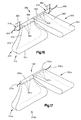
- Fig. 12 illustrates schematically a vehicle occupant safety apparatus 310 for use in a vehicle 312 (Fig. 13).
- the safety apparatus 310 (Fig. 1) includes first and second inflators 314 and 316, described below in more detail.
- the apparatus also includes first and second inflatable vehicle occupant protection devices in the form of a window air bag or side curtain 320 and a headliner air bag 322, both described below in more detail.
- the safety apparatus 310 includes electrical circuitry including a sensor 330 for sensing a vehicle condition such as a side impact to the vehicle 312 or a vehicle rollover condition.
- the safety apparatus 310 also includes a controller 332 for actuating one or both of the inflators 314 and 316 in response to the output of the sensor 330.
- the sensor 330 and the controller 332 cooperate to send an actuation signal to one or both of the inflators 314 and 316 over lead wires 334 and 336.
- the vehicle 312 includes a side structure of which a portion is illustrated at 340.
- the side structure 340 includes a door 342 and a window 344.
- the vehicle also has a roof 346 inside of which is supported a headliner 348.
- a seat 350 is supported on the vehicle floor 352 by tracks 354.
- the seat 350 includes a seat bottom cushion 356 and a seatback 358.
- a vehicle occupant (not shown) sits in the seat 350, the occupant is adjacent to the vehicle door 342 and window 344.
- the side of the occupant's head is adjacent to the window 344.
- the top of the occupant's head is adjacent to the headliner 348.
- the inflators 314 and 316 and the air bags 320 and 322 are mounted as a module 360 in the vehicle 312. As illustrated, the module 360 is mounted at the outboard side of the headliner 348, over the window 344.
- the module 360, or portions thereof including the inflators 314 and 316, may alternatively be mounted near the front of the vehicle 312, on or near the A-pillar, or at another location on the vehicle.
- the module 360 includes means illustrated schematically at 362 (Fig. 16) for mounting the inflators 314 and 316 and the air bags 320 and 322 to the vehicle 312.
- the mounting means 362 is generally of a known construction and therefore is not illustrated in detail.
- the mounting means 362 may include one or more brackets or other fasteners for securing the module 360 in position on the vehicle 312.
- the first air bag 320 when inflated, extends generally downward in the vehicle 312 along the side of the window 344.
- the window air bag 320 has an upper end portion 370 secured to or adjacent the first inflator 314.
- a central portion 372 of the window air bag 320 extends between the window 344 and the occupant's head.
- a lower end portion 374 of the window air bag 320 extends inward of the door 342, at a location below the window 344, so that the inflated air bag can resist movement of the occupant in a direction out of the window opening.
- the first inflator 314 preferably contains a stored quantity of pressurized inflation fluid in the form of gas to inflate the window air bag 320.
- the first inflator alternatively could contain a combination of pressurized inflation fluid and ignitable material for heating the inflation fluid, or could be a pyrotechnic inflator which uses the combustion of gas-generating material to generate inflation fluid.
- the first inflator includes a diffuser 380.
- the diffuser 380 (not shown in detail) is preferably a metal member having a plurality of inflation fluid outlets 382 for directing inflation fluid into the window air bag 320.
- the diffuser 380 may be formed as a portion of the first inflator 314 or may be a separate member connected with or adjacent to the inflator.
- the inflation fluid outlets 382 in the diffuser 380 are oriented in the vehicle 312 so that inflation fluid from the first inflator 314 flows in a predetermined direction into the window air bag 320 to inflate the air bag.
- the inflation fluid outlets 382 are oriented in the vehicle 312 so that inflation fluid from the first inflator 314 flows in a direction to inflate the window air bag 320 between the window 344 and the vehicle occupant's head. This is a vertically downward direction when the vehicle 312 is in an upright orientation.
- the headliner bag 322 has an outer end portion 390 connected with or adjacent to the second inflator 316.
- a main body portion 392 of the headliner bag 322 is extendable between the roof 346 and the headliner 348, at a location above the seat 350 and the occupant's head, so that the inflated headliner bag 322 can help to protect the occupant's head.
- the second inflator 316 is preferably similar in construction to the first inflator 314.
- the second inflator 316 includes a diffuser 400.
- the diffuser 400 (not shown in detail) is preferably a metal member having a plurality of inflation fluid outlets 402 for directing inflation fluid into the headliner bag 322.
- the inflation fluid outlets 402 are oriented in the vehicle 312 so that inflation fluid from the second inflator 316 flows in a predetermined direction into the headliner bag 322 to inflate the headliner bag.
- the inflation fluid outlets 402 are oriented in the vehicle 312 so that inflation fluid from the second inflator 316 is directed generally laterally in the vehicle, to inflate the headliner bag 322 laterally between the roof 346 and the headliner 348, at a location above the seat 350 and the vehicle occupant's head. This is a generally horizontal direction when the vehicle 312 is in an upright orientation.
- the first inflator 314 Upon the occurrence of a vehicle condition, such as a side impact to the vehicle 312, for which it is desired to help protect the occupant of the seat 312, the first inflator 314 is actuated in a known manner by the controller 332. Inflation fluid is directed from the first inflator 314 through the diffuser outlets 382 of the diffuser 380 and into the window air bag 320.
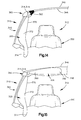
- the window air bag 320 inflates generally vertically downward in the vehicle, between the window 344 and the vehicle occupant's head, as shown in Fig. 14.
- the controller actuates the second inflator 316.
- inflation fluid is directed through the diffuser outlets 402 in the diffuser 400 and into the headliner air bag 322.
- the headliner air bag 322 inflates generally laterally in the vehicle, that is, between the roof 346 and the headliner 348, at a location above the vehicle occupant's head. The interposition of the headliner air bag 322 between the occupant's head and the vehicle roof 346 helps to protect the occupant from injury due to contact with the roof.
- the second inflator 316 is actuated at a selected period of time after the actuation of the first inflator 314. This time delay is provided because a vehicle condition which requires protection of the top of the vehicle occupant's head, that is, a rollover condition, typically develops over a longer period of time than a side impact condition.
- the sensor 330 may comprise separate sensors for sensing a side impact to the vehicle 312 and for sensing a rollover condition of the vehicle.
- Fig. 17 is a schematic fragmentary view of a portion of a vehicle safety apparatus 310a constructed in accordance with a second embodiment of the invention.
- the safety apparatus 310a is similar in construction to the safety apparatus 310 (Figs. 12-16) and similar parts are given the same reference numerals with the suffix "a" added for clarity.
- the safety apparatus 310a includes a single inflator 420 rather than the two separate inflators 314 and 316.
- the inflator 420 (Fig. 17) is a dual stage inflator which includes independently actuatable first and second stages. The first stage of the inflator 420, when actuated, emits inflation fluid under pressure through inflation fluid outlets 382a of a diffuser 380a. The second stage of the inflator 420, when actuated, emits inflation fluid under pressure through inflation fluid outlets 402a of a diffuser 400a.
- the single inflator 420, with the diffusers 380a and 400a is mounted in the vehicle 312 in the same or a similar manner to the mounting of the inflators 314 and 316 as parts of the safety apparatus 310.
- the invention relates to a vehicle occupant safety apparatus for helping to protect an occupant of a vehicle having a roof and a side structure, said apparatus comprising: an inflatable vehicle occupant protection device having a deflated condition and having an inflated condition in which a head portion of said inflatable device is inflated between the top of the occupant's head and the vehicle roof; and an actuatable inflation fluid source for upon actuation directing inflation fluid into said inflatable device to inflate said inflatable device from the deflated condition to the inflated condition.
Abstract
Description
- The present invention relates to a vehicle occupant safety apparatus and, in particular, to a vehicle safety apparatus for helping to protect an occupant of a vehicle having a roof and a side structure
- The present invention is a vehicle occupant safety apparatus for helping to protect an occupant of a vehicle having a roof and a side structure. The apparatus includes an inflatable vehicle occupant protection device having a deflated condition and having an inflated condition in which a head portion of the inflatable device is inflated between the occupant's head and the vehicle roof and a side portion of the inflatable device is inflated between the occupant and the vehicle side structure. The apparatus further includes an actuatable inflation fluid source for, upon actuation, directing inflation fluid into the inflatable device to inflate the inflatable device from the deflated condition to the inflated condition.
- In one embodiment, the head portion of the inflatable device when in the deflated condition has panels which lie generally parallel to a headliner between the headliner and the roof and which extend from the vehicle side approximately to the vehicle centerline. The inflatable device comprises inner and outer panels each made from a single piece of fabric material.
- In another embodiment, an actuatable first inflation fluid source directs inflation fluid into the side portion of the inflatable device. A second inflation fluid source directs inflation fluid into the head portion of the inflatable device. The apparatus further includes control means responsive to at least one sensed vehicle condition for selectively actuating one or both of the fluid sources, with actuation of the second inflation fluid source at a predetermined period of time after actuation of the first inflation fluid source preferred if both fluid sources are actuated.
- The foregoing and other features of the present invention will become apparent to one skilled in the art to which the present invention relates upon consideration of the following description of the invention with reference to the accompanying drawings, wherein:
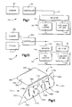
- Fig. 1 is a schematic block diagram of a vehicle occupant safety apparatus in accordance with the present invention including an inflatable vehicle occupant protection device comprising a side curtain and a headliner air bag;
- Fig. 2 is a front elevational view of a portion of a vehicle including the safety apparatus of Fig. 1, the protection device being shown in an uninflated condition;
- Fig. 3 is a perspective view of the protection device shown in an inflated condition;
- Fig. 4 is a plan view of an inner panel which forms one portion of the protection device;
- Fig. 5 is a plan view of an outer panel which forms another portion of the protection device;
- Fig. 6 is a perspective view of the inner and outer panels of the protection device;
- Fig. 7 is an enlarged perspective view showing a portion of the protection device assembled with an inflator;
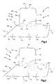
- Fig. 8 is a schematic elevational view of the vehicle showing the protection device in an inflated condition;
- Fig. 9 is a schematic top plan view of the vehicle showing the protection device in an inflated condition;
- Fig. 10 is a view similar to Fig. 1 of a vehicle occupant safety apparatus in accordance with a second embodiment of the present invention;
- Fig. 11 is a view similar to Fig. 3 of a vehicle occupant safety apparatus in accordance with a third embodiment of the present invention;
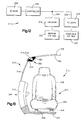
- Fig. 12 is a schematic block diagram of a vehicle occupant safety apparatus embodying the present invention;
- Fig. 13 is a front elevational view of a portion of a vehicle including the safety apparatus of Fig. 12;
- Fig. 14 is a view similar to Fig. 13 of the vehicle occupant safety apparatus including a window air bag shown in an inflated condition;
- Fig. 15 is a view similar to Fig. 14 also showing a headliner air bag in an inflated condition;
- Fig. 16 is a schematic fragmentary view of a portion of the vehicle safety apparatus of Fig. 12; and
- Fig. 17 is a schematic fragmentary view similar to Fig. 16 of a portion of a vehicle safety apparatus constructed in accordance with another embodiment of the invention.
-
- The present invention relates to a vehicle occupant safety apparatus and, in particular, to a vehicle safety apparatus for helping to protect an occupant of a vehicle having a roof and a side structure. The present invention is applicable to various vehicle occupant safety apparatus constructions. As representative of the present invention, Fig. 1 illustrates schematically a vehicle
occupant safety apparatus 10 for use in a vehicle 12 (Fig. 2). - The safety apparatus 10 (Fig. 1) includes an
inflator 14 for inflating an inflatable vehicleoccupant protection device 16. Theprotection device 16 includes a side portion orside curtain 20, and a head portion orheadliner air bag 22, both described below in more detail. - The
inflator 14 preferably contains a stored quantity of pressurized inflation fluid in the form of gas to inflate theprotection device 16. Theinflator 14 alternatively could contain a combination of pressurized inflation fluid and ignitable material for heating the inflation fluid, or could be a pyrotechnic inflator which uses the combustion of gas-generating material to generate inflation fluid. - The
safety apparatus 10 includes asensor 30 for sensing a vehicle condition such as a side impact to thevehicle 12 or a vehicle rollover condition. Thesafety apparatus 10 also includes acontroller 32 for actuating theinflator 14 in response to the output of thesensor 30. Upon the occurrence of a vehicle condition for which inflation of theprotection device 16 is desired to help protect the occupant of thevehicle 12, thesensor 30 and thecontroller 32 cooperate to send an actuation signal to the inflator overlead wires 34. Theinflator 14 is actuated in a manner described below to inflate theprotection device 16. - The
vehicle 12 includes a side structure 40 (Figs. 2 and 8). Thevehicle side structure 40 includes afront door 42 and afront side window 44. Thevehicle side structure 40 also includes aback door 46 and aback side window 48. The vehicle B-pillar 50 is disposed between thefront side window 44 and theback side window 48. Theside structure 40 also includes thevehicle A-pillar 52 and C-pillar 54. - The
vehicle 12 has a roof or roof panel 60 inside of which is supported a headliner 62. The headliner 62 extends generally parallel to the roof panel 60. The roof panel 60 and the headliner 62 both extend laterally in thevehicle 12, from thevehicle side structure 40 past thevehicle centerline 64. - A
front seat 70 of thevehicle 12 is supported on the vehicle floor 72 by tracks 74. Theseat 70 includes a seat bottom cushion 76 and aseatback 78. When a vehicle occupant (shown in Fig. 8 only) sits in theseat 70, the occupant is adjacent to thevehicle front door 42 andwindow 44. The side of the occupant's head is adjacent to thefront side window 44. The top of the occupant's head is adjacent to the headliner 62. Thevehicle 12 also has a back seat 79 (Fig. 8). - The
protection device 16 is made from aninner panel 80 and anouter panel 90. Thepanels panels - The inner panel 80 (Fig. 2) has an inner side surface 82 which is presented toward the headliner and an outer side surface 84 which is presented toward the
outer panel 90. Theinner panel 80 includes a head section 86 (Fig. 4) and aside section 88. - The
outer panel 90 is substantially identical in configuration to theinner panel 80. Theouter panel 90 has an inner side surface 92 (Fig. 2) which is presented toward theinner panel 80 and an outer side surface 94 which is presented toward the roof 60. The outer panel includes a head section 96 (Fig. 5) and aside section 98. - The
head section 86 of the inner panel 80 (Fig. 4) has a generally rectangular configuration including aforward edge portion 100 and arearward edge portion 102. Thehead section 86 also has aninner edge portion 104 and anouter edge portion 106. Theouter edge portion 106 of thehead section 86 merges with theside section 88 of theinner panel 80. - The
side section 88 of theinner panel 80 has an elongate, generally trapezoidal configuration including aforward edge portion 110 and arearward edge portion 112. Theside section 88 of theinner panel 80 also has alower edge portion 114 and anupper edge portion 116. Theupper edge portion 116 of theside section 88 merges with thehead section 86 of theinner panel 80. - The
head section 96 of the outer panel 90 (Fig. 5) has a generally rectangular configuration including aforward edge portion 120 and arearward edge portion 122. Thehead section 96 also has aninner edge portion 124 and anouter edge portion 126. Theouter edge portion 126 of thehead section 96 merges with theside section 98 of the outer panel. - The
side section 98 of theouter panel 90 has an elongate, generally trapezoidal configuration including aforward edge portion 130 and arearward edge portion 132. Theside section 98 of theouter panel 90 also has alower edge portion 134 and anupper edge portion 136. Theupper edge portion 136 of theside section 98 merges with thehead section 96 of the outer panel. - The
inner panel 80 and theouter panel 90 are sewn together along a plurality of sew lines to form theprotection device 16. One sewline 140 extends generally about the outer periphery of thehead sections outer panels line 142 extends generally about the outer periphery of theside sections outer panels lines head sections side sections inflator channel 148 in the inflatable device. (It should be understood that each one of the sew lines in theprotection device 16 may comprise a plurality of individual stitching sections, not merely one.) - The
protection device 16 as thus formed includes theside curtain 20 and theheadliner air bag 22. Theside curtain 20 is made from only theside section 88 of theinner panel 80 and theside section 98 of theouter panel 90. - No other panels are included in the
side curtain 20. Theside curtain 20 includes an inflatable front window segment 150 (Fig. 3) which is defined by the sewlines 142 and additional sewlines line 142 and additional sewlines inflatable pillar segment 162 of theside curtain 20 is defined by the sewline 146 and additional sewlines - The sew lines in the
side portion 20 of theprotection device 16 define three non-inflatable segments 170, 172 and 174 of theside curtain 20. The first or front non-inflatable segment 170 is connected with the vehicle A-pillar 52 and extends between the A-pillar and the inflatablefront window segment 150. The second or middle non-inflatable segment 172 extends between the frontinflatable segment 150 and the back window inflatable segment 156. Theinflatable pillar segment 162 extends partially into the middle non-inflatable segment 172. The third or back non-inflatable segment 174 is connected with the vehicle C-pillar 54 and extends between the inflatable back window segment 156 and the C-pillar. - The
headliner air bag 22 is made from only thehead section 86 of theinner panel 80 and thehead section 96 of theouter panel 90. No other panels are included in theheadliner air bag 22. Theheadliner air bag 22 may optionally include a plurality of tethers 180 (Fig. 6) between thehead section 86 of theinner panel 80 and thehead section 96 of theouter panel 90. Thetethers 180 control the thickness of theheadliner air bag 22 when it is inflated. - The inflator 14 is mounted in the
inflator channel 148 between theheadliner air bag 22 and theside curtain 20. The inflator 14 has a plurality of nozzles or inflation fluid outlets 182 (Fig. 7) for directing inflation fluid into theinflatable device 16 to inflate the inflatable device. - The sew
lines inflator channel 148 are discontinuous to form at least one opening 184 (Figs. 6 and 7) which enables fluid to flow from the inflator 14 into theheadliner air bag 22. The sewlines openings 188 which enable fluid to flow from the inflator 14 into theside curtain 20. - The inflator 14 and the
protection device 16 are mounted as a module 200 in thevehicle 12. As illustrated, the module 200 is mounted at the outboard side of the headliner 62, over thevehicle side structure 40. The module 200, or portions of the module including the inflator 14, may alternatively be mounted near the front of thevehicle 12, on or near the A-pillar 52, or at another location on the vehicle. - The module 200 includes means illustrated schematically at 204 (Fig. 2) for mounting the inflator 14 and the
protection device 16 to thevehicle 12. The mounting means 204 is generally of a known construction and therefore is not illustrated in detail. The mounting means 204 may include one or more brackets or other fasteners for securing the module 200 in position on thevehicle 12. - The upper edge of the front non-inflatable segment 170 of the
side curtain 20 is preferably connected with the A-pillar 52. The upper edge of the back non-inflatable segment 174 of theside curtain 20 is preferably connected with the C-pillar 54. The remainder of theside curtain 20 is stored in a deflated condition above thewindows headliner air bag 22 is disposed in a generally flat condition between the roof panel 60 and the headliner 62. Thehead sections - Upon the occurrence of a vehicle condition for which it is desired to help protect an occupant of the
vehicle 12, such as a side impact to the vehicle or a rollover condition of the vehicle, theinflator 14 is actuated in a known manner by thecontroller 32. Inflation fluid is directed from the inflator 14 through thenozzles 182 of the inflator and into theside curtain 20. Theside curtain 20 inflates generally vertically downward in thevehicle 12, inside theside structure 40 of the vehicle. Inflation fluid flows into theside curtain 20 in the same generally vertically downward direction in the vehicle. - The inflatable
front window segment 150 of theside curtain 20 inflates to a position inside thefront side window 44 of thevehicle 12. The inflatable back window segment 156 of theside curtain 20 inflates to a position inside theback side window 48 of thevehicle 12. - The middle non-inflatable segment 172 of the
side curtain 20 is disposed generally laterally outward of theseatback 78 of thefront seat 70. This enables thefront window segment 150 of the side curtain to inflate laterally inward in thevehicle 12 without being restrained significantly by contact with thefront seatback 78. - The
inflatable pillar segment 162 of theside curtain 20 inflates to a position inside the B-pillar 50 of thevehicle 12. Thepillar segment 162 of theside curtain 20 helps to protect against vehicle occupant contact with the B-pillar 50 of thevehicle 12, and also helps ensure proper inflation of the front and backinflatable segments 150 and 156 of the side curtain. - When the inflator 14 is actuated, inflation fluid is also directed through the
nozzles 182 into theheadliner air bag 22. Theheadliner air bag 22 inflates generally laterally in the vehicle, that is, in a direction transverse to thevehicle side structure 40 and between the roof panel 60 and the headliner 62, at a location above theseat 70. Inflation fluid flows into theheadliner air bag 22 in the same generally lateral direction in the vehicle, transverse to the vehicle side structure. The roof panel 60 is more rigid than the headliner 62, so theheadliner air bag 22 tends to inflate by pushing the headliner toward theseat 70. The interposition of theheadliner air bag 22 between the occupant's head and the vehicle roof 60 helps to protect the occupant from injury due to contact with the roof. Theheadliner air bag 22 may, alternatively, deploy through an opening in the headliner 62, rather than behind the headliner. - Fig. 10 is a view similar to Fig. 1 of a
vehicle safety apparatus 10a constructed in accordance with a second embodiment of the invention. Thesafety apparatus 10a is similar in construction to the safety apparatus 10 (Figs. 1-5) and similar parts are given the same reference numerals with the suffix "a" added for clarity. - The
safety apparatus 10a (Fig. 10) includes twoseparate inflators single inflator 14 of Fig. 1. Theinflator 14a, when actuated, emits inflation fluid under pressure for inflating theside curtain 20a. The inflator 15, when actuated, emits inflation fluid under pressure for inflating theheadliner air bag 22a. Theinflators safety apparatus 10a (Fig. 10) also includes twoseparate sensors 30a and 31, for sensing a side impact condition of the vehicle 12a and a rollover condition of the vehicle, respectively. - A condition of the vehicle 12a which requires protection of the top of the vehicle occupant's head, that is, a rollover condition, typically develops over a longer period of time than a side impact condition. Therefore, the
second inflator 15 may be actuated at a selected period of time after the actuation of thefirst inflator 14a. In addition, it may in some circumstances be desirable to actuate thesecond inflator 15, and thereby inflate theheadliner air bag 22a, prior to (or even without) actuation of thefirst inflator 14a. - Fig. 11 is a view similar to Fig. 3 of a
vehicle safety apparatus 10b constructed in accordance with a third embodiment of the invention. Thesafety apparatus 10b is similar in construction to the safety apparatus 10 (Figs. 1-5) and similar parts are given the same reference numerals with the suffix "b" added for clarity. - The
safety apparatus 10b (Fig. 11) includes aheadliner air bag 22b which extends over both the front seat area and the back seat area of the vehicle 12b. Theheadliner air bag 22b is disposed between a roof panel 60b and a headliner 62b (not shown) of the vehicle 12b. The inflator 14b, when actuated, emits inflation fluid under pressure for inflating theheadliner air bag 22b and theside curtain 20b. The inflatedheadliner air bag 22b can help to protect both front and rear occupants of the vehicle 12b. Thesafety apparatus 10b may, alternatively, include two separate inflators, or separately actuatable stages of a single inflator, as discussed above with reference to the embodiment of Fig. 10. - Fig. 12 illustrates schematically a vehicle
occupant safety apparatus 310 for use in a vehicle 312 (Fig. 13). The safety apparatus 310 (Fig. 1) includes first andsecond inflators side curtain 320 and aheadliner air bag 322, both described below in more detail. - The
safety apparatus 310 includes electrical circuitry including asensor 330 for sensing a vehicle condition such as a side impact to thevehicle 312 or a vehicle rollover condition. Thesafety apparatus 310 also includes acontroller 332 for actuating one or both of theinflators sensor 330. Upon the occurrence of a vehicle condition for which inflation of one or both of theair bags vehicle 312, thesensor 330 and thecontroller 332 cooperate to send an actuation signal to one or both of theinflators lead wires - The
vehicle 312 includes a side structure of which a portion is illustrated at 340. Theside structure 340 includes adoor 342 and awindow 344. The vehicle also has aroof 346 inside of which is supported aheadliner 348. - A
seat 350 is supported on thevehicle floor 352 bytracks 354. Theseat 350 includes aseat bottom cushion 356 and aseatback 358. When a vehicle occupant (not shown) sits in theseat 350, the occupant is adjacent to thevehicle door 342 andwindow 344. The side of the occupant's head is adjacent to thewindow 344. The top of the occupant's head is adjacent to theheadliner 348. - The
inflators air bags module 360 in thevehicle 312. As illustrated, themodule 360 is mounted at the outboard side of theheadliner 348, over thewindow 344. Themodule 360, or portions thereof including theinflators vehicle 312, on or near the A-pillar, or at another location on the vehicle. - The
module 360 includes means illustrated schematically at 362 (Fig. 16) for mounting theinflators air bags vehicle 312. The mounting means 362 is generally of a known construction and therefore is not illustrated in detail. The mounting means 362 may include one or more brackets or other fasteners for securing themodule 360 in position on thevehicle 312. - The
first air bag 320, or window air bag, when inflated, extends generally downward in thevehicle 312 along the side of thewindow 344. Thewindow air bag 320 has anupper end portion 370 secured to or adjacent thefirst inflator 314. Acentral portion 372 of thewindow air bag 320 extends between thewindow 344 and the occupant's head. Alower end portion 374 of thewindow air bag 320 extends inward of thedoor 342, at a location below thewindow 344, so that the inflated air bag can resist movement of the occupant in a direction out of the window opening. - The
first inflator 314 preferably contains a stored quantity of pressurized inflation fluid in the form of gas to inflate thewindow air bag 320. The first inflator alternatively could contain a combination of pressurized inflation fluid and ignitable material for heating the inflation fluid, or could be a pyrotechnic inflator which uses the combustion of gas-generating material to generate inflation fluid. - The first inflator includes a
diffuser 380. The diffuser 380 (not shown in detail) is preferably a metal member having a plurality ofinflation fluid outlets 382 for directing inflation fluid into thewindow air bag 320. Thediffuser 380 may be formed as a portion of thefirst inflator 314 or may be a separate member connected with or adjacent to the inflator. - The
inflation fluid outlets 382 in thediffuser 380 are oriented in thevehicle 312 so that inflation fluid from thefirst inflator 314 flows in a predetermined direction into thewindow air bag 320 to inflate the air bag. Specifically, theinflation fluid outlets 382 are oriented in thevehicle 312 so that inflation fluid from thefirst inflator 314 flows in a direction to inflate thewindow air bag 320 between thewindow 344 and the vehicle occupant's head. This is a vertically downward direction when thevehicle 312 is in an upright orientation. - The
second air bag 322, or headliner bag, when inflated, extends generally laterally in thevehicle 312, between theroof 346 and theheadliner 348. Theheadliner bag 322 has anouter end portion 390 connected with or adjacent to thesecond inflator 316. Amain body portion 392 of theheadliner bag 322 is extendable between theroof 346 and theheadliner 348, at a location above theseat 350 and the occupant's head, so that theinflated headliner bag 322 can help to protect the occupant's head. - The
second inflator 316 is preferably similar in construction to thefirst inflator 314. Thesecond inflator 316 includes adiffuser 400. The diffuser 400 (not shown in detail) is preferably a metal member having a plurality ofinflation fluid outlets 402 for directing inflation fluid into theheadliner bag 322. Theinflation fluid outlets 402 are oriented in thevehicle 312 so that inflation fluid from thesecond inflator 316 flows in a predetermined direction into theheadliner bag 322 to inflate the headliner bag. Specifically, theinflation fluid outlets 402 are oriented in thevehicle 312 so that inflation fluid from thesecond inflator 316 is directed generally laterally in the vehicle, to inflate theheadliner bag 322 laterally between theroof 346 and theheadliner 348, at a location above theseat 350 and the vehicle occupant's head. This is a generally horizontal direction when thevehicle 312 is in an upright orientation. - Upon the occurrence of a vehicle condition, such as a side impact to the
vehicle 312, for which it is desired to help protect the occupant of theseat 312, thefirst inflator 314 is actuated in a known manner by thecontroller 332. Inflation fluid is directed from thefirst inflator 314 through thediffuser outlets 382 of thediffuser 380 and into thewindow air bag 320. Thewindow air bag 320 inflates generally vertically downward in the vehicle, between thewindow 344 and the vehicle occupant's head, as shown in Fig. 14. - If the vehicle electric circuitry, including the
sensor 330 and thecontroller 332, determines that thevehicle 312 may be in a rollover condition, then the controller actuates thesecond inflator 316. When thesecond inflator 316 is actuated, inflation fluid is directed through thediffuser outlets 402 in thediffuser 400 and into theheadliner air bag 322. Theheadliner air bag 322 inflates generally laterally in the vehicle, that is, between theroof 346 and theheadliner 348, at a location above the vehicle occupant's head. The interposition of theheadliner air bag 322 between the occupant's head and thevehicle roof 346 helps to protect the occupant from injury due to contact with the roof. - The
second inflator 316 is actuated at a selected period of time after the actuation of thefirst inflator 314. This time delay is provided because a vehicle condition which requires protection of the top of the vehicle occupant's head, that is, a rollover condition, typically develops over a longer period of time than a side impact condition. - In addition, it may in some circumstances be desirable to actuate the
second inflator 316, and inflate theheadliner air bag 322, prior to (or even without) actuation of thefirst inflator 314. Thus, thesensor 330 may comprise separate sensors for sensing a side impact to thevehicle 312 and for sensing a rollover condition of the vehicle. - Fig. 17 is a schematic fragmentary view of a portion of a
vehicle safety apparatus 310a constructed in accordance with a second embodiment of the invention. Thesafety apparatus 310a is similar in construction to the safety apparatus 310 (Figs. 12-16) and similar parts are given the same reference numerals with the suffix "a" added for clarity. - The
safety apparatus 310a includes asingle inflator 420 rather than the twoseparate inflators inflation fluid outlets 382a of adiffuser 380a. The second stage of the inflator 420, when actuated, emits inflation fluid under pressure throughinflation fluid outlets 402a of adiffuser 400a. Thesingle inflator 420, with thediffusers vehicle 312 in the same or a similar manner to the mounting of theinflators safety apparatus 310. - From the above description of the invention, those skilled in the art will perceive improvements, changes and modifications in the invention. Such improvements, changes and modifications within the skill of the art are intended to be covered by the appended claims.
- According to its broadest aspect the invention relates to a vehicle occupant safety apparatus for helping to protect an occupant of a vehicle having a roof and a side structure, said apparatus comprising: an inflatable vehicle occupant protection device having a deflated condition and having an inflated condition in which a head portion of said inflatable device is inflated between the top of the occupant's head and the vehicle roof; and an actuatable inflation fluid source for upon actuation directing inflation fluid into said inflatable device to inflate said inflatable device from the deflated condition to the inflated condition.
- It should be noted that the objects and advantages of the invention may be attained by means of any compatible combination(s) particularly pointed out in the items of the following summary of the invention and the appended claims.
-
- 1. A vehicle occupant safety apparatus for
helping to protect an occupant of a vehicle having a
roof and a side structure, said apparatus comprising:
- an inflatable vehicle occupant protection device having a deflated condition and having an inflated condition in which a head portion of said inflatable device is inflated between the top of the occupant's head and the vehicle roof and a side portion of said inflatable device is inflated between the occupant and the vehicle side structure; and
- an actuatable inflation fluid source for upon actuation directing inflation fluid into said inflatable device to inflate said inflatable device from the deflated condition to the inflated condition.
- 2. A vehicle occupant safety apparatus wherein said head portion of said inflatable device is inflated by inflation fluid flow in a direction transverse to the vehicle side structure.
- 3. An apparatus wherein said side portion of said inflatable device is inflated by inflation fluid flow in a direction generally parallel to the vehicle side structure.
- 4. An apparatus wherein said inflatable device comprises inner and outer panels each made from a single piece of material.
- 5. An apparatus wherein said head portion of said inflatable device comprises a head section of said inner panel and a head section of said outer panel which lie generally parallel to each other and to the headliner between the headliner and the roof.
- 6. An apparatus wherein
the vehicle has a side structure which includes a front
side window and a back side window, and wherein:
- said side portion of said inflatable device comprises an inflatable front window segment which when inflated extends inside of the front side window of the vehicle and an inflatable back window segment which when inflated extends inside of the back side window of the vehicle;
- said side portion of said inflatable device further comprising at least one non-inflatable segment separating said inflatable front and back window segments of said side portion.
- 7. An apparatus wherein the vehicle has a headliner extending along the inside of the roof, and wherein said head portion of said vehicle occupant protection device when in the deflated condition has panels which lie generally parallel to the headliner between the headliner and the roof and which extend from the vehicle side approximately to the vehicle centerline.
- 8. An apparatus wherein said head portion comprises inner and outer panels each made from a single piece of fabric material.
- 9. An apparatus wherein said head portion further comprises at least one tether for controlling the thickness of said head portion when inflated.
- 10. An apparatus wherein said inflatable vehicle occupant protection device comprises inner and outer panels each made from a single piece of material.
- 11. An apparatus wherein the vehicle has a headliner extending along the inside of the vehicle roof and wherein said head portion of said inflatable device comprises a head section of said inner panel and a head section of said outer panel which lie generally parallel to each other and to the headliner between the headliner and the roof.
- 12. An apparatus wherein the vehicle has a side structure which includes a B-pillar intermediate the front and back side windows, wherein said side portion of said inflatable device further comprises an inflatable pillar segment which extends within said at least one non-inflatable segment and which extends inside the vehicle B-pillar when inflated.
- 13. Apparatus wherein said actuatable inflation fluid source comprises a single inflator.
- 14. A vehicle occupant safety apparatus for
helping to protect an occupant of a vehicle having a
roof and a side structure, said apparatus comprising:
- a first vehicle occupant protection device inflatable into a position between the top of the occupant's head and the vehicle roof;
- an actuatable first inflation fluid source for directing inflation fluid into said first inflatable device to inflate said first inflatable device;
- a second vehicle occupant protection device inflatable into a position between the side of the occupant's head and the vehicle side structure;
- a second inflation fluid source actuatable independently of said first inflation fluid source for directing inflation fluid into said second inflatable device to inflate said second inflatable device; and
- control means responsive to at least one sensed vehicle condition for selectively actuating said second inflation fluid source at a selected time after actuation of said first inflation fluid source.
- 15. Apparatus wherein said control means comprises sensor means for sensing at least one vehicle condition and controller means for selectively providing an inflator actuation signal in response to said sensor means sensing the at least one vehicle condition.
- 16. An apparatus wherein said sensor means is operative to sense a side impact condition of the vehicle and a rollover condition of the vehicle.
- 17. An apparatus wherein said first and second inflation fluid sources comprise first and second stages of a single inflator, said first stage directing inflation fluid into said side portion and said second stage directing inflation fluid into said head portion.
- 18. A vehicle occupant safety apparatus for
helping to protect an occupant of a vehicle having a
roof and a side structure, said apparatus comprising:
- a first vehicle occupant protection device inflatable into a position between the side of the occupant's head and the vehicle side structure;
- a first inflation fluid source for directing inflation fluid into said first inflatable device to inflate said first inflatable device;
- a second vehicle occupant protection device inflatable into a position between the top of the occupant's head and the vehicle roof;
- a second inflation fluid source actuatable independently of said second inflation fluid source for directing inflation fluid into said second inflatable device to inflate said second inflatable device; and
- control means responsive to at least one sensed vehicle condition for selectively actuating one or both of said first and second inflation fluid sources.
- 19. An apparatus wherein said control means comprises sensor means for sensing at least one vehicle condition and controller means for selectively providing an inflator actuation signal in response to said sensor means sensing the at least one vehicle condition.
- 20. An apparatus wherein said sensor means is operative to sense a side impact condition of the vehicle and a rollover condition of the vehicle.
- 21. Apparatus wherein said second vehicle occupant protection device is a headliner bag inflatable into a position between the top of the occupant's head and the vehicle roof and said first vehicle occupant protection device is a window bag inflatable into a position between the side of the occupant's head and the vehicle side structure.
- 22. An apparatus wherein the vehicle includes a headliner supported on the vehicle roof, said headliner air bag being inflatable into a position between the vehicle headliner and the roof of the vehicle.
- 23. An apparatus wherein said first inflation fluid source comprises means for directing inflation fluid to flow from said first inflation fluid source in a generally downward direction in the vehicle to inflate said window air bag in a generally downward direction in the vehicle, and said second inflation fluid source comprises means for directing inflation fluid to flow from said second inflation fluid source in a lateral direction in the vehicle to inflate said headliner air bag in a lateral direction in the vehicle.
-
Claims (10)
- A vehicle occupant safety apparatus for helping to protect an occupant of a vehicle having a roof and a side structure, said apparatus comprising:an inflatable vehicle occupant protection device having a deflated condition and having an inflated condition in which a head portion of said inflatable device is inflated between the top of the occupant's head and the vehicle roof and a side portion of said inflatable device is inflated between the occupant and the vehicle side structure; andan actuatable inflation fluid source for upon actuation directing inflation fluid into said inflatable device to inflate said inflatable device from the deflated condition to the inflated condition.
- A vehicle occupant safety apparatus as defined in claim 1 wherein said head portion of said inflatable device is inflated by inflation fluid flow in a direction transverse to the vehicle side structure.
- An apparatus as set forth in any of the preceding claims wherein said portion of said inflatable device is inflated by inflation fluid flow in a direction generally parallel to the vehicle side structure,and/or wherein preferably said inflatable device comprises inner and outer panels each made from a single piece of material,and/or wherein preferably said head portion of said inflatable device comprises a head section of said inner panel and a head section of said outer panel which lie generally parallel to each other and to the headliner between the headliner and the roof.
- An apparatus as set forth in any of the preceding claims wherein the vehicle has a side structure which includes a front side window and a back side window, and wherein: said side portion of said inflatable device comprises an inflatable front window segment which when inflated extends inside of the front side window of the vehicle and an inflatable back window segment which when inflated extends inside of the back side window of the vehicle;said side portion of said inflatable device further comprising at least one non-inflatable segment separating said inflatable front and back window segments of said side portion,and/or wherein preferably the vehicle has a headliner extending along the inside of the roof, and wherein said head portion of said vehicle occupant protection device when in the deflated condition has panels which lie generally parallel to the headliner between the headliner and the roof and which extend from the vehicle side approximately to the vehicle centerline,and/or wherein preferably said head portion comprises inner and outer panels each made from a single piece of fabric material,and/or wherein preferably said head portion further comprises at least one tether for controlling the thickness of said head portion when inflated.
- An apparatus as defined in any of the preceding claims wherein said inflatable vehicle occupant protection device comprises inner and outer panels each made from a single piece of material,and/or wherein preferably the vehicle has a headliner extending along the inside of the vehicle roof and wherein said head portion of said inflatable device comprises a head section of said inner panel and a head section of said outer panel which lie generally parallel to each other and to the headliner between the headliner and the roof,and/or wherein preferably the vehicle has a side structure which includes a B-pillar intermediate the front and back side windows, wherein said side portion of said inflatable device further comprises an inflatable pillar segment which extends within said at least one non-inflatable segment and which extends inside the vehicle B-pillar when inflated,and/or wherein preferably said actuatable inflation fluid source comprises a single inflator.
- A vehicle occupant safety apparatus for helping to protect an occupant of a vehicle having a roof and a side structure, said apparatus comprising:a first vehicle occupant protection device inflatable into a position between the top of the occupant's head and the vehicle roof;an actuatable first inflation fluid source for directing inflation fluid into said first inflatable device to inflate said first inflatable device;a second vehicle occupant protection device inflatable into a position between the side of the occupant's head and the vehicle side structure;a second inflation fluid source actuatable independently of said first inflation fluid source for directing inflation fluid into said second inflatable device to inflate said second inflatable device; andcontrol means responsive to at least one sensed vehicle condition for selectively actuating said second inflation fluid source at a selected time after actuation of said first inflation fluid source.
- Apparatus as set forth in any of the preceding claims wherein said control means comprises sensor means for sensing at least one vehicle condition and controller means for selectively providing an inflator actuation signal in response to said sensor means sensing the at least one vehicle condition,and/or wherein preferably said sensor means is operative to sense a side impact condition of the vehicle and a rollover condition of the vehicle,and/or wherein preferably said first and second inflation fluid sources comprise first and second stages of a single inflator, said first stage directing inflation fluid into said side portion and said second stage directing inflation fluid into said head portion.
- A vehicle occupant safety apparatus for helping to protect an occupant of a vehicle having a roof and a side structure, said apparatus comprising:a first vehicle occupant protection device inflatable into a position between the side of the occupant's head and the vehicle side structure;a first inflation fluid source for directing inflation fluid into said first inflatable device to inflate said first inflatable device;a second vehicle occupant protection device inflatable into a position between the top of the occupant's head and the vehicle roof;a second inflation fluid source actuatable independently of said second inflation fluid source for directing inflation fluid into said second inflatable device to inflate said second inflatable device; andcontrol means responsive to at least one sensed vehicle condition for selectively actuating one or both of said first and second inflation fluid sources.
- An apparatus as set forth in any of the preceding claims wherein said control means comprises sensor means for sensing at least one vehicle condition and controller means for selectively providing an inflator actuation signal in response to said sensor means sensing the at least one vehicle condition,and/or wherein preferably said sensor means is operative to sense a side impact condition of the vehicle and a rollover condition of the vehicle,and/or wherein preferably said second vehicle occupant protection device is a headliner bag inflatable into a position between the top of the occupant's head and the vehicle roof and said first vehicle occupant protection device is a window bag inflatable into a position between the side of the occupant's head and the vehicle side structure,and/or wherein preferably the vehicle includes a headliner supported on the vehicle roof, said headliner air bag being inflatable into a position between the vehicle headliner and the roof of the vehicle,and/or wherein preferably said first inflation fluid source comprises means for directing inflation fluid to flow from said first inflation fluid source in a generally downward direction in the vehicle to inflate said window air bag in a generally downward direction in the vehicle, and said second inflation fluid source comprises means for directing inflation fluid to flow from said second inflation fluid source in a lateral direction in the vehicle to inflate said headliner air bag in a lateral direction in the vehicle.
- A vehicle occupant safety apparatus for helping to protect an occupant of a vehicle having a roof and a side structure, said apparatus comprising:an inflatable vehicle occupant protection device having a deflated condition and having an inflated condition in which a head portion of said inflatable device is inflated between the top of the occupant's head and the vehicle roof; andan actuatable inflation fluid source for upon actuation directing inflation fluid into said inflatable device to inflate said inflatable device from the deflated condition to the inflated condition.
Applications Claiming Priority (4)
| Application Number | Priority Date | Filing Date | Title |
|---|---|---|---|
| US09/040,857 US6123355A (en) | 1998-03-18 | 1998-03-18 | Vehicle occupant safety apparatus |
| US40857 | 1998-03-18 | ||
| US09/099,707 US6457740B1 (en) | 1998-06-19 | 1998-06-19 | Vehicle occupant safety apparatus |
| US99707 | 1998-06-19 |
Publications (3)
| Publication Number | Publication Date |
|---|---|
| EP0943501A2 true EP0943501A2 (en) | 1999-09-22 |
| EP0943501A3 EP0943501A3 (en) | 2000-02-23 |
| EP0943501B1 EP0943501B1 (en) | 2004-06-02 |
Family
ID=26717524
Family Applications (1)
| Application Number | Title | Priority Date | Filing Date |
|---|---|---|---|
| EP19990105469 Expired - Lifetime EP0943501B1 (en) | 1998-03-18 | 1999-03-17 | Vehicle occupant safety apparatus |
Country Status (3)
| Country | Link |
|---|---|
| EP (1) | EP0943501B1 (en) |
| JP (1) | JP3472506B2 (en) |
| DE (1) | DE69917701T2 (en) |
Cited By (6)
| Publication number | Priority date | Publication date | Assignee | Title |
|---|---|---|---|---|
| DE10039804A1 (en) * | 2000-08-16 | 2002-02-28 | Volkswagen Ag | Vehicle roof has outer shell and lining connected to it by clips, tensioning straps on bodywork being connected by cables to the lining which is released if vehicle turns over to form cushion to protect passengers from impact with roof |
| DE10039802A1 (en) * | 2000-08-16 | 2002-02-28 | Volkswagen Ag | Airbag module for motor vehicles has rollover airbags in space between roof skin and roof lining, lowered into passenger space during rollover accident |
| WO2002024490A1 (en) * | 2000-09-19 | 2002-03-28 | Saab Automobile Ab | Protective arrangement in a motor vehicle |
| GB2482772A (en) * | 2010-08-12 | 2012-02-15 | Gm Global Tech Operations Inc | An airbag with first and second chambers inflated at an angle |
| EP2957467A1 (en) * | 2014-06-19 | 2015-12-23 | Toyota Motor Engineering & Manufacturing North America, Inc. | Curtain airbag for vertical and angular motion of occupant in rollover |
| DE102018216961A1 (en) * | 2018-10-02 | 2020-04-02 | Volkswagen Aktiengesellschaft | Occupant protection device for a motor vehicle and motor vehicle |
Families Citing this family (19)
| Publication number | Priority date | Publication date | Assignee | Title |
|---|---|---|---|---|
| DE10007343B4 (en) * | 2000-02-18 | 2010-07-22 | Volkswagen Ag | Safety device for the occupants of a vehicle, in particular for a motor vehicle |
| US6705640B2 (en) | 2000-08-28 | 2004-03-16 | Toyota Jidosha Kabushiki Kaisha | Head-protection airbag device |
| JP3584903B2 (en) | 2000-12-27 | 2004-11-04 | トヨタ自動車株式会社 | Head protection airbag device |
| US7364185B2 (en) | 2002-07-29 | 2008-04-29 | Toyoda Gosei Co., Ltd. | Occupant protecting device and air bag device for rear-end collision mounted on vehicle |
| JP3951907B2 (en) * | 2002-12-05 | 2007-08-01 | 豊田合成株式会社 | Airbag device |
| JP4244655B2 (en) * | 2003-02-20 | 2009-03-25 | 日産自動車株式会社 | Crew restraint system |
| DE102004023853A1 (en) | 2003-05-14 | 2005-01-20 | Toyoda Gosei Co., Ltd., Nishikasugai | A folding method for an airbag for a rear-end collision and an air-bag device for a rear-end collision |
| DE102005014087A1 (en) * | 2005-03-22 | 2006-10-19 | Takata-Petri (Ulm) Gmbh | Headliner module and method for mounting an airbag module in a motor vehicle |
| JP4876663B2 (en) * | 2005-03-31 | 2012-02-15 | 日産自動車株式会社 | Occupant protection device during vehicle rollover |
| DE202006005317U1 (en) * | 2006-03-27 | 2006-06-14 | Takata-Petri (Ulm) Gmbh | Airbag assembly for a vehicle occupant restraint device |
| JP4882459B2 (en) * | 2006-04-03 | 2012-02-22 | 日産自動車株式会社 | Vehicle occupant protection methods |
| JP4221017B2 (en) * | 2006-08-31 | 2009-02-12 | トヨタ自動車株式会社 | Head protection airbag device |
| DE102007017998A1 (en) | 2007-04-13 | 2008-10-16 | Keiper Gmbh & Co.Kg | Protection device arrangement for motor vehicle, has unfolded energy absorber arranged in luggage compartment of motor vehicle behind backrest of seat, and damping impact of loaded goods on seat and backrest |
| JP2009056858A (en) * | 2007-08-30 | 2009-03-19 | Kanto Auto Works Ltd | Air bag device for automobile |
| JP5435913B2 (en) * | 2008-08-29 | 2014-03-05 | 日本プラスト株式会社 | Airbag device |
| JP5414089B2 (en) * | 2008-08-29 | 2014-02-12 | 日本プラスト株式会社 | Airbag device |
| JP2012062043A (en) * | 2010-08-20 | 2012-03-29 | Autoliv Development Ab | Safety device |
| KR101241157B1 (en) * | 2010-11-29 | 2013-03-11 | 현대자동차주식회사 | Intternal air bag device |
| KR102623126B1 (en) * | 2019-01-15 | 2024-01-10 | 현대모비스 주식회사 | Looftop airbag apparatus |
Family Cites Families (4)
| Publication number | Priority date | Publication date | Assignee | Title |
|---|---|---|---|---|
| JP3107383B2 (en) * | 1990-03-26 | 2000-11-06 | マツダ株式会社 | Energy absorption structure on the side of the vehicle |
| US5775726A (en) * | 1996-05-29 | 1998-07-07 | Morton International, Inc. | Roof-mounted air bag |
| DE19632222B4 (en) * | 1996-08-09 | 2005-03-31 | Müller, Olaf | Interior trim for a vehicle roof |
| DE19650940A1 (en) * | 1996-12-07 | 1998-06-10 | Bayerische Motoren Werke Ag | Side impact protection in road vehicle |
-
1999
- 1999-03-17 EP EP19990105469 patent/EP0943501B1/en not_active Expired - Lifetime
- 1999-03-17 JP JP07186399A patent/JP3472506B2/en not_active Expired - Fee Related
- 1999-03-17 DE DE1999617701 patent/DE69917701T2/en not_active Expired - Lifetime
Non-Patent Citations (1)
| Title |
|---|
| None |
Cited By (8)
| Publication number | Priority date | Publication date | Assignee | Title |
|---|---|---|---|---|
| DE10039804A1 (en) * | 2000-08-16 | 2002-02-28 | Volkswagen Ag | Vehicle roof has outer shell and lining connected to it by clips, tensioning straps on bodywork being connected by cables to the lining which is released if vehicle turns over to form cushion to protect passengers from impact with roof |
| DE10039802A1 (en) * | 2000-08-16 | 2002-02-28 | Volkswagen Ag | Airbag module for motor vehicles has rollover airbags in space between roof skin and roof lining, lowered into passenger space during rollover accident |
| DE10039802B4 (en) * | 2000-08-16 | 2013-07-04 | Volkswagen Ag | Safety device for the occupants of a vehicle, in particular of a motor vehicle |
| WO2002024490A1 (en) * | 2000-09-19 | 2002-03-28 | Saab Automobile Ab | Protective arrangement in a motor vehicle |
| GB2482772A (en) * | 2010-08-12 | 2012-02-15 | Gm Global Tech Operations Inc | An airbag with first and second chambers inflated at an angle |
| EP2957467A1 (en) * | 2014-06-19 | 2015-12-23 | Toyota Motor Engineering & Manufacturing North America, Inc. | Curtain airbag for vertical and angular motion of occupant in rollover |
| DE102018216961A1 (en) * | 2018-10-02 | 2020-04-02 | Volkswagen Aktiengesellschaft | Occupant protection device for a motor vehicle and motor vehicle |
| US10940823B2 (en) | 2018-10-02 | 2021-03-09 | Volkswagen Aktiengesellschaft | Occupant protection device for a motor vehicle and motor vehicle |
Also Published As
| Publication number | Publication date |
|---|---|
| DE69917701T2 (en) | 2005-07-21 |
| JP3472506B2 (en) | 2003-12-02 |
| JPH11321538A (en) | 1999-11-24 |
| EP0943501A3 (en) | 2000-02-23 |
| EP0943501B1 (en) | 2004-06-02 |
| DE69917701D1 (en) | 2004-07-08 |
Similar Documents
| Publication | Publication Date | Title |
|---|---|---|
| US6457740B1 (en) | Vehicle occupant safety apparatus | |
| EP0943501B1 (en) | Vehicle occupant safety apparatus | |
| US6123355A (en) | Vehicle occupant safety apparatus | |
| US6273458B1 (en) | Inflatable curtain | |
| US6176515B1 (en) | Inflatable curtain with positioning device | |
| US6237941B1 (en) | Inflatable side airbag curtain module | |
| US6471240B2 (en) | Inflatable side curtain | |
| US6364349B1 (en) | Inflatable curtain housing with deployment flap | |
| EP1364841B1 (en) | Occupant protection device | |
| US5913536A (en) | Air bag module | |
| US6237939B1 (en) | Inflatable curtain | |
| US6361068B1 (en) | Folded inflatable side curtain with tether | |
| US6464250B1 (en) | Inflatable curtain with slidable tether | |
| US6095551A (en) | Non-inflatable curtain with inflatable device | |
| US6565118B2 (en) | Folded inflatable curtain | |
| US6467563B1 (en) | Windshield frame air bag for pedestrian protection | |
| US6409211B1 (en) | Inflatable side curtain | |
| US6695341B2 (en) | Containment impact protection system | |
| US7017942B2 (en) | Inflatable vehicle occupant protection device with grab handle | |
| US6116644A (en) | Frontal air bag system | |
| GB2272670A (en) | Vehicle door with pre-deployed air bag. | |
| US20070126217A1 (en) | Front and side impact air bag arrangements | |
| US6428037B1 (en) | Inflatable curtain | |
| US6231073B1 (en) | Inflatable side curtain | |
| US7000945B2 (en) | Inflatable windshield curtain |
Legal Events
| Date | Code | Title | Description |
|---|---|---|---|
| PUAI | Public reference made under article 153(3) epc to a published international application that has entered the european phase |
Free format text: ORIGINAL CODE: 0009012 |
|
| AK | Designated contracting states |
Kind code of ref document: A2 Designated state(s): DE FR GB IT |
|
| AX | Request for extension of the european patent |
Free format text: AL;LT;LV;MK;RO;SI |
|
| PUAL | Search report despatched |
Free format text: ORIGINAL CODE: 0009013 |
|
| AK | Designated contracting states |
Kind code of ref document: A3 Designated state(s): AT BE CH CY DE DK ES FI FR GB GR IE IT LI LU MC NL PT SE |
|
| AX | Request for extension of the european patent |
Free format text: AL;LT;LV;MK;RO;SI |
|
| RIC1 | Information provided on ipc code assigned before grant |
Free format text: 7B 60R 21/22 A, 7B 60R 21/24 B, 7B 60R 21/16 B |
|
| 17P | Request for examination filed |
Effective date: 20000822 |
|
| AKX | Designation fees paid |
Free format text: DE FR GB IT |
|
| 17Q | First examination report despatched |
Effective date: 20020603 |
|
| GRAP | Despatch of communication of intention to grant a patent |
Free format text: ORIGINAL CODE: EPIDOSNIGR1 |
|
| GRAS | Grant fee paid |
Free format text: ORIGINAL CODE: EPIDOSNIGR3 |
|
| GRAA | (expected) grant |
Free format text: ORIGINAL CODE: 0009210 |
|
| AK | Designated contracting states |
Kind code of ref document: B1 Designated state(s): DE FR GB IT |
|
| PG25 | Lapsed in a contracting state [announced via postgrant information from national office to epo] |
Ref country code: IT Free format text: LAPSE BECAUSE OF FAILURE TO SUBMIT A TRANSLATION OF THE DESCRIPTION OR TO PAY THE FEE WITHIN THE PRESCRIBED TIME-LIMIT;WARNING: LAPSES OF ITALIAN PATENTS WITH EFFECTIVE DATE BEFORE 2007 MAY HAVE OCCURRED AT ANY TIME BEFORE 2007. THE CORRECT EFFECTIVE DATE MAY BE DIFFERENT FROM THE ONE RECORDED. Effective date: 20040602 Ref country code: FR Free format text: LAPSE BECAUSE OF FAILURE TO SUBMIT A TRANSLATION OF THE DESCRIPTION OR TO PAY THE FEE WITHIN THE PRESCRIBED TIME-LIMIT Effective date: 20040602 |
|
| REG | Reference to a national code |
Ref country code: GB Ref legal event code: FG4D |
|
| REF | Corresponds to: |
Ref document number: 69917701 Country of ref document: DE Date of ref document: 20040708 Kind code of ref document: P |
|
| PG25 | Lapsed in a contracting state [announced via postgrant information from national office to epo] |
Ref country code: GB Free format text: LAPSE BECAUSE OF NON-PAYMENT OF DUE FEES Effective date: 20050317 |
|
| PLBE | No opposition filed within time limit |
Free format text: ORIGINAL CODE: 0009261 |
|
| STAA | Information on the status of an ep patent application or granted ep patent |
Free format text: STATUS: NO OPPOSITION FILED WITHIN TIME LIMIT |
|
| 26N | No opposition filed |
Effective date: 20050303 |
|
| EN | Fr: translation not filed | ||
| GBPC | Gb: european patent ceased through non-payment of renewal fee |
Effective date: 20050317 |
|
| PGFP | Annual fee paid to national office [announced via postgrant information from national office to epo] |
Ref country code: DE Payment date: 20150331 Year of fee payment: 17 |
|
| REG | Reference to a national code |
Ref country code: DE Ref legal event code: R119 Ref document number: 69917701 Country of ref document: DE |
|
| PG25 | Lapsed in a contracting state [announced via postgrant information from national office to epo] |
Ref country code: DE Free format text: LAPSE BECAUSE OF NON-PAYMENT OF DUE FEES Effective date: 20161001 |