EP0943373B1 - Verfahren zur Reparatur kleiner Lackfehler bei Pulverlackschichten - Google Patents
Verfahren zur Reparatur kleiner Lackfehler bei Pulverlackschichten Download PDFInfo
- Publication number
- EP0943373B1 EP0943373B1 EP99104226A EP99104226A EP0943373B1 EP 0943373 B1 EP0943373 B1 EP 0943373B1 EP 99104226 A EP99104226 A EP 99104226A EP 99104226 A EP99104226 A EP 99104226A EP 0943373 B1 EP0943373 B1 EP 0943373B1
- Authority
- EP
- European Patent Office
- Prior art keywords
- recess
- filler body
- packing
- filler
- powder coating
- Prior art date
- Legal status (The legal status is an assumption and is not a legal conclusion. Google has not performed a legal analysis and makes no representation as to the accuracy of the status listed.)
- Expired - Lifetime
Links
- 239000000843 powder Substances 0.000 title claims description 48
- 238000000034 method Methods 0.000 title claims description 16
- 230000007547 defect Effects 0.000 title claims description 9
- 238000000576 coating method Methods 0.000 title description 15
- 239000000945 filler Substances 0.000 claims description 36
- 230000008439 repair process Effects 0.000 claims description 10
- 239000003973 paint Substances 0.000 claims description 8
- 238000004140 cleaning Methods 0.000 claims 1
- 239000007788 liquid Substances 0.000 claims 1
- 238000006386 neutralization reaction Methods 0.000 claims 1
- 238000012856 packing Methods 0.000 description 36
- 239000011247 coating layer Substances 0.000 description 25
- 239000010410 layer Substances 0.000 description 12
- 238000003801 milling Methods 0.000 description 12
- 239000011248 coating agent Substances 0.000 description 10
- 239000000463 material Substances 0.000 description 9
- 239000004922 lacquer Substances 0.000 description 8
- 238000003754 machining Methods 0.000 description 7
- 230000005855 radiation Effects 0.000 description 5
- 239000012790 adhesive layer Substances 0.000 description 4
- 239000012634 fragment Substances 0.000 description 4
- 229910052736 halogen Inorganic materials 0.000 description 4
- 150000002367 halogens Chemical class 0.000 description 4
- 239000000758 substrate Substances 0.000 description 4
- 239000000428 dust Substances 0.000 description 3
- 239000011148 porous material Substances 0.000 description 3
- 230000001427 coherent effect Effects 0.000 description 2
- 238000010438 heat treatment Methods 0.000 description 2
- 239000002184 metal Substances 0.000 description 2
- 239000002105 nanoparticle Substances 0.000 description 2
- 239000002243 precursor Substances 0.000 description 2
- 101100117236 Drosophila melanogaster speck gene Proteins 0.000 description 1
- 229920002430 Fibre-reinforced plastic Polymers 0.000 description 1
- 239000006096 absorbing agent Substances 0.000 description 1
- 230000009471 action Effects 0.000 description 1
- 230000002411 adverse Effects 0.000 description 1
- 230000008901 benefit Effects 0.000 description 1
- 230000008859 change Effects 0.000 description 1
- 238000005553 drilling Methods 0.000 description 1
- 230000000694 effects Effects 0.000 description 1
- 230000005611 electricity Effects 0.000 description 1
- 230000005670 electromagnetic radiation Effects 0.000 description 1
- 238000007590 electrostatic spraying Methods 0.000 description 1
- 230000002349 favourable effect Effects 0.000 description 1
- 239000011151 fibre-reinforced plastic Substances 0.000 description 1
- 239000011521 glass Substances 0.000 description 1
- 230000006872 improvement Effects 0.000 description 1
- 238000003780 insertion Methods 0.000 description 1
- 230000037431 insertion Effects 0.000 description 1
- 239000012229 microporous material Substances 0.000 description 1
- 230000007935 neutral effect Effects 0.000 description 1
- 238000010943 off-gassing Methods 0.000 description 1
- 230000003287 optical effect Effects 0.000 description 1
- 239000004033 plastic Substances 0.000 description 1
- 229920003023 plastic Polymers 0.000 description 1
- 238000004080 punching Methods 0.000 description 1
- 230000035939 shock Effects 0.000 description 1
- 230000003068 static effect Effects 0.000 description 1
- 230000007704 transition Effects 0.000 description 1
Images


Classifications
-
- B—PERFORMING OPERATIONS; TRANSPORTING
- B05—SPRAYING OR ATOMISING IN GENERAL; APPLYING FLUENT MATERIALS TO SURFACES, IN GENERAL
- B05D—PROCESSES FOR APPLYING FLUENT MATERIALS TO SURFACES, IN GENERAL
- B05D5/00—Processes for applying liquids or other fluent materials to surfaces to obtain special surface effects, finishes or structures
- B05D5/005—Repairing damaged coatings
Definitions
- the invention relates to a method and an apparatus for Repair of small paint defects in powder coatings according to the Preamble of claim 1 as it is based on the generic laid out DE 196 46 956.2 emerges as known.
- the object of the invention is the underlying repair method to improve that the repair of Powder coating layers with a packing is simplified.
- the object is achieved in a method with the Process steps of claim 1 solved.
- Through the electrical Discharge of the recess and the electrical charge of the Packing is the packing without further action in the Recess at least until the filler body cures supported.
- Figure 1 is a section of a curved powder coating 1 of a substrate.
- the substrate can, for example, be made of metal, Plastic and / or fiber reinforced plastic, MDF material and / or similar powder-coated materials his.
- the powder coating layer 1 can despite various precautionary errors such as for example enclosed dust grains occur. To repair one faulty location, this will be within a very limited framework the hardened powder coating in particular 1 provided with a recess 2, which in the present embodiment is cylindrical.
- the faulty Blown in place with ionized air which makes the milling occurring static electricity is electrically neutralized and ideally the cutout to an electrical zero potential brought, i.e. is discharged electrically. simultaneously through the preferably dried air, the recess 2 also cleaned.
- the layer thickness of a film from which the Filler 3 is manufactured in particular to be punched. It is sensible to measure the layer thickness of the film at the point where the packing 3 is punched out of the film shall be.
- the packing is advantageously 3 at the same time electrically charged when punching, which makes it in the electrically neutral recess 2 without further measures can be introduced by adhesion.
- the error for example, eliminates the speck of dust.
- the recess 2 is advantageously machined and here in particular by means of asymmetrical milling - i.e. the cutting edges of the milling cutter do not run through the center the milling surface - or sanding into the powder coating 1 introduced.
- the recess 2 can also be drilled and / or sawn holes and / or burned out by laser and / or are punched out and / or ground.
- Introduction of the recess 2 in the powder coating layer 1 is make sure that the recess 2 with respect to its area, or width and also with regard to their depth with exactly defined dimensions and with a given edge contour is introduced into the powder coating layer 1.
- the one which is at least partially crosslinked before being introduced into the recess 2 Packing body 3 corresponds to the volume of the recess 2 dimensioned and coherent in the sense of a monolith; i.e. the diameter of the monolithically related Packing body 3 corresponds approximately to the width of the recess 2 and the layer thickness of the packing 3 is approximately the depth of the Recess.
- this exact dimensioning in can be realized in a simple manner in that the filler body 3 molded from a previously made paint film, in particular is punched out. With at least some effect powder coatings this lacquer film is used to obtain the desired optical properties expediently by electrostatic spraying manufactured.
- a pressure body 4 is created, which is expedient protrudes beyond the edges of the recess 2 and further conveniently flat to the edges of the recess 2 on the Visible side 5 of the powder coating layer 1 is applied.
- the filler 3 is the outside of the recess 2 arranged powder coating layer 1 connected.
- connection is preferably made by a adhesive Layer "adhesive layer” (not shown) either on the packing 3 or even before the packing is introduced 3 in the recess 2 along the corresponding walls of the Packing 3 is arranged.
- the filler introduced into the recess 2 3 and possibly also the "adhesive layer" heated and / or for Brought reaction.
- the packing 3 By heating and / or by reaction hardens in particular the packing 3 and possibly also the Adhesive layer.
- a pressure on the filler body 3 exercised. Since the surface of the Pressure body 4 - ie the contact surface 6 - expediently is as smooth as possible, results from this pressure also a good surface of the hardened packing 3.
- the reaction is preferably carried out by UV radiation and / or electromagnetic, especially IR radiation, and / or hotter Air introduced and / or maintained.
- electromagnetic radiation especially IR radiation, and / or hotter Air introduced and / or maintained.
- the pressure body 4 expediently in the area has its contact surface 6 on the packing 3 pores, through which the resulting gas is discharged.
- the contact surface 6, in a special version also the entire pressure body 4 made of so-called nanoparticles be made.
- the connection of the filling element 3 and / or the curing of the packing 3 by means of electromagnetic, initiated IR radiation in particular, it is expedient the size of the nanoparticles is smaller than the wavelength to choose the radiation in question.
- filler 3 depending on the material used during curing can have a volume shrinkage, it is also favorable to Filling body 3 to be provided with a volume that is approximately the volume the recess 2 plus that which occurs during hardening Volume shrinkage of the packing 3 corresponds.
- a powder coating layer 1 is shown in the area a faulty place of the particularly tied and hardened powder coating layer 1 with a truncated cone Recess 2 is provided.
- the cone of the recess 2 joins the substrate.
- the cutout 2 introduced into the powder coating layer 1 becomes simultaneous the error, for example a grain of dust, is eliminated.
- the frustoconical recess 2 is included arranged packing 3 and arranged above the packing 3 Repair device shown.
- the packing 3 is made of powder coating and / or a precursor of the powder coating manufactured and shaped in particular plate-like.
- the edges of the packing 3 are in terms of their geometric dimensions and also with regard to their course, for example when they are introduced the recess 2 is not necessarily round, but may also be kidney-shaped, for example, the edges of the recess 2 adjusted.
- the filler 3 is ejected from the covering lacquer film and inserted directly into the recess 2 when ejecting and / or indented.
- the packing 3 arranged in the recess 2 is connected to the powder coating layer 1 arranged outside the recess 2 connected by the measures listed above.
- the connection takes place through a direct connection of the material of the packing 3 with the surrounding material of the powder coating layer 1.
- the connection of the filler 3 with the powder coating layer 1 does not have to run along the entire common area but can be done on individual common sub-areas be limited. In the case of fillers formed from fragments 8 3 at the same time the fragments 8 in the same Way connected.
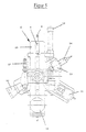
- Figures 5 and 6 is a device 9 for repair defects in powder coating layers under supervision and shown in a side view.
- the device 9 has a rotatably supported one Base plate on, for example, via a rotary stepper motor 18 an arm of an industrial robot (not shown) can be.
- the industrial robot is a sensible one Cartesian portal robot, so that it is as precise as possible Control is possible.
- the individual processing tools are on the base plate 10 arranged in a star shape for the various work steps.
- the axes of the machining tools are at right angles to the use the axis of rotation of the base plate and parallel to the surface orthogonal the powder coating layer 1 aligned in the region of the recess 2.
- the axis of rotation of the base plate 10 itself is transverse to the surface orthogonal the powder coating layer 1 in the area of the recess 2 aligned.
- the processing tools like the lenses of a microscope with different lenses arranged in the beam path be, the editing tools with the lenses and the rotating plate of the microscope that supports the lenses the base plate 10 is comparable.
- the processing tools are in the device 9 according to FIGS. 5 and 6 mounted on the flat base plate 10.
- the Base plate 10 is by means of the rotary stepping motor 11, the Axis of rotation aligned orthogonally to the flat side of the base plate 10 is rotatably supported.
- the machining tools are star-shaped and with their machining axis parallel to the flat side of the base plate 10 on the Base plate 10 arranged.
- the processing tools it is in detail a milling headstock 11, a Dial gauge 12, a micrometer 13, a punch 14, a Vacuum holder 15, a halogen lamp 16 and the preferably heatable Pressure element 4 with a flat contact surface 6.
- the machining tools can be rotated via the base plate 10 and linearly displaceable in the direction of the pivot axis of the base plate 10
- the machining tools can be rotated via the base plate 10 and linearly displaceable in the direction of the pivot axis of the base plate 10
- a robot arm (not shown). This arrangement allows the respective processing tool with its machining axis in a simple way high precision perpendicular to the surface of the powder coating layer 1 be positioned in the area of the faulty location.
- the ball-bearing in the milling headstock 11 and one speed-controlled motor 17 driven milling spindle 18 is with a pneumatic cylinder 19 on the surface of the powder coating layer 1 roughly lowered and with the micrometer screw 13 adjusted so that the surface in the area of the faulty Spot is just touched.
- the zero point thus obtained is recorded with the dial gauge 12 and set the required milling depth with the micrometer 13.
- the milling spindle lowers to the previously set one Milling or drilling depth.
- the recess becomes during milling 2 permanently blown out with preferably ionized air. This means that it is electrically discharged, dust-free and light cooled.
- the finished recess 2 is also after the completion of the milling process even more with ionized Air blown, taking the recess during this time irradiated with the halogen lamp 16 and preferably to about 50 ° C is heated.
- the halogen lamp 16 is used except for heating the recess 2 is also used to illuminate the workpiece.
- the filler 3 to be inserted into the recess 2 is included the punch 14 punched out of the film.
- the punched out Packing 3 is held with the vacuum holder 15 and the base plate 10 back into the working position above the recess 2 brought. After lowering with the cylinder 19 the filler 3 exactly over a seated in the punch 14 Piston fitted in the recess 2.
- the filler 3 is then heated with the pressure body 4 pressed and to a maximum of 110 ° C (depending on the type of Powder) heated.
- the packing is 3 after about 1 - 4 min so that it fixes with the halogen lamp 16 at approx. 175 ° C (depending on the type of powder) within cured for about 15 minutes (depending on the type of powder) can be.
Landscapes
- Application Of Or Painting With Fluid Materials (AREA)
- Electrostatic Spraying Apparatus (AREA)
- Prevention Of Fouling (AREA)
Description
- Fig. 1
- einen Ausschnitt eines Schnittes durch eine Pulverlackschicht mit im Bereich einer Fehlerstelle eingebrachter zylindrischer Aussparung,
- Fig. 2
- den Ausschnitt nach Figur 1 mit in der Aussparung angeordnetem Füllkörper,
- Fig. 3
- einen Ausschnitt eines Schnittes durch eine mit einer Klarlackschicht bedeckten Pulverlackschicht mit kegelstumpfförmiger Aussparung,
- Fig. 4
- den Ausschnitt nach Figur 3 mit in der Aussparung angeordnetem Füllkörper,
- Fig. 5
- eine Aufsicht auf eine Vorrichtung zur Reparatur kleiner Lackfehler bei Pulverlackschichten und
- Fig. 6
- eine Seitenansicht der Vorrichtung nach Figur 5.
Claims (9)
- Verfahren zur Reparatur kleiner Lackfehler bei Pulverlackschichten, bei dem der Lackfehler ausgespart, in die Aussparung ein an die Aussparung form- und/oder volumenangepaßten Füllkörper eingebracht, der Füllkörper mit der die Aussparung umgebenden Pulverlackschicht verbunden und ausgehärtet wird,
dadurch gekennzeichnet , daß der Füllkörper vor dem Einsetzen in die Aussparung auf ein elektrisches Potential geladen wird, das sich von dem der Aussparung unterscheidet, und
daß der elektrisch geladene Füllkörper in die elektrisch unterschiedlich geladene Aussparung eingebracht wird. - Verfahren nach Anspruch 1,
dadurch gekennzeichnet, daß die Aussparung zumindest weitgehend und insbesondere auf Null-Potential elektrisch entladen wird, und daß der elektrisch geladene Füllkörper in die zumindest weitgehend entladene Aussparung eingebracht wird. - Verfahren nach Anspruch 1,
dadurch gekennzeichnet, daß die Aussparung vor dem Einbringen des Füllkörpers gereinigt wird. - Verfahren nach Anspruch 1,
dadurch gekennzeichnet, daß die Aussparung vor dem Einbringen des Füllkörpers gereinigt wird und daß die elektrische Neutralisation mit dem Reinigen der Aussparung erfolgt. - Verfahren nach Anspruch 1,
dadurch gekennzeichnet, daß die Aussparung mit einem ionisierten Gas, insbesondere mit Luft ausgeblasen wird. - Verfahren nach Anspruch 1,
dadurch gekennzeichnet, daß beim Einbringen der Aussparung der Bereich der späteren Aussparung mit einem ionisierten Gas, insbesondere mit Luft angeblasen wird. - verfahren nach Anspruch 1,
dadurch gekennzeichnet, daß die Aussparung mit einem ionisierten Gas, insbesondere mit Luft ausgeblasen wird und daß dem Gas vor und/oder beim Ionisieren Flüssigkeit entzogen wird. - Verfahren nach Anspruch 1,
dadurch gekennzeichnet, daß der Füllkörper aus einer Folie gefertigt wird, daß vor der Herstellung des Füllkörpers die Dicke der Folie am Ort des späteren Füllkörpers gemessen wird und daß die Aussparung mit einer der Dicke der Folie entsprechenden Tiefe in die Pulverlackschicht eingebracht wird. - Verfahren nach Anspruch 1,
dadurch gekennzeichnet, daß der Füllkörper aus einer Folie ausgestanzt wird.
Applications Claiming Priority (2)
| Application Number | Priority Date | Filing Date | Title |
|---|---|---|---|
| DE19812235A DE19812235C2 (de) | 1998-03-20 | 1998-03-20 | Verfahren zur Reparatur kleiner Lackfehler bei Pulverlackschichten |
| DE19812235 | 1998-03-20 |
Publications (2)
| Publication Number | Publication Date |
|---|---|
| EP0943373A1 EP0943373A1 (de) | 1999-09-22 |
| EP0943373B1 true EP0943373B1 (de) | 2002-09-04 |
Family
ID=7861646
Family Applications (1)
| Application Number | Title | Priority Date | Filing Date |
|---|---|---|---|
| EP99104226A Expired - Lifetime EP0943373B1 (de) | 1998-03-20 | 1999-03-03 | Verfahren zur Reparatur kleiner Lackfehler bei Pulverlackschichten |
Country Status (3)
| Country | Link |
|---|---|
| EP (1) | EP0943373B1 (de) |
| DE (2) | DE19812235C2 (de) |
| ES (1) | ES2182416T3 (de) |
Family Cites Families (3)
| Publication number | Priority date | Publication date | Assignee | Title |
|---|---|---|---|---|
| US4960611A (en) * | 1987-09-30 | 1990-10-02 | Kansai Paint Company, Limited | Method of remedying coating |
| DE19646956C1 (de) * | 1996-11-13 | 1998-05-20 | Daimler Benz Ag | Verfahren zur Reparatur kleiner Lackfehler in Lackschichten |
| DE19727324C1 (de) * | 1997-06-27 | 1999-04-01 | Daimler Benz Ag | Verfahren und Vorrichtung zur Reparatur kleiner Lackfehler in Lackschichten |
-
1998
- 1998-03-20 DE DE19812235A patent/DE19812235C2/de not_active Expired - Fee Related
-
1999
- 1999-03-03 ES ES99104226T patent/ES2182416T3/es not_active Expired - Lifetime
- 1999-03-03 EP EP99104226A patent/EP0943373B1/de not_active Expired - Lifetime
- 1999-03-03 DE DE59902513T patent/DE59902513D1/de not_active Expired - Fee Related
Also Published As
| Publication number | Publication date |
|---|---|
| DE19812235C2 (de) | 2002-06-20 |
| DE19812235A1 (de) | 1999-09-30 |
| DE59902513D1 (de) | 2002-10-10 |
| EP0943373A1 (de) | 1999-09-22 |
| ES2182416T3 (es) | 2003-03-01 |
Similar Documents
| Publication | Publication Date | Title |
|---|---|---|
| DE69323092T2 (de) | Methode und werkzeug zum herstellen von löchern in fiberverstärkten kompositen durch exzentrische bewegung des werkzeugs | |
| EP1430983B1 (de) | Verfahren zur Formgebung durch elektrochemisches Abtragen | |
| DE10157647C5 (de) | Verfahren zur Herstellung von dreidimensionalen Werkstücken in einer Laser-Materialbearbeitungsanlage oder einer Stereolitographieanlage | |
| EP0842710B1 (de) | Verfahren zur Reparatur kleiner Lackfehler in Lackschichten | |
| EP3360640B1 (de) | Verfahren und station zur entschichtung eines rads | |
| EP2485867B1 (de) | Vorrichtung und verfahren zum abblocken von optischen werkstücken, insbesondere brillengläsern | |
| DE102012010635A1 (de) | Verfahren zur 3D-Strukturierung und Formgebung von Oberflächen aus harten, spröden und optischen Materialien | |
| DE3120477A1 (de) | Vorrichtung zum aufspannen und fixieren von halbleiter-plaettchen | |
| WO2005025781A1 (de) | Substratplatte für ein 3d-formgebungsverfahren | |
| EP3166747A1 (de) | Verfahren zur herstellung einer werkstückfläche an einem stabförmigen werkstück | |
| EP1758729A1 (de) | Verfahren zum verbinden von werkstücken aus kunststoff | |
| DE69324289T2 (de) | Methode für die Fabrikation von dreidimensionalen Artikeln | |
| DE102005016027A1 (de) | Verfahren zur Herstellung einer Druckschablone für den technischen Siebdruck | |
| DE3880319T2 (de) | Verfahren zum verbinden von kunststoffen. | |
| DE29918517U1 (de) | Werkzeugmaschine | |
| DE102021111966A1 (de) | Verfahren und Anordnung zur additiven Fertigung von Bauteilen mittels Materialextrusion | |
| DE19727324C1 (de) | Verfahren und Vorrichtung zur Reparatur kleiner Lackfehler in Lackschichten | |
| EP0943373A1 (de) | Verfahren zur Reparatur kleiner Lackfahler bei Pulverlackschichten | |
| EP3650184B1 (de) | Verfahren zur herstellung von bauteilen aus massivholz, endlosstrang aus massivholz für dieses verfahren und damit hergestelltes massivholzbauteil | |
| DE19809982B4 (de) | Verfahren zum kleinflächigen Reparieren von Lackfehlerstellen einer Lackbeschichtung | |
| CH701247A1 (de) | Schablone und Schablonenset zum Einsatz bei der Reparatur von Verbundwerkstoffen. | |
| WO2024132243A1 (de) | Verfahren und anlage zur herstellung einer kennzeichnung an einem bauteil | |
| DE3626446A1 (de) | Verfahren zur herstellung von koerpern hoher oberflaechenguete | |
| DE19928649A1 (de) | Verfahren zur Herstellung eines mehrschaligen Karosserieteiles | |
| DE3002468A1 (de) | Verfahren und vorrichtung zur oberflaechenbearbeitung von leichtbauwaben |
Legal Events
| Date | Code | Title | Description |
|---|---|---|---|
| PUAI | Public reference made under article 153(3) epc to a published international application that has entered the european phase |
Free format text: ORIGINAL CODE: 0009012 |
|
| AK | Designated contracting states |
Kind code of ref document: A1 Designated state(s): DE ES FR GB IT SE |
|
| AX | Request for extension of the european patent |
Free format text: AL;LT;LV;MK;RO;SI |
|
| 17P | Request for examination filed |
Effective date: 19990811 |
|
| AKX | Designation fees paid |
Free format text: DE ES FR GB IT SE |
|
| RAP1 | Party data changed (applicant data changed or rights of an application transferred) |
Owner name: EISENMANN MASCHINENBAU KG Owner name: KARL WOERWAG LACK- UND FARBENFABRIK GMBH & CO. KG Owner name: MICRO COMPACT CAR SMART GMBH Owner name: DAIMLERCHRYSLER AG |
|
| GRAG | Despatch of communication of intention to grant |
Free format text: ORIGINAL CODE: EPIDOS AGRA |
|
| RIC1 | Information provided on ipc code assigned before grant |
Free format text: 7B 05D 5/00 A |
|
| RTI1 | Title (correction) |
Free format text: PROCESS FOR REPAIRING SMALL DEFECTS IN POWDER COATINGS |
|
| 17Q | First examination report despatched |
Effective date: 20011121 |
|
| GRAG | Despatch of communication of intention to grant |
Free format text: ORIGINAL CODE: EPIDOS AGRA |
|
| GRAH | Despatch of communication of intention to grant a patent |
Free format text: ORIGINAL CODE: EPIDOS IGRA |
|
| GRAH | Despatch of communication of intention to grant a patent |
Free format text: ORIGINAL CODE: EPIDOS IGRA |
|
| GRAA | (expected) grant |
Free format text: ORIGINAL CODE: 0009210 |
|
| AK | Designated contracting states |
Kind code of ref document: B1 Designated state(s): DE ES FR GB IT SE |
|
| REG | Reference to a national code |
Ref country code: GB Ref legal event code: FG4D Free format text: NOT ENGLISH |
|
| REF | Corresponds to: |
Ref document number: 59902513 Country of ref document: DE Date of ref document: 20021010 |
|
| GBT | Gb: translation of ep patent filed (gb section 77(6)(a)/1977) |
Effective date: 20021122 |
|
| ET | Fr: translation filed | ||
| REG | Reference to a national code |
Ref country code: ES Ref legal event code: FG2A Ref document number: 2182416 Country of ref document: ES Kind code of ref document: T3 |
|
| PG25 | Lapsed in a contracting state [announced via postgrant information from national office to epo] |
Ref country code: GB Free format text: LAPSE BECAUSE OF NON-PAYMENT OF DUE FEES Effective date: 20030303 |
|
| PG25 | Lapsed in a contracting state [announced via postgrant information from national office to epo] |
Ref country code: SE Free format text: LAPSE BECAUSE OF NON-PAYMENT OF DUE FEES Effective date: 20030304 Ref country code: ES Free format text: LAPSE BECAUSE OF NON-PAYMENT OF DUE FEES Effective date: 20030304 |
|
| PLBE | No opposition filed within time limit |
Free format text: ORIGINAL CODE: 0009261 |
|
| STAA | Information on the status of an ep patent application or granted ep patent |
Free format text: STATUS: NO OPPOSITION FILED WITHIN TIME LIMIT |
|
| 26N | No opposition filed |
Effective date: 20030605 |
|
| PG25 | Lapsed in a contracting state [announced via postgrant information from national office to epo] |
Ref country code: DE Free format text: LAPSE BECAUSE OF NON-PAYMENT OF DUE FEES Effective date: 20031001 |
|
| GBPC | Gb: european patent ceased through non-payment of renewal fee | ||
| EUG | Se: european patent has lapsed | ||
| PG25 | Lapsed in a contracting state [announced via postgrant information from national office to epo] |
Ref country code: FR Free format text: LAPSE BECAUSE OF NON-PAYMENT OF DUE FEES Effective date: 20031127 |
|
| REG | Reference to a national code |
Ref country code: FR Ref legal event code: ST |
|
| REG | Reference to a national code |
Ref country code: ES Ref legal event code: FD2A Effective date: 20030304 |
|
| PG25 | Lapsed in a contracting state [announced via postgrant information from national office to epo] |
Ref country code: IT Free format text: LAPSE BECAUSE OF NON-PAYMENT OF DUE FEES;WARNING: LAPSES OF ITALIAN PATENTS WITH EFFECTIVE DATE BEFORE 2007 MAY HAVE OCCURRED AT ANY TIME BEFORE 2007. THE CORRECT EFFECTIVE DATE MAY BE DIFFERENT FROM THE ONE RECORDED. Effective date: 20050303 |