EP0943352B1 - Assemblage de porte-aiguille - Google Patents
Assemblage de porte-aiguille Download PDFInfo
- Publication number
- EP0943352B1 EP0943352B1 EP99104951A EP99104951A EP0943352B1 EP 0943352 B1 EP0943352 B1 EP 0943352B1 EP 99104951 A EP99104951 A EP 99104951A EP 99104951 A EP99104951 A EP 99104951A EP 0943352 B1 EP0943352 B1 EP 0943352B1
- Authority
- EP
- European Patent Office
- Prior art keywords
- needle
- holder
- trigger
- indicator
- disengaging
- Prior art date
- Legal status (The legal status is an assumption and is not a legal conclusion. Google has not performed a legal analysis and makes no representation as to the accuracy of the status listed.)
- Expired - Lifetime
Links
Images


Classifications
-
- A—HUMAN NECESSITIES
- A61—MEDICAL OR VETERINARY SCIENCE; HYGIENE
- A61B—DIAGNOSIS; SURGERY; IDENTIFICATION
- A61B5/00—Measuring for diagnostic purposes; Identification of persons
- A61B5/15—Devices for taking samples of blood
- A61B5/153—Devices specially adapted for taking samples of venous or arterial blood, e.g. with syringes
- A61B5/154—Devices using pre-evacuated means
-
- A—HUMAN NECESSITIES
- A61—MEDICAL OR VETERINARY SCIENCE; HYGIENE
- A61B—DIAGNOSIS; SURGERY; IDENTIFICATION
- A61B5/00—Measuring for diagnostic purposes; Identification of persons
- A61B5/15—Devices for taking samples of blood
- A61B5/150007—Details
- A61B5/150015—Source of blood
- A61B5/15003—Source of blood for venous or arterial blood
-
- A—HUMAN NECESSITIES
- A61—MEDICAL OR VETERINARY SCIENCE; HYGIENE
- A61B—DIAGNOSIS; SURGERY; IDENTIFICATION
- A61B5/00—Measuring for diagnostic purposes; Identification of persons
- A61B5/15—Devices for taking samples of blood
- A61B5/150007—Details
- A61B5/150374—Details of piercing elements or protective means for preventing accidental injuries by such piercing elements
- A61B5/150381—Design of piercing elements
- A61B5/150389—Hollow piercing elements, e.g. canulas, needles, for piercing the skin
-
- A—HUMAN NECESSITIES
- A61—MEDICAL OR VETERINARY SCIENCE; HYGIENE
- A61B—DIAGNOSIS; SURGERY; IDENTIFICATION
- A61B5/00—Measuring for diagnostic purposes; Identification of persons
- A61B5/15—Devices for taking samples of blood
- A61B5/150007—Details
- A61B5/150374—Details of piercing elements or protective means for preventing accidental injuries by such piercing elements
- A61B5/150381—Design of piercing elements
- A61B5/150473—Double-ended needles, e.g. used with pre-evacuated sampling tubes
- A61B5/150496—Details of construction of hub, i.e. element used to attach the double-ended needle to a piercing device or sampling device
-
- A—HUMAN NECESSITIES
- A61—MEDICAL OR VETERINARY SCIENCE; HYGIENE
- A61B—DIAGNOSIS; SURGERY; IDENTIFICATION
- A61B5/00—Measuring for diagnostic purposes; Identification of persons
- A61B5/15—Devices for taking samples of blood
- A61B5/150007—Details
- A61B5/150732—Needle holders, for instance for holding the needle by the hub, used for example with double-ended needle and pre-evacuated tube
-
- A—HUMAN NECESSITIES
- A61—MEDICAL OR VETERINARY SCIENCE; HYGIENE
- A61M—DEVICES FOR INTRODUCING MEDIA INTO, OR ONTO, THE BODY; DEVICES FOR TRANSDUCING BODY MEDIA OR FOR TAKING MEDIA FROM THE BODY; DEVICES FOR PRODUCING OR ENDING SLEEP OR STUPOR
- A61M5/00—Devices for bringing media into the body in a subcutaneous, intra-vascular or intramuscular way; Accessories therefor, e.g. filling or cleaning devices, arm-rests
- A61M5/178—Syringes
- A61M5/31—Details
- A61M5/32—Needles; Details of needles pertaining to their connection with syringe or hub; Accessories for bringing the needle into, or holding the needle on, the body; Devices for protection of needles
- A61M5/34—Constructions for connecting the needle, e.g. to syringe nozzle or needle hub
- A61M5/347—Constructions for connecting the needle, e.g. to syringe nozzle or needle hub rotatable, e.g. bayonet or screw
-
- A—HUMAN NECESSITIES
- A61—MEDICAL OR VETERINARY SCIENCE; HYGIENE
- A61B—DIAGNOSIS; SURGERY; IDENTIFICATION
- A61B5/00—Measuring for diagnostic purposes; Identification of persons
- A61B5/15—Devices for taking samples of blood
- A61B5/150007—Details
- A61B5/150374—Details of piercing elements or protective means for preventing accidental injuries by such piercing elements
- A61B5/150534—Design of protective means for piercing elements for preventing accidental needle sticks, e.g. shields, caps, protectors, axially extensible sleeves, pivotable protective sleeves
- A61B5/150572—Pierceable protectors, e.g. shields, caps, sleeves or films, e.g. for hygienic purposes
-
- A—HUMAN NECESSITIES
- A61—MEDICAL OR VETERINARY SCIENCE; HYGIENE
- A61M—DEVICES FOR INTRODUCING MEDIA INTO, OR ONTO, THE BODY; DEVICES FOR TRANSDUCING BODY MEDIA OR FOR TAKING MEDIA FROM THE BODY; DEVICES FOR PRODUCING OR ENDING SLEEP OR STUPOR
- A61M5/00—Devices for bringing media into the body in a subcutaneous, intra-vascular or intramuscular way; Accessories therefor, e.g. filling or cleaning devices, arm-rests
- A61M5/178—Syringes
- A61M5/31—Details
- A61M5/32—Needles; Details of needles pertaining to their connection with syringe or hub; Accessories for bringing the needle into, or holding the needle on, the body; Devices for protection of needles
- A61M5/3205—Apparatus for removing or disposing of used needles or syringes, e.g. containers; Means for protection against accidental injuries from used needles
- A61M2005/3206—Needle or needle hub disconnecting devices forming part of or being attached to the hub or syringe body
-
- A—HUMAN NECESSITIES
- A61—MEDICAL OR VETERINARY SCIENCE; HYGIENE
- A61M—DEVICES FOR INTRODUCING MEDIA INTO, OR ONTO, THE BODY; DEVICES FOR TRANSDUCING BODY MEDIA OR FOR TAKING MEDIA FROM THE BODY; DEVICES FOR PRODUCING OR ENDING SLEEP OR STUPOR
- A61M5/00—Devices for bringing media into the body in a subcutaneous, intra-vascular or intramuscular way; Accessories therefor, e.g. filling or cleaning devices, arm-rests
- A61M5/178—Syringes
- A61M5/31—Details
- A61M5/32—Needles; Details of needles pertaining to their connection with syringe or hub; Accessories for bringing the needle into, or holding the needle on, the body; Devices for protection of needles
- A61M5/34—Constructions for connecting the needle, e.g. to syringe nozzle or needle hub
- A61M5/344—Constructions for connecting the needle, e.g. to syringe nozzle or needle hub using additional parts, e.g. clamping rings or collets
Definitions
- the present invention relates to needle holder assemblies for use during a blood collection procedure and more particularly to a blood collection tube holder with means for easily engaging and disengaging a blood collecting needle from the holder.
- Conventional blood collection systems typically employ some form of a reusable holder on which detachable and disposable needles and fluid collection tubes may be mounted.
- a blood collection system of this nature can be assembled prior to use and then disassembled after use.
- these blood collection systems allow repeated used of the holder upon replacement of the disposable needle and/or fluid collection tube.
- the conventional double ended needle assembly includes a hub having an intravenous needle extending in one direction and a non-patient needle extending in the other direction.
- the hub is threadedly engaged with the holder wherein the non-patient needle is located within the housing of the holder and the intravenous end of the needle extends forwardly from the holder for puncturing the vein of a patient.
- the housing of the holder is open to receive an evacuated blood collection tube having a stopper to penetrably receive the non-patient needle.
- the intravenous needle is withdrawn from the patient and the needle assembly is detached from the holder.
- the manner of the disposal of the needle assembly varies, depending upon the phlibotomist, the procedures to be followed and other considerations.
- these holders are concerned with custom designed blood collecting needles that have a depression or raised part on the hub, unlike a conventional blood collecting needle. Therefore these holders are not compatible with conventional blood collecting needles.
- the needle is not fixed in the holder by screw-meshing as a conventional blood collecting needle is, so they have the drawback that the fixing of the blood collecting needle in the holder becomes loose.
- a blood collecting needle holder (i) that is compatible with conventional blood collecting needles; (ii) whereby the user can disengage the blood collecting needle from the holder without touching the needle; (iii) whereby the blood collecting needle maybe securely engaged with the needle holder without the possibility of premature release from the holder; (iv) that has tactile features whereby the user may be deterred from touching the needle, assist the user in orienting the needle with the patient and triggering the appropriate disengaging mechanisms; (v) that has visual features whereby the user may be deterred from touching the needle, assist the user in orienting the needle with the patient and triggering the appropriate disengaging mechanisms; and (vi) that holder is capable of operating effectively without the need for any additional components.
- the pre-characterising part of claim 1 refers to a holder assembly for a blood collection needle as disclosed in EP 0 780 136 A2.
- This holder has a needle actuation mechanism comprising a threaded passageway, an engaging trigger and a disengaging trigger, wherein the disengaging trigger acts to disengage a threaded needle hub from the threaded passageway.
- the disengaging trigger may have a preventative needle release indicator provided by a different colour to distinguish the disengaging trigger from the engaging trigger. This should help to minimise the likelihood that the disengaging trigger is orientated so that it is accidentally pressed by the skin, which can result in untimely release of the needle.
- WO 97/24067 discloses a needle holder having one key that may be pressed for inserting a needle, and upon releasing causes two jaws to close and to engage with the needle hub. For releasing the needle, the key is pressed so that the needle can be discarded.
- the holder assembly of the present invention is defined by claim 1.
- the holder comprises a tubular body comprising a top end, an open bottom end and a sidewall extending between the top end and the bottom end.
- the means for disengaging a conventional blood collection needle from the holder is a needle actuation mechanism located at the top end of the holder.
- the means for engaging a conventional blood collection needle to the holder is a threaded passageway in the needle actuation mechanism.
- the actuation mechanism comprises a disengaging trigger, an engaging trigger, a threaded passageway and a finger recess indicator.
- the triggers and indicator have distinct features that provide the user with visual and tactile means for distinguishing between them.
- the needle actuation mechanism comprises first and second half female members or jaws with surfaces that cooperate to define the threaded passageway therebetween, an engaging trigger for cooperating the female members and a disengaging trigger for separating the female members and a finger recess indicator.
- a conventional needle assembly comprising a non-patient end, an intravenous end and a hub, is then screwed into the threaded passageway by the user whereby the non-patient end of the needle extends into the body of the holder and the intravenous end of the needle extends outwardly from the top end of the holder.
- the holder To release and dispose of the needle from the holder, the holder is held over a sharps disposal container such that the intravenous end of the needle extends vertically from the holder, then the disengaging trigger is activated, whereby the female members are separated to an open or retracted position and so that the threaded passageway is interrupted and there is a gap which is greater than the cross section of the hub of the conventionai needle assembly so that the needle assembly is released from the holder and into the sharps disposal container.
- a user will use one finger of one hand to close the actuation mechanism whereby the threaded passageway is available for engaging a conventional needle assembly.
- the user screws into the threaded passageway a conventional needle assembly whereby the hub of the needle assembly is screwed into the threaded passageway and the intravenous end of the needle extends from the top end of holder and the non-patient end of the needle extends into the housing of the holder.
- the intravenous end of the needle is then inserted into the patient's skin as guided by the finger recess indicator to the user.
- a fluid collection tube is then inserted into the holder in communication with the non-patient end of the needle.
- the needle In addition to guiding the user for proper orientation of the holder assembly relative to the user, the needle is prevented from being prematurely released from the actuation mechanism due to the finger recess indicator.
- the finger recess indicator prevents the patient's skin from activating the disengaging trigger or the actuation mechanism.
- the fluid collection tube is removed from the holder, the holder is positioned over a sharps disposal container and the disengaging trigger is depressed with one finger of the user whereby the threaded passageway is interrupted and there is a gap and the needle falls into the sharps disposal container under the force of gravity.
- the user is deterred from touching the needle by the finger recess indicator.
- a significant advantage of the present invention as compared to previously available needle holder assemblies with an ejection capability is reduced cost. Since the present invention is compatible with conventional needle assemblies and conventional fluid collection tubes, holders in accordance with the present invention do not require the use of special or custom made needle assemblies and/or additional custom made components.
- a further advantage of the present invention as compared to previously available needle holder assemblies is improved reliability and ease of operation.
- Another notable advantage of the present invention is that because of the finger recess indicator, the user is physically deterred from touching the needle that is removably secured in the holder of the present invention. As such, the finger recess indicator substantially reduces the touch contamination potential that may be faced by the user that is associated with blood collecting needle holder assemblies.
- the finger recess indicator of the present invention provides a tactile response and feedback to the user whereby when the user touches the finger recess indicator the user is alerted not to proceed past the finger recess indicator as compared with visual response and feedback.
- the finger recess indicator provides the user with tackle identification of where the activation and reset positions of the assembly are located. For example, when the user touches the finger recess indicator, the user is alerted to the position of the holder and the needle with respect to the engaging or disengaging triggers. Therefore if the user is unable to visually look at the holder, the tactile response and feedback from the finger recess indicator will assist the user in properly identifying the engaging or disengaging triggers of the holder.
- the engaging and disengaging triggers also provide a tactile response and feedback to the user.
- the finger guides associated with the triggers are distinct from one another so that the user is able to distinguish the engaging trigger from the disengaging trigger.
- the triggers provide the user with visual identification to distinguish the engaging trigger from the disengaging trigger.
- the finger recess indicator prevents the disengaging trigger from prematurely being pushed by the user or the patient's skin.
- the finger recess indicator provides a shield between the patient's skin and the disengaging trigger so that the needle is not prematurely released from the holder.
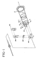
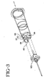
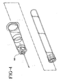
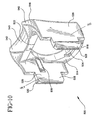
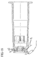
- FIG. 2 illustrates a holder 10 for a blood collection needle comprising a housing 20 and an actuation mechanism 100 .
- housing 20 has a top end 22 , an upper section 24 , and a bottom end 26 .
- a first sidewall 28 extends from top end 22 to a shoulder 23 and a second sidewall 30 extends from shoulder 23 to bottom end 26 .
- First sidewall comprises an inner surface 34 and an outer surface 36 and second sidewall comprises an inner surface 38 and an outer surface 40 .
- the inner diameter 44 of second sidewall 30 is larger than the inner diameter 42 of first sidewall 28 .
- a projection 43 is integrally formed on outer surface 34 of the first sidewall.
- the holder further includes a sleeve 50 removably inserted in the bottom end of the housing.
- Sleeve 50 comprises a body 52 and flange 54 .
- Flange 54 extends outwardly from the rearward end 56 of the sleeve to support the holder on a flat surface and also to provide the user with a means for gripping the holder.
- top surface 60 At top end 22 of the housing there is a top surface 60 .
- top surface 60 At top surface 60 there is an aperture 62 , a pair of side openings 64 , a pair of projecting guide arms 66 that extend upwardly from the top surface and a recessed surface 68 surrounding the aperture.
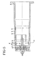
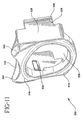
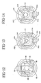
- actuation mechanism 100 includes a retainer 200 , a first slider 300 , a second slider 400 and a frame 500 .
- retainer 200 includes a bottom platform 210 , an upper platform 212 and a half female member 214 extending between the bottom and upper platforms.
- Bottom platform 210 has a larger surface area than upper platform 212 .
- Half female member 214 includes an opening 216 and threads 218 .
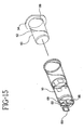
- first slider or engaging trigger 300 includes a body 320 comprising a top surface 322 , a bottom surface 324 , a rearward end 326 and a forward end 328 .
- a pair of arms 340 extend from the forward end of the body. Arms 340 each include a forward end 342 , a rearward end 343 , an inner surface 346 and an outer surface 348 . At the rearward end 342 of each arm is a hook 344 and on the outer surface of each arm is an indentation or groove 350 .
- a half female member 352 extends from the rearward end of the body and includes threads 354 .
- Rearward end 326 includes a finger guide 356 and on bottom surface 324 of the body at rearward end 326 is a downwardly extending flange 360 .
- second slider or disengaging trigger 400 includes a frame 410 that surrounds a cavity 412 .
- Frame 410 includes a forward end 414 , a rearward end 416 , a bottom surface 418 and an upper surface 420 .
- Sidewalls 422 extend between the forward end and the rearward end of the frame. Sidewalls 422 include an outer surface 424 and an inner surface 426 and an indentation or cutout 436 on the outer surface of each sidewall.
- Cavity 412 includes a stopping end 428 at forward end 414 .
- At rearward end 416 on upper surface 420 is a raised ledge 430 .
- Raised ledge 430 includes a rearward end 432 and a forward end 434 .
- finger guide 440 for providing the user with finger identification for locating and using the disengaging trigger.
- Finger guide 440 is distinct from finger guide 356 of the first slider so that the user may easily distinguish the disengaging trigger from the engaging trigger.
- the finger guides may be structurally distinct as well as color coded. For example, the finger guide for the disengaging trigger may be green and the finger guide for the engaging trigger may be blue.
- Sidewalls 422 further include cutouts 436 on the outer surface of each sidewall.
- frame 500 includes a top wall 510 comprising a top surface 512 , a bottom surface 514 , a forward end 516 , a rearward end 518 and a bore 520 surrounded by top surface 512 .
- a recess 522 At bottom surface 514 at forward end 516 is a recess 522 and at rearward end 518 is another recess 524 .
- Extending downwardly from top wall 510 are a pair of guidewalls 526 .
- Extending downwardly from guidewalls 526 are feet 528 with hooks 530 .
- Guidewalls 526 include an inner surface 532 and an outer surface 534 .
- On inner surface 532 are protrusions 536 .
- At forward end 516 is a recess indicator 540 that extends into indicator guides 542 .
- Indicator guides 542 extend radially forward and at an incline upwardly from forward end 516 and recess indicator 540 .
- the four parts of the actuation mechanism 100 , retainer 200 , first slider or engaging trigger 300 , second slider or disengaging trigger 400 and frame 500 , are arranged relative to each other in the manner shown in FIGS. 1, 6, 7, 8 and 9.
- retainer 200 fits with forward end 516 of frame 500 in recess 522 .
- First slider 300 is associated with the rearward end of frame 500 whereby the top surface 322 of the first slider faces bottom surface 514 of the frame and indentations 350 of the first slider engage with protrusions 536 of guidewalls 526 .
- Half female member 352 of the first slider faces half female member 214 of retainer 200 to from a threaded passageway where the hub of a needle assembly is engaged.
- Cavity 412 of second slider 400 surrounds half female members 352 and 214 of the first slider and retainer respectively. Lug 438 fits within opening 216 of half female member 214 of retainer 200 .
- the actuation mechanism is then secured to top surface 60 of holder 10 , whereby hooks 530 of feet 528 of the frame engage with pair openings 64 in the top surface of the holder.
- the projecting guide arms 66 in the top surface of the holder are to assist in guiding the attachment of the actuation mechanism to the holder.
- the actuation mechanism is moved into a closed position when rearward end 326 of the first slider is pushed forward with the user's finger using finger guide 356 as shown in FIG. 16.
- indentations 350 engage with protrusions 536 of guidewalls 526 and female half member 352 moves to meet with female half member 214 of retainer 200 to form a threaded passageway so that the hub of a conventional needle can be secured in the passageway.
- the actuation mechanism is moved into the open position when rearward end 432 of the second slider is pushed forward towards the first slider whereby the user pushes the slider at the finger guide 440 .
- cutout 436 pushes arms 340 of the first slider so that indentations 350 disengage from protrusions 536 of the guidewalls, and the first slider moves backwards but not beyond the point when stopping end 428 of cavity 412 holds half female member 352 of the first slider.
- the recess indicators 542 and indicator guides 542 deter the user from touching the needle and the prevention of premature release of the needle whereby the guides act as a shield between the patient's skin and the disengaging trigger.
- indicator guides 542 rest upon the patient's skin so that the patient's skin does not prematurely trigger disengaging trigger 400 at finger guide 440 .
- recess indicator 540 provides the user with notification that the disengaging trigger is near and therefore prevents the user from prematurely activating the disengaging trigger.
Landscapes
- Health & Medical Sciences (AREA)
- Life Sciences & Earth Sciences (AREA)
- Animal Behavior & Ethology (AREA)
- Hematology (AREA)
- Veterinary Medicine (AREA)
- Public Health (AREA)
- Engineering & Computer Science (AREA)
- Biomedical Technology (AREA)
- Heart & Thoracic Surgery (AREA)
- General Health & Medical Sciences (AREA)
- Pathology (AREA)
- Surgery (AREA)
- Molecular Biology (AREA)
- Medical Informatics (AREA)
- Biophysics (AREA)
- Physics & Mathematics (AREA)
- Vascular Medicine (AREA)
- Anesthesiology (AREA)
- Infusion, Injection, And Reservoir Apparatuses (AREA)
- Measurement Of The Respiration, Hearing Ability, Form, And Blood Characteristics Of Living Organisms (AREA)
Claims (9)
- Ensemble support pour une aiguille de prélèvement de sang comprenant un corps tubulaire (20) présentant une extrémité supérieure (22), et une extrémité inférieure ouverte (26) et une paroi latérale (28, 30) s'étendant entre ladite extrémité supérieure et ladite extrémité inférieure et une ouverture (62) dans ladite extrémité supérieure ;
un mécanisme d'activation d'aiguille (100) situé sur ladite extrémité supérieure dudit corps tubulaire comprenant une voie de passage filetée (214, 352) alignée avec ladite ouverture, un poussoir de séparation (400) et un poussoir de couplage (300) fixés sur ladite voie de passage filetée, dans lequel ledit poussoir de séparation sert à séparer un manchon d'aiguille fileté de ladite voie de passage filetée ; et
un indicateur de prévention de libération d'aiguille sur ledit mécanisme d'activation (100),
caractérisé en ce que l'indicateur de prévention de libération d'aiguille comprend une cavité de doigt (540) et au moins un guide d'indicateur (542), de telle sorte que ledit indicateur empêche le déplacement prématuré dudit poussoir de séparation (400). - Support d'aiguille selon la revendication 1, dans lequel ladite voie de passage filetée (214, 352) présente une position ouverte avec une surface de section transversale ouverte de telle sorte que la surface de section transversale ouverte de la voie de passage filetée est supérieure à la surface de section transversale du manchon d'une aiguille, et une position fermée avec une surface de section transversale fermée de telle sorte que la surface de section transversale fermée de la voie de passage filetée est inférieure à la surface de section transversale du manchon d'une aiguille.
- Support d'aiguille selon la revendication 2, dans lequel ledit poussoir de couplage (300) forme un moyen destiné à placer ladite voie de passage filetée dans ladite position fermée.
- Support d'aiguille selon la revendication 3, dans lequel le ledit poussoir de séparation (400) forme un moyen destiné à placer ladite voie de passage filetée dans ladite position ouverte.
- Support d'aiguille selon la revendication 1, dans lequel ladite cavité de doigt (540) est agencée entre lesdits guides d'indicateur (542).
- Support d'aiguille selon la revendication 1, dans lequel ledit indicateur de prévention de libération d'aiguille est située au-dessus dudit poussoir de séparation 400.
- Support d'aiguille selon la revendication 1, dans lequel ledit poussoir de séparation et ledit poussoir de couplage sont situés à l'opposé l'un de l'autre.
- Support d'aiguille selon la revendication 1, dans lequel ledit poussoir de séparation comprend un premier indicateur de doigt et le poussoir de couplage comprend un second indicateur de doigt distinct du premier indicateur de doigt.
- Support d'aiguille selon la revendication 8, dans lequel les premier et second indicateurs de doigt sont différenciés par une couleur, par une texture, ou à la fois par une couleur et une texture.
Applications Claiming Priority (2)
| Application Number | Priority Date | Filing Date | Title |
|---|---|---|---|
| US7799698P | 1998-03-13 | 1998-03-13 | |
| US77996P | 1998-03-13 |
Publications (3)
| Publication Number | Publication Date |
|---|---|
| EP0943352A2 EP0943352A2 (fr) | 1999-09-22 |
| EP0943352A3 EP0943352A3 (fr) | 2000-04-12 |
| EP0943352B1 true EP0943352B1 (fr) | 2004-07-28 |
Family
ID=22141238
Family Applications (1)
| Application Number | Title | Priority Date | Filing Date |
|---|---|---|---|
| EP99104951A Expired - Lifetime EP0943352B1 (fr) | 1998-03-13 | 1999-03-12 | Assemblage de porte-aiguille |
Country Status (6)
| Country | Link |
|---|---|
| US (1) | US6306118B1 (fr) |
| EP (1) | EP0943352B1 (fr) |
| JP (1) | JP4410870B2 (fr) |
| AU (1) | AU750015B2 (fr) |
| DE (1) | DE69918882T2 (fr) |
| ES (1) | ES2221252T3 (fr) |
Families Citing this family (10)
| Publication number | Priority date | Publication date | Assignee | Title |
|---|---|---|---|---|
| US7435231B2 (en) | 1999-07-29 | 2008-10-14 | Fenwal, Inc. | Biological sample device receiver |
| US20030183546A1 (en) * | 2002-03-28 | 2003-10-02 | Becton, Dickinson And Company | Needle-disposable insert for sharps disposal |
| US20040176705A1 (en) * | 2003-03-04 | 2004-09-09 | Stevens Timothy A. | Cartridge having an integrated collection element for point of care system |
| US20040176704A1 (en) * | 2003-03-04 | 2004-09-09 | Stevens Timothy A | Collection device adapted to accept cartridge for point of care system |
| DE10348603A1 (de) * | 2003-10-20 | 2005-05-19 | Klinika Medical Gmbh | Kanülenhalter mit Kanülenentsorgung |
| CN101711903A (zh) * | 2004-04-07 | 2010-05-26 | 株式会社Jms | 带接合器的注射器和注射器用接合器以及注射器 |
| US7842008B2 (en) | 2005-11-21 | 2010-11-30 | Becton, Dickinson And Company | Intradermal delivery device |
| US9320459B2 (en) | 2006-05-08 | 2016-04-26 | Becton, Dickinson And Company | Gravity-drop safety holder |
| RU186390U1 (ru) * | 2017-10-05 | 2019-01-17 | Владимир Павлович Акимов | Держатель иглы системы вакуумного забора крови |
| CN114869423B (zh) * | 2022-05-12 | 2023-03-24 | 连云港市妇幼保健院(连云港市第三人民医院) | 一种具有拆装和锁定功能的疼痛科穿刺注射针管架 |
Family Cites Families (6)
| Publication number | Priority date | Publication date | Assignee | Title |
|---|---|---|---|---|
| DE69023124T2 (de) * | 1989-02-01 | 1996-11-14 | Sero Guard Corp | Selbsttätiger nadelschutz für eine wegwerfbare, hypodermische spritze. |
| US5443287B1 (en) * | 1993-11-18 | 2000-12-05 | Galen Wells | Quick release ski pole and strap system |
| US5616136A (en) | 1995-01-09 | 1997-04-01 | Med-Safe Systems, Inc. | Quick release needle removal apparatus |
| JP2723105B2 (ja) * | 1995-11-22 | 1998-03-09 | 株式会社ニッショー | 採血針ホルダー |
| CA2241631C (fr) * | 1995-12-28 | 2002-10-15 | Bio-Plexus, Inc. | Porte-aiguille pour dispositif d'injection et/ou de prelevement de fluide |
| JP3531149B2 (ja) | 1996-07-31 | 2004-05-24 | ニプロ株式会社 | 採血針廃棄容器 |
-
1999
- 1999-03-10 US US09/266,163 patent/US6306118B1/en not_active Expired - Lifetime
- 1999-03-12 DE DE69918882T patent/DE69918882T2/de not_active Expired - Lifetime
- 1999-03-12 ES ES99104951T patent/ES2221252T3/es not_active Expired - Lifetime
- 1999-03-12 EP EP99104951A patent/EP0943352B1/fr not_active Expired - Lifetime
- 1999-03-15 AU AU21201/99A patent/AU750015B2/en not_active Expired
- 1999-03-15 JP JP06908499A patent/JP4410870B2/ja not_active Expired - Lifetime
Also Published As
| Publication number | Publication date |
|---|---|
| AU750015B2 (en) | 2002-07-11 |
| US6306118B1 (en) | 2001-10-23 |
| JPH11318869A (ja) | 1999-11-24 |
| EP0943352A3 (fr) | 2000-04-12 |
| ES2221252T3 (es) | 2004-12-16 |
| AU2120199A (en) | 1999-09-23 |
| DE69918882D1 (de) | 2004-09-02 |
| DE69918882T2 (de) | 2005-08-11 |
| EP0943352A2 (fr) | 1999-09-22 |
| JP4410870B2 (ja) | 2010-02-03 |
Similar Documents
| Publication | Publication Date | Title |
|---|---|---|
| EP0719564B1 (fr) | Dispositif de sécurité pour l'insertion d'une canule | |
| US6059756A (en) | Safety injection device | |
| US4904242A (en) | Phlebotomy set with safety retracting needle | |
| US4927414A (en) | Syringe with safety retracting needle | |
| EP0568525B1 (fr) | Seringue hypodermique | |
| US6582402B1 (en) | Catheter-advancement actuated needle retraction system | |
| US7699813B2 (en) | Medical needle assemblies | |
| US5795339A (en) | Catheter-advancement actuated needle retraction system | |
| US4846811A (en) | Sliding sheath for medical needles | |
| EP0995455B1 (fr) | Assemblage de recouvrement protecteur | |
| CA1337167C (fr) | Gaine avec aiguille retractable | |
| JP3610304B2 (ja) | 翼付きi.v.装置 | |
| US6969376B2 (en) | Safety indwelling needle | |
| US5135510A (en) | Hypodermic syringe | |
| WO1993000942A1 (fr) | Ensemble capuchon | |
| JPH10127767A (ja) | 片手操作可能な針バリアーを備えた針アセンブリ | |
| JP2003325482A (ja) | 安全装置付き血液採取用針アセンブリ | |
| EP0943352B1 (fr) | Assemblage de porte-aiguille | |
| JP4611627B2 (ja) | 針組み立て品 | |
| US5709667A (en) | Hypodermic needle protection system | |
| JP2647132B2 (ja) | 安全後退用針を備えたカニューレ挿入装置 | |
| EP0962230B1 (fr) | Dispositif d'aiguille, en particulier aiguille hypodermique | |
| WO2007121505A1 (fr) | Ensemble aiguille |
Legal Events
| Date | Code | Title | Description |
|---|---|---|---|
| PUAI | Public reference made under article 153(3) epc to a published international application that has entered the european phase |
Free format text: ORIGINAL CODE: 0009012 |
|
| AK | Designated contracting states |
Kind code of ref document: A2 Designated state(s): DE ES FR GB IT |
|
| AX | Request for extension of the european patent |
Free format text: AL;LT;LV;MK;RO;SI |
|
| PUAL | Search report despatched |
Free format text: ORIGINAL CODE: 0009013 |
|
| AK | Designated contracting states |
Kind code of ref document: A3 Designated state(s): AT BE CH CY DE DK ES FI FR GB GR IE IT LI LU MC NL PT SE |
|
| AX | Request for extension of the european patent |
Free format text: AL;LT;LV;MK;RO;SI |
|
| RIC1 | Information provided on ipc code assigned before grant |
Free format text: 7A 61M 5/32 A, 7A 61M 5/34 B |
|
| 17P | Request for examination filed |
Effective date: 20000526 |
|
| AKX | Designation fees paid |
Free format text: DE ES FR GB IT |
|
| 17Q | First examination report despatched |
Effective date: 20030129 |
|
| GRAP | Despatch of communication of intention to grant a patent |
Free format text: ORIGINAL CODE: EPIDOSNIGR1 |
|
| GRAP | Despatch of communication of intention to grant a patent |
Free format text: ORIGINAL CODE: EPIDOSNIGR1 |
|
| GRAS | Grant fee paid |
Free format text: ORIGINAL CODE: EPIDOSNIGR3 |
|
| GRAA | (expected) grant |
Free format text: ORIGINAL CODE: 0009210 |
|
| AK | Designated contracting states |
Kind code of ref document: B1 Designated state(s): DE ES FR GB IT |
|
| REG | Reference to a national code |
Ref country code: GB Ref legal event code: FG4D |
|
| REF | Corresponds to: |
Ref document number: 69918882 Country of ref document: DE Date of ref document: 20040902 Kind code of ref document: P |
|
| REG | Reference to a national code |
Ref country code: ES Ref legal event code: FG2A Ref document number: 2221252 Country of ref document: ES Kind code of ref document: T3 |
|
| ET | Fr: translation filed | ||
| PGFP | Annual fee paid to national office [announced via postgrant information from national office to epo] |
Ref country code: ES Payment date: 20050407 Year of fee payment: 7 |
|
| PLBE | No opposition filed within time limit |
Free format text: ORIGINAL CODE: 0009261 |
|
| STAA | Information on the status of an ep patent application or granted ep patent |
Free format text: STATUS: NO OPPOSITION FILED WITHIN TIME LIMIT |
|
| 26N | No opposition filed |
Effective date: 20050429 |
|
| PGFP | Annual fee paid to national office [announced via postgrant information from national office to epo] |
Ref country code: FR Payment date: 20060317 Year of fee payment: 8 |
|
| REG | Reference to a national code |
Ref country code: FR Ref legal event code: ST Effective date: 20071130 |
|
| REG | Reference to a national code |
Ref country code: ES Ref legal event code: FD2A Effective date: 20070313 |
|
| PG25 | Lapsed in a contracting state [announced via postgrant information from national office to epo] |
Ref country code: FR Free format text: LAPSE BECAUSE OF NON-PAYMENT OF DUE FEES Effective date: 20070402 Ref country code: ES Free format text: LAPSE BECAUSE OF NON-PAYMENT OF DUE FEES Effective date: 20070313 |
|
| PGFP | Annual fee paid to national office [announced via postgrant information from national office to epo] |
Ref country code: GB Payment date: 20180226 Year of fee payment: 20 Ref country code: DE Payment date: 20180219 Year of fee payment: 20 |
|
| PGFP | Annual fee paid to national office [announced via postgrant information from national office to epo] |
Ref country code: IT Payment date: 20180219 Year of fee payment: 20 |
|
| REG | Reference to a national code |
Ref country code: DE Ref legal event code: R071 Ref document number: 69918882 Country of ref document: DE |
|
| REG | Reference to a national code |
Ref country code: GB Ref legal event code: PE20 Expiry date: 20190311 |
|
| PG25 | Lapsed in a contracting state [announced via postgrant information from national office to epo] |
Ref country code: GB Free format text: LAPSE BECAUSE OF EXPIRATION OF PROTECTION Effective date: 20190311 |