EP0943304B1 - Schraubpfanne für eine Hüftgelenksprothese - Google Patents
Schraubpfanne für eine Hüftgelenksprothese Download PDFInfo
- Publication number
- EP0943304B1 EP0943304B1 EP98250441A EP98250441A EP0943304B1 EP 0943304 B1 EP0943304 B1 EP 0943304B1 EP 98250441 A EP98250441 A EP 98250441A EP 98250441 A EP98250441 A EP 98250441A EP 0943304 B1 EP0943304 B1 EP 0943304B1
- Authority
- EP
- European Patent Office
- Prior art keywords
- thread
- flanks
- acetabular cup
- essentially
- tool
- Prior art date
- Legal status (The legal status is an assumption and is not a legal conclusion. Google has not performed a legal analysis and makes no representation as to the accuracy of the status listed.)
- Expired - Lifetime
Links
- 210000004394 hip joint Anatomy 0.000 title claims description 7
- 210000001981 hip bone Anatomy 0.000 claims description 66
- 238000004519 manufacturing process Methods 0.000 claims description 35
- 238000000034 method Methods 0.000 claims description 23
- 238000003801 milling Methods 0.000 claims description 14
- 238000010079 rubber tapping Methods 0.000 claims description 10
- 238000012545 processing Methods 0.000 claims description 6
- 238000006073 displacement reaction Methods 0.000 claims description 4
- 238000004873 anchoring Methods 0.000 claims description 2
- 230000001052 transient effect Effects 0.000 claims 4
- 238000005520 cutting process Methods 0.000 description 17
- 210000000988 bone and bone Anatomy 0.000 description 12
- 230000007704 transition Effects 0.000 description 10
- 230000002349 favourable effect Effects 0.000 description 6
- 238000013461 design Methods 0.000 description 5
- 230000000694 effects Effects 0.000 description 5
- 238000011161 development Methods 0.000 description 4
- 230000018109 developmental process Effects 0.000 description 4
- 230000003313 weakening effect Effects 0.000 description 4
- 230000006978 adaptation Effects 0.000 description 3
- 238000000227 grinding Methods 0.000 description 3
- 238000007514 turning Methods 0.000 description 3
- 238000005516 engineering process Methods 0.000 description 2
- 230000012010 growth Effects 0.000 description 2
- 230000000977 initiatory effect Effects 0.000 description 2
- 238000003754 machining Methods 0.000 description 2
- 230000013011 mating Effects 0.000 description 2
- 238000002360 preparation method Methods 0.000 description 2
- 210000000689 upper leg Anatomy 0.000 description 2
- 241000309551 Arthraxon hispidus Species 0.000 description 1
- 238000013459 approach Methods 0.000 description 1
- 239000000560 biocompatible material Substances 0.000 description 1
- 230000008468 bone growth Effects 0.000 description 1
- 238000010276 construction Methods 0.000 description 1
- 230000001419 dependent effect Effects 0.000 description 1
- 230000037231 joint health Effects 0.000 description 1
- 239000000463 material Substances 0.000 description 1
- 239000002184 metal Substances 0.000 description 1
- 229910001092 metal group alloy Inorganic materials 0.000 description 1
- 238000012805 post-processing Methods 0.000 description 1
- 238000007781 pre-processing Methods 0.000 description 1
- 238000002271 resection Methods 0.000 description 1
- 239000000126 substance Substances 0.000 description 1
- 238000001356 surgical procedure Methods 0.000 description 1
- 230000008961 swelling Effects 0.000 description 1
- 238000012546 transfer Methods 0.000 description 1
Images


Classifications
-
- A—HUMAN NECESSITIES
- A61—MEDICAL OR VETERINARY SCIENCE; HYGIENE
- A61F—FILTERS IMPLANTABLE INTO BLOOD VESSELS; PROSTHESES; DEVICES PROVIDING PATENCY TO, OR PREVENTING COLLAPSING OF, TUBULAR STRUCTURES OF THE BODY, e.g. STENTS; ORTHOPAEDIC, NURSING OR CONTRACEPTIVE DEVICES; FOMENTATION; TREATMENT OR PROTECTION OF EYES OR EARS; BANDAGES, DRESSINGS OR ABSORBENT PADS; FIRST-AID KITS
- A61F2/00—Filters implantable into blood vessels; Prostheses, i.e. artificial substitutes or replacements for parts of the body; Appliances for connecting them with the body; Devices providing patency to, or preventing collapsing of, tubular structures of the body, e.g. stents
- A61F2/02—Prostheses implantable into the body
- A61F2/30—Joints
- A61F2/32—Joints for the hip
- A61F2/34—Acetabular cups
-
- B—PERFORMING OPERATIONS; TRANSPORTING
- B23—MACHINE TOOLS; METAL-WORKING NOT OTHERWISE PROVIDED FOR
- B23G—THREAD CUTTING; WORKING OF SCREWS, BOLT HEADS, OR NUTS, IN CONJUNCTION THEREWITH
- B23G5/00—Thread-cutting tools; Die-heads
- B23G5/02—Thread-cutting tools; Die-heads without means for adjustment
- B23G5/06—Taps
-
- A—HUMAN NECESSITIES
- A61—MEDICAL OR VETERINARY SCIENCE; HYGIENE
- A61F—FILTERS IMPLANTABLE INTO BLOOD VESSELS; PROSTHESES; DEVICES PROVIDING PATENCY TO, OR PREVENTING COLLAPSING OF, TUBULAR STRUCTURES OF THE BODY, e.g. STENTS; ORTHOPAEDIC, NURSING OR CONTRACEPTIVE DEVICES; FOMENTATION; TREATMENT OR PROTECTION OF EYES OR EARS; BANDAGES, DRESSINGS OR ABSORBENT PADS; FIRST-AID KITS
- A61F2/00—Filters implantable into blood vessels; Prostheses, i.e. artificial substitutes or replacements for parts of the body; Appliances for connecting them with the body; Devices providing patency to, or preventing collapsing of, tubular structures of the body, e.g. stents
- A61F2/02—Prostheses implantable into the body
- A61F2/30—Joints
- A61F2/3094—Designing or manufacturing processes
-
- A—HUMAN NECESSITIES
- A61—MEDICAL OR VETERINARY SCIENCE; HYGIENE
- A61F—FILTERS IMPLANTABLE INTO BLOOD VESSELS; PROSTHESES; DEVICES PROVIDING PATENCY TO, OR PREVENTING COLLAPSING OF, TUBULAR STRUCTURES OF THE BODY, e.g. STENTS; ORTHOPAEDIC, NURSING OR CONTRACEPTIVE DEVICES; FOMENTATION; TREATMENT OR PROTECTION OF EYES OR EARS; BANDAGES, DRESSINGS OR ABSORBENT PADS; FIRST-AID KITS
- A61F2/00—Filters implantable into blood vessels; Prostheses, i.e. artificial substitutes or replacements for parts of the body; Appliances for connecting them with the body; Devices providing patency to, or preventing collapsing of, tubular structures of the body, e.g. stents
- A61F2/02—Prostheses implantable into the body
- A61F2/30—Joints
- A61F2002/30001—Additional features of subject-matter classified in A61F2/28, A61F2/30 and subgroups thereof
- A61F2002/30316—The prosthesis having different structural features at different locations within the same prosthesis; Connections between prosthetic parts; Special structural features of bone or joint prostheses not otherwise provided for
- A61F2002/30317—The prosthesis having different structural features at different locations within the same prosthesis
- A61F2002/30326—The prosthesis having different structural features at different locations within the same prosthesis differing in height or in length
-
- A—HUMAN NECESSITIES
- A61—MEDICAL OR VETERINARY SCIENCE; HYGIENE
- A61F—FILTERS IMPLANTABLE INTO BLOOD VESSELS; PROSTHESES; DEVICES PROVIDING PATENCY TO, OR PREVENTING COLLAPSING OF, TUBULAR STRUCTURES OF THE BODY, e.g. STENTS; ORTHOPAEDIC, NURSING OR CONTRACEPTIVE DEVICES; FOMENTATION; TREATMENT OR PROTECTION OF EYES OR EARS; BANDAGES, DRESSINGS OR ABSORBENT PADS; FIRST-AID KITS
- A61F2/00—Filters implantable into blood vessels; Prostheses, i.e. artificial substitutes or replacements for parts of the body; Appliances for connecting them with the body; Devices providing patency to, or preventing collapsing of, tubular structures of the body, e.g. stents
- A61F2/02—Prostheses implantable into the body
- A61F2/30—Joints
- A61F2002/30001—Additional features of subject-matter classified in A61F2/28, A61F2/30 and subgroups thereof
- A61F2002/30316—The prosthesis having different structural features at different locations within the same prosthesis; Connections between prosthetic parts; Special structural features of bone or joint prostheses not otherwise provided for
- A61F2002/30329—Connections or couplings between prosthetic parts, e.g. between modular parts; Connecting elements
- A61F2002/30331—Connections or couplings between prosthetic parts, e.g. between modular parts; Connecting elements made by longitudinally pushing a protrusion into a complementarily-shaped recess, e.g. held by friction fit
- A61F2002/30332—Conically- or frustoconically-shaped protrusion and recess
- A61F2002/30345—Multiple conical connection, i.e. the protrusion and recess having several tapered sections of different complementary conicities
-
- A—HUMAN NECESSITIES
- A61—MEDICAL OR VETERINARY SCIENCE; HYGIENE
- A61F—FILTERS IMPLANTABLE INTO BLOOD VESSELS; PROSTHESES; DEVICES PROVIDING PATENCY TO, OR PREVENTING COLLAPSING OF, TUBULAR STRUCTURES OF THE BODY, e.g. STENTS; ORTHOPAEDIC, NURSING OR CONTRACEPTIVE DEVICES; FOMENTATION; TREATMENT OR PROTECTION OF EYES OR EARS; BANDAGES, DRESSINGS OR ABSORBENT PADS; FIRST-AID KITS
- A61F2/00—Filters implantable into blood vessels; Prostheses, i.e. artificial substitutes or replacements for parts of the body; Appliances for connecting them with the body; Devices providing patency to, or preventing collapsing of, tubular structures of the body, e.g. stents
- A61F2/02—Prostheses implantable into the body
- A61F2/30—Joints
- A61F2/30767—Special external or bone-contacting surface, e.g. coating for improving bone ingrowth
- A61F2/30771—Special external or bone-contacting surface, e.g. coating for improving bone ingrowth applied in original prostheses, e.g. holes or grooves
- A61F2002/3085—Special external or bone-contacting surface, e.g. coating for improving bone ingrowth applied in original prostheses, e.g. holes or grooves with a threaded, e.g. self-tapping, bone-engaging surface, e.g. external surface
- A61F2002/30851—Multiple threadings
-
- A—HUMAN NECESSITIES
- A61—MEDICAL OR VETERINARY SCIENCE; HYGIENE
- A61F—FILTERS IMPLANTABLE INTO BLOOD VESSELS; PROSTHESES; DEVICES PROVIDING PATENCY TO, OR PREVENTING COLLAPSING OF, TUBULAR STRUCTURES OF THE BODY, e.g. STENTS; ORTHOPAEDIC, NURSING OR CONTRACEPTIVE DEVICES; FOMENTATION; TREATMENT OR PROTECTION OF EYES OR EARS; BANDAGES, DRESSINGS OR ABSORBENT PADS; FIRST-AID KITS
- A61F2/00—Filters implantable into blood vessels; Prostheses, i.e. artificial substitutes or replacements for parts of the body; Appliances for connecting them with the body; Devices providing patency to, or preventing collapsing of, tubular structures of the body, e.g. stents
- A61F2/02—Prostheses implantable into the body
- A61F2/30—Joints
- A61F2/30767—Special external or bone-contacting surface, e.g. coating for improving bone ingrowth
- A61F2/30771—Special external or bone-contacting surface, e.g. coating for improving bone ingrowth applied in original prostheses, e.g. holes or grooves
- A61F2002/3085—Special external or bone-contacting surface, e.g. coating for improving bone ingrowth applied in original prostheses, e.g. holes or grooves with a threaded, e.g. self-tapping, bone-engaging surface, e.g. external surface
- A61F2002/30864—Microthreads
-
- A—HUMAN NECESSITIES
- A61—MEDICAL OR VETERINARY SCIENCE; HYGIENE
- A61F—FILTERS IMPLANTABLE INTO BLOOD VESSELS; PROSTHESES; DEVICES PROVIDING PATENCY TO, OR PREVENTING COLLAPSING OF, TUBULAR STRUCTURES OF THE BODY, e.g. STENTS; ORTHOPAEDIC, NURSING OR CONTRACEPTIVE DEVICES; FOMENTATION; TREATMENT OR PROTECTION OF EYES OR EARS; BANDAGES, DRESSINGS OR ABSORBENT PADS; FIRST-AID KITS
- A61F2/00—Filters implantable into blood vessels; Prostheses, i.e. artificial substitutes or replacements for parts of the body; Appliances for connecting them with the body; Devices providing patency to, or preventing collapsing of, tubular structures of the body, e.g. stents
- A61F2/02—Prostheses implantable into the body
- A61F2/30—Joints
- A61F2/32—Joints for the hip
- A61F2/34—Acetabular cups
- A61F2002/3401—Acetabular cups with radial apertures, e.g. radial bores for receiving fixation screws
- A61F2002/3403—Polar aperture
-
- A—HUMAN NECESSITIES
- A61—MEDICAL OR VETERINARY SCIENCE; HYGIENE
- A61F—FILTERS IMPLANTABLE INTO BLOOD VESSELS; PROSTHESES; DEVICES PROVIDING PATENCY TO, OR PREVENTING COLLAPSING OF, TUBULAR STRUCTURES OF THE BODY, e.g. STENTS; ORTHOPAEDIC, NURSING OR CONTRACEPTIVE DEVICES; FOMENTATION; TREATMENT OR PROTECTION OF EYES OR EARS; BANDAGES, DRESSINGS OR ABSORBENT PADS; FIRST-AID KITS
- A61F2/00—Filters implantable into blood vessels; Prostheses, i.e. artificial substitutes or replacements for parts of the body; Appliances for connecting them with the body; Devices providing patency to, or preventing collapsing of, tubular structures of the body, e.g. stents
- A61F2/02—Prostheses implantable into the body
- A61F2/30—Joints
- A61F2/32—Joints for the hip
- A61F2/34—Acetabular cups
- A61F2002/3453—Acetabular cups having a non-hemispherical convex outer surface, e.g. quadric-shaped
- A61F2002/3456—Acetabular cups having a non-hemispherical convex outer surface, e.g. quadric-shaped ellipsoidal or having a flattened polar region
-
- A—HUMAN NECESSITIES
- A61—MEDICAL OR VETERINARY SCIENCE; HYGIENE
- A61F—FILTERS IMPLANTABLE INTO BLOOD VESSELS; PROSTHESES; DEVICES PROVIDING PATENCY TO, OR PREVENTING COLLAPSING OF, TUBULAR STRUCTURES OF THE BODY, e.g. STENTS; ORTHOPAEDIC, NURSING OR CONTRACEPTIVE DEVICES; FOMENTATION; TREATMENT OR PROTECTION OF EYES OR EARS; BANDAGES, DRESSINGS OR ABSORBENT PADS; FIRST-AID KITS
- A61F2/00—Filters implantable into blood vessels; Prostheses, i.e. artificial substitutes or replacements for parts of the body; Appliances for connecting them with the body; Devices providing patency to, or preventing collapsing of, tubular structures of the body, e.g. stents
- A61F2/02—Prostheses implantable into the body
- A61F2/30—Joints
- A61F2/32—Joints for the hip
- A61F2/34—Acetabular cups
- A61F2002/3453—Acetabular cups having a non-hemispherical convex outer surface, e.g. quadric-shaped
- A61F2002/3462—Acetabular cups having a non-hemispherical convex outer surface, e.g. quadric-shaped having a frustoconical external shape, e.g. entirely frustoconical
-
- A—HUMAN NECESSITIES
- A61—MEDICAL OR VETERINARY SCIENCE; HYGIENE
- A61F—FILTERS IMPLANTABLE INTO BLOOD VESSELS; PROSTHESES; DEVICES PROVIDING PATENCY TO, OR PREVENTING COLLAPSING OF, TUBULAR STRUCTURES OF THE BODY, e.g. STENTS; ORTHOPAEDIC, NURSING OR CONTRACEPTIVE DEVICES; FOMENTATION; TREATMENT OR PROTECTION OF EYES OR EARS; BANDAGES, DRESSINGS OR ABSORBENT PADS; FIRST-AID KITS
- A61F2220/00—Fixations or connections for prostheses classified in groups A61F2/00 - A61F2/26 or A61F2/82 or A61F9/00 or A61F11/00 or subgroups thereof
- A61F2220/0025—Connections or couplings between prosthetic parts, e.g. between modular parts; Connecting elements
- A61F2220/0033—Connections or couplings between prosthetic parts, e.g. between modular parts; Connecting elements made by longitudinally pushing a protrusion into a complementary-shaped recess, e.g. held by friction fit
-
- A—HUMAN NECESSITIES
- A61—MEDICAL OR VETERINARY SCIENCE; HYGIENE
- A61F—FILTERS IMPLANTABLE INTO BLOOD VESSELS; PROSTHESES; DEVICES PROVIDING PATENCY TO, OR PREVENTING COLLAPSING OF, TUBULAR STRUCTURES OF THE BODY, e.g. STENTS; ORTHOPAEDIC, NURSING OR CONTRACEPTIVE DEVICES; FOMENTATION; TREATMENT OR PROTECTION OF EYES OR EARS; BANDAGES, DRESSINGS OR ABSORBENT PADS; FIRST-AID KITS
- A61F2250/00—Special features of prostheses classified in groups A61F2/00 - A61F2/26 or A61F2/82 or A61F9/00 or A61F11/00 or subgroups thereof
- A61F2250/0014—Special features of prostheses classified in groups A61F2/00 - A61F2/26 or A61F2/82 or A61F9/00 or A61F11/00 or subgroups thereof having different values of a given property or geometrical feature, e.g. mechanical property or material property, at different locations within the same prosthesis
- A61F2250/0037—Special features of prostheses classified in groups A61F2/00 - A61F2/26 or A61F2/82 or A61F9/00 or A61F11/00 or subgroups thereof having different values of a given property or geometrical feature, e.g. mechanical property or material property, at different locations within the same prosthesis differing in height or in length
Definitions
- the invention relates to a screw socket for a hip joint prosthesis according to the preamble of claim 1 as well a process for their preparation.
- the European patent application discloses 0 480 551 A1 a generic spherical screw pan, in which the spherical contour of the main body in Thread base by a number in axial section to each other inclined extending partial surfaces approximated polygonzugartig is.
- the faces form at their respective impact an obtuse-angled roof edge.
- This screw thus also not full surface but only in the area of the roof edges on the hip bone.
- the spherical Contour of the main body by many inclined to each other To approximate partial areas as closely as possible, which however a significantly increased production cost is required.
- Document FR-A-2 610 512 discloses a threaded cup according to the preamble of claim 1.
- the invention is therefore based on the object, a To provide generic screw available, the the disadvantages mentioned or not at least in less Has dimensions, in particular with ease of manufacture the screw pan a uniform introduction the joint loads in the hip bone and a reliable Fixation ensures. Furthermore, the invention is the task is based on a manufacturing process for to specify such a screw.
- the task is, starting from a screw according to the preamble of claim 1, by the in the characterizing Part of claim 1 specified features solved.
- the invention includes the technical teaching that one a quick and easy to manufacture screw with good force introduction in the hip bone gets when on the outside of the main body of the screw between two adjacent flanks of the first thread at least a filling the thread root of the first thread second thread is provided, the local flank height perpendicular to the lateral surface of the body about substantially the entire length of the second thread essential is less than the local flank height of the two adjacent flanks of the first thread. Under local Flanken altar should here in the respective point of Thread measured perpendicular to the lateral surface of the body Distance of the thread crest to the lateral surface of the Basic body be understood.
- the local flank height of the second thread less than the local flank height of the shorter ones the two adjacent flanks.
- the slope of the second thread corresponds to reasons of easier production preferably the pitch of the first thread.
- the second thread arranged in the thread root of the first thread Thread is compared to the known threaded cups one increased contact area and better contact between the screw and the hip bone safely.
- Flank height of the second thread results in the improved Contact between screw cup and hip bone two possibly overlapping effects of the second Thread.
- the flank height of the second thread is so low chosen that ensures that the hip bone is not is significantly weakened by the second thread, like this would be the case, for example, if the flank height of the second thread approximately in the region of the flank height of first thread would be.
- a large amount of living hip bone tissue removed on the other hand would be the strength of the Hip bone due to the relatively short distance reduced between adjacent thread crests Stress cross section and the increased notch effect in the ground of the cut in the hip bone counter thread considerably reduced.
- the invention sufficiently low Flank height of the second thread causes as possible much living bone tissue is preserved and thus the mechanical properties of the bone in Einschraub Scheme to be preserved as much as possible.
- the local flank height of the second thread preferably chosen to be at least one third preferably at least half, is less than the local flank height of possibly shorter of two adjacent flanks of the first thread.
- the local edge height of the second thread preferably essentially less than 95% lower than the local flank height of possibly shorter of the two adjacent flanks of the first thread. It understands It is that the second thread on the one hand over his Length may have a varying edge height. On the other hand can also have adjacent passages of the second thread have different flank height, in particular can separated by the flanks of the first thread Gears of the second thread different flank height exhibit.
- the screw according to the invention may be in principle constructed in conventional manner threaded cups from a biocompatible material, in particular biocompatible Metal or a corresponding metal alloy, acting in the pan interior a recess for Receiving an inlay, for example made of plastic, etc., which then the sliding surface for the anchored in the femur Ball head of the artificial hip joint forms.
- a biocompatible material in particular biocompatible Metal or a corresponding metal alloy
- Screw is the first, alternatively or preferably in addition, the second thread formed self-tapping.
- the screw according to the invention is the first thread, alternatively or additionally the second thread formed more continuous, preferably the number of threads of the second thread an integer Multiples the number of turns of the first thread corresponds.
- the specified number of threads of the second thread as understood relative to a single second thread which is located at the bottom of the first thread and its gears to the individual passages of the first thread are arranged distributed. More preferably, that is first thread in a known manner slaughterhim and the second Thread is formed at least four.
- the terminology above is between two Flanks of the first thread in each case at least two flanks arranged the second thread. This will be a good and uniform filling of the thread of the first thread with a second thread sufficiently lower Flank height achieved.
- the transition region between two flanks in the thread root in the axial section of ringpfanne formed substantially arcuate, for example, elliptical or circular arc, whereby reduces the notch effect in the foot area of the thread teeth is.
- the transition region is essentially circular arc-shaped each being substantially tangential opens into one of the two flanks and a radius of curvature having at most substantially the half flank height of the second thread corresponds. Thanks designed this simple circular arc transition area on the one hand also this area of the first or second thread-generating portion of or Machining tools also very easy. So For example, if this area of the first or second thread-generating tool section at a Turning tool a simple also arcuate Cutting edge on.
- fferpfanne run the distal flanks of the first Thread and the distal flanks of the second thread in the Axial section of the screw socket to the axis of the screw socket at an angle of substantially 70 ° to 90 °, preferably 75 ° to 85 °, inclined.
- the proximal flanks of the first Thread and the proximal flanks of the second thread extend in axial section of the screw also at an angle of substantially 70 ° to 90 °, preferably 75 ° to 85 °, inclined to the axis of the screw. This results both in terms of strength the thread as well as the material pairing made of screw and bone a particularly favorable Slenderness of thread flanks.
- the distal and proximal extend Flanks of the first thread as well as the distal and proximal ones Flanks of the second thread in the axial section of the Screw socket to the axis of the screw to amount tilted at substantially the same angle.
- This advantage in terms of design and guide the thread-generating or the Tools increases even further, if preferably the distal flanks of the first thread and the distal ones Flanks of the second thread and the proximal flanks of the first thread and the proximal flanks of the second Thread to each other substantially parallel. It is for making the first and second threads then possible, one and the same tool geometry, in particular to use the same or the same tools.
- the rotationally symmetrical to the pan axis substantially Mantle surface of the body can essentially the Shape of a truncated cone, an ellipsoidal part or a Paraboloidmaschines have.
- the screw are characterized by a substantially hemispherical shell surface of the main body.
- These spherical cups approach the geometry of the joint of the healthy hip joint better than conical variants. They therefore advantageously require resection on the one hand a lesser amount of living bone tissue and have a similar to the healthy joint load application in the hip bones.
- the invention further relates to a method for machining Production of a screw according to the invention, in the screw in a first sub-step for generating of the first thread with at least a first one Tool and a second tool is edited.
- the remaining flanks of the second thread can in the substantially simultaneously during the first substep getting produced.
- their manufacture can also take place in a second sub-step.
- the first tool is preferably designed such that it simultaneously the distal flank of the first thread and the proximal edge of the distally adjacent portion of the second thread while the second tool so is formed so that it is at the same time the proximal Flank of the first thread and the distal flank of the generated proximal adjacent portion of the second thread.
- the production of the screw is designed doing so very fast and therefore cost, because the flanks of the first thread adjacent and facing Flanks of the second thread after production of the first Thread need not be further processed and In particular, no additional tool required for this is.
- the first thread has more than one turn, so it is done by appropriately sequential editing the pan body with the first and second tools or by simultaneously working with one of the number of gears corresponding number distributed over the pan circumference first and second tools made. Is this second thread thereby formed catchy, so omitted further processing of the second thread completely, since its proximal and distal flanks according to the invention already directly in the production of the first thread with the first and second tools.
- the Screw socket for the production of the remaining flanks of the second thread during the first substep with at least edited a third tool is designed so that it simultaneously the proximal flank of a first section of the second thread and the distal edge of the first section proximally adjacent second section of the second Thread generated.
- the mutually facing flanks adjacent Sections of the second thread are thus in one operation made with a third tool. If the second thread has more than two threads, so it becomes simultaneously with the processing by the first and second tool with a number of third tools edited, which reduced by one gear of the second thread corresponds. Indicates the second thread So three threads on, so are in this variant the first and second tools associated with two third tools.
- first thread is still more frequent, so is for the case essentially Simultaneous creation of the threads of the first thread each pair of first and second tool a corresponding Number of third tools assigned. at a two-speed first thread and a six-speed one second threads would be in the case of a substantially Simultaneous production of all threads two pairs each of a first, a second and two third Tools required, which then over the pan circumference are distributed.
- the tool geometry of the third tool of the tool geometry of the first tool or the second tool since thus the required Number of different tools and thus also the Production cost is reduced.
- the screw in view of the limited space at its periphery only with one limited number of tools simultaneously can be.
- the screw for Production of the remaining flanks of the second thread is the screw for Production of the remaining flanks of the second thread therefore during a second sub-step with appropriate edited third tools.
- the first and / or second tool as a third tool used, again here at the same time the proximal edge of a first portion of the second thread and the distal edge of the first section proximal adjacent second portion of the second thread is produced.
- Variants of the invention also here the respective Flanks of the second thread in each case in individual operations by the respective tool or by different Tools can be made.
- the transition region between two Flanks in the thread root generating portion of the respective Tool in the axial section of the screw essentially arcuate, in particular circular arc, formed, thereby easily without further post-processing one advantageous in terms of strength Rounding off the transitions between the thread flanks in Thread base is achieved. More preferably, it is doing the arcuate portion of the tools respectively guided essentially tangentially to the lateral surface, so that on the one hand the thread reason in an advantageous manner the contour of the lateral surface follows and the thread crests of the first and second threads with the mentioned advantages on a parallel to the lateral surface first or second surface lie.
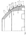
- Figure 1 shows a half section through an embodiment of a Screw according to the invention with a base body. 1 with a substantially hemispherical lateral surface 1.1, on which a two-start first thread 2 for cementless Anchoring the screw socket in the hipbone of a Patient is arranged.
- the section plane shown contains while the axis 3 of the screw.
- Inside shows the main body 1 a recess 1.2 for receiving a Inlays on, which is the later sliding surface for the femur anchored ball joint head of the hip joint prosthesis to Provides.
- the thread base 2.1 of the first thread 2 is located on the Lateral surface 1.1 of the main body 1, which in Figure 1 in the area the first thread 2 is shown in dashed lines.
- the tips 4 of the first thread 2 are substantially over the entire length of the first thread 2 on a for Lateral surface 1.1 parallel - dash-dotted in Figure 1 shown - surface 5.
- the tips 4 of the first thread 2 thus have substantially over the entire length of the first thread 2 each have the same vertical distance to the lateral surface 1.1, so that adjacent flanks 6.1 and 6.2 of the first thread 2 each have the same edge height exhibit. Only at the beginning and at the outlet of the first thread 2, both not shown in Figure 1 are, the tips 4 extend over each one relatively short section between the lateral surface 1.1 and the first surface 5.
- the thread root 2.1 essentially filling second Thread 7 arranged, whose slope is equal to the slope of the first thread 2 is. Since the first thread 2 sauten is executed, the edge 6.1 belongs to the first thread the first thread 2 and the distal adjacent Flank 6.2 to the second thread of the first thread. 2 Between the two flanks 6.1 and 6.2 of the first thread are three threads 7.1, 7.2 and 7.3 of the second Thread 7 arranged. Overall, the second thread has 7 due to the Zwetician the first thread 2 the twice the number of turns, that is six threads.
- the tips 8 of the second thread 7 are substantially over the entire length of the second thread 7 on a parallel to the lateral surface 1.1 - dash-dotted two in Figure 1 illustrated - second surface 9.
- the tips 8 of the second thread 7 thus have substantially over the entire length of the second thread 7 each the same vertical distance to the lateral surface 1.1, so that adjacent flanks 7.1 and 7.2 of the second thread. 7 each have the same edge height. Only at the beginning and at the outlet of the second thread 7, both in FIG. 1 are not shown, the tips 8 extend, Similar to the first thread 2, each one relatively short section between the lateral surface 1.1 and the second surface 9.
- flank height of flanks 7.1, 7.2 and 7.3 of the second Thread 7 is about half less than the flank height the adjacent flanks 6.1 and 6.2 of the first Thread 2. This is a significant weakening of the Hipbone into which the screw is screwed in the area between the two adjacent flanks 6.1 and 6.2 of the first thread 2 through the second thread. 7 avoided.
- the gap in the thread root 2.1 between the two flanks 6.1 and 6.2 of the first thread 2 is by between the two flanks 6.1 and 6.2 of the first Thread 2 arranged three threads 7.1, 7.2 and 7.3 the second thread 7 divided substantially uniformly, so that in addition a favorable introduction of force in the Hip bone over the first thread 2 and the second thread 7 is ensured.
- Both threads 2 and 7 are in a known manner by each Milled cuts provided over the thread length designed self-tapping, which makes a particularly good flat mating between the thread flanks and the Hip bone results, in which screwed the screw later becomes. It is understood, however, that in others Versions only one of the two threads self-tapping or possibly neither thread self-tapping is performed, with the corresponding Counter thread then with appropriate cutting tools before screwing the screw in the hip bone must be cut.
- the distal flanks 6.1 and the proximal flanks 6.2 of the first thread 2 and the distal flanks 10.1 and the proximal flanks 10.2 of the second thread run in the axial section of the screw shown in Figure 1 inclined by 80 ° to the axis 3 of the screw.
- the distal flanks 6.1 of the first thread 2 and the distal Flanks 10.1 of the second thread 7 run parallel to each other, wherein they are shown in FIG Axial section clockwise by 80 ° to axis 3 are inclined.
- the proximal flanks 6.2 of the first thread 2 and the proximal flanks 10.2 of the second thread 7 also run parallel to each other, where they in the axial section shown in Figure 1 respectively clockwise by 80 ° to the axis 3 are inclined.
- the transition region 11 in the thread root 2.1 between each two adjacent thread flanks is, as here the example the distal flank 6.1 of the first thread 2 and the proximal flank 10.2 of the first thread 7.1 of the second thread 7 shown, circular arc-shaped.
- the radius of curvature of the transition region 11 corresponds while half the flank height of the second thread 7.
- the Transition region 11 opens in each case tangentially in the distal flank 6.1 of the first thread 2 and the proximal Flank 10.2 of the first thread 7.1 of the second thread 7th
- first Thread a molded on the base body 1 circumferential Paragraph 12 during a first sub-step with a first Cutter 13 and a second cutter 14 processed.
- first cutter simultaneously generates the distal flank 6.1 of the first thread 2 and the proximal edge 10.2 of the distal flank 6.1 distally adjacent first thread turn 7.1 of the - indicated by dashed lines in Figure 2 - second thread 7.
- the second cutter generates at the same time the proximal flank 6.2 of the first thread 2 and the distal flank 10.1 of the proximal flank 6.2 proximal adjacent third thread 7.3 of the second thread 7. It is understood that instead of milling cutters but Other tools, such as lathe or but also grinding wheels or the like can be used can.
- Cutters 13 and 14 are here as disc-shaped profile cutter formed with identical tool geometry.
- the Cutting edges 13.1 and 14.1 of the first cutter 13 and des second cutter 14 thereby produce each distal flanks of the first thread 2 and the second thread 7, respectively the cutting edges 13.2 and 14.2 each proximal flanks produce the first thread 2 and the second thread 7.
- the cutting edges 13.1 and 14.1 of the first milling cutter 13 or of the second cutter 14 extend in the shown Axial section respectively according to the inclination of the distal Flanks of the first thread 2 and the second thread. 7 inclined to the screw pan axis 3.
- the cutting edges 13.2 and 14.2 again run in the axial section respectively shown according to the inclination proximal flanks of the first Thread 2 and the second thread 7th
- transition region 11 between adjacent thread flanks 6.1 and 10.2 generating section 13.3 of the milling cutter 13 is according to the contour of the transition area 11 also formed a circular arc. The same applies to section 14.3 of the second cutter 14.
- first cutter 13 and the second cutter 14 For generating mutually parallel distal thread flanks of the first and second threads and parallel to each other proximal thread flanks of the first and second threads become the first cutter 13 and the second cutter 14 in the section plane shown on a to the lateral surface 1.1 parallel trajectory parallel shifted, so that their Cutting edges 13.1 or 13.2 and 14.1 or 14.2 so always enclose the same angle with the cup axis 3.
- the screw is rotated about its axis 3, so that it is processed on its entire circumference.
- the Trajectory of the first cutter 13 and second cutter 14th runs in such a way that after a full revolution of the Screw pan around the screw pan axis 3 of the - in 2 dashed lines - positions 13 'and 14 'shifted in the position shown 13 and 14 in parallel were.
- first cutter 13 and the second cutter 14 each guided so that the circular arc Section 13.3 of the milling cutter 13 and the circular arc Section 14.3 of the second cutter 14 tangentially is guided to the lateral surface 1.1 of the base body 1, d. H. that the respective section 13.3 or 14.3, the lateral surface 1.1 of the body in each case touched in one point.
- the cutters 13 and 14 become so guided that the tips 4 of the first thread 2 on the lie to the lateral surface 1.1 parallel first surface 5.
- the axes of rotation of the first and second cutters 13 and 14 run - which in Figure 1 for reasons of clarity not shown - according to the thread pitch of the first and second threads 2 and 7 to the cutting plane inclined, wherein they are perpendicular to the cutting plane Lie flat.
- first thread 2 is double-threaded, is to simultaneous production of flanks 6.3 and 6.4 during of the first sub-step - not shown in Figure 2 with respect to the axis 3 to the first and second Cutter 13 and 14 symmetrically arranged and trained, provided second pair of milling cutters. It goes without saying, that in other variants for the production of Flanks 6.3 and 6.4 also in a second pass during the first part of the step, the cutter 13 and 14 used could become.
- a third mill 15 which has the same tool geometry like the first and second cutters 13 and 14 having.
- the angular position of the cutting edges 15.1 or 15.2 of the third cutter 15 with respect to the axis 3 corresponds the described angular position of the cutting edges 13.1 or 13.2 of the first milling cutter 13. The same applies to the orientation of the cutter axis to the cutting plane.
- the third cutter simultaneously produces the distal flank 10.3 of the first thread 7.1 of the second thread. 7 and the proximal flank 10.4 of the flank 10.3 distal adjacent second thread 7.2 of the second thread 7. It is understood that also here instead of the milling cutter another tool, such as a lathe tool or even a grinding wheel or the like can be used.
- the operation of the third cutter 15 during the second section quizes equal to that of the first cutter 13th during the first step.
- the third cutter 15 is also on a parallel to the lateral surface 1.1 Path by parallel displacement in the section plane shown method.
- the cutter 15 is guided so that the Tips 8 of the second thread 7 on the to the lateral surface 1.1 parallel first surface 9 are.
- FIG. 4 shows a partial axial section through another one Execution of the screw according to the invention. Construction and Production of this variant correspond essentially the embodiment described in Figures 1 to 3, see that here only on the differences to this version to be received.
- the first thread 2 substantially corresponds to the first Thread of Figure 1, while the second thread 7 "a significantly lower edge height than the second Thread of Figure 1.
- the flank height of the second thread 7 correlates to about one sixth of the flank height of the first thread 2 ".
- the second thread 7 is shown Example not self-tapping.
- the Flank height of the second thread 7 is so small and the thread teeth are so slim that the flanks of the second thread 7 "when screwing the screw in a recess in the hip bone possibly without problems be pressed into the hipbone.
- the contact between the thread crests 8 "and the hip bone stimulates this then to grow, so that bone tissue in the threads of the second thread 7 "grows.
- the first tool 13 "or the second tool 14” points at its respective tip section 13.3 “or 14.3” one larger cutting edge radius than the third tool 15 "at its top section 15.3".
Landscapes
- Health & Medical Sciences (AREA)
- Orthopedic Medicine & Surgery (AREA)
- Engineering & Computer Science (AREA)
- Heart & Thoracic Surgery (AREA)
- Life Sciences & Earth Sciences (AREA)
- Oral & Maxillofacial Surgery (AREA)
- Transplantation (AREA)
- Biomedical Technology (AREA)
- Mechanical Engineering (AREA)
- Vascular Medicine (AREA)
- Cardiology (AREA)
- Animal Behavior & Ethology (AREA)
- General Health & Medical Sciences (AREA)
- Public Health (AREA)
- Veterinary Medicine (AREA)
- Prostheses (AREA)
- Surgical Instruments (AREA)
Description
- Figur 1
- einen Halbschnitt eines bevorzugten Ausführungsbeispiels der Erfindung;
- Figur 2
- den Schnitt aus Figur 1 während des ersten Teilschrittes des erfindungsgemäßen Verfahrens;
- Figur 3
- den Schnitt aus Figur 1 während des zweiten Teilschrittes des erfindungsgemäßen Verfahrens;
- Figur 4
- einen Teilschnitt durch eine weitere Ausführung der erfindungsgemäßen Schraubpfanne.
Claims (22)
- Schraubpfanne für eine Hüftgelenksprothese mit einem Grundkörper (1; 1''), der eine zur Pfannenachse (3) im wesentlichen rotationssymmetrische, insbesondere im wesentlichen halbkugelförmige, ellipsoidförmige oder konische Mantelfläche (1.1; 1.1") aufweist, und einem auf der Außenseite des Grundkörpers (1; 1") angeordneten ersten Gewinde (2; 2") zur Verankerung der Schraubpfanne im Hüftknochen, dessen Gewindegrund (2.1; 2.1") im wesentlichen auf der Mantelfläche (1.1; 1.1'') des Grundkörpers (1; 1") liegt, wobei
zwischen benachbarten Flanken (6.1, 6.2) des ersten Gewindes (2; 2'') wenigstens ein den Gewindegrund (2.1; 2.1") des ersten Gewindes (2; 2") im wesentlichen ausfüllendes zweites Gewinde (7; 7'') vorgesehen ist, dessen lokale Flankenhöhe senkrecht zur Mantelfläche (1.1; 1.1") über im wesentlichen die gesamte Länge des zweiten Gewindes (7; 7'') wesentlich geringer ist als die lokale Flankenhöhe der beiden benachbarten Flanken (6.1, 6.2) oder der kürzeren der beiden benachbarten Flanken (6.1, 6.2) des ersten Gewindes (2; 2"),
dadurch gekennzeichnet daß das erste Gewinde (2; 2") und/oder das zweite Gewinde (7; 7") mehrgängig ausgebildet ist bzw. sind und die Gangzahl des zweiten Gewindes (7; 7") einem ganzzahligen Vielfachen der Gangzahl des ersten Gewindes (2; 2") entspricht. - Schraubpfanne nach Anspruch 1, dadurch gekennzeichnet, daß die lokale Flankenhöhe des zweiten Gewindes (2; 2") um wenigstens die Hälfte, vorzugsweise wenigstens zwei Drittel, geringer ist als die lokale Flankenhöhe der beiden benachbarten Flanken (6.1, 6.2) oder der kürzeren der beiden benachbarten Flanken (6.1, 6.2) des ersten Gewindes (7; 7").
- Schraubpfanne nach Anspruch 1 oder 2, dadurch gekennzeichnet, daß das erste Gewinde (2; 2") und/oder das zweite Gewinde (7; 7'') selbstschneidend ausgebildet ist.
- Schraubpfanne nach einem der vorhergehenden Ansprüche, dadurch gekennzeichnet, daß das erste Gewinde (2; 2") zweigängig und das zweite Gewinde (7; 7'') wenigstens viergängig ausgebildet ist.
- Schraubpfanne nach einem der vorhergehenden Ansprüche, dadurch gekennzeichnet, daß das zweite Gewinde (7; 7'') derart ausgebildet und angeordnet ist, daß der Zwischenraum im Gewindegrund (2.1; 2.1") zwischen zwei Flanken (6.1, 6.2) des ersten Gewindes im Axialschnitt der Schraubpfanne durch den zwischen den zwei Flanken (6.1, 6.2) des ersten Gewindes (2; 2") angeordneten Gewindegang des zweiten Gewindes (7; 7") oder die zwischen den zwei Flanken (6.1, 6.2) des ersten Gewindes angeordneten Gewindegänge des zweiten Gewindes (7; 7'') im wesentlichen gleichmäßig unterteilt ist.
- Schraubpfanne nach einem der vorhergehenden Ansprüche, dadurch gekennzeichnet, daß der Übergangsbereich (11; 11.1", 11.2", 11.3") zwischen zwei Flanken (6.1, 10.2; 10.3, 10.4; 10.1, 6.2) im Gewindegrund (2.1; 2.1") im Axialschnitt der Schraubpfanne im wesentlichen bogenförmig ausgebildet ist.
- Schraubpfanne nach Anspruch 6, dadurch gekennzeichnet, daß der Übergangsbereich (11) im Axialschnitt der Schraubpfanne im wesentlichen kreisbogenförmig ausgebildet ist, wobei der Übergangsbereich (11) jeweils im wesentlichen tangential in eine der beiden Flanken (6.1, 10.2; 10.3, 10.4; 10.1, 6.2) mündet und einen Krümmungsradius aufweist, der höchstens im wesentlichen der halben Flankenhöhe des zweiten Gewindes (7) entspricht.
- Schraubpfanne nach einem der vorhergehenden Ansprüche, dadurch gekennzeichnet, daß die distalen Flanken (6.1, 6.3) des ersten Gewindes (2; 2") und die distalen Flanken (10.1, 10.3, 10.5, 10.7, 10.9) des zweiten Gewindes (7; 7") im Axialschnitt der Schraubpfanne zur Achse (3) der Schraubpfanne um einen Winkel von im wesentlichen 70° bis 90°, vorzugsweise 75° bis 85°, geneigt verlaufen sowie die proximalen Flanken (6.2, 6.4) des ersten Gewindes (2; 2") und die proximalen Flanken (10.2, 10.4, 10.6, 10.8, 10.10) des zweiten Gewindes (7; 7") im Axialschnitt der Schraubpfanne zur Achse (3) der Schraubpfanne um einen Winkel von im wesentlichen 70° bis 90°, vorzugsweise 75° bis 85°, geneigt verlaufen.
- Schraubpfanne nach Anspruch 8, dadurch gekennzeichnet, daß die distalen und proximalen Flanken (6.1, 6.3; 6.2, 6.4) des ersten Gewindes (2; 2") im Axialschnitt der Schraubpfanne zur Achse (3) der Schraubpfanne um betragsmäßig im wesentlichen denselben Winkel geneigt verlaufen sowie die distalen und proximalen Flanken (10.1, 10.3, 10.5, 10.7, 10.9; 10.2, 10.4, 10.6, 10.8, 10.10) des zweiten Gewindes (7; 7'') im Axialschnitt der Schraubpfanne zur Achse (3) der Schraubpfanne um betragsmäßig im wesentlichen denselben Winkel geneigt verlaufen.
- Schraubpfanne nach Anspruch 8 oder 9, dadurch gekennzeichnet, daß die distalen Flanken (6.1, 6.3) des ersten Gewindes (2) und die distalen Flanken (10.1, 10.3, 10.5, 10.7, 10.9) des zweiten Gewindes (7) sowie die proximalen Flanken (6.2, 6.4) des ersten Gewindes (2) unddie proximalen Flanken (10.2, 10.4, 10.6, 10.8, 10.10) des zweiten Gewindes (7) zueinander im wesentlichen parallel verlaufen.
- Schraubpfanne nach einem der vorhergehenden Ansprüche, dadurch gekennzeichnet, daß die Spitzen (4) des ersten Gewindes (2; 2") über im wesentlichen die gesamte Länge des ersten Gewindes (2; 2") auf einer zur Mantelfläche (1.1; 1.1'') des Grundkörpers (1; 1'') im wesentlichen parallelen ersten Fläche (5; 5") liegen und/oder die Spitzen (8) des zweiten Gewindes (7; 7") über im wesentlichen die gesamte Länge des zweiten Gewindes (7; 7'') auf einer zur Mantelfläche (1.1; 1.1'') des Grundkörpers (1; 1'') im wesentlichen parallelen zweiten Fläche (9; 9") liegen.
- Schraubpfanne nach Anspruch 11, dadurch gekennzeichnet, daß die Mantelfläche (1.1; 1.1'') im wesentlichen halbkugelförmig ist.
- Verfahren zur spanenden Herstellung einer Schraubpfanne nach einem der vorhergehenden Ansprüche, dadurch gekennzeichnet, daß die Schraubpfanne in einem ersten Teilschritt zur Erzeugung des ersten Gewindes (2; 2") mit wenigstens einem ersten Werkzeug (13; 13") und einem zweiten Werkzeug (14; 14") bearbeitet wird und während des ersten Teilschrittes oder in einem zweiten Teilschritt die restlichen Flanken (10.3, 10.4, 10.5, 10.6) des zweiten Gewindes (7; 7'') ausgebildet werden.
- Verfahren nach Anspruch 13, dadurch gekennzeichnet, daß das erste Werkzeug (13; 13") derart ausgebildet ist, daß es gleichzeitig die distale Flanke (6.1) des ersten Gewindes (2; 2") und die proximale Flanke (10.2) des distal benachbarten Abschnitts (7.1) des zweiten Gewindes (1; 1'') erzeugt, und das zweite Werkzeug (14; 14") derart ausgebildet ist, daß es gleichzeitig die proximale Flanke (6.2) des ersten Gewindes (2; 2") und die distale Flanke (10.1) des proximal benachbarten Abschnitts (7.3) des zweiten Gewindes (7; 7") erzeugt.
- Verfahren nach Anspruch 13 oder 14, dadurch gekenn zeichnen, daß die Schraubpfanne zur Herstellung der restlichen Flanken (10.3, 10.4, 10.5, 10.6) des zweiten Gewindes (7; 7'') während des ersten Teilschrittes mit wenigstens einem dritten Werkzeug (15; 15") bearbeitet wird, das derart ausgebildet ist, daß es gleichzeitig die proximale Flanke (10.4) eines ersten Abschnitts (7.2) des zweiten Gewindes (7; 7'') und die distale Flanke (10.3) des dem ersten Abschnitt (7.2) proximal benachbarten zweiten Abschnitts (7.1) des zweiten Gewindes (7; 7") erzeugt.
- Verfahren nach Anspruch 15, dadurch gekennzeichnet, daß die Werkzeuggeometrie des dritten Werkzeugs (15; 15") der Werkzeuggeometrie des ersten Werkzeugs (13; 13") oder des zweiten Werkzeugs (14; 14") entspricht.
- Verfahren nach Anspruch 13 oder 14, dadurch gekennzeichnet, daß die Schraubpfanne zur Herstellung der restlichen Flanken (10.3, 10.4, 10.5, 10.6) des zweiten Gewindes (7) während des zweiten Teilschrittes mit dem ersten Werkzeug (13) und/oder dem zweiten Werkzeug (14) derart bearbeitet wird, daß gleichzeitig die proximale Flanke (10.4) eines ersten Abschnitts (7.2) des zweiten Gewindes (7; 7'') und die distale Flanke (10.3) des dem ersten Abschnitt (7.2) proximal benachbarten zweiten Abschnitts (7.1) des zweiten Gewindes (7) erzeugt wird.
- Verfahren nach einem der Ansprüche 13 bis 17, dadurch gekennzeichnet, daß das erste und zweite Werkzeug (13, 14; 13", 14") im wesentlichen dieselbe Werkzeuggeometrie aufweisen.
- Verfahren nach einem der Ansprüche 13 bis 18, dadurch gekennzeichnet, daß die Werkzeuge (13, 14, 15; 13", 14", 15") bei der Bearbeitung der Schraubpfanne durch Parallelverschiebung auf einer zur Mantelfläche (1.1; 1.1") im wesentlichen parallelen Bahnkurve geführt werden.
- Verfahren nach einem der Ansprüche 13 bis 19, dadurch gekennzeichnet, daß der den Übergangsbereich (11) zwischen zwei Flanken (6.1, 10.2; 10.3, 10.4; 10.1, 6.2) im Gewindegrund (2.1; 2.1") erzeugende Abschnitt (13.3, 14.3, 15.3; 13.3", 14.3", 15.3") des jeweiligen Werkzeuges (13, 14, 15; 13", 14", 15") im Axialschnitt der Schraubpfanne im wesentlichen bogenförmig, insbesondere kreisbogenförmig, ausgebildet ist.
- Verfahren nach Anspruch 20, dadurch gekennzeichnet, daß der bogenförmig ausgebildete Abschnitt (13.3, 14.3, 15.3; 13.3", 14.3", 15.3") der Werkzeuge (13, 14, 15; 13", 14", 15") jeweils im wesentlichen tangential zur Mantelfläche (1.1; 1.1") geführt wird.
- Verfahren nach einem der Ansprüche 13 bis 21, dadurch gekennzeichnet, daß als Werkzeuge (13, 14, 15; 13", 14", 15'') entsprechend ausgebildete Fräser und/oder Drehmeißel verwendet werden.
Applications Claiming Priority (2)
| Application Number | Priority Date | Filing Date | Title |
|---|---|---|---|
| DE19812874A DE19812874A1 (de) | 1998-03-17 | 1998-03-17 | Schraubpfanne |
| DE19812874 | 1998-03-17 |
Publications (3)
| Publication Number | Publication Date |
|---|---|
| EP0943304A2 EP0943304A2 (de) | 1999-09-22 |
| EP0943304A3 EP0943304A3 (de) | 2000-10-11 |
| EP0943304B1 true EP0943304B1 (de) | 2005-03-02 |
Family
ID=7862099
Family Applications (1)
| Application Number | Title | Priority Date | Filing Date |
|---|---|---|---|
| EP98250441A Expired - Lifetime EP0943304B1 (de) | 1998-03-17 | 1998-12-17 | Schraubpfanne für eine Hüftgelenksprothese |
Country Status (2)
| Country | Link |
|---|---|
| EP (1) | EP0943304B1 (de) |
| DE (2) | DE19812874A1 (de) |
Families Citing this family (3)
| Publication number | Priority date | Publication date | Assignee | Title |
|---|---|---|---|---|
| CH1411869H1 (de) | 2001-07-31 | 2018-08-15 | Stemcup Medical Products Ag Aargauerstrasse 180 | |
| CH699592B1 (de) | 2008-09-23 | 2012-04-30 | Stemcup Medical Products Ag | Einschraubpfanne für ein Hüftgelenkimplantat. |
| CN111513894A (zh) * | 2019-02-03 | 2020-08-11 | 北京纳通医学科技研究院有限公司 | 髋臼杯 |
Family Cites Families (6)
| Publication number | Priority date | Publication date | Assignee | Title |
|---|---|---|---|---|
| FR2610512B1 (fr) * | 1987-02-06 | 1997-01-24 | Cuilleron J | Procede et moyens d'ancrage d'elements d'implants visses dans les tissus osseux et les elements d'implants obtenus |
| FR2639822B1 (fr) * | 1988-12-07 | 1997-04-04 | Implants Instr Ch Fab | Anneau visse dans les cotyles osseux |
| DE4031926A1 (de) * | 1990-10-09 | 1992-04-16 | Gerd Hoermansdoerfer | Einschraubbare hueftgelenkpfanne und verfahren zu deren herstellung |
| DE9014542U1 (de) * | 1990-10-20 | 1991-01-03 | Howmedica GmbH, 2314 Schönkirchen | Schalenelement zur Aufnahme einer Gelenkendoprothese |
| DE4400001A1 (de) * | 1994-01-02 | 1995-07-06 | Gerd Hoermansdoerfer | Verfahren zur Herstellung eines Gewindes mit veränderlich modifzierbarem Gewindeprofil und bevorzugte Anwendung des Verfahrens |
| DE19514455C1 (de) * | 1995-04-19 | 1996-11-14 | Werner Scholz | Endoprothese, insbesondere künstliche Hüftgelenkpfanne |
-
1998
- 1998-03-17 DE DE19812874A patent/DE19812874A1/de not_active Ceased
- 1998-12-17 EP EP98250441A patent/EP0943304B1/de not_active Expired - Lifetime
- 1998-12-17 DE DE59812613T patent/DE59812613D1/de not_active Expired - Lifetime
Also Published As
| Publication number | Publication date |
|---|---|
| EP0943304A3 (de) | 2000-10-11 |
| DE19812874A1 (de) | 1999-09-23 |
| DE59812613D1 (de) | 2005-04-07 |
| EP0943304A2 (de) | 1999-09-22 |
Similar Documents
| Publication | Publication Date | Title |
|---|---|---|
| DE69319204T2 (de) | Verankerungselement zum Halten von Gelenksprothesen für ein wiederhergestelltes Gelenk | |
| DE3752049T2 (de) | Modulsystem zum Fixieren des Femur | |
| EP0898470B1 (de) | Hüftgelenkpfanne mit spezialgewinde | |
| EP1100396B1 (de) | Implantat zum halten und/oder bilden eines zahnersatzes oder eines künstlichen fingergelenks | |
| DE3421056A1 (de) | Kieferimplantat zur aufnahme eines zahnersatztraegers | |
| DE102012105873A1 (de) | Zahnimplantat | |
| EP0622056A2 (de) | Implantierbares Verankerungsorgan zur Aufnahme von Prothesen u.dgl. | |
| EP0318679B2 (de) | Endoprothese für eine Hüftgelenkspfanne | |
| EP0069252A1 (de) | Gelenkendoprothese | |
| EP0578345B1 (de) | Hüftpfannenendoprothese | |
| DE69818638T2 (de) | Zahnmedizinisches implantat | |
| EP1326551B1 (de) | Implantat mit rillenstruktur | |
| EP0943304B1 (de) | Schraubpfanne für eine Hüftgelenksprothese | |
| EP0687165B1 (de) | Verfahren zur herstellung eines gewindes mit veränderlich modifizierbarem gewindeprofil und anwendung des verfahrens | |
| EP1411869B1 (de) | Künstliche gelenkpfanne | |
| DE60116846T2 (de) | Verfahren zur Herstellung einer Verzahnung auf einer Oberfläche | |
| EP0480551B1 (de) | Einschraubbare Hüftgelenkpfanne und Verfahren zu deren Herstellung | |
| EP1915102A2 (de) | Werkzeuge zum herstellen und vorbereiten einer bohrung zur aufnahme von zahnimplantaten und entsprechendes zahnimplantat | |
| EP1809208B1 (de) | Einschraubkörper mit sich änderndem gewindeprofil und verfahren zu dessen herstellung | |
| DE3804310C1 (de) | ||
| EP0667134B1 (de) | Orthopädisches Knochen-Implantat | |
| EP4285861B1 (de) | Dentalimplantat | |
| EP4231946A1 (de) | Schraubenelement optimiert für den 3d-druck | |
| DE602006000956T2 (de) | Prothese mit selbststanzenden Erhöhungen | |
| EP0945108A2 (de) | Endoprothese mit einem Verankerungsschaft |
Legal Events
| Date | Code | Title | Description |
|---|---|---|---|
| PUAI | Public reference made under article 153(3) epc to a published international application that has entered the european phase |
Free format text: ORIGINAL CODE: 0009012 |
|
| AK | Designated contracting states |
Kind code of ref document: A2 Designated state(s): DE ES FR GB IT |
|
| AX | Request for extension of the european patent |
Free format text: AL;LT;LV;MK;RO;SI |
|
| PUAL | Search report despatched |
Free format text: ORIGINAL CODE: 0009013 |
|
| AK | Designated contracting states |
Kind code of ref document: A3 Designated state(s): AT BE CH CY DE DK ES FI FR GB GR IE IT LI LU MC NL PT SE |
|
| AX | Request for extension of the european patent |
Free format text: AL;LT;LV;MK;RO;SI |
|
| RIC1 | Information provided on ipc code assigned before grant |
Free format text: 7A 61F 2/34 A, 7B 23G 5/06 B |
|
| 17P | Request for examination filed |
Effective date: 20010403 |
|
| AKX | Designation fees paid |
Free format text: DE ES FR GB IT |
|
| 17Q | First examination report despatched |
Effective date: 20030826 |
|
| GRAP | Despatch of communication of intention to grant a patent |
Free format text: ORIGINAL CODE: EPIDOSNIGR1 |
|
| GRAS | Grant fee paid |
Free format text: ORIGINAL CODE: EPIDOSNIGR3 |
|
| GRAA | (expected) grant |
Free format text: ORIGINAL CODE: 0009210 |
|
| AK | Designated contracting states |
Kind code of ref document: B1 Designated state(s): DE ES FR GB IT |
|
| PG25 | Lapsed in a contracting state [announced via postgrant information from national office to epo] |
Ref country code: IT Free format text: LAPSE BECAUSE OF FAILURE TO SUBMIT A TRANSLATION OF THE DESCRIPTION OR TO PAY THE FEE WITHIN THE PRE;WARNING: LAPSES OF ITALIAN PATENTS WITH EFFECTIVE DATE BEFORE 2007 MAY HAVE OCCURRED AT ANY TIME BEFORE 2007. THE CORRECT EFFECTIVE DATE MAY BE DIFFERENT FROM THE ONE RECORDED.SCRIBED TIME-LIMIT Effective date: 20050302 Ref country code: GB Free format text: LAPSE BECAUSE OF FAILURE TO SUBMIT A TRANSLATION OF THE DESCRIPTION OR TO PAY THE FEE WITHIN THE PRESCRIBED TIME-LIMIT Effective date: 20050302 Ref country code: FR Free format text: LAPSE BECAUSE OF NON-PAYMENT OF DUE FEES Effective date: 20050302 |
|
| REG | Reference to a national code |
Ref country code: GB Ref legal event code: FG4D Free format text: NOT ENGLISH |
|
| REF | Corresponds to: |
Ref document number: 59812613 Country of ref document: DE Date of ref document: 20050407 Kind code of ref document: P |
|
| PG25 | Lapsed in a contracting state [announced via postgrant information from national office to epo] |
Ref country code: ES Free format text: LAPSE BECAUSE OF FAILURE TO SUBMIT A TRANSLATION OF THE DESCRIPTION OR TO PAY THE FEE WITHIN THE PRESCRIBED TIME-LIMIT Effective date: 20050613 |
|
| GBV | Gb: ep patent (uk) treated as always having been void in accordance with gb section 77(7)/1977 [no translation filed] |
Effective date: 20050302 |
|
| PLBE | No opposition filed within time limit |
Free format text: ORIGINAL CODE: 0009261 |
|
| STAA | Information on the status of an ep patent application or granted ep patent |
Free format text: STATUS: NO OPPOSITION FILED WITHIN TIME LIMIT |
|
| 26N | No opposition filed |
Effective date: 20051205 |
|
| EN | Fr: translation not filed | ||
| PGFP | Annual fee paid to national office [announced via postgrant information from national office to epo] |
Ref country code: DE Payment date: 20101115 Year of fee payment: 13 |
|
| REG | Reference to a national code |
Ref country code: DE Ref legal event code: R119 Ref document number: 59812613 Country of ref document: DE Effective date: 20120703 |
|
| PG25 | Lapsed in a contracting state [announced via postgrant information from national office to epo] |
Ref country code: DE Free format text: LAPSE BECAUSE OF NON-PAYMENT OF DUE FEES Effective date: 20120703 |