EP0943304B1 - Threaded acetabular cup for a hip joint prosthesis - Google Patents
Threaded acetabular cup for a hip joint prosthesis Download PDFInfo
- Publication number
- EP0943304B1 EP0943304B1 EP98250441A EP98250441A EP0943304B1 EP 0943304 B1 EP0943304 B1 EP 0943304B1 EP 98250441 A EP98250441 A EP 98250441A EP 98250441 A EP98250441 A EP 98250441A EP 0943304 B1 EP0943304 B1 EP 0943304B1
- Authority
- EP
- European Patent Office
- Prior art keywords
- thread
- flanks
- acetabular cup
- essentially
- tool
- Prior art date
- Legal status (The legal status is an assumption and is not a legal conclusion. Google has not performed a legal analysis and makes no representation as to the accuracy of the status listed.)
- Expired - Lifetime
Links
Images


Classifications
-
- A—HUMAN NECESSITIES
- A61—MEDICAL OR VETERINARY SCIENCE; HYGIENE
- A61F—FILTERS IMPLANTABLE INTO BLOOD VESSELS; PROSTHESES; DEVICES PROVIDING PATENCY TO, OR PREVENTING COLLAPSING OF, TUBULAR STRUCTURES OF THE BODY, e.g. STENTS; ORTHOPAEDIC, NURSING OR CONTRACEPTIVE DEVICES; FOMENTATION; TREATMENT OR PROTECTION OF EYES OR EARS; BANDAGES, DRESSINGS OR ABSORBENT PADS; FIRST-AID KITS
- A61F2/00—Filters implantable into blood vessels; Prostheses, i.e. artificial substitutes or replacements for parts of the body; Appliances for connecting them with the body; Devices providing patency to, or preventing collapsing of, tubular structures of the body, e.g. stents
- A61F2/02—Prostheses implantable into the body
- A61F2/30—Joints
- A61F2/32—Joints for the hip
- A61F2/34—Acetabular cups
-
- B—PERFORMING OPERATIONS; TRANSPORTING
- B23—MACHINE TOOLS; METAL-WORKING NOT OTHERWISE PROVIDED FOR
- B23G—THREAD CUTTING; WORKING OF SCREWS, BOLT HEADS, OR NUTS, IN CONJUNCTION THEREWITH
- B23G5/00—Thread-cutting tools; Die-heads
- B23G5/02—Thread-cutting tools; Die-heads without means for adjustment
- B23G5/06—Taps
-
- A—HUMAN NECESSITIES
- A61—MEDICAL OR VETERINARY SCIENCE; HYGIENE
- A61F—FILTERS IMPLANTABLE INTO BLOOD VESSELS; PROSTHESES; DEVICES PROVIDING PATENCY TO, OR PREVENTING COLLAPSING OF, TUBULAR STRUCTURES OF THE BODY, e.g. STENTS; ORTHOPAEDIC, NURSING OR CONTRACEPTIVE DEVICES; FOMENTATION; TREATMENT OR PROTECTION OF EYES OR EARS; BANDAGES, DRESSINGS OR ABSORBENT PADS; FIRST-AID KITS
- A61F2/00—Filters implantable into blood vessels; Prostheses, i.e. artificial substitutes or replacements for parts of the body; Appliances for connecting them with the body; Devices providing patency to, or preventing collapsing of, tubular structures of the body, e.g. stents
- A61F2/02—Prostheses implantable into the body
- A61F2/30—Joints
- A61F2/3094—Designing or manufacturing processes
-
- A—HUMAN NECESSITIES
- A61—MEDICAL OR VETERINARY SCIENCE; HYGIENE
- A61F—FILTERS IMPLANTABLE INTO BLOOD VESSELS; PROSTHESES; DEVICES PROVIDING PATENCY TO, OR PREVENTING COLLAPSING OF, TUBULAR STRUCTURES OF THE BODY, e.g. STENTS; ORTHOPAEDIC, NURSING OR CONTRACEPTIVE DEVICES; FOMENTATION; TREATMENT OR PROTECTION OF EYES OR EARS; BANDAGES, DRESSINGS OR ABSORBENT PADS; FIRST-AID KITS
- A61F2/00—Filters implantable into blood vessels; Prostheses, i.e. artificial substitutes or replacements for parts of the body; Appliances for connecting them with the body; Devices providing patency to, or preventing collapsing of, tubular structures of the body, e.g. stents
- A61F2/02—Prostheses implantable into the body
- A61F2/30—Joints
- A61F2002/30001—Additional features of subject-matter classified in A61F2/28, A61F2/30 and subgroups thereof
- A61F2002/30316—The prosthesis having different structural features at different locations within the same prosthesis; Connections between prosthetic parts; Special structural features of bone or joint prostheses not otherwise provided for
- A61F2002/30317—The prosthesis having different structural features at different locations within the same prosthesis
- A61F2002/30326—The prosthesis having different structural features at different locations within the same prosthesis differing in height or in length
-
- A—HUMAN NECESSITIES
- A61—MEDICAL OR VETERINARY SCIENCE; HYGIENE
- A61F—FILTERS IMPLANTABLE INTO BLOOD VESSELS; PROSTHESES; DEVICES PROVIDING PATENCY TO, OR PREVENTING COLLAPSING OF, TUBULAR STRUCTURES OF THE BODY, e.g. STENTS; ORTHOPAEDIC, NURSING OR CONTRACEPTIVE DEVICES; FOMENTATION; TREATMENT OR PROTECTION OF EYES OR EARS; BANDAGES, DRESSINGS OR ABSORBENT PADS; FIRST-AID KITS
- A61F2/00—Filters implantable into blood vessels; Prostheses, i.e. artificial substitutes or replacements for parts of the body; Appliances for connecting them with the body; Devices providing patency to, or preventing collapsing of, tubular structures of the body, e.g. stents
- A61F2/02—Prostheses implantable into the body
- A61F2/30—Joints
- A61F2002/30001—Additional features of subject-matter classified in A61F2/28, A61F2/30 and subgroups thereof
- A61F2002/30316—The prosthesis having different structural features at different locations within the same prosthesis; Connections between prosthetic parts; Special structural features of bone or joint prostheses not otherwise provided for
- A61F2002/30329—Connections or couplings between prosthetic parts, e.g. between modular parts; Connecting elements
- A61F2002/30331—Connections or couplings between prosthetic parts, e.g. between modular parts; Connecting elements made by longitudinally pushing a protrusion into a complementarily-shaped recess, e.g. held by friction fit
- A61F2002/30332—Conically- or frustoconically-shaped protrusion and recess
- A61F2002/30345—Multiple conical connection, i.e. the protrusion and recess having several tapered sections of different complementary conicities
-
- A—HUMAN NECESSITIES
- A61—MEDICAL OR VETERINARY SCIENCE; HYGIENE
- A61F—FILTERS IMPLANTABLE INTO BLOOD VESSELS; PROSTHESES; DEVICES PROVIDING PATENCY TO, OR PREVENTING COLLAPSING OF, TUBULAR STRUCTURES OF THE BODY, e.g. STENTS; ORTHOPAEDIC, NURSING OR CONTRACEPTIVE DEVICES; FOMENTATION; TREATMENT OR PROTECTION OF EYES OR EARS; BANDAGES, DRESSINGS OR ABSORBENT PADS; FIRST-AID KITS
- A61F2/00—Filters implantable into blood vessels; Prostheses, i.e. artificial substitutes or replacements for parts of the body; Appliances for connecting them with the body; Devices providing patency to, or preventing collapsing of, tubular structures of the body, e.g. stents
- A61F2/02—Prostheses implantable into the body
- A61F2/30—Joints
- A61F2/30767—Special external or bone-contacting surface, e.g. coating for improving bone ingrowth
- A61F2/30771—Special external or bone-contacting surface, e.g. coating for improving bone ingrowth applied in original prostheses, e.g. holes or grooves
- A61F2002/3085—Special external or bone-contacting surface, e.g. coating for improving bone ingrowth applied in original prostheses, e.g. holes or grooves with a threaded, e.g. self-tapping, bone-engaging surface, e.g. external surface
- A61F2002/30851—Multiple threadings
-
- A—HUMAN NECESSITIES
- A61—MEDICAL OR VETERINARY SCIENCE; HYGIENE
- A61F—FILTERS IMPLANTABLE INTO BLOOD VESSELS; PROSTHESES; DEVICES PROVIDING PATENCY TO, OR PREVENTING COLLAPSING OF, TUBULAR STRUCTURES OF THE BODY, e.g. STENTS; ORTHOPAEDIC, NURSING OR CONTRACEPTIVE DEVICES; FOMENTATION; TREATMENT OR PROTECTION OF EYES OR EARS; BANDAGES, DRESSINGS OR ABSORBENT PADS; FIRST-AID KITS
- A61F2/00—Filters implantable into blood vessels; Prostheses, i.e. artificial substitutes or replacements for parts of the body; Appliances for connecting them with the body; Devices providing patency to, or preventing collapsing of, tubular structures of the body, e.g. stents
- A61F2/02—Prostheses implantable into the body
- A61F2/30—Joints
- A61F2/30767—Special external or bone-contacting surface, e.g. coating for improving bone ingrowth
- A61F2/30771—Special external or bone-contacting surface, e.g. coating for improving bone ingrowth applied in original prostheses, e.g. holes or grooves
- A61F2002/3085—Special external or bone-contacting surface, e.g. coating for improving bone ingrowth applied in original prostheses, e.g. holes or grooves with a threaded, e.g. self-tapping, bone-engaging surface, e.g. external surface
- A61F2002/30864—Microthreads
-
- A—HUMAN NECESSITIES
- A61—MEDICAL OR VETERINARY SCIENCE; HYGIENE
- A61F—FILTERS IMPLANTABLE INTO BLOOD VESSELS; PROSTHESES; DEVICES PROVIDING PATENCY TO, OR PREVENTING COLLAPSING OF, TUBULAR STRUCTURES OF THE BODY, e.g. STENTS; ORTHOPAEDIC, NURSING OR CONTRACEPTIVE DEVICES; FOMENTATION; TREATMENT OR PROTECTION OF EYES OR EARS; BANDAGES, DRESSINGS OR ABSORBENT PADS; FIRST-AID KITS
- A61F2/00—Filters implantable into blood vessels; Prostheses, i.e. artificial substitutes or replacements for parts of the body; Appliances for connecting them with the body; Devices providing patency to, or preventing collapsing of, tubular structures of the body, e.g. stents
- A61F2/02—Prostheses implantable into the body
- A61F2/30—Joints
- A61F2/32—Joints for the hip
- A61F2/34—Acetabular cups
- A61F2002/3401—Acetabular cups with radial apertures, e.g. radial bores for receiving fixation screws
- A61F2002/3403—Polar aperture
-
- A—HUMAN NECESSITIES
- A61—MEDICAL OR VETERINARY SCIENCE; HYGIENE
- A61F—FILTERS IMPLANTABLE INTO BLOOD VESSELS; PROSTHESES; DEVICES PROVIDING PATENCY TO, OR PREVENTING COLLAPSING OF, TUBULAR STRUCTURES OF THE BODY, e.g. STENTS; ORTHOPAEDIC, NURSING OR CONTRACEPTIVE DEVICES; FOMENTATION; TREATMENT OR PROTECTION OF EYES OR EARS; BANDAGES, DRESSINGS OR ABSORBENT PADS; FIRST-AID KITS
- A61F2/00—Filters implantable into blood vessels; Prostheses, i.e. artificial substitutes or replacements for parts of the body; Appliances for connecting them with the body; Devices providing patency to, or preventing collapsing of, tubular structures of the body, e.g. stents
- A61F2/02—Prostheses implantable into the body
- A61F2/30—Joints
- A61F2/32—Joints for the hip
- A61F2/34—Acetabular cups
- A61F2002/3453—Acetabular cups having a non-hemispherical convex outer surface, e.g. quadric-shaped
- A61F2002/3456—Acetabular cups having a non-hemispherical convex outer surface, e.g. quadric-shaped ellipsoidal or having a flattened polar region
-
- A—HUMAN NECESSITIES
- A61—MEDICAL OR VETERINARY SCIENCE; HYGIENE
- A61F—FILTERS IMPLANTABLE INTO BLOOD VESSELS; PROSTHESES; DEVICES PROVIDING PATENCY TO, OR PREVENTING COLLAPSING OF, TUBULAR STRUCTURES OF THE BODY, e.g. STENTS; ORTHOPAEDIC, NURSING OR CONTRACEPTIVE DEVICES; FOMENTATION; TREATMENT OR PROTECTION OF EYES OR EARS; BANDAGES, DRESSINGS OR ABSORBENT PADS; FIRST-AID KITS
- A61F2/00—Filters implantable into blood vessels; Prostheses, i.e. artificial substitutes or replacements for parts of the body; Appliances for connecting them with the body; Devices providing patency to, or preventing collapsing of, tubular structures of the body, e.g. stents
- A61F2/02—Prostheses implantable into the body
- A61F2/30—Joints
- A61F2/32—Joints for the hip
- A61F2/34—Acetabular cups
- A61F2002/3453—Acetabular cups having a non-hemispherical convex outer surface, e.g. quadric-shaped
- A61F2002/3462—Acetabular cups having a non-hemispherical convex outer surface, e.g. quadric-shaped having a frustoconical external shape, e.g. entirely frustoconical
-
- A—HUMAN NECESSITIES
- A61—MEDICAL OR VETERINARY SCIENCE; HYGIENE
- A61F—FILTERS IMPLANTABLE INTO BLOOD VESSELS; PROSTHESES; DEVICES PROVIDING PATENCY TO, OR PREVENTING COLLAPSING OF, TUBULAR STRUCTURES OF THE BODY, e.g. STENTS; ORTHOPAEDIC, NURSING OR CONTRACEPTIVE DEVICES; FOMENTATION; TREATMENT OR PROTECTION OF EYES OR EARS; BANDAGES, DRESSINGS OR ABSORBENT PADS; FIRST-AID KITS
- A61F2220/00—Fixations or connections for prostheses classified in groups A61F2/00 - A61F2/26 or A61F2/82 or A61F9/00 or A61F11/00 or subgroups thereof
- A61F2220/0025—Connections or couplings between prosthetic parts, e.g. between modular parts; Connecting elements
- A61F2220/0033—Connections or couplings between prosthetic parts, e.g. between modular parts; Connecting elements made by longitudinally pushing a protrusion into a complementary-shaped recess, e.g. held by friction fit
-
- A—HUMAN NECESSITIES
- A61—MEDICAL OR VETERINARY SCIENCE; HYGIENE
- A61F—FILTERS IMPLANTABLE INTO BLOOD VESSELS; PROSTHESES; DEVICES PROVIDING PATENCY TO, OR PREVENTING COLLAPSING OF, TUBULAR STRUCTURES OF THE BODY, e.g. STENTS; ORTHOPAEDIC, NURSING OR CONTRACEPTIVE DEVICES; FOMENTATION; TREATMENT OR PROTECTION OF EYES OR EARS; BANDAGES, DRESSINGS OR ABSORBENT PADS; FIRST-AID KITS
- A61F2250/00—Special features of prostheses classified in groups A61F2/00 - A61F2/26 or A61F2/82 or A61F9/00 or A61F11/00 or subgroups thereof
- A61F2250/0014—Special features of prostheses classified in groups A61F2/00 - A61F2/26 or A61F2/82 or A61F9/00 or A61F11/00 or subgroups thereof having different values of a given property or geometrical feature, e.g. mechanical property or material property, at different locations within the same prosthesis
- A61F2250/0037—Special features of prostheses classified in groups A61F2/00 - A61F2/26 or A61F2/82 or A61F9/00 or A61F11/00 or subgroups thereof having different values of a given property or geometrical feature, e.g. mechanical property or material property, at different locations within the same prosthesis differing in height or in length
Definitions
- the invention relates to a screw socket for a hip joint prosthesis according to the preamble of claim 1 as well a process for their preparation.
- the European patent application discloses 0 480 551 A1 a generic spherical screw pan, in which the spherical contour of the main body in Thread base by a number in axial section to each other inclined extending partial surfaces approximated polygonzugartig is.
- the faces form at their respective impact an obtuse-angled roof edge.
- This screw thus also not full surface but only in the area of the roof edges on the hip bone.
- the spherical Contour of the main body by many inclined to each other To approximate partial areas as closely as possible, which however a significantly increased production cost is required.
- Document FR-A-2 610 512 discloses a threaded cup according to the preamble of claim 1.
- the invention is therefore based on the object, a To provide generic screw available, the the disadvantages mentioned or not at least in less Has dimensions, in particular with ease of manufacture the screw pan a uniform introduction the joint loads in the hip bone and a reliable Fixation ensures. Furthermore, the invention is the task is based on a manufacturing process for to specify such a screw.
- the task is, starting from a screw according to the preamble of claim 1, by the in the characterizing Part of claim 1 specified features solved.
- the invention includes the technical teaching that one a quick and easy to manufacture screw with good force introduction in the hip bone gets when on the outside of the main body of the screw between two adjacent flanks of the first thread at least a filling the thread root of the first thread second thread is provided, the local flank height perpendicular to the lateral surface of the body about substantially the entire length of the second thread essential is less than the local flank height of the two adjacent flanks of the first thread. Under local Flanken altar should here in the respective point of Thread measured perpendicular to the lateral surface of the body Distance of the thread crest to the lateral surface of the Basic body be understood.
- the local flank height of the second thread less than the local flank height of the shorter ones the two adjacent flanks.
- the slope of the second thread corresponds to reasons of easier production preferably the pitch of the first thread.
- the second thread arranged in the thread root of the first thread Thread is compared to the known threaded cups one increased contact area and better contact between the screw and the hip bone safely.
- Flank height of the second thread results in the improved Contact between screw cup and hip bone two possibly overlapping effects of the second Thread.
- the flank height of the second thread is so low chosen that ensures that the hip bone is not is significantly weakened by the second thread, like this would be the case, for example, if the flank height of the second thread approximately in the region of the flank height of first thread would be.
- a large amount of living hip bone tissue removed on the other hand would be the strength of the Hip bone due to the relatively short distance reduced between adjacent thread crests Stress cross section and the increased notch effect in the ground of the cut in the hip bone counter thread considerably reduced.
- the invention sufficiently low Flank height of the second thread causes as possible much living bone tissue is preserved and thus the mechanical properties of the bone in Einschraub Scheme to be preserved as much as possible.
- the local flank height of the second thread preferably chosen to be at least one third preferably at least half, is less than the local flank height of possibly shorter of two adjacent flanks of the first thread.
- the local edge height of the second thread preferably essentially less than 95% lower than the local flank height of possibly shorter of the two adjacent flanks of the first thread. It understands It is that the second thread on the one hand over his Length may have a varying edge height. On the other hand can also have adjacent passages of the second thread have different flank height, in particular can separated by the flanks of the first thread Gears of the second thread different flank height exhibit.
- the screw according to the invention may be in principle constructed in conventional manner threaded cups from a biocompatible material, in particular biocompatible Metal or a corresponding metal alloy, acting in the pan interior a recess for Receiving an inlay, for example made of plastic, etc., which then the sliding surface for the anchored in the femur Ball head of the artificial hip joint forms.
- a biocompatible material in particular biocompatible Metal or a corresponding metal alloy
- Screw is the first, alternatively or preferably in addition, the second thread formed self-tapping.
- the screw according to the invention is the first thread, alternatively or additionally the second thread formed more continuous, preferably the number of threads of the second thread an integer Multiples the number of turns of the first thread corresponds.
- the specified number of threads of the second thread as understood relative to a single second thread which is located at the bottom of the first thread and its gears to the individual passages of the first thread are arranged distributed. More preferably, that is first thread in a known manner slaughterhim and the second Thread is formed at least four.
- the terminology above is between two Flanks of the first thread in each case at least two flanks arranged the second thread. This will be a good and uniform filling of the thread of the first thread with a second thread sufficiently lower Flank height achieved.
- the transition region between two flanks in the thread root in the axial section of ringpfanne formed substantially arcuate, for example, elliptical or circular arc, whereby reduces the notch effect in the foot area of the thread teeth is.
- the transition region is essentially circular arc-shaped each being substantially tangential opens into one of the two flanks and a radius of curvature having at most substantially the half flank height of the second thread corresponds. Thanks designed this simple circular arc transition area on the one hand also this area of the first or second thread-generating portion of or Machining tools also very easy. So For example, if this area of the first or second thread-generating tool section at a Turning tool a simple also arcuate Cutting edge on.
- fferpfanne run the distal flanks of the first Thread and the distal flanks of the second thread in the Axial section of the screw socket to the axis of the screw socket at an angle of substantially 70 ° to 90 °, preferably 75 ° to 85 °, inclined.
- the proximal flanks of the first Thread and the proximal flanks of the second thread extend in axial section of the screw also at an angle of substantially 70 ° to 90 °, preferably 75 ° to 85 °, inclined to the axis of the screw. This results both in terms of strength the thread as well as the material pairing made of screw and bone a particularly favorable Slenderness of thread flanks.
- the distal and proximal extend Flanks of the first thread as well as the distal and proximal ones Flanks of the second thread in the axial section of the Screw socket to the axis of the screw to amount tilted at substantially the same angle.
- This advantage in terms of design and guide the thread-generating or the Tools increases even further, if preferably the distal flanks of the first thread and the distal ones Flanks of the second thread and the proximal flanks of the first thread and the proximal flanks of the second Thread to each other substantially parallel. It is for making the first and second threads then possible, one and the same tool geometry, in particular to use the same or the same tools.
- the rotationally symmetrical to the pan axis substantially Mantle surface of the body can essentially the Shape of a truncated cone, an ellipsoidal part or a Paraboloidmaschines have.
- the screw are characterized by a substantially hemispherical shell surface of the main body.
- These spherical cups approach the geometry of the joint of the healthy hip joint better than conical variants. They therefore advantageously require resection on the one hand a lesser amount of living bone tissue and have a similar to the healthy joint load application in the hip bones.
- the invention further relates to a method for machining Production of a screw according to the invention, in the screw in a first sub-step for generating of the first thread with at least a first one Tool and a second tool is edited.
- the remaining flanks of the second thread can in the substantially simultaneously during the first substep getting produced.
- their manufacture can also take place in a second sub-step.
- the first tool is preferably designed such that it simultaneously the distal flank of the first thread and the proximal edge of the distally adjacent portion of the second thread while the second tool so is formed so that it is at the same time the proximal Flank of the first thread and the distal flank of the generated proximal adjacent portion of the second thread.
- the production of the screw is designed doing so very fast and therefore cost, because the flanks of the first thread adjacent and facing Flanks of the second thread after production of the first Thread need not be further processed and In particular, no additional tool required for this is.
- the first thread has more than one turn, so it is done by appropriately sequential editing the pan body with the first and second tools or by simultaneously working with one of the number of gears corresponding number distributed over the pan circumference first and second tools made. Is this second thread thereby formed catchy, so omitted further processing of the second thread completely, since its proximal and distal flanks according to the invention already directly in the production of the first thread with the first and second tools.
- the Screw socket for the production of the remaining flanks of the second thread during the first substep with at least edited a third tool is designed so that it simultaneously the proximal flank of a first section of the second thread and the distal edge of the first section proximally adjacent second section of the second Thread generated.
- the mutually facing flanks adjacent Sections of the second thread are thus in one operation made with a third tool. If the second thread has more than two threads, so it becomes simultaneously with the processing by the first and second tool with a number of third tools edited, which reduced by one gear of the second thread corresponds. Indicates the second thread So three threads on, so are in this variant the first and second tools associated with two third tools.
- first thread is still more frequent, so is for the case essentially Simultaneous creation of the threads of the first thread each pair of first and second tool a corresponding Number of third tools assigned. at a two-speed first thread and a six-speed one second threads would be in the case of a substantially Simultaneous production of all threads two pairs each of a first, a second and two third Tools required, which then over the pan circumference are distributed.
- the tool geometry of the third tool of the tool geometry of the first tool or the second tool since thus the required Number of different tools and thus also the Production cost is reduced.
- the screw in view of the limited space at its periphery only with one limited number of tools simultaneously can be.
- the screw for Production of the remaining flanks of the second thread is the screw for Production of the remaining flanks of the second thread therefore during a second sub-step with appropriate edited third tools.
- the first and / or second tool as a third tool used, again here at the same time the proximal edge of a first portion of the second thread and the distal edge of the first section proximal adjacent second portion of the second thread is produced.
- Variants of the invention also here the respective Flanks of the second thread in each case in individual operations by the respective tool or by different Tools can be made.
- the transition region between two Flanks in the thread root generating portion of the respective Tool in the axial section of the screw essentially arcuate, in particular circular arc, formed, thereby easily without further post-processing one advantageous in terms of strength Rounding off the transitions between the thread flanks in Thread base is achieved. More preferably, it is doing the arcuate portion of the tools respectively guided essentially tangentially to the lateral surface, so that on the one hand the thread reason in an advantageous manner the contour of the lateral surface follows and the thread crests of the first and second threads with the mentioned advantages on a parallel to the lateral surface first or second surface lie.
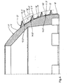
- Figure 1 shows a half section through an embodiment of a Screw according to the invention with a base body. 1 with a substantially hemispherical lateral surface 1.1, on which a two-start first thread 2 for cementless Anchoring the screw socket in the hipbone of a Patient is arranged.
- the section plane shown contains while the axis 3 of the screw.
- Inside shows the main body 1 a recess 1.2 for receiving a Inlays on, which is the later sliding surface for the femur anchored ball joint head of the hip joint prosthesis to Provides.
- the thread base 2.1 of the first thread 2 is located on the Lateral surface 1.1 of the main body 1, which in Figure 1 in the area the first thread 2 is shown in dashed lines.
- the tips 4 of the first thread 2 are substantially over the entire length of the first thread 2 on a for Lateral surface 1.1 parallel - dash-dotted in Figure 1 shown - surface 5.
- the tips 4 of the first thread 2 thus have substantially over the entire length of the first thread 2 each have the same vertical distance to the lateral surface 1.1, so that adjacent flanks 6.1 and 6.2 of the first thread 2 each have the same edge height exhibit. Only at the beginning and at the outlet of the first thread 2, both not shown in Figure 1 are, the tips 4 extend over each one relatively short section between the lateral surface 1.1 and the first surface 5.
- the thread root 2.1 essentially filling second Thread 7 arranged, whose slope is equal to the slope of the first thread 2 is. Since the first thread 2 sauten is executed, the edge 6.1 belongs to the first thread the first thread 2 and the distal adjacent Flank 6.2 to the second thread of the first thread. 2 Between the two flanks 6.1 and 6.2 of the first thread are three threads 7.1, 7.2 and 7.3 of the second Thread 7 arranged. Overall, the second thread has 7 due to the Zwetician the first thread 2 the twice the number of turns, that is six threads.
- the tips 8 of the second thread 7 are substantially over the entire length of the second thread 7 on a parallel to the lateral surface 1.1 - dash-dotted two in Figure 1 illustrated - second surface 9.
- the tips 8 of the second thread 7 thus have substantially over the entire length of the second thread 7 each the same vertical distance to the lateral surface 1.1, so that adjacent flanks 7.1 and 7.2 of the second thread. 7 each have the same edge height. Only at the beginning and at the outlet of the second thread 7, both in FIG. 1 are not shown, the tips 8 extend, Similar to the first thread 2, each one relatively short section between the lateral surface 1.1 and the second surface 9.
- flank height of flanks 7.1, 7.2 and 7.3 of the second Thread 7 is about half less than the flank height the adjacent flanks 6.1 and 6.2 of the first Thread 2. This is a significant weakening of the Hipbone into which the screw is screwed in the area between the two adjacent flanks 6.1 and 6.2 of the first thread 2 through the second thread. 7 avoided.
- the gap in the thread root 2.1 between the two flanks 6.1 and 6.2 of the first thread 2 is by between the two flanks 6.1 and 6.2 of the first Thread 2 arranged three threads 7.1, 7.2 and 7.3 the second thread 7 divided substantially uniformly, so that in addition a favorable introduction of force in the Hip bone over the first thread 2 and the second thread 7 is ensured.
- Both threads 2 and 7 are in a known manner by each Milled cuts provided over the thread length designed self-tapping, which makes a particularly good flat mating between the thread flanks and the Hip bone results, in which screwed the screw later becomes. It is understood, however, that in others Versions only one of the two threads self-tapping or possibly neither thread self-tapping is performed, with the corresponding Counter thread then with appropriate cutting tools before screwing the screw in the hip bone must be cut.
- the distal flanks 6.1 and the proximal flanks 6.2 of the first thread 2 and the distal flanks 10.1 and the proximal flanks 10.2 of the second thread run in the axial section of the screw shown in Figure 1 inclined by 80 ° to the axis 3 of the screw.
- the distal flanks 6.1 of the first thread 2 and the distal Flanks 10.1 of the second thread 7 run parallel to each other, wherein they are shown in FIG Axial section clockwise by 80 ° to axis 3 are inclined.
- the proximal flanks 6.2 of the first thread 2 and the proximal flanks 10.2 of the second thread 7 also run parallel to each other, where they in the axial section shown in Figure 1 respectively clockwise by 80 ° to the axis 3 are inclined.
- the transition region 11 in the thread root 2.1 between each two adjacent thread flanks is, as here the example the distal flank 6.1 of the first thread 2 and the proximal flank 10.2 of the first thread 7.1 of the second thread 7 shown, circular arc-shaped.
- the radius of curvature of the transition region 11 corresponds while half the flank height of the second thread 7.
- the Transition region 11 opens in each case tangentially in the distal flank 6.1 of the first thread 2 and the proximal Flank 10.2 of the first thread 7.1 of the second thread 7th
- first Thread a molded on the base body 1 circumferential Paragraph 12 during a first sub-step with a first Cutter 13 and a second cutter 14 processed.
- first cutter simultaneously generates the distal flank 6.1 of the first thread 2 and the proximal edge 10.2 of the distal flank 6.1 distally adjacent first thread turn 7.1 of the - indicated by dashed lines in Figure 2 - second thread 7.
- the second cutter generates at the same time the proximal flank 6.2 of the first thread 2 and the distal flank 10.1 of the proximal flank 6.2 proximal adjacent third thread 7.3 of the second thread 7. It is understood that instead of milling cutters but Other tools, such as lathe or but also grinding wheels or the like can be used can.
- Cutters 13 and 14 are here as disc-shaped profile cutter formed with identical tool geometry.
- the Cutting edges 13.1 and 14.1 of the first cutter 13 and des second cutter 14 thereby produce each distal flanks of the first thread 2 and the second thread 7, respectively the cutting edges 13.2 and 14.2 each proximal flanks produce the first thread 2 and the second thread 7.
- the cutting edges 13.1 and 14.1 of the first milling cutter 13 or of the second cutter 14 extend in the shown Axial section respectively according to the inclination of the distal Flanks of the first thread 2 and the second thread. 7 inclined to the screw pan axis 3.
- the cutting edges 13.2 and 14.2 again run in the axial section respectively shown according to the inclination proximal flanks of the first Thread 2 and the second thread 7th
- transition region 11 between adjacent thread flanks 6.1 and 10.2 generating section 13.3 of the milling cutter 13 is according to the contour of the transition area 11 also formed a circular arc. The same applies to section 14.3 of the second cutter 14.
- first cutter 13 and the second cutter 14 For generating mutually parallel distal thread flanks of the first and second threads and parallel to each other proximal thread flanks of the first and second threads become the first cutter 13 and the second cutter 14 in the section plane shown on a to the lateral surface 1.1 parallel trajectory parallel shifted, so that their Cutting edges 13.1 or 13.2 and 14.1 or 14.2 so always enclose the same angle with the cup axis 3.
- the screw is rotated about its axis 3, so that it is processed on its entire circumference.
- the Trajectory of the first cutter 13 and second cutter 14th runs in such a way that after a full revolution of the Screw pan around the screw pan axis 3 of the - in 2 dashed lines - positions 13 'and 14 'shifted in the position shown 13 and 14 in parallel were.
- first cutter 13 and the second cutter 14 each guided so that the circular arc Section 13.3 of the milling cutter 13 and the circular arc Section 14.3 of the second cutter 14 tangentially is guided to the lateral surface 1.1 of the base body 1, d. H. that the respective section 13.3 or 14.3, the lateral surface 1.1 of the body in each case touched in one point.
- the cutters 13 and 14 become so guided that the tips 4 of the first thread 2 on the lie to the lateral surface 1.1 parallel first surface 5.
- the axes of rotation of the first and second cutters 13 and 14 run - which in Figure 1 for reasons of clarity not shown - according to the thread pitch of the first and second threads 2 and 7 to the cutting plane inclined, wherein they are perpendicular to the cutting plane Lie flat.
- first thread 2 is double-threaded, is to simultaneous production of flanks 6.3 and 6.4 during of the first sub-step - not shown in Figure 2 with respect to the axis 3 to the first and second Cutter 13 and 14 symmetrically arranged and trained, provided second pair of milling cutters. It goes without saying, that in other variants for the production of Flanks 6.3 and 6.4 also in a second pass during the first part of the step, the cutter 13 and 14 used could become.
- a third mill 15 which has the same tool geometry like the first and second cutters 13 and 14 having.
- the angular position of the cutting edges 15.1 or 15.2 of the third cutter 15 with respect to the axis 3 corresponds the described angular position of the cutting edges 13.1 or 13.2 of the first milling cutter 13. The same applies to the orientation of the cutter axis to the cutting plane.
- the third cutter simultaneously produces the distal flank 10.3 of the first thread 7.1 of the second thread. 7 and the proximal flank 10.4 of the flank 10.3 distal adjacent second thread 7.2 of the second thread 7. It is understood that also here instead of the milling cutter another tool, such as a lathe tool or even a grinding wheel or the like can be used.
- the operation of the third cutter 15 during the second section quizes equal to that of the first cutter 13th during the first step.
- the third cutter 15 is also on a parallel to the lateral surface 1.1 Path by parallel displacement in the section plane shown method.
- the cutter 15 is guided so that the Tips 8 of the second thread 7 on the to the lateral surface 1.1 parallel first surface 9 are.
- FIG. 4 shows a partial axial section through another one Execution of the screw according to the invention. Construction and Production of this variant correspond essentially the embodiment described in Figures 1 to 3, see that here only on the differences to this version to be received.
- the first thread 2 substantially corresponds to the first Thread of Figure 1, while the second thread 7 "a significantly lower edge height than the second Thread of Figure 1.
- the flank height of the second thread 7 correlates to about one sixth of the flank height of the first thread 2 ".
- the second thread 7 is shown Example not self-tapping.
- the Flank height of the second thread 7 is so small and the thread teeth are so slim that the flanks of the second thread 7 "when screwing the screw in a recess in the hip bone possibly without problems be pressed into the hipbone.
- the contact between the thread crests 8 "and the hip bone stimulates this then to grow, so that bone tissue in the threads of the second thread 7 "grows.
- the first tool 13 "or the second tool 14” points at its respective tip section 13.3 “or 14.3” one larger cutting edge radius than the third tool 15 "at its top section 15.3".
Description
Die Erfindung betrifft eine Schraubpfanne für eine Hüftgelenksprothese
gemäß dem Oberbegriff des Anspruchs 1 sowie
ein Verfahren zu deren Herstellung.The invention relates to a screw socket for a hip joint prosthesis
according to the preamble of
Derartige Schraubpfannen werden bei der Hüftgelenksoperation in eine zuvor gefräste Aussparung im Hüftknochen des Patienten eingesetzt, die der Mantelfläche des Grundkörpers der Schraubpfanne entspricht. Anschließend wird die Schraubpfanne zur zementlosen Fixierung in den Hüftknochen eingeschraubt, bis der Grundkörper in der Aussparung am Hüftknochen anliegt und so ein weiteres Einschrauben verhindert. Das Gewinde ist dabei häufig selbstschneidend ausgeführt, so daß sich eine weitere Vorbearbeitung des Hüftknochens erübrigt. Um möglichst viel von der Knochensubstanz des Hüftknochens zu erhalten und so eine zu große Schwächung des Hüftknochens zu vermeiden, weist das Gewinde in der Regel im Axialschnitt der Schraubpfanne in relativ großem axialem Abstand zueinander angeordnete schlanke Gewindezähne auf. Der Gewindegrund zwischen den Gewindezähnen ist dabei der Mantelfläche des Grundkörpers mehr oder weniger genau nachgebildet und liegt im Idealfall in der Aussparung flächig am Hüftknochen an.Such Schraubpfannen be in the hip joint surgery into a previously milled recess in the hipbone of the Patients used the lateral surface of the main body the screw corresponds. Subsequently, the Screw socket for cementless fixation in the hip bone screwed in until the base body in the recess on Hip bone rests and so prevents further screwing. The thread is often self-tapping executed, so that a further pre-processing of Hip bone is unnecessary. To get as much of the bone substance as possible of the hip bone and so one too big To avoid weakening of the hip bone, shows the thread usually in axial section of the screw in relative large axial distance from each other arranged slim Thread teeth on. The thread root between the thread teeth is the lateral surface of the body more or less accurately modeled and is ideally in the recess flat on the hip bone.
Bei den bekannten Schraubpfannen mit konischem Grundkörper kann der Gewindegrund zwar problemlos der konischen Mantelfläche des Grundkörpers angepaßt werden, so daß der Gewindegrund im Idealfall in einer mit einem entsprechenden konischen Fräser erzeugten Aussparung vollflächig am Hüftknochen anliegt. Bei diesen Schraubpfannen besteht jedoch der Nachteil, daß beim Einschrauben der Schraubpfanne schon kleinste Winkelabweichungen zwischen der Längsachse der Ausnehmung und der Längsachse der Schraubpfanne dazu führen, daß der Grundkörper der Schraubpfanne nicht mehr vollflächig am Hüftknochen anliegt. Die Gelenklast wird dann nur noch über die Gewindeflanken und mehr oder weniger kleine Bereiche des Grundkörpers in den Hüftknochen eingeleitet, wodurch es zu einer unerwünschten lokalen Überlastung des Hüftknochens und damit zu einer Beschädigung des Knochens sowie zum Lockern der Pfanne kommen kann.In the known Schraubpfannen with conical body Although the thread base can easily the conical surface be adapted to the body, so that the thread reason ideally in one with a corresponding one conical cutters produced recess over the entire surface of the hip bone is applied. However, there is one in these Schraubpfannen the disadvantage that when screwing the screw even the smallest angular deviations between the longitudinal axis the recess and the longitudinal axis of the screw to lead that the main body of the screw no longer all over the hip bone rests. The hinge load becomes then only on the thread flanks and more or less small areas of the body in the hip bones initiated, making it an undesirable local Overloading of the hip bone and thus to damage of the bone and to loosen the pan come can.
Bei den bekannten Schraubpfannen mit halbkugelförmigem Grundkörper sind die genannten Winkelabweichungen beim Einschrauben der Schraubpfanne in den Hüftknochen unkritisch, da es aufgrund der einander entsprechenden sphärischen Konturen des Grundkörpers der Schraubpfanne und der Ausnehmung im Hüftknochen zu keinem Verkanten wie bei den konischen Schraubpfannen kommen kann. Die bekannten sphärischen Schraubpfannen weisen jedoch den Nachteil auf, daß die Anpassung des Gewindegrundes an die sphärische Kontur des Grundkörpers nur unvollständig und mit sehr aufwendigen Mitteln möglich ist.In the known Schraubpfannen with hemispherical Basic body are the mentioned angular deviations Screwing the screw socket into the hip bone uncritically, as it is due to the corresponding spherical Contours of the main body of the screw and the Recess in the hip bone to no tilting as in the conical threaded cups can come. The well-known spherical ones However, threaded cups have the disadvantage that the adaptation of the thread root to the spherical contour of the basic body only incomplete and with very elaborate Means is possible.
So offenbart beispielsweise die europäische Patentanmeldung 0 480 551 A1 eine gattungsgemäße, sphärische Schraubpfanne, bei der die sphärische Kontur des Grundkörpers im Gewindegrund durch eine Anzahl im Axialschnitt zueinander geneigt verlaufender Teilflächen polygonzugartig angenähert ist. Die Teilflächen bilden dabei an ihrem Stoß jeweils eine stumpfwinklige Dachkante. Im Gewindegrund liegt diese Schraubpfanne somit ebenfalls nicht vollflächig sondern nur im Bereich der Dachkanten am Hüftknochen an. Um in der sphärischen Ausnehmung ein möglichst großflächiges Anliegen der Schraubpfanne am Hüftknochen zu erzielen, ist es bei dieser Schraubpfanne erforderlich, die sphärische Kontur des Grundkörpers durch viele zueinander geneigte Teilflächen möglichst genau anzunähern, womit allerdings ein erheblich erhöhter Fertigungsaufwand erforderlich ist.For example, the European patent application discloses 0 480 551 A1 a generic spherical screw pan, in which the spherical contour of the main body in Thread base by a number in axial section to each other inclined extending partial surfaces approximated polygonzugartig is. The faces form at their respective impact an obtuse-angled roof edge. In the thread base is This screw thus also not full surface but only in the area of the roof edges on the hip bone. Around in the spherical recess as large as possible Concerning the screw socket on the hip bone is to achieve it required in this screw pan, the spherical Contour of the main body by many inclined to each other To approximate partial areas as closely as possible, which however a significantly increased production cost is required.
Ein weiterer Nachteil der bekannten gattungsgemäßen Schraubpfannen besteht darin, daß schon relativ geringe Abweichungen des Grundkörpers der Schraubpfanne oder der Aussparung im Hüftknochen von der Idealgeometrie dazu führen können, daß unter Umständen große Bereiche des Grundkörpers in der Aussparung nicht am Hüftknochen anliegen und somit nicht an der Lasteinleitung in den Hüftknochen teilnehmen. Gerade beim Ausfräsen der Aussparung im Hüftknochen, das der Chirurg in der Regel von Hand vornimmt, kann es selbst bei erhöhter Sorgfalt, z. B. durch nicht exakt axiale Kraftausübung auf den Knochenfräser oder durch unbeabsichtigtes Schwenken der Fräserachse während des Fräsens, schnell zu derartigen Abweichungen der Aussparung von der Idealgeometrie kommen.Another disadvantage of the known generic Schraubpfannen is that even relatively small Deviations of the main body of the screw or the Lead recess in the hip bone of the ideal geometry can, that under circumstances large areas of the main body do not rest on the hipbone in the recess and thus not at the load transfer into the hip bone take part. Especially when milling out the recess in the hip bone, that the surgeon usually does by hand, It can even with increased care, z. B. not by exact axial force on the bone cutter or by unintentionally pivoting the cutter axis during milling, quickly to such deviations of the recess come from the ideal geometry.
Dokument FR-A-2 610 512 offenbart eine Schraubpfanne gemäß des Oberbegrifß von Anspruch 1.Document FR-A-2 610 512 discloses a threaded cup according to the preamble of
Der Erfindung liegt deshalb die Aufgabe zugrunde, eine gattungsgemäße Schraubpfanne zur Verfügung zu stellen, die die genannten Nachteile nicht oder zumindest in geringerem Maße aufweist, wobei sie insbesondere bei einfacher Herstellbarkeit der Schraubpfanne eine gleichmäßige Einleitung der Gelenklasten in den Hüftknochen und eine zuverlässige Fixierung sicherstellt. Weiterhin liegt der Erfindung die Aufgabe zugrunde, ein Herstellungsverfahren für eine derartige Schraubpfanne anzugeben.The invention is therefore based on the object, a To provide generic screw available, the the disadvantages mentioned or not at least in less Has dimensions, in particular with ease of manufacture the screw pan a uniform introduction the joint loads in the hip bone and a reliable Fixation ensures. Furthermore, the invention is the task is based on a manufacturing process for to specify such a screw.
Die Aufgabe wird, ausgehend von einer Schraubpfanne gemäß
dem Oberbegriff des Anspruchs 1, durch die im kennzeichnenden
Teil des Anspruchs 1 angegebenen Merkmale gelöst. The task is, starting from a screw according to
the preamble of
Die Erfindung schließt die technische Lehre ein, daß man eine schnell und einfach herzustellende Schraubpfanne mit guter Krafteinleitung in den Hüftknochen erhält, wenn auf der Außenseite des Grundkörpers der Schraubpfanne zwischen zwei benachbarten Flanken des ersten Gewindes wenigstens ein den Gewindegrund des ersten Gewindes ausfüllendes zweites Gewinde vorgesehen ist, dessen lokale Flankenhöhe senkrecht zur Mantelfläche des Grundkörpers über im wesentlichen die gesamte Länge des zweiten Gewindes wesentlich geringer ist als die lokale Flankenhöhe der beiden benachbarten Flanken des ersten Gewindes. Unter lokaler Flankenhöhe soll hierbei der in dem jeweiligen Punkt des Gewindes senkrecht zur Mantelfläche des Grundkörpers gemessene Abstand der Gewindespitze zur Mantelfläche des Grundkörpers verstanden werden. Weisen die beiden benachbarten Flanken des ersten Gewindes unterschiedliche Flankenhöhe auf, so ist die lokale Flankenhöhe des zweiten Gewindes geringer als die lokale Flankenhöhe der kürzeren der beiden benachbarten Flanken. Der Betrag, um den die lokale Flankenhöhe des zweiten Gewindes geringer ist als die lokale Flankenhöhe der beiden benachbarten Flanken des ersten Gewindes, ist dabei ausreichend groß gewählt, so daß eine wesentliche Schwächung des Hüftknochens durch das zweite Gewinde vermieden ist. Die Steigung des zweiten Gewindes entspricht dabei aus Gründen der einfacheren Fertigung vorzugsweise der Steigung des ersten Gewindes.The invention includes the technical teaching that one a quick and easy to manufacture screw with good force introduction in the hip bone gets when on the outside of the main body of the screw between two adjacent flanks of the first thread at least a filling the thread root of the first thread second thread is provided, the local flank height perpendicular to the lateral surface of the body about substantially the entire length of the second thread essential is less than the local flank height of the two adjacent flanks of the first thread. Under local Flankenhöhe should here in the respective point of Thread measured perpendicular to the lateral surface of the body Distance of the thread crest to the lateral surface of the Basic body be understood. Assign the two adjacent ones Flanks of the first thread different flank height on, this is the local flank height of the second thread less than the local flank height of the shorter ones the two adjacent flanks. The amount by which the local flank height of the second thread is less than the local flank height of the two adjacent flanks of the first thread, it is sufficiently large, so that a substantial weakening of the hip bone by the second thread is avoided. The slope of the second thread corresponds to reasons of easier production preferably the pitch of the first thread.
Das im Gewindegrund des ersten Gewindes angeordnete zweite Gewinde stellt gegenüber den bekannten Schraubpfannen eine vergrößerte Kontaktfläche und besseren Kontakt zwischen der Schraubpfanne und dem Hüftknochen sicher. Je nach Flankenhöhe des zweiten Gewindes ergibt sich der verbesserte Kontakt zwischen Schraubpfanne und Hüftknochen aus zwei sich gegebenenfalls überlagernden Effekten des zweiten Gewindes.The second thread arranged in the thread root of the first thread Thread is compared to the known threaded cups one increased contact area and better contact between the screw and the hip bone safely. Depending on Flank height of the second thread results in the improved Contact between screw cup and hip bone two possibly overlapping effects of the second Thread.
Weist das zweite Gewinde zum einen eine so geringe Flankenhöhe auf, daß es nicht in den Hüftknochen eingeschraubt wird, sondern die Spitzen des zweiten Gewindes nur mehr oder weniger stark gegen den Hüftknochen gedrückt werden, so regt diese mit Belastung des Gelenkes über die Spitzen des zweiten Gewindes übertragene, schwellende Drucklast das Knochengewebe zu verstärktem Wachstum an. Hierbei ist es für das Wachstum förderlich, daß die Drucklast nicht großflächig sondern nur über die relativ schmalen Gewindespitzen des zweiten Gewindes in den Hüftknochen eingeleitet wird. Das somit in die Gewindegänge des zweiten Gewindes einwachsende Knochengewebe verbessert dabei den Kontakt zwischen Schraubpfanne und Hüftknochen erheblich gegenüber den bekannten Schraubpfannen mit mehr oder weniger glattem Gewindegrund zwischen den Flanken des ersten Gewindes. Dies gilt auch dann, wenn die Schraubpfanne nicht exakt in Axialrichtung der Aussparung im Hüftknochen eingeschraubt wird oder die Aussparung im Hüftknochen in der oben beschriebenen Weise von der Idealgeometrie abweicht und der Gewindegrund des ersten Gewindes somit, wie eingangs geschildert, nicht vollständig in der Aussparung am Hüftknochen anliegt. Aufgrund der naturgemäß relativ spitzwinkligen Ausführung werden die Gewindespitzen des zweiten Gewindes beim Einschrauben der Schraubpfanne ohne weiteres in den Hüftknochen gedrückt bis der Gewindegrund in ihrem Bereich am Hüftknochen anliegt und ein weiteres Einschrauben behindert. In Bereichen, in denen Zwischenräume zwischen Hüftknochen und Gewindegrund auftreten, überbrückt das zweite Gewinde derartige Zwischenräume. Der oben geschilderte Effekt tritt auch hier ein, da schon relativ leichter Kontakt der Gewindespitzen mit dem Hüftknochen ausreicht, um das Knochenwachstum anzuregen und somit den Zwischenraum zwischen Hüftknochen und Gewindegrund auszufüllen. Mehr oder weniger unvermeidbare Fehler beim Einsetzen der Schraubpfanne bzw. beim Ausfräsen der Aussparung im Hüftknochen aber auch Abweichungen des Grundkörpers der Schraubpfanne von der Idealgeometrie werden hierdurch in einfacher Weise zuverlässig kompensiert.Does the second thread on the one hand such a low edge height on that it is not screwed into the hipbone is, but the tips of the second thread only more or less strongly pressed against the hip bone, so this stimulates with load of the joint over the tips the second thread transmitted, swelling pressure load the bone tissue to increased growth. Here is it conducive to growth, that the pressure load is not large area but only on the relatively narrow thread crests of the second thread introduced into the hip bone becomes. The thus in the threads of the second thread ingrowing bone tissue improves contact between screw and hip bone considerably opposite the known screw with more or less smooth thread root between the flanks of the first thread. This is true even if the screw is not screwed exactly in the axial direction of the recess in the hip bone or the recess in the hip bone in the deviates from the ideal geometry described above and the thread root of the first thread thus, as at the outset portrayed, not completely in the recess at Hip bone is present. Due to the nature of relative acute-angled execution are the thread crests of the second thread when screwing the screw without Another pressed into the hip bone until the thread bottom in her area rests on the hip bone and another Screwing obstructed. In areas where spaces occur between hip bone and thread root, the second thread bridges such gaps. Of the above described effect also occurs here, since already relatively easy contact of the thread crests with the hipbone sufficient to stimulate bone growth and thus the space between the hip bone and the base of the thread fill. More or less unavoidable mistakes Insert the screw socket or when milling out the recess in the hip bone but also deviations of the body the screw pan of the ideal geometry thereby compensated reliably in a simple manner.
Weist das im Gewindegrund des ersten Gewindes angeordnete zweite Gewinde zum anderen eine so große Flankenhöhe auf, daß es ebenfalls in den Hüftknochen eingeschraubt wird, so stellt es durch seine in den Knochen eingreifenden Flanken gegenüber den bekannten Schraubpfannen eine vergrößerte Kontaktfläche zwischen der Schraubpfanne und dem Hüftknochen sicher. Dies gilt insbesondere gerade dann, wenn die Schraubpfanne nicht exakt in Axialrichtung der Aussparung im Hüftknochen eingeschraubt wird oder die Aussparung im Hüftknochen in der oben beschriebenen Weise von der Idealgeometrie abweicht und der Gewindegrund des ersten Gewindes somit, wie eingangs geschildert, nicht vollständig in der Aussparung am Hüftknochen anliegt. Das zweite Gewinde überbrückt derartige eventuelle Zwischenräume im Gewindegrund des ersten Gewindes zwischen der Schraubpfanne und dem Hüftknochen. Der in den Hüftknochen eingreifende Anteil der Gewindeflanken des zweiten Gewindes stellt dann immer noch eine ausreichend große Fläche zur schonenden Einleitung der Gelenklasten in den Hüftknochen sicher. Mehr oder weniger unvermeidbare Fehler beim Einsetzen der Schraubpfanne bzw. beim Ausfräsen der Aussparung im Hüftknochen aber auch Abweichungen des Grundkörpers der Schraubpfanne von der Idealgeometrie werden hierdurch in einfacher Weise zuverlässig kompensiert.Indicates that arranged in the thread root of the first thread second thread on the other such a large flank height, that it is also screwed into the hip bone, so put it through his bones engaging in the bones compared to the known screw an enlarged Contact surface between the screw socket and the hip bone for sure. This is especially true when the Screw socket not exactly in the axial direction of the recess screwed in the hip bone or the recess in the Hip bone in the manner described above of the ideal geometry deviates and the thread root of the first thread thus, as described above, not completely in the recess rests against the hip bone. The second thread bridges such possible gaps in the thread root the first thread between the screw and the hip bone. The part engaging in the hip bone the thread flanks of the second thread then sets still a sufficiently large area for gentle Initiation of joint loads in the hip bones safely. More or less unavoidable errors when inserting the Screw socket or when milling the recess in the hip bone but also deviations of the main body of the Screw socket of the ideal geometry are thereby in easily compensated reliably.
Es versteht sich, daß sich bei entsprechender Flankenhöhe des zweiten Gewindes und mehr oder weniger starker Ausprägung der genannten Abweichungen beide genannten Effekte auch einander überlagert auftreten können.It is understood that with appropriate edge height of the second thread and more or less pronounced expression the aforementioned deviations both effects mentioned can also occur superimposed on each other.
Da die Herstellung des zweiten Gewindes insbesondere bei Schraubpfannen mit sphärischem Grundkörper bedeutend einfacher zu bewerkstelligen ist als die oben beschriebene aufwendige Anpassung des Gewindegrundes des ersten Gewindes an den Grundkörper, reduziert sich auch der Herstellungsaufwand für die erfindungsgemäßen Schraubpfannen gegenüber den bekannten Schraubpfannen zum Teil erheblich.Since the production of the second thread in particular at Screw pans with spherical base much easier to accomplish is that described above complex adaptation of the thread root of the first thread to the body, also reduces the production cost for the screw according to the invention compared the known Schraubpfannen partly considerable.
Die Flankenhöhe des zweiten Gewindes ist dabei so gering gewählt, daß sichergestellt ist, daß der Hüftknochen nicht wesentlich durch das zweite Gewinde geschwächt wird, wie dies beispielsweise der Fall wäre, wenn die Flankenhöhe des zweiten Gewindes etwa im Bereich der Flankenhöhe des ersten Gewindes läge. In diesem Fall würde zum einen unvorteilhafterweise eine große Menge lebenden Hüftknochengewebes entfernt, zum anderen wäre die Festigkeit des Hüftknochens durch den aufgrund des relativ geringen Abstandes zwischen benachbarten Gewindespitzen verringerten Spannungsquerschnitt und die erhöhte Kerbwirkung im Grund des in den Hüftknochen geschnittenen Gegengewindes erheblich reduziert. Die erfindungsgemäß ausreichend geringe Flankenhöhe des zweiten Gewindes bewirkt, daß möglichst viel lebendes Knochengewebe erhalten bleibt und somit die mechanischen Eigenschaften des Knochens im Einschraubbereich so weit wie möglich erhalten bleiben.The flank height of the second thread is so low chosen that ensures that the hip bone is not is significantly weakened by the second thread, like this would be the case, for example, if the flank height of the second thread approximately in the region of the flank height of first thread would be. In this case, on the one hand, unfavorably a large amount of living hip bone tissue removed, on the other hand would be the strength of the Hip bone due to the relatively short distance reduced between adjacent thread crests Stress cross section and the increased notch effect in the ground of the cut in the hip bone counter thread considerably reduced. The invention sufficiently low Flank height of the second thread causes as possible much living bone tissue is preserved and thus the mechanical properties of the bone in Einschraubbereich to be preserved as much as possible.
Die fakultativen Merkmale günstiger Weiterbildungen der Erfindung sind in den Unteransprüchen angegeben, welche den Gegenstand der erfindungsgemäßen Lösung nicht einschränken.The facultative features of favorable developments of the Invention are given in the dependent claims, which do not limit the subject of the solution according to the invention.
So ist die lokale Flankenhöhe des zweiten Gewindes ist vorzugsweise so gewählt, daß sie um wenigstens ein Drittel, vorzugsweise wenigstens die Hälfte, geringer ist als die lokale Flankenhöhe der gegebenenfalls kürzeren der beiden benachbarten Flanken des ersten Gewindes. Durch diese Abmessungen ist eine wesentliche Schwächung des Hüftknochens durch das zweite Gewinde zuverlässig ausgeschlossen. Um eventuelle Lücken zwischen der Schraubpfanne und dem Hüftknochen zuverlässig überbrücken zu können ist die lokale Flankenhöhe des zweiten Gewindes vorzugsweise im wesentlichen um höchstens 95% geringer gewählt als die lokale Flankenhöhe der gegebenenfalls kürzeren der beiden benachbarten Flanken des ersten Gewindes. Dabei versteht es sich, daß das zweite Gewinde zum einen auch über seine Länge eine variierende Flankenhöhe aufweisen kann. Zum anderen können auch benachbarte Gänge des zweiten Gewindes unterschiedliche Flankenhöhe aufweisen, insbesondere können die durch die Flanken des ersten Gewindes getrennten Gänge des zweiten Gewindes unterschiedliche Flankenhöhe aufweisen.So that's the local flank height of the second thread preferably chosen to be at least one third preferably at least half, is less than the local flank height of possibly shorter of two adjacent flanks of the first thread. By these dimensions is a significant weakening of the Hip bone reliably excluded by the second thread. To eliminate any gaps between the screw pan and the hip bone can be reliably bridged the local edge height of the second thread preferably essentially less than 95% lower than the local flank height of possibly shorter of the two adjacent flanks of the first thread. It understands It is that the second thread on the one hand over his Length may have a varying edge height. On the other hand can also have adjacent passages of the second thread have different flank height, in particular can separated by the flanks of the first thread Gears of the second thread different flank height exhibit.
Bei den erfindungsgemäßen Schraubpfannen kann es sich um prinzipiell in herkömmlicher Weise aufgebaute Schraubpfannen aus einem biokompatiblen Material, insbesondere biokompatiblem Metall oder einer entsprechenden Metallegierung, handeln, die im Pfanneninneren eine Aussparung zur Aufnahme eines Inlays, beispielsweise aus Kunststoff etc., aufweisen, das dann die Gleitfläche für den im Femur verankerten Kugelkopf des künstlichen Hüftgelenkes bildet.In the screw according to the invention may be in principle constructed in conventional manner threaded cups from a biocompatible material, in particular biocompatible Metal or a corresponding metal alloy, acting in the pan interior a recess for Receiving an inlay, for example made of plastic, etc., which then the sliding surface for the anchored in the femur Ball head of the artificial hip joint forms.
Bei vorteilhaften Ausführungen der erfindungsgemäßen Schraubpfanne ist das erste, alternativ oder vorzugsweise zusätzlich auch das zweite Gewinde selbstschneidend ausgebildet. Gegenüber Gewinden, deren Gegengewinde zuvor mit entsprechenden Werkzeugen in den Hüftknochen eingeschnitten werden muß, ergibt sich dabei der Vorteil, daß über das gesamte Gewinde eine gute flächige Paarung zwischen dem jeweiligen selbstschneidenden Gewinde und dem Hüftknochen vorliegt, die nicht durch Formabweichungen zwischen dem Schneidwerkzeug und der Schraubpfanne oder durch Fehler beim Gewindeschneiden beeinflußt wird. Es versteht sich jedoch, daß sich bei entsprechend geringer Flankenhöhe eine selbstschneidende Ausführung des zweiten Gewindes erübrigt.In advantageous embodiments of the invention Screw is the first, alternatively or preferably in addition, the second thread formed self-tapping. Opposite threads whose mating thread previously with corresponding tools cut in the hipbone must be, this results in the advantage that over the whole thread has a good plane pairing between the respective self-tapping thread and the hip bone that is not due to form deviations between the cutting tool and the screw or by mistake when tapping is affected. It understands However, that at correspondingly low edge height a self-tapping version of the second thread unnecessary.
Bei günstigen Varianten der erfindungsgemäßen Schraubpfanne ist das erste Gewinde, alternativ oder zusätzlich auch das zweite Gewinde mehrgängig ausgebildet, wobei vorzugsweise die Gangzahl des zweiten Gewindes einem ganzzahligen Vielfachen der Gangzahl des ersten Gewindes entspricht. Hierbei soll die angegebene Gangzahl des zweiten Gewindes als auf ein einziges zweites Gewinde bezogen verstanden werden, das im Grund des ersten Gewindes angeordnet ist und dessen Gänge auf die einzelnen Gänge des ersten Gewindes verteilt angeordnet sind. Weiter vorzugsweise ist das erste Gewinde in bekannter Weise zweigängig und das zweite Gewinde wenigstens viergängig ausgebildet ist. Im Sinne der oben genannten Terminologie sind also zwischen zwei Flanken des ersten Gewindes jeweils wenigstens zwei Flanken des zweiten Gewindes angeordnet. Hierdurch wird eine gute und gleichmäßige Ausfüllung des Gewindegrundes des ersten Gewindes mit einem zweiten Gewinde ausreichend geringer Flankenhöhe erzielt.In favorable variants of the screw according to the invention is the first thread, alternatively or additionally the second thread formed more continuous, preferably the number of threads of the second thread an integer Multiples the number of turns of the first thread corresponds. Here, the specified number of threads of the second thread as understood relative to a single second thread which is located at the bottom of the first thread and its gears to the individual passages of the first thread are arranged distributed. More preferably, that is first thread in a known manner zweigängig and the second Thread is formed at least four. For the purpose of So the terminology above is between two Flanks of the first thread in each case at least two flanks arranged the second thread. This will be a good and uniform filling of the thread of the first thread with a second thread sufficiently lower Flank height achieved.
Vorteilhafte Weiterbildungen der Schraubpfanne zeichnen sich dadurch aus, daß das zweite Gewinde derart ausgebildet und angeordnet ist, daß der Zwischenraum im Gewindegrund zwischen zwei Flanken des ersten Gewindes im Axialschnitt der Schraubpfanne durch den zwischen den zwei Flanken des ersten Gewindes angeordneten Gewindegang des zweiten Gewindes oder die zwischen den zwei Flanken des ersten Gewindes angeordneten Gewindegänge des zweiten Gewindes im wesentlichen gleichmäßig unterteilt ist. Hierdurch wird zum einen eine besonders gleichmäßige Einleitung der Gelenklasten in den Hüftknochen erreicht. Zum anderen lassen sich derart gleichmäßige Teilungen besonders einfach mit nur wenigen Werkzeugen herstellen.Draw advantageous developments of the screw characterized in that the second thread is formed and arranged that the gap in the thread root between two flanks of the first thread in axial section the screw through the between the two Flanks of the first thread arranged thread of the second thread or between the two flanks of the first thread arranged threads of the second thread is divided substantially equally. hereby on the one hand, a particularly even introduction achieved the joint loads in the hip bone. On the other hand let such uniform divisions especially easy to make with just a few tools.
Bei besonders günstigen Varianten ist der Übergangsbereich zwischen zwei Flanken im Gewindegrund im Axialschnitt der Schraubpfanne im wesentlichen bogenförmig ausgebildet, beispielsweise ellipsen- oder kreisbogenförmig, wodurch die Kerbwirkung im Fußbereich der Gewindezähne verringert ist. Bei herstellungstechnisch besonders bevorzugten Varianten ist der Übergangsbereich im wesentlichen kreisbogenförmig ausgebildet, wobei er jeweils im wesentlichen tangential in eine der beiden Flanken mündet und einen Krümmungsradius aufweist, der höchstens im wesentlichen der halben Flankenhöhe des zweiten Gewindes entspricht. Dank dieses einfachen kreisbogenförmigen Übergangsbereiches gestaltet sich zum einen auch der diesen Bereich des ersten bzw. zweiten Gewindes erzeugende Abschnitt des bzw. der Bearbeitungswerkzeuge ebenfalls besonders einfach. So weist beispielsweise der diesen Bereich des ersten bzw. zweiten Gewindes erzeugende Werkzeugabschnitt bei einem Drehmeißel eine einfache ebenfalls kreisbogenförmige Schneidkante auf. Zum anderen ist eine Anpassung des Gewindegrundes an die Kontur des Grundkörpers besonders einfach zu bewerkstelligen, da der den Gewindegrund bearbeitende kreisbogenförmige Werkzeugabschnitt problemlos über den gesamten Gewindeverlauf tangential zur Kontur des Grundkörpers geführt werden kann, so daß der Gewindegrund der Kontur des Grundkörpers folgt. Der begrenzte Ausrundungsradius dient dabei zur Sicherstellung einer ausreichenden Länge des jeweiligen geraden Flankenabschnittes, der den Flankenwinkel des zweiten Gewindes und damit die Trag- und gegebenenfalls auch die Schneideigenschaften des zweiten Gewindes bestimmt.In particularly favorable variants, the transition region between two flanks in the thread root in the axial section of Schraubpfanne formed substantially arcuate, for example, elliptical or circular arc, whereby reduces the notch effect in the foot area of the thread teeth is. In manufacturing technology particularly preferred variants the transition region is essentially circular arc-shaped each being substantially tangential opens into one of the two flanks and a radius of curvature having at most substantially the half flank height of the second thread corresponds. thanks designed this simple circular arc transition area on the one hand also this area of the first or second thread-generating portion of or Machining tools also very easy. So For example, if this area of the first or second thread-generating tool section at a Turning tool a simple also arcuate Cutting edge on. On the other hand is an adaptation of the thread to the contour of the body particularly simple to accomplish because of the thread root processing circle-shaped tool section easily over the entire thread tangential to the contour of the Main body can be performed so that the thread reason follows the contour of the body. The limited radius of curvature serves to ensure a sufficient Length of the respective straight flank section, the flank angle of the second thread and thus the Load and possibly also the cutting properties of the second thread determined.
Bei bevorzugten Ausführungen der erfindungsgemäßen Schraubpfanne verlaufen die distalen Flanken des ersten Gewindes und die distalen Flanken des zweiten Gewindes im Axialschnitt der Schraubpfanne zur Achse der Schraubpfanne um einen Winkel von im wesentlichen 70° bis 90°, vorzugsweise 75° bis 85°, geneigt. Die proximalen Flanken des ersten Gewindes und die proximalen Flanken des zweiten Gewindes verlaufen im Axialschnitt der Schraubpfanne ebenfalls um einen Winkel von im wesentlichen 70° bis 90°, vorzugsweise 75° bis 85°, zur Achse der Schraubpfanne geneigt. Hierdurch ergibt sich sowohl hinsichtlich der Festigkeit der Gewinde als auch hinsichtlich der Werkstoffpaarung aus Schraubpfanne und Knochen ein besonders günstiger Schlankheitsgrad der Gewindeflanken. In preferred embodiments of the invention Schraubpfanne run the distal flanks of the first Thread and the distal flanks of the second thread in the Axial section of the screw socket to the axis of the screw socket at an angle of substantially 70 ° to 90 °, preferably 75 ° to 85 °, inclined. The proximal flanks of the first Thread and the proximal flanks of the second thread extend in axial section of the screw also at an angle of substantially 70 ° to 90 °, preferably 75 ° to 85 °, inclined to the axis of the screw. This results both in terms of strength the thread as well as the material pairing made of screw and bone a particularly favorable Slenderness of thread flanks.
Vorzugsweise verlaufen dabei die distalen und proximalen Flanken des ersten Gewindes sowie die distalen und proximalen Flanken des zweiten Gewindes im Axialschnitt der Schraubpfanne zur Achse der Schraubpfanne um betragsmäßig im wesentlichen denselben Winkel geneigt. Aufgrund dieser Symmetrie ergibt sich eine besonders einfache Gestaltung und Führung des bzw. der die Gewinde erzeugenden Werkzeuge, mithin also eine besonders kostengünstige Herstellung der Schraubpfannen. Dieser Vorteil hinsichtlich der Gestaltung und Führung des bzw. der die Gewinde erzeugenden Werkzeuge erhöht sich noch weiter, wenn vorzugsweise die distalen Flanken des ersten Gewindes und die distalen Flanken des zweiten Gewindes sowie die proximalen Flanken des ersten Gewindes und die proximalen Flanken des zweiten Gewindes zueinander im wesentlichen parallel verlaufen. Zur Herstellung des ersten und zweiten Gewindes ist es dann möglich, ein und dieselbe Werkzeuggeometrie, insbesondere dasselbe bzw. dieselben Werkzeuge zu verwenden.Preferably, the distal and proximal extend Flanks of the first thread as well as the distal and proximal ones Flanks of the second thread in the axial section of the Screw socket to the axis of the screw to amount tilted at substantially the same angle. Based on these Symmetry results in a particularly simple design and guiding the thread forming tool (s), So therefore a particularly cost-effective production the screw-pans. This advantage in terms of design and guide the thread-generating or the Tools increases even further, if preferably the distal flanks of the first thread and the distal ones Flanks of the second thread and the proximal flanks of the first thread and the proximal flanks of the second Thread to each other substantially parallel. It is for making the first and second threads then possible, one and the same tool geometry, in particular to use the same or the same tools.
Besonders einfach hinsichtlich der Fertigung aber auch besonders günstig hinsichtlich der Einleitung der Gelenklasten in den Hüftknochen gestalten sich Ausführungen der Schraubpfanne, bei denen die Spitzen des ersten Gewindes über im wesentlichen die gesamte Länge des ersten Gewindes auf einer zur Mantelfläche des Grundkörpers im wesentlichen parallelen ersten Fläche liegen und die Spitzen des zweiten Gewindes über im wesentlichen die gesamte Länge des zweiten Gewindes auf einer zur Mantelfläche des Grundkörpers im wesentlichen parallelen zweiten Fläche liegen. Die Flanken des ersten bzw. des zweiten Gewindes weisen dabei dann über die Länge des ersten bzw. des zweiten Gewindes jeweils dieselbe Flankenhöhe auf. Hierbei sind insbesondere die genannten vorteilhaften Varianten mit konstanten Neigungswinkeln der Flanken des ersten und zweiten Gewindes zur Achse der Schraubpfanne besonders einfach zu fertigen, da das bzw. die Werkzeuge zur Erzeugung des ersten bzw. zweiten Gewindes durch Parallelverschiebung auf einfachen, parallel zur Mantelfläche des Grundkörpers verlaufenden Bahnkurven geführt werden müssen.Especially simple in terms of production but also very special favorable with regard to the initiation of the joint loads in the hip bones, designs of the Screw-in pan, where the tips of the first thread over substantially the entire length of the first thread on a to the lateral surface of the body substantially lie parallel first surface and the tips of the second thread over substantially the entire length of the second thread on a to the lateral surface of the body lie substantially parallel second surface. The flanks of the first and the second thread have then over the length of the first and second threads each have the same flank height. Here are in particular the mentioned advantageous variants with constant Inclination angles of the flanks of the first and second Thread to the axis of the screw particularly easy to finished, since the or the tools for generating the first or second thread by parallel displacement simple, parallel to the lateral surface of the body running Trajectories must be performed.
Die im wesentlichen zur Pfannenachse rotationssymmetrische Mantelfläche des Grundkörpers kann im wesentlichen die Form eines Kegelstumpfes, eines Ellipsoidteiles oder eines Paraboloidteiles aufweisen. Besonders vorteilhafte Varianten der Schraubpfanne zeichnen sich durch eine im wesentlichen halbkugelförmige Mantelfläche des Grundkörpers aus. Diese kugeligen Schraubpfannen nähern die Gelenkgeometrie des gesunden Hüftgelenks besser an als konische Varianten. Sie erfordern daher zum einen vorteilhafterweise die Resektion einer geringeren Menge lebenden Knochengewebes und weisen eine dem gesunden Gelenk ähnlichere Lasteinleitung in den Hüftknochen auf.The rotationally symmetrical to the pan axis substantially Mantle surface of the body can essentially the Shape of a truncated cone, an ellipsoidal part or a Paraboloidteiles have. Particularly advantageous variants the screw are characterized by a substantially hemispherical shell surface of the main body. These spherical cups approach the geometry of the joint of the healthy hip joint better than conical variants. They therefore advantageously require resection on the one hand a lesser amount of living bone tissue and have a similar to the healthy joint load application in the hip bones.
Die Erfindung betrifft weiterhin ein Verfahren zur spanenden Herstellung einer erfindungsgemäßen Schraubpfanne, bei dem die Schraubpfanne in einem ersten Teilschritt zur Erzeugung des ersten Gewindes mit wenigstens einem ersten Werkzeug und einem zweiten Werkzeug bearbeitet wird. Die restlichen Flanken des zweiten Gewindes können dabei im wesentlichen zeitgleich während des ersten Teilschrittes hergestellt werden. Alternativ kann ihre Herstellung auch in einem zweiten Teilschritt erfolgen. Das erste Werkzeug ist dabei vorzugsweise derart ausgebildet, daß es gleichzeitig die distale Flanke des ersten Gewindes und die proximale Flanke des distal benachbarten Abschnitts des zweiten Gewindes erzeugt, während das zweite Werkzeug derart ausgebildet ist, daß es gleichzeitig die proximale Flanke des ersten Gewindes und die distale Flanke des proximal benachbarten Abschnitts des zweiten Gewindes erzeugt. Die Herstellung der Schraubpfanne gestaltet sich dabei besonders schnell und damit kostengünstig, weil die den Flanken des ersten Gewindes benachbarten und zugewandten Flanken des zweiten Gewindes nach Herstellung des ersten Gewindes nicht weiter bearbeitet werden müssen und insbesondere auch kein zusätzliches Werkzeug hierfür erforderlich ist.The invention further relates to a method for machining Production of a screw according to the invention, in the screw in a first sub-step for generating of the first thread with at least a first one Tool and a second tool is edited. The remaining flanks of the second thread can in the substantially simultaneously during the first substep getting produced. Alternatively, their manufacture can also take place in a second sub-step. The first tool is preferably designed such that it simultaneously the distal flank of the first thread and the proximal edge of the distally adjacent portion of the second thread while the second tool so is formed so that it is at the same time the proximal Flank of the first thread and the distal flank of the generated proximal adjacent portion of the second thread. The production of the screw is designed doing so very fast and therefore cost, because the the flanks of the first thread adjacent and facing Flanks of the second thread after production of the first Thread need not be further processed and In particular, no additional tool required for this is.
Es versteht sich jedoch, daß bei anderen Varianten der Erfindung die jeweiligen Flanken des ersten bzw. zweiten Gewindes jeweils in einzelnen Arbeitsgängen durch das jeweilige Werkzeug bzw. durch unterschiedliche Werkzeuge hergestellt werden können.It is understood, however, that in other variants of the invention the respective flanks of the first and second threads each in individual operations by the respective Tool or produced by different tools can be.
Weist das erste Gewinde mehr als einen Gewindegang auf, so wird es durch entsprechend aufeinanderfolgendes Bearbeiten des Pfannenkörpers mit dem ersten und zweiten Werkzeug oder durch gleichzeitiges Bearbeiten mit einer der Gangzahl entsprechenden Anzahl über den Pfannenumfang verteilter erster und zweiter Werkzeuge hergestellt. Ist das zweite Gewinde dabei eingängig ausgebildet, so entfällt eine weitere Bearbeitung des zweiten Gewindes vollständig, da dessen proximale und distale Flanken erfindungsgemäß bereits unmittelbar bei der Herstellung des ersten Gewindes mit dem bzw. den ersten und zweiten Werkzeugen erfolgt.If the first thread has more than one turn, so it is done by appropriately sequential editing the pan body with the first and second tools or by simultaneously working with one of the number of gears corresponding number distributed over the pan circumference first and second tools made. Is this second thread thereby formed catchy, so omitted further processing of the second thread completely, since its proximal and distal flanks according to the invention already directly in the production of the first thread with the first and second tools.
Bei einer bevorzugten Variante des Verfahrens wird die Schraubpfanne zur Herstellung der restlichen Flanken des zweiten Gewindes während des ersten Teilschrittes mit wenigstens einem dritten Werkzeug bearbeitet. Das dritte Werkzeug ist dabei derart ausgebildet ist, daß es gleichzeitig die proximale Flanke eines ersten Abschnitts des zweiten Gewindes und die distale Flanke des dem ersten Abschnitt proximal benachbarten zweiten Abschnitts des zweiten Gewindes erzeugt. Die einander zugewandten Flanken benachbarter Abschnitte des zweiten Gewindes werden also in einem Arbeitsgang mit einem dritten Werkzeug gefertigt. Weist das zweite Gewinde mehr als zwei Gewindegänge auf, so wird es gleichzeitig mit der Bearbeitung durch das erste und zweite Werkzeug mit einer Anzahl von dritten Werkzeugen bearbeitet, die der um Eins verringerten Gangzahl des zweiten Gewindes entspricht. Weist das zweite Gewinde also drei Gewindegänge auf, so sind bei dieser Variante dem ersten und zweiten Werkzeug zwei dritte Werkzeuge zugeordnet. Ist das erste Gewinde dabei dann noch mehrgängig, so ist für den geschilderten Fall im wesentlichen zeitgleicher Erstellung der Gewindegänge des ersten Gewindes jedem Paar aus erstem und zweitem Werkzeug eine entsprechende Anzahl an dritten Werkzeugen zugeordnet. Bei einem zweigängigen ersten Gewinde und einem sechsgängigen zweiten Gewinde wären für den Fall einer im wesentlichen Zeitgleichen Herstellung sämtlicher Gewindegänge zwei Paare aus jeweils einem ersten, einem zweiten und zwei dritten Werkzeugen erforderlich, die dann entsprechend über den Pfannenumfang verteilt sind.In a preferred variant of the method, the Screw socket for the production of the remaining flanks of the second thread during the first substep with at least edited a third tool. The third Tool is designed so that it simultaneously the proximal flank of a first section of the second thread and the distal edge of the first section proximally adjacent second section of the second Thread generated. The mutually facing flanks adjacent Sections of the second thread are thus in one operation made with a third tool. If the second thread has more than two threads, so it becomes simultaneously with the processing by the first and second tool with a number of third tools edited, which reduced by one gear of the second thread corresponds. Indicates the second thread So three threads on, so are in this variant the first and second tools associated with two third tools. If the first thread is still more frequent, so is for the case essentially Simultaneous creation of the threads of the first thread each pair of first and second tool a corresponding Number of third tools assigned. at a two-speed first thread and a six-speed one second threads would be in the case of a substantially Simultaneous production of all threads two pairs each of a first, a second and two third Tools required, which then over the pan circumference are distributed.
Vorzugsweise entspricht dabei die Werkzeuggeometrie des dritten Werkzeugs der Werkzeuggeometrie des ersten Werkzeugs oder des zweiten Werkzeugs, da somit die erforderliche Anzahl unterschiedlicher Werkzeuge und somit auch der Herstellungsaufwand reduziert wird.Preferably, the tool geometry of the third tool of the tool geometry of the first tool or the second tool, since thus the required Number of different tools and thus also the Production cost is reduced.
Es versteht sich, daß die Schraubpfanne in Anbetracht der begrenzten Platzverhältnisse an ihrem Umfang nur mit einer beschränkten Anzahl von Werkzeugen gleichzeitig bearbeitet werden kann. Bei anderen vorteilhaften Ausführungen des erfindungsgemäßen Verfahrens wird die Schraubpfanne zur Herstellung der restlichen Flanken des zweiten Gewindes daher während eines zweiten Teilschrittes mit entsprechenden dritten Werkzeugen bearbeitet. Vorzugsweise werden dabei das erste und/oder zweite Werkzeug als drittes Werkzeug verwendet, wobei auch hier wieder gleichzeitig die proximale Flanke eines ersten Abschnitts des zweiten Gewindes und die distale Flanke des dem ersten Abschnitt proximal benachbarten zweiten Abschnitts des zweiten Gewindes erzeugt wird. Es versteht sich jedoch, daß bei anderen Varianten der Erfindung auch hier die jeweiligen Flanken des zweiten Gewindes jeweils in einzelnen Arbeitsgängen durch das jeweilige Werkzeug bzw. durch unterschiedliche Werkzeuge hergestellt werden können.It is understood that the screw in view of the limited space at its periphery only with one limited number of tools simultaneously can be. In other advantageous embodiments of The method of the invention is the screw for Production of the remaining flanks of the second thread therefore during a second sub-step with appropriate edited third tools. Preferably are doing the first and / or second tool as a third tool used, again here at the same time the proximal edge of a first portion of the second thread and the distal edge of the first section proximal adjacent second portion of the second thread is produced. It is understood, however, that in others Variants of the invention also here the respective Flanks of the second thread in each case in individual operations by the respective tool or by different Tools can be made.
Besonders rationelle Varianten des erfindungsgemäßen Verfahrens zeichnen sich dadurch aus, daß das erste und zweite Werkzeug im wesentlichen dieselbe Werkzeuggeometrie aufweisen. Der erforderliche Werkzeugsatz verringert sich dadurch erheblich. Dies gilt insbesondere wenn auch das bzw. die dritten Werkzeuge noch dieselbe Werkzeuggeometrie aufweist bzw. aufweisen und somit nur Werkzeuge einer bestimmten Werkzeuggeometrie erforderlich sind.Particularly rational variants of the method according to the invention are characterized by the fact that the first and second Tool essentially the same tool geometry exhibit. The required tool set is reduced considerably. This is especially true if that too or the third tools still the same tool geometry have or have and thus only tools of a particular Tool geometry are required.
Bei herstellungstechnisch bevorzugten Weiterbildungen des Verfahrens werden die Werkzeuge bei der Bearbeitung der Schraubpfanne durch Parallelverschiebung auf einer zur Mantelfläche im wesentlichen parallelen Bahnkurve geführt. Hierbei gestaltet sich die Führung der Werkzeuge aufgrund der einfachen, in den Axialebenen der Schraubpfanne rein translatorischen Bewegung der Werkzeuge besonders einfach.In manufacturing technology preferred developments of the Procedure will be the tools in the processing of Schraubpfanne by parallel displacement on a for Shell surface guided substantially parallel trajectory. Here, the leadership of the tools designed due the simple, pure in the axial planes of the screw translational movement of the tools particularly easy.
Vorzugsweise ist der den Übergangsbereich zwischen zwei Flanken im Gewindegrund erzeugende Abschnitt des jeweiligen Werkzeuges im Axialschnitt der Schraubpfanne im wesentlichen bogenförmig, insbesondere kreisbogenförmig, ausgebildet, wodurch in einfacher Weise ohne weitere Nachbearbeitung eine hinsichtlich der Festigkeit vorteilhafte Ausrundung der Übergänge zwischen den Gewindeflanken im Gewindegrund erzielt wird. Weiter vorzugsweise wird dabei der bogenförmig ausgebildete Abschnitt der Werkzeuge jeweils im wesentlichen tangential zur Mantelfläche geführt, so daß zum einen der Gewindegrund in vorteilhafter Weise der Kontur der Mantelfläche folgt und die Gewindespitzen des ersten und zweiten Gewindes mit den erwähnten Vorteilen auf einer zur Mantelfläche parallelen ersten bzw. zweiten Fläche liegen.Preferably, the transition region between two Flanks in the thread root generating portion of the respective Tool in the axial section of the screw essentially arcuate, in particular circular arc, formed, thereby easily without further post-processing one advantageous in terms of strength Rounding off the transitions between the thread flanks in Thread base is achieved. More preferably, it is doing the arcuate portion of the tools respectively guided essentially tangentially to the lateral surface, so that on the one hand the thread reason in an advantageous manner the contour of the lateral surface follows and the thread crests of the first and second threads with the mentioned advantages on a parallel to the lateral surface first or second surface lie.
Als Werkzeuge können entsprechend ausgebildete Fräser, Drehmeißel, Schleifscheiben oder dergleichen verwendet werden. Der Verwendung von Fräsern oder Drehmeißeln, unter Umständen auch deren kombinierter Verwendung, wird dabei aber aufgrund ihrer entsprechend guten Verschleißfestigkeit der Vorzug gegeben.As tools, appropriately designed cutters, Turning tools, grinding wheels or the like used become. Using milling cutters or lathe tools, under Circumstances also their combined use will be included but due to their correspondingly good wear resistance given preference.
Andere vorteilhafte Weiterbildungen der Erfindung sind in den Unteransprüchen gekennzeichnet bzw. werden nachstehend zusammen mit der Beschreibung der bevorzugten Ausführung der Erfindung anhand der Figuren näher dargestellt. Es zeigen:
Figur 1- einen Halbschnitt eines bevorzugten Ausführungsbeispiels der Erfindung;
Figur 2- den
Schnitt aus Figur 1 während des ersten Teilschrittes des erfindungsgemäßen Verfahrens; Figur 3- den
Schnitt aus Figur 1 während des zweiten Teilschrittes des erfindungsgemäßen Verfahrens; - Figur 4
- einen Teilschnitt durch eine weitere Ausführung der erfindungsgemäßen Schraubpfanne.
- FIG. 1
- a half section of a preferred embodiment of the invention;
- FIG. 2
- the section of Figure 1 during the first part of the process according to the invention;
- FIG. 3
- the section of Figure 1 during the second sub-step of the method according to the invention;
- FIG. 4
- a partial section through a further embodiment of the screw according to the invention.
Figur 1 zeigt einen Halbschnitt durch eine Ausführung einer
erfindungsgemäße Schraubpfanne mit einem Grundkörper 1
mit einer im wesentlichen halbkugelförmige Mantelfläche
1.1, auf der ein zweigängiges erstes Gewinde 2 zur zementfreien
Verankerung der Schraubpfanne im Hüftknochen eines
Patienten angeordnet ist. Die gezeigte Schnittebene enthält
dabei die Achse 3 der Schraubpfanne. Im Innern weist
der Grundkörper 1 eine Ausnehmung 1.2 zur Aufnahme eines
Inlays auf, das die spätere Gleitfläche für den im Femur
verankerten Kugelgelenkkopf der Hüftgelenksprothese zur
Verfügung stellt.Figure 1 shows a half section through an embodiment of a
Screw according to the invention with a base body. 1
with a substantially hemispherical lateral surface
1.1, on which a two-start
Der Gewindegrund 2.1 des ersten Gewindes 2 liegt auf der
Mantelfläche 1.1 des Grundkörpers 1, die in Figur 1 im Bereich
des ersten Gewindes 2 gestrichelt dargestellt ist.
Die Spitzen 4 des ersten Gewindes 2 liegen im wesentlichen
über die gesamte Länge des ersten Gewindes 2 auf einer zur
Mantelfläche 1.1 parallelen - in Figur 1 strichpunktiert
dargestellten - Fläche 5. Die Spitzen 4 des ersten Gewindes
2 weisen somit im wesentlichen über die gesamte Länge
des ersten Gewindes 2 jeweils denselben senkrechten Abstand
zur Mantelfläche 1.1 auf, so daß benachbarte Flanken
6.1 und 6.2 des ersten Gewindes 2 jeweils dieselbe Flankenhöhe
aufweisen. Lediglich am Ansatz und am Auslauf des
ersten Gewindes 2, die beide in Figur 1 nicht dargestellt
sind, verlaufen die Spitzen 4 über jeweils einen verhältnismäßig
kurzen Abschnitt zwischen der Mantelfläche 1.1
und der ersten Fläche 5.The thread base 2.1 of the
Zwischen benachbarten Flanken 6.1 und 6.2 des ersten Gewindes
2 ist im Gewindegrund 2.1 des ersten Gewindes 2 ein
den Gewindegrund 2.1 im wesentlichen ausfüllendes zweites
Gewinde 7 angeordnet, dessen Steigung gleich der Steigung
des ersten Gewindes 2 ist. Da das erste Gewinde 2 zweigängig
ausgeführt ist, gehört die Flanke 6.1 zum ersten Gewindegang
des ersten Gewindes 2 und die distal benachbarte
Flanke 6.2 zum zweiten Gewindegang des ersten Gewindes 2.
Zwischen den beiden Flanken 6.1 und 6.2 des ersten Gewindes
sind drei Gewindegänge 7.1, 7.2 und 7.3 des zweiten
Gewindes 7 angeordnet. Insgesamt weist das zweite Gewinde
7 aufgrund der Zweigängigkeit des ersten Gewindes 2 die
doppelte Gangzahl auf, also sechs Gewindegänge.Between adjacent flanks 6.1 and 6.2 of the
Die Spitzen 8 des zweiten Gewindes 7 liegen im wesentlichen
über die gesamte Länge des zweiten Gewindes 7 auf einer
zur Mantelfläche 1.1 parallelen - in Figur 1 strichzweipunktiert
dargestellten - zweiten Fläche 9. Die Spitzen
8 des zweiten Gewindes 7 weisen somit im wesentlichen
über die gesamte Länge des zweiten Gewindes 7 jeweils denselben
senkrechten Abstand zur Mantelfläche 1.1 auf, so
daß benachbarte Flanken 7.1 und 7.2 des zweiten Gewindes 7
jeweils dieselbe Flankenhöhe aufweisen. Lediglich am Ansatz
und am Auslauf des zweiten Gewindes 7, die beide in
Figur 1 nicht dargestellt sind, verlaufen die Spitzen 8,
ähnlich wie schon beim ersten Gewinde 2, über jeweils einen
verhältnismäßig kurzen Abschnitt zwischen der Mantelfläche
1.1 und der zweiten Fläche 9.The
Die Flankenhöhe der Flanken 7.1, 7.2 und 7.3 des zweiten
Gewindes 7 ist etwa um die Hälfte geringer als die Flankenhöhe
der benachbarten Flanken 6.1 und 6.2 des ersten
Gewindes 2. Hierdurch wird eine wesentliche Schwächung des
Hüftknochens, in den die Schraubpfanne eingeschraubt wird,
im Bereich zwischen den beiden benachbarten Flanken 6.1
und 6.2 des ersten Gewindes 2 durch das zweite Gewinde 7
vermieden. Der Zwischenraum im Gewindegrund 2.1 zwischen
den beiden Flanken 6.1 und 6.2 des ersten Gewindes 2 ist
durch die zwischen den zwei Flanken 6.1 und 6.2 des ersten
Gewindes 2 angeordneten drei Gewindegänge 7.1, 7.2 und 7.3
des zweiten Gewindes 7 im wesentlichen gleichmäßig unterteilt,
so daß zudem eine günstige Krafteinleitung in den
Hüftknochen über das erste Gewinde 2 und das zweite Gewinde
7 sichergestellt ist.The flank height of flanks 7.1, 7.2 and 7.3 of the
Beide Gewinde 2 und 7 sind in bekannter Weise durch jeweils
über die Gewindelänge vorgesehene Ausfräsungen
selbstschneidend ausgebildet, wodurch sich eine besonders
gute flächige Paarung zwischen den Gewindeflanken und dem
Hüftknochen ergibt, in den die Schraubpfanne später eingeschraubt
wird. Es versteht sich allerdings, daß bei anderen
Ausführungen auch nur eines der beiden Gewinde selbstschneidend
oder möglicherweise auch keines der beiden Gewinde
selbstschneidend ausgeführt wird, wobei das entsprechende
Gegengewinde dann mit entsprechenden Schneidwerkzeugen
vor Einschrauben der Schraubpfanne in den Hüftknochen
eingeschnitten werden muß.Both
Die distalen Flanken 6.1 und die proximalen Flanken 6.2
des ersten Gewindes 2 sowie die distalen Flanken 10.1 und
die proximalen Flanken 10.2 des zweiten Gewindes verlaufen
im in Figur 1 dargestellten Axialschnitt der Schraubpfanne
um jeweils 80° zur Achse 3 der Schraubpfanne geneigt. Die
distalen Flanken 6.1 des ersten Gewindes 2 sowie die distalen
Flanken 10.1 des zweiten Gewindes 7 verlaufen dabei
zueinander parallel, wobei sie im in Figur 1 dargestellten
Axialschnitt jeweils im Uhrzeigersinn um 80° zur Achse 3
geneigt sind. Die proximalen Flanken 6.2 des ersten Gewindes
2 sowie die proximalen Flanken 10.2 des zweiten Gewindes
7 verlaufen ebenfalls zueinander parallel, wobei sie
im in Figur 1 dargestellten Axialschnitt jeweils entgegen
dem Uhrzeigersinn um 80° zur Achse 3 geneigt sind. Aufgrund
dieser Symmetrie ergibt sich eine besonders einfache
Gestaltung und Führung der die Gewinde erzeugenden Werkzeuge,
mithin also eine besonders kostengünstige Herstellung
der Schraubpfannen, da zur Herstellung des ersten und
zweiten Gewindes ist ein und dieselbe Werkzeuggeometrie
verwendet werden kann.The distal flanks 6.1 and the proximal flanks 6.2
of the
Der Übergangsbereich 11 im Gewindegrund 2.1 zwischen je
zwei benachbarten Gewindeflanken ist, wie hier am Beispiel
der distalen Flanke 6.1 des ersten Gewindes 2 und der
proximalen Flanke 10.2 des ersten Gewindeganges 7.1 des
zweiten Gewindes 7 gezeigt, kreisbogenförmig ausgebildet.
Der Krümmungsradius des Übergangsbereichs 11 entspricht
dabei der halben Flankenhöhe des zweiten Gewindes 7. Der
Übergangsbereich 11 mündet dabei jeweils tangential in die
distale Flanke 6.1 des ersten Gewindes 2 und die proximale
Flanke 10.2 des ersten Gewindeganges 7.1 des zweiten Gewindes
7.The
Die erfindungsgemäße Gestaltung der Schraubpfanne ermöglicht eine besonders einfache Herstellung mit dem erfindungsgemäßen Herstellungsverfahren, das im folgenden anhand der Figuren 2 und 3 erläutert wird, die jeweils einen Halbschnitt durch die Ausführung der erfindungsgemäßen Schraubpfanne aus Figur 1 zeigen, dessen Schnittverlauf dem in Figur 1 gezeigten Schnittverlauf entspricht.The inventive design of the screw allows a particularly simple preparation with the invention Production method, which is described below of Figures 2 and 3, each one Half section through the execution of the invention Screw socket of Figure 1 show the sectional profile corresponds to the sectional course shown in Figure 1.
Wie Figur 2 zu entnehmen ist, wird zur Herstellung des ersten
Gewindes ein am Grundkörper 1 angeformter umlaufender
Absatz 12 während eines ersten Teilschrittes mit einem ersten
Fräser 13 und einem zweiten Fräser 14 bearbeitet. Der
erste Fräser erzeugt dabei gleichzeitig die distale Flanke
6.1 des ersten Gewindes 2 und die proximale Flanke 10.2
des der distalen Flanke 6.1 distal benachbarten ersten Gewindeganges
7.1 des - in Figur 2 gestrichelt angedeuteten
- zweiten Gewindes 7. Der zweite Fräser erzeugt gleichzeitig
die proximale Flanke 6.2 des ersten Gewindes 2 und die
distale Flanke 10.1 des der proximalen Flanke 6.2 proximal
benachbarten dritten Gewindeganges 7.3 des zweiten Gewindes
7. Es versteht sich, daß anstelle von Fräsern aber
auch andere Werkzeuge, wie beispielsweise Drehmeißel oder
aber auch Schleifscheiben oder dergleichen verwendet werden
können.As can be seen from FIG. 2, for the production of the first
Thread a molded on the
Die in Figur 2 nur im schematischen Teilschnitt gezeigten
Fräser 13 und 14 sind dabei als scheibenförmige Profilfräser
mit identischer Werkzeuggeometrie ausgebildet. Die
Schneidkanten 13.1 und 14.1 des ersten Fräsers 13 bzw. des
zweiten Fräsers 14 erzeugen dabei jeweils distale Flanken
des ersten Gewindes 2 bzw. des zweiten Gewindes 7, während
die Schneidkanten 13.2 und 14.2 jeweils proximale Flanken
des ersten Gewindes 2 bzw. des zweiten Gewindes 7 erzeugen.
Die Schneidkanten 13.1 und 14.1 des ersten Fräsers 13
bzw. des zweiten Fräsers 14 verlaufen dabei im gezeigten
Axialschnitt jeweils entsprechend der Neigung der distalen
Flanken des ersten Gewindes 2 bzw. des zweiten Gewindes 7
zur Schraubpfannenachse 3 geneigt. Die Schneidkanten 13.2
und 14.2 verlaufen wiederum im gezeigten Axialschnitt jeweils
entsprechend der Neigung proximalen Flanken des ersten
Gewindes 2 bzw. des zweiten Gewindes 7.The shown in Figure 2 only in partial
Der den Übergangsbereich 11 zwischen benachbarten Gewindeflanken
6.1 und 10.2 erzeugende Abschnitt 13.3 des Fräsers
13 ist entsprechend der Kontur des Übergangsbereichs
11 ebenfalls kreisbogenförmig ausgebildet. Entsprechendes
gilt für den Abschnitt 14.3 des zweiten Fräsers 14.The
Zur Erzeugung zueinander paralleler distaler Gewindeflanken
des ersten und zweiten Gewindes und zueinander paralleler
proximaler Gewindeflanken des ersten und zweiten Gewindes
werden der erste Fräser 13 und der zweite Fräser 14
in der gezeigten Schnittebene auf einer zur Mantelfläche
1.1 parallelen Bahnkurve parallelverschoben, so daß ihre
Schnittkanten 13.1 bzw. 13.2 und 14.1 bzw. 14.2 also stets
denselben Winkel mit der Schraubpfannenachse 3 einschließen.
Die Schraubpfanne wird dabei um ihre Achse 3 gedreht,
so daß sie an ihrem gesamten Umfang bearbeitet wird. Die
Bahnkurve des ersten Fräsers 13 bzw. zweiten Fräsers 14
verläuft dabei so, daß sie nach einer vollen Umdrehung der
Schraubpfanne um die Schraubpfannenachse 3 von den - in
Figur 2 gestrichelt dargestellten - Positionen 13' bzw.
14' in die gezeigte Position 13 bzw. 14 parallel verschoben
wurden. Hierbei werden der erste Fräser 13 und der
zweite Fräser 14 jeweils so geführt, daß der kreisbogenförmige
Abschnitt 13.3 des Fräsers 13 und der kreisbogenförmige
Abschnitt 14.3 des zweiten Fräsers 14 tangential
zur Mantelfläche 1.1 des Grundkörpers 1 geführt wird,
d. h. daß der jeweilige Abschnitt 13.3 bzw. 14.3 die Mantelfläche
1.1 des Grundkörpers jeweils in einem Punkt berührt.
Hierdurch wird in einfacher Weise erreicht, daß der
Gewindegrund 2.1 des ersten Gewindes 2 auf der Mantelfläche
1.1 liegt. Weiterhin werden die Fräser 13 und 14 so
geführt, daß die Spitzen 4 des ersten Gewindes 2 auf der
zur Mantelfläche 1.1 parallelen ersten Fläche 5 liegen.For generating mutually parallel distal thread flanks
of the first and second threads and parallel to each other
proximal thread flanks of the first and second threads
become the
Die Drehachsen des ersten und zweiten Fräsers 13 und 14
verlaufen - was in Figur 1 aus Gründen der Übersichtlichkeit
nicht dargestellt ist - entsprechend der Gewindesteigung
des ersten und zweiten Gewindes 2 und 7 zur Schnittebene
geneigt, wobei sie in einer zur Schnittebene senkrechten
Ebene liegen.The axes of rotation of the first and
Da das erste Gewinde 2 zweigängig ausgeführt ist, ist zur
zeitgleichen Herstellung der Flanken 6.3 und 6.4 während
des ersten Teilschrittes ein - in Figur 2 nicht dargestelltes
- hinsichtlich der Achse 3 zum ersten und zweiten
Fräser 13 und 14 symmetrisch angeordnetes und ausgebildetes,
zweites Fräserpaar vorgesehen. Es versteht sich allerdings,
daß bei anderen Varianten zur Herstellung der
Flanken 6.3 und 6.4 auch in einem zweiten Arbeitsgang während
des ersten Teilschrittes die Fräser 13 und 14 verwendet
werden könnten.Since the
Wie Figur 3 zu entnehmen ist, werden in einem zweiten
Teilschritt der beschriebenen Ausführung des erfindungsgemäßen
Verfahrens die restlichen Flanken des zweiten Gewindes
7 durch Bearbeitung des Absatzes 12 erzeugt. Hierzu
ist ein dritter Fräser 15 vorgesehen, der dieselbe Werkzeuggeometrie
wie der erste und zweite Fräser 13 und 14
aufweist. Auch die Winkellage der Schneidkanten 15.1 bzw.
15.2 des dritten Fräsers 15 hinsichtlich der Achse 3 entspricht
der beschriebenen Winkellage der Schneidkanten
13.1 bzw. 13.2 des ersten Fräsers 13. Gleiches gilt für
die Ausrichtung der Fräserachse zur Schnittebene.As can be seen in FIG. 3, in a second
Sub-step of the described embodiment of the invention
Process the remaining flanks of the
Der dritte Fräser erzeugt gleichzeitig die distale Flanke
10.3 des ersten Gewindeganges 7.1 des zweiten Gewindes 7
und die proximale Flanke 10.4 des der Flanke 10.3 distal
benachbarten zweiten Gewindeganges 7.2 des zweiten Gewindes
7. Es versteht sich, daß auch hier anstelle des Fräsers
ein anderes Werkzeug, wie beispielsweise ein Drehmeißel
oder aber auch eine Schleifscheibe oder dergleichen
verwendet werden kann.The third cutter simultaneously produces the distal flank
10.3 of the first thread 7.1 of the second thread. 7
and the proximal flank 10.4 of the flank 10.3 distal
adjacent second thread 7.2 of the
Die Arbeitsweise des dritten Fräsers 15 während des zweiten
Teilschrittes gleicht derjenigen des ersten Fräsers 13
während des ersten Teilschrittes. Der dritte Fräser 15
wird ebenfalls auf einer zur Mantelfläche 1.1 parallelen
Bahn durch Parallelverschiebung in der gezeigten Schnittebene
verfahren. Während einer Umdrehung der Schraubpfanne
wird der dritte Fräser 15 von der - in Figur 3 gestrichelt
dargestellten - Position 15' in die Position 15 verfahren,
wobei sein kreisbogenförmiger Schneidkantenabschnitt
15.3 tangential zur Mantelfläche 1.1 geführt wird.
Hierdurch wird in einfacher Weise erreicht, daß der Gewindegrund
2.1 des ersten Gewindes 2 auf der Mantelfläche 1.1
liegt. Weiterhin wird der Fräser 15 so geführt, daß die
Spitzen 8 des zweiten Gewindes 7 auf der zur Mantelfläche
1.1 parallelen ersten Fläche 9 liegen.The operation of the
Zur zeitgleichen Herstellung der restlichen Flanken 10.5
bis 10.10 des zweiten Gewindes 7 sind im beschriebenen
Beispiel - in Figur 3 nicht gezeigte - drei weitere dritte
Fräser am Umfang der Schraubpfanne verteilt vorgesehen,
die dem dritten Fräser 15 in Geometrie und Verwendung
gleichen. Es versteht sich jedoch, daß bei anderen Varianten
des Verfahrens auch eine geringere Anzahl weiterer
dritter Fräser vorgesehen sein kann, die die restlichen
Flanken des zweiten Gewindes dann in mehreren Arbeitsgängen
während des zweiten Teilschrittes erzeugen. Insbesondere
kann auch nur ein dritter Fräser vorgesehen sein, der
dann die restlichen Flanken des zweiten Gewindes in vier
Arbeitsgängen während des zweiten Teilschrittes erzeugt.
Es versteht sich weiterhin, daß infolge der identischen
Werkzeuggeometrie als dritter bzw. dritte Fräser auch der
erste oder zweite Fräser verwendet werden können.For the simultaneous production of the remaining flanks 10.5
to 10.10 of the
Im beschriebenen Beispiel des Verfahrens wurden das erste Gewinde und die restlichen Flanken des zweiten Gewindes in zwei aufeinanderfolgenden Teilschritten erzeugt. Bei anderen Varianten des erfindungsgemäßen Verfahrens kann die Herstellung des ersten und zweiten Gewindes jedoch auch bei entsprechender Anordnung der Werkzeuge am Umfang der Schraubpfanne im wesentlichen zeitgleich während des ersten Teilschrittes erfolgen.In the example of the method described became the first Thread and the remaining flanks of the second thread in two successive steps generated. For others Variants of the method according to the invention can be However, production of the first and second threads also with appropriate arrangement of the tools on the circumference of Schraubpfanne substantially simultaneously during the first Sub-step done.
Figur 4 zeigt einen Axialteilschnitt durch eine weitere Ausführung der erfindungsgemäßen Schraubpfanne. Aufbau und Herstellung dieser Variante entsprechen im wesentlichen der zu den Figuren 1 bis 3 beschriebenen Ausführung, so daß hier lediglich auf die Unterschiede zu dieser Ausführung eingegangen werden soll.FIG. 4 shows a partial axial section through another one Execution of the screw according to the invention. Construction and Production of this variant correspond essentially the embodiment described in Figures 1 to 3, see that here only on the differences to this version to be received.
Das erste Gewinde 2" entspricht im wesentlichen dem ersten
Gewinde aus Figur 1, während das zweite Gewinde 7" eine
bedeutend geringere Flankenhöhe aufweist als das zweite
Gewinde aus Figur 1. Die Flankenhöhe des zweiten Gewindes
7" entspricht dabei etwa einem Sechstel der Flankenhöhe
des ersten Gewindes 2". Das zweite Gewinde 7" ist im gezeigten
Beispiel nicht selbstschneidend ausgebildet. Die
Flankenhöhe des zweiten Gewindes 7" ist jedoch so klein
und die Gewindezähne sind so schlank, daß die Flanken des
zweiten Gewindes 7" beim Einschrauben der Schraubpfanne in
eine Aussparung im Hüftknochen gegebenenfalls problemlos
in den Hüftknochen gedrückt werden. Der Kontakt zwischen
den Gewindespitzen 8" und dem Hüftknochen regt diesen dann
zum Wachstum an, so daß Knochengewebe in die Gewindegänge
des zweiten Gewindes 7" einwächst.The
Die Herstellung der in Figur 4 dargestellten Ausführung
der Schraubpfanne entspricht im wesentlichen dem zu den
Figuren 2 und 3 geschilderten Herstellungsverfahren. Der
Unterschied besteht lediglich darin, daß das erste Werkzeug
13", das zweite Werkzeug 14" und das dritte Werkzeug
15" - deren Kontur in Figur 4 jeweils gestrichelt angedeutet
ist - jeweils unterschiedliche Werkzeuggeometrie aufweisen.
Zudem sind das erste Werkzeug 13" und das zweite
Werkzeug 14" aufgrund ihrer Überdeckung zueinander in Umfangsrichtung
der Schraubpfanne versetzt angeordnet.The production of the embodiment shown in Figure 4
the screw essentially corresponds to the
Figures 2 and 3 described production method. Of the
The only difference is that the
Das erste Werkzeug 13" bzw. das zweite Werkzeug 14" weist
an seinem jeweiligen Spitzenabschnitt 13.3" bzw. 14.3" einen
größeren Schneidkantenradius auf als das dritte Werkzeug
15" an seinem Spitzenabschnitt 15.3". Die Ausrundungsradien
in den Übergangsbereichen 11.1'' und 11.2" zwischen
je einer Flanke des ersten Gewindes 2" und des zweiten
Gewindes 7" sind daher ebenfalls größer als die Ausrundungsradien
in den Übergangsbereichen 11.3'' zwischen je
zwei Flanken des zweiten Gewindes 7''. Als Werkzeuge 13",
14" und 15" werden im in Figur 4 gezeigten Beispiel einfache
Drehmeißel verwendet.The
Es versteht sich, daß bei anderen Ausführungen durch entsprechend groß gewählten Schneidkantenradius am Spitzenabschnitt des dritten Werkzeugs und entsprechender Führung des dritten Werkzeugs ohne weiters auch noch kleinere Flankenhöhen des zweiten Gewindes und zusätzlich oder alternativ eine geringere Gangzahl des zweiten Gewindes erzielt werden kann.It is understood that in other embodiments by corresponding large selected cutting edge radius at the tip section of the third tool and corresponding guide of the third tool without further even smaller Flank heights of the second thread and additionally or alternatively achieved a lower number of threads of the second thread can be.
Die Erfindung beschränkt sich in ihrer Ausführung nicht auf die vorstehend angegebenen bevorzugten Ausführungsbeispiele. Vielmehr ist eine Anzahl von Varianten möglich, welche von der dargestellten Lösung auch bei grundsätzlich anders gearteten Ausführungen Gebrauch macht.The invention is not limited in their execution to the preferred embodiments given above. Rather, a number of variants are possible which of the illustrated solution also in principle makes use of other types.
Claims (22)
- Threaded acetabular cup for a hip joint prosthesis with a main body (1; 1'') which has a lateral area (1.1; 1.1'') essentially rotationally symmetrical to the cup axis and which is particularly essentially hemispherical, ellipsoidal or conical and with a first thread (2; 2'') arranged on the outer side of the main body (1; 1'') for anchoring the threaded acetabular cup in the hip bone wherein the thread base (2.1; 2.1'') lies essentially on the lateral area (1.1; 1.1'') of the main body (1; 1'') wherein between adjacent flanks (6.1, 6.2) of the first thread (2; 2'') at least a second thread (7; 7") essentially filling out the thread base (2.1; 2.1'') of the first thread (2; 2'') is provided whose local flank height perpendicular to the lateral area (1.1; 1.1'') over essentially the entire length of the second thread (7; 7'') is considerably smaller than the local flank height of the two adjacent flanks (6.1, 6.2) or of the shorter of the two adjacent flanks (6.1, 6.2) of the first thread (2; 2")
characterised in that
the first thread (2; 2") and/or the second thread (7; 7'') is / are formed with multiple screws and the number of screws of the second thread (7; 7'') corresponds to a whole multiple of the number of screws of the first thread (2; 2''). - Threaded acetabular cup according to claim 1, characterised in that the local flank height of the second thread (2; 2") is smaller by at least half, preferably at least two thirds, than the local flank height of the two adjacent flanks (6.1, 6.2) or of the shorter of the two adjacent flanks (6.1, 6.2) of the first thread (7; 7'').
- Threaded acetabular cup according to claim 1 or 2, characterised in that the first thread (2; 2'') and/or the second thread (7; 7'') is in self-tapping form.
- Threaded acetabular cup according to one of the preceding claims, characterised in that the first thread (2; 2'') is a two screw thread and the second thread (7; 7'') is at least a four screw thread.
- Threaded acetabular cup according to one of the preceding claims, characterised in that the second thread (7; 7'') is formed and arranged in such a way that the intermediate space in the thread base (2.1; 2.1'') between two flanks (6.1, 6.2) of the first thread in the axial section of the threaded acetabular cup is sub-divided essentially evenly by the thread screw of the second thread (7; 7'') arranged between the two flanks (6.1, 6.2) of the first thread (2; 2'') or the thread screws of the second thread (7; 7'') arranged between the two flanks (6.1, 6.2) of the first thread.
- Threaded acetabular cup according to one of the preceding claims, characterised in that the transient area (11; 11.1'', 11.2'', 11.3'') between two flanks (6.1, 10.2; 10.3, 10.4; 10.1, 6.2) in the thread base (2.1; 2.1'') in the axial section of the threaded acetabular cup is in an essentially arc form.
- Threaded acetabular cup according to claim 6, characterised in that the transient area (11) in the axial section of the threaded acetabular cup is formed essentially as the arc of a circle wherein the transient area (11) runs essentially tangentially into one of the two flanks (6.1, 10.2; 10.3, 10.4; 10.1, 6.2) and has a radius of curvature which corresponds at the most essentially to half the flank height of the second thread (7).
- Threaded acetabular cup according to one of the preceding claims, characterised in that the distal flanks (6.1, 6.3) of the first thread (2; 2'';) and the distal flanks (10.1, 10.3, 10.5, 10.7, 10.9) of the second thread (7; 7") in the axial section of the threaded acetabular cup are inclined to the axis (3) of the threaded acetabular cup by an angle of essentially 70° to 90°, preferably 75° to 85°, and the proximal flanks (6.2, 6.4) of the first thread (2; 2'') and the proximal flanks (10.2, 10.4, 10.6, 10.8, 10.10) of the second thread (7; 7'') in the axial section of the threaded acetabular cup are inclined to the axis (3) of the threaded acetabular cup by an angle of essentially 70° to 90°, preferably 75° to 85°.
- Threaded acetabular cup according to claim 8, characterised in that the distal and proximal flanks (6.1, 6.3; 6.2, 6.4) of the first thread (2; 2'') in the axial section of the threaded acetabular cup are inclined to the axis (3) of the threaded acetabular cup by, in terms of amount, essentially the same angle and the distal and proximal flanks (10.1, 10.3, 10.5, 10.7, 10.9; 10.2, 10.4, 10.6, 10.8, 10.10) of the second thread (7; 7'') in the axial section of the threaded acetabular cup are inclined to the axis (3) of the threaded acetabular cup by, in terms of amount, essentially the same angle.
- Threaded acetabular cup according to claim 8 or 9, characterised in that the distal flanks (6.1, 6.3) of the first thread (2) and the distal flanks (10.1, 10.3, 10.5, 10.7, 10.9) of the second thread (7) as well as the proximal flanks (6.2, 6.4) of the first thread (2) and the proximal flanks (10.2, 10.4, 10.6, 10.8, 10.10) of the second thread (7) are essentially parallel to each other.
- Threaded acetabular cup according to one of the preceding claims, characterised in that the points (4) of the first thread (2; 2'') over essentially the entire length of the first thread (2; 2'') lie on a first area (5; 5'') essentially parallel to the lateral area (1.1; 1.1'') of the main body (1; 1'') and/or the points (8) of the second thread (7; 7'') over essentially the entire length of the second thread (7; 7'') lie on a second area (9' 9'') essentially parallel to the lateral area (1.1; 1.1'') of the main body (1; 1'').
- Threaded acetabular cup according to claim 11, characterised in that the lateral area (1.1; 1.1'') is in essentially hemispherical form.
- Method of manufacture by machine of a threaded acetabular cup according to one of the preceding claims, characterised in that the threaded acetabular cup is processed in a first partial step for the production of the first thread (2; 2'') with at least a first tool (13; 13'') and a second tool (14; 14'') and during the first partial step or in a second partial step the remaining flanks (10.3, 10.4, 10.5, 10.6) of the second thread (7; 7'') are formed.
- Method according to claim 13, characterised in that the first tool (13; 13'') is formed in such a way that it simultaneously produces the distal flank (6.1) of the first thread (2; 2'') and the proximal flank (10.2) of the distally adjacent section (7.1) of the second thread (1; 1'') and the second tool (14; 14'') is formed in such a way that it simultaneously produces the proximal flank (6.2) of the first thread (2; 2'') and the distal flank (10.1) of the proximally adjacent section (7.3) of the second thread (7; 7'').
- Method according to claim 13 or 14, characterised in that the threaded acetabular cup for the purpose of manufacture of the remaining flanks (10.3, 10.4, 10.5, 10.6) of the second thread (7; 7'') during the first partial step is processed with at least a third tool (15; 15'') which is formed in such a way that it simultaneously produces the proximal flank (10.4) of a first section (7.2) of the second thread (7; 7'') and the distal flank (10.3) of the second section (7.1) of the second thread (7; 7'') proximally adjacent to the first section (7.2).
- Method according to claim 15, characterised in that the tool geometry of the third tool (15; 15'') corresponds to the tool geometry of the first tool (13; 13'') or of the second tool (14; 14'').
- Method according to claim 13 or 14, characterised in that the threaded acetabular cup for the purpose of manufacture of the remaining flanks (10.3, 10.4, 10.5, 10.6) of the second thread (7) during the second partial step is processed with the first tool (13) and/or the second tool (14) in such a way that the proximal flank (10.4) of a first section (7.2) of the second thread (7; 7'') and the distal flank (10.3) of the second section (7.1) of the second thread (7) proximally adjacent to the first section (7.2) are produced simultaneously.
- Method according to one of the claims 13 to 17, characterised in that the first and second tool (13, 14; 13'', 14'') have essentially the same tool geometry.
- Method according to one of the claims 13 to 18, characterised in that the tools (13, 14, 15; 13'', 14'', 15'') in the processing of the threaded acetabular cup are guided through parallel displacement on a trajectory curve essentially parallel to the lateral area (1.1; 1.1'').
- Method according to one of the claims 13 to 19, characterised in that the section (13.3, 14.3, 15.3; 13.3'', 14.3, 15.3'') of the respective tool (13, 14, 15; 13'', 14'', 15'') producing the transient area (11) between two flanks (6.1, 10.2; 10.3, 10.4; 10.1, 6.2) in the thread base (2.1; 2.1'') is formed in the axial section of the threaded acetabular cup in an essentially arc form, in particular the arc of a circle.
- Method according to claim 20, characterised in that the section (13.3, 14.3, 15.3; 13.3'', 14.3'', 15.3'') of the tools (13, 14, 15; 13'', 14", 15'') formed as an arc is guided respectively essentially tangentially to the lateral area (1.1; 1.1").
- Method according to one of the claims 13 to 21, characterised in that correspondingly formed milling cutters and/or lathe tools are used as tools (13, 14, 15'; 13'', 14'', 15'').
Applications Claiming Priority (2)
| Application Number | Priority Date | Filing Date | Title |
|---|---|---|---|
| DE19812874A DE19812874A1 (en) | 1998-03-17 | 1998-03-17 | Screw pan |
| DE19812874 | 1998-03-17 |
Publications (3)
| Publication Number | Publication Date |
|---|---|
| EP0943304A2 EP0943304A2 (en) | 1999-09-22 |
| EP0943304A3 EP0943304A3 (en) | 2000-10-11 |
| EP0943304B1 true EP0943304B1 (en) | 2005-03-02 |
Family
ID=7862099
Family Applications (1)
| Application Number | Title | Priority Date | Filing Date |
|---|---|---|---|
| EP98250441A Expired - Lifetime EP0943304B1 (en) | 1998-03-17 | 1998-12-17 | Threaded acetabular cup for a hip joint prosthesis |
Country Status (2)
| Country | Link |
|---|---|
| EP (1) | EP0943304B1 (en) |
| DE (2) | DE19812874A1 (en) |
Families Citing this family (2)
| Publication number | Priority date | Publication date | Assignee | Title |
|---|---|---|---|---|
| US7018417B2 (en) | 2001-07-31 | 2006-03-28 | Xaver Kuoni | Artificial socket |
| CH699592B1 (en) | 2008-09-23 | 2012-04-30 | Stemcup Medical Products Ag | Einschraubpfanne for a hip implant. |
Family Cites Families (6)
| Publication number | Priority date | Publication date | Assignee | Title |
|---|---|---|---|---|
| FR2610512B1 (en) * | 1987-02-06 | 1997-01-24 | Cuilleron J | METHOD AND MEANS FOR ANCHORING ELEMENTS OF SCREWED IMPLANTS IN BONE TISSUES AND THE IMPLANT ELEMENTS OBTAINED |
| FR2639822B1 (en) * | 1988-12-07 | 1997-04-04 | Implants Instr Ch Fab | RING SCREWED IN BONE COTYLES |
| DE4031926A1 (en) | 1990-10-09 | 1992-04-16 | Gerd Hoermansdoerfer | SCREW-IN HIP PAN AND METHOD FOR THE PRODUCTION THEREOF |
| DE9014542U1 (en) * | 1990-10-20 | 1991-01-03 | Howmedica Gmbh, 2314 Schoenkirchen, De | |
| DE4400001A1 (en) * | 1994-01-02 | 1995-07-06 | Gerd Hoermansdoerfer | Process for producing a thread with a variably modifiable thread profile and preferred application of the process |
| DE19514455C1 (en) * | 1995-04-19 | 1996-11-14 | Werner Scholz | Endoprosthesis, esp. artificial hip joint socket, with rotationally symmetrical outer surface |
-
1998
- 1998-03-17 DE DE19812874A patent/DE19812874A1/en not_active Ceased
- 1998-12-17 EP EP98250441A patent/EP0943304B1/en not_active Expired - Lifetime
- 1998-12-17 DE DE59812613T patent/DE59812613D1/en not_active Expired - Lifetime
Also Published As
| Publication number | Publication date |
|---|---|
| EP0943304A2 (en) | 1999-09-22 |
| DE59812613D1 (en) | 2005-04-07 |
| DE19812874A1 (en) | 1999-09-23 |
| EP0943304A3 (en) | 2000-10-11 |
Similar Documents
| Publication | Publication Date | Title |
|---|---|---|
| EP1100396B1 (en) | Implant for holding and/or forming a dental prosthesis or artificial finger joint | |
| EP0984737B1 (en) | Support for sustaining and/or forming a dental prosthesis | |
| EP0898470B1 (en) | Hip joint glenoid cavity with a special thread | |
| DE3421056A1 (en) | JAW IMPLANT FOR THE ADMISSION OF A DENTAL SPARE CARRIER | |
| DE102012105873A1 (en) | dental implant | |
| EP0622056A2 (en) | Implantable anchoring organ for receiving prostheses and the like | |
| EP0318679B2 (en) | Endoprosthesis for an acetabular cup | |
| EP0069252A1 (en) | Joint endoprosthesis | |
| EP0578345B1 (en) | Acetabular cup endoprosthesis | |
| DE69818638T2 (en) | DENTAL IMPLANT | |
| EP1915102A2 (en) | Tool for producing and preparing a hole for accommodating dental implants and corresponding dental implant | |
| EP1326551B1 (en) | Implant comprising a grooved structure | |
| EP1809208B1 (en) | Screw-in member comprising a changing thread profile, and method for the production thereof | |
| DE69636933T2 (en) | TOOTH IMPLANT WITH SELF-CUTTING THREAD | |
| EP1411869B1 (en) | Artificial joint prosthesis | |
| EP0943304B1 (en) | Threaded acetabular cup for a hip joint prosthesis | |
| EP0687165B1 (en) | Process for producing a thread with a variable profile and application of the process | |
| EP0480551B1 (en) | Screw-on acetabular prosthesis and method of manufacturing the same | |
| DE60116846T2 (en) | Method for producing a toothing on a surface | |
| DE602006000956T2 (en) | Denture with self-piercing elevations | |
| EP4231946A1 (en) | Screw element optimized for 3d printing | |
| DE3804310C1 (en) | ||
| EP0667134B1 (en) | Orthopaedic bone implant | |
| EP0945108A2 (en) | Endoprothesis with an anchoring shaft | |
| DE3828013C2 (en) |
Legal Events
| Date | Code | Title | Description |
|---|---|---|---|
| PUAI | Public reference made under article 153(3) epc to a published international application that has entered the european phase |
Free format text: ORIGINAL CODE: 0009012 |
|
| AK | Designated contracting states |
Kind code of ref document: A2 Designated state(s): DE ES FR GB IT |
|
| AX | Request for extension of the european patent |
Free format text: AL;LT;LV;MK;RO;SI |
|
| PUAL | Search report despatched |
Free format text: ORIGINAL CODE: 0009013 |
|
| AK | Designated contracting states |
Kind code of ref document: A3 Designated state(s): AT BE CH CY DE DK ES FI FR GB GR IE IT LI LU MC NL PT SE |
|
| AX | Request for extension of the european patent |
Free format text: AL;LT;LV;MK;RO;SI |
|
| RIC1 | Information provided on ipc code assigned before grant |
Free format text: 7A 61F 2/34 A, 7B 23G 5/06 B |
|
| 17P | Request for examination filed |
Effective date: 20010403 |
|
| AKX | Designation fees paid |
Free format text: DE ES FR GB IT |
|
| 17Q | First examination report despatched |
Effective date: 20030826 |
|
| GRAP | Despatch of communication of intention to grant a patent |
Free format text: ORIGINAL CODE: EPIDOSNIGR1 |
|
| GRAS | Grant fee paid |
Free format text: ORIGINAL CODE: EPIDOSNIGR3 |
|
| GRAA | (expected) grant |
Free format text: ORIGINAL CODE: 0009210 |
|
| AK | Designated contracting states |
Kind code of ref document: B1 Designated state(s): DE ES FR GB IT |
|
| PG25 | Lapsed in a contracting state [announced via postgrant information from national office to epo] |
Ref country code: IT Free format text: LAPSE BECAUSE OF FAILURE TO SUBMIT A TRANSLATION OF THE DESCRIPTION OR TO PAY THE FEE WITHIN THE PRE;WARNING: LAPSES OF ITALIAN PATENTS WITH EFFECTIVE DATE BEFORE 2007 MAY HAVE OCCURRED AT ANY TIME BEFORE 2007. THE CORRECT EFFECTIVE DATE MAY BE DIFFERENT FROM THE ONE RECORDED.SCRIBED TIME-LIMIT Effective date: 20050302 Ref country code: GB Free format text: LAPSE BECAUSE OF FAILURE TO SUBMIT A TRANSLATION OF THE DESCRIPTION OR TO PAY THE FEE WITHIN THE PRESCRIBED TIME-LIMIT Effective date: 20050302 Ref country code: FR Free format text: LAPSE BECAUSE OF NON-PAYMENT OF DUE FEES Effective date: 20050302 |
|
| REG | Reference to a national code |
Ref country code: GB Ref legal event code: FG4D Free format text: NOT ENGLISH |
|
| REF | Corresponds to: |
Ref document number: 59812613 Country of ref document: DE Date of ref document: 20050407 Kind code of ref document: P |
|
| PG25 | Lapsed in a contracting state [announced via postgrant information from national office to epo] |
Ref country code: ES Free format text: LAPSE BECAUSE OF FAILURE TO SUBMIT A TRANSLATION OF THE DESCRIPTION OR TO PAY THE FEE WITHIN THE PRESCRIBED TIME-LIMIT Effective date: 20050613 |
|
| GBV | Gb: ep patent (uk) treated as always having been void in accordance with gb section 77(7)/1977 [no translation filed] |
Effective date: 20050302 |
|
| PLBE | No opposition filed within time limit |
Free format text: ORIGINAL CODE: 0009261 |
|
| STAA | Information on the status of an ep patent application or granted ep patent |
Free format text: STATUS: NO OPPOSITION FILED WITHIN TIME LIMIT |
|
| 26N | No opposition filed |
Effective date: 20051205 |
|
| EN | Fr: translation not filed | ||
| PGFP | Annual fee paid to national office [announced via postgrant information from national office to epo] |
Ref country code: DE Payment date: 20101115 Year of fee payment: 13 |
|
| REG | Reference to a national code |
Ref country code: DE Ref legal event code: R119 Ref document number: 59812613 Country of ref document: DE Effective date: 20120703 |
|
| PG25 | Lapsed in a contracting state [announced via postgrant information from national office to epo] |
Ref country code: DE Free format text: LAPSE BECAUSE OF NON-PAYMENT OF DUE FEES Effective date: 20120703 |