EP0943041B1 - An improved cladding board mounting system - Google Patents
An improved cladding board mounting system Download PDFInfo
- Publication number
- EP0943041B1 EP0943041B1 EP97937362A EP97937362A EP0943041B1 EP 0943041 B1 EP0943041 B1 EP 0943041B1 EP 97937362 A EP97937362 A EP 97937362A EP 97937362 A EP97937362 A EP 97937362A EP 0943041 B1 EP0943041 B1 EP 0943041B1
- Authority
- EP
- European Patent Office
- Prior art keywords
- cladding board
- mounting
- cladding
- mounting system
- support member
- Prior art date
- Legal status (The legal status is an assumption and is not a legal conclusion. Google has not performed a legal analysis and makes no representation as to the accuracy of the status listed.)
- Expired - Lifetime
Links
- 238000005253 cladding Methods 0.000 title claims abstract description 175
- 230000015572 biosynthetic process Effects 0.000 claims abstract description 15
- 230000000295 complement effect Effects 0.000 claims abstract description 5
- 239000004568 cement Substances 0.000 claims description 7
- 239000000835 fiber Substances 0.000 claims description 7
- 239000000853 adhesive Substances 0.000 claims description 5
- 230000001070 adhesive effect Effects 0.000 claims description 5
- 230000000717 retained effect Effects 0.000 claims description 2
- 238000005755 formation reaction Methods 0.000 description 11
- 239000011518 fibre cement Substances 0.000 description 6
- 239000000463 material Substances 0.000 description 6
- 229910000831 Steel Inorganic materials 0.000 description 5
- 230000004888 barrier function Effects 0.000 description 5
- 239000010959 steel Substances 0.000 description 5
- 239000004411 aluminium Substances 0.000 description 4
- 229910052782 aluminium Inorganic materials 0.000 description 4
- XAGFODPZIPBFFR-UHFFFAOYSA-N aluminium Chemical compound [Al] XAGFODPZIPBFFR-UHFFFAOYSA-N 0.000 description 4
- XLYOFNOQVPJJNP-UHFFFAOYSA-N water Substances O XLYOFNOQVPJJNP-UHFFFAOYSA-N 0.000 description 4
- 238000010276 construction Methods 0.000 description 3
- 238000011065 in-situ storage Methods 0.000 description 3
- 230000007246 mechanism Effects 0.000 description 3
- 239000004033 plastic Substances 0.000 description 3
- 239000011521 glass Substances 0.000 description 2
- 238000009434 installation Methods 0.000 description 2
- 229910052751 metal Inorganic materials 0.000 description 2
- 239000002184 metal Substances 0.000 description 2
- 238000012856 packing Methods 0.000 description 2
- 239000000565 sealant Substances 0.000 description 2
- 239000006096 absorbing agent Substances 0.000 description 1
- 230000009471 action Effects 0.000 description 1
- 238000004026 adhesive bonding Methods 0.000 description 1
- 230000000712 assembly Effects 0.000 description 1
- 238000000429 assembly Methods 0.000 description 1
- 239000011230 binding agent Substances 0.000 description 1
- 239000012141 concentrate Substances 0.000 description 1
- 230000007812 deficiency Effects 0.000 description 1
- 239000013536 elastomeric material Substances 0.000 description 1
- 239000004744 fabric Substances 0.000 description 1
- 239000003292 glue Substances 0.000 description 1
- 239000008187 granular material Substances 0.000 description 1
- 230000005923 long-lasting effect Effects 0.000 description 1
- 230000013011 mating Effects 0.000 description 1
- 238000010422 painting Methods 0.000 description 1
- 230000004044 response Effects 0.000 description 1
- 230000035939 shock Effects 0.000 description 1
- 238000003860 storage Methods 0.000 description 1
- 230000003313 weakening effect Effects 0.000 description 1
Images




Classifications
-
- E—FIXED CONSTRUCTIONS
- E04—BUILDING
- E04B—GENERAL BUILDING CONSTRUCTIONS; WALLS, e.g. PARTITIONS; ROOFS; FLOORS; CEILINGS; INSULATION OR OTHER PROTECTION OF BUILDINGS
- E04B1/00—Constructions in general; Structures which are not restricted either to walls, e.g. partitions, or floors or ceilings or roofs
- E04B1/38—Connections for building structures in general
- E04B1/541—Joints substantially without separate connecting elements, e.g. jointing by inter-engagement
-
- E—FIXED CONSTRUCTIONS
- E04—BUILDING
- E04F—FINISHING WORK ON BUILDINGS, e.g. STAIRS, FLOORS
- E04F13/00—Coverings or linings, e.g. for walls or ceilings
- E04F13/07—Coverings or linings, e.g. for walls or ceilings composed of covering or lining elements; Sub-structures therefor; Fastening means therefor
- E04F13/08—Coverings or linings, e.g. for walls or ceilings composed of covering or lining elements; Sub-structures therefor; Fastening means therefor composed of a plurality of similar covering or lining elements
- E04F13/0801—Separate fastening elements
- E04F13/0803—Separate fastening elements with load-supporting elongated furring elements between wall and covering elements
- E04F13/081—Separate fastening elements with load-supporting elongated furring elements between wall and covering elements with additional fastening elements between furring elements and covering elements
- E04F13/0816—Separate fastening elements with load-supporting elongated furring elements between wall and covering elements with additional fastening elements between furring elements and covering elements the additional fastening elements extending into the back side of the covering elements
-
- E—FIXED CONSTRUCTIONS
- E04—BUILDING
- E04F—FINISHING WORK ON BUILDINGS, e.g. STAIRS, FLOORS
- E04F13/00—Coverings or linings, e.g. for walls or ceilings
- E04F13/07—Coverings or linings, e.g. for walls or ceilings composed of covering or lining elements; Sub-structures therefor; Fastening means therefor
- E04F13/08—Coverings or linings, e.g. for walls or ceilings composed of covering or lining elements; Sub-structures therefor; Fastening means therefor composed of a plurality of similar covering or lining elements
- E04F13/0801—Separate fastening elements
- E04F13/0803—Separate fastening elements with load-supporting elongated furring elements between wall and covering elements
- E04F13/0805—Separate fastening elements with load-supporting elongated furring elements between wall and covering elements with additional fastening elements between furring elements and the wall
-
- E—FIXED CONSTRUCTIONS
- E04—BUILDING
- E04F—FINISHING WORK ON BUILDINGS, e.g. STAIRS, FLOORS
- E04F19/00—Other details of constructional parts for finishing work on buildings
- E04F19/02—Borders; Finishing strips, e.g. beadings; Light coves
- E04F19/06—Borders; Finishing strips, e.g. beadings; Light coves specially designed for securing panels or masking the edges of wall- or floor-covering elements
Definitions
- the present invention relates to a cladding board mounting system and particularly but not only cladding systems using fibre cement cladding boards.
- the invention has been developed primarily for use in mounting cladding boards to the external walls of buildings. However, it will be appreciated that the invention is not limited to this particular use and, for example, is equally suited to mounting cladding boards to the internal walls or surfaces of buildings or other like structures.
- embedded fasteners such as captive nuts or wire hooks are difficult and costly to produce and are inflexible in their application. Also, complicated engaging and mating assemblies are required to be attached to the surface on which the board is mounted.
- Front fixing fasteners generally comprise screws inserted through the cladding board and into wooden or metal battens previously attached to the building.
- the major disadvantage of this system is that the exposed surface of the cladding board must be re-finished in order to hide the screw heads and give a uniform and attractive external appearance. This re-finishing is both time consuming and costly, especially where the cladding boards are mounted to multi-storey buildings, as it must be performed in-situ.
- several types of cladding board have outer decorative surfaces which cannot be easily or economically re-finished, if at all.
- Adhesive cladding board systems avoid the re-finishing problems described above but are expensive to install due to the specialised adhesives required. Moreover, the adhesives have been prone to failure over time and falling cladding boards constitute a significant safety hazard.
- European Patent Application EP-A-0625618 discloses a facade panel for a curtain wall which comprises a rectangular backing panel and a decorative and weather-resistant cladding layer arranged on the outer side of the backing panel.
- the backing panel is reinforced on both sides with glass fabric and consists of expanded glass granules bound by means of a foamed organic binder.
- the backing panel is enclosed on its borders by a frame and is connected to the latter via a plurality of screws or rivets which extend through the backing panel.
- the frame comprises four aluminium profiles each having an essentially L-shaped cross-section, of which the short leg encloses the backing panel on the border and the long leg bears on the rear side of the backing panel and is penetrated by the rivets or screws.
- fit-in groove Formed on the outer side of the long leg, directed away from the rear side of the backing panel, is a fit-in groove.
- the fit-in groove is open towards the short leg and is intended for fitting on retaining angles which, for their part, may be fitted on vertical posts of substructure connected to a building.
- V-shaped grooves are formed in the cladding board to receive complimentary shaped mounting strips. These mounting strips are releasably held in the grooves and protrude from the rear surface of the board for connection to the wall to be clad. These strips, however, make the board difficult to stack and can be damaged or cause damage to the board during storage or transport. Further, the grooves formed in the board for receiving the mounting strips can weaken the board and lead to damage as the board flexes in use or during transportation and installation.
- a cladding board mounting system for mounting cladding boards adjacent to a surface to be concealed, said system comprising:
- each support member is in the form of a substantially 2-dimensional support layer adapted to be attached to the interior mounting face of the cladding boar,
- the support layer may cover substantially the entire interior mounting face of the cladding board or alternatively, a number of support layers or strips may be attached to the interior mounting face of the cladding board.
- the support member extends substantially across the entire width of the cladding board.
- the support member(s) may be formed from the same material as the cladding board or other materials such as plastic, steel etc, but aluminium is particularly preferred and may be glued or mechanically fastened or both to the interior mounting face of the cladding board.
- the mounting member may similarly be constructed of aluminium, plastic, steel etc.
- each mounting member comprises a downwardly extending portion configured to facilitate releasable connection of the mounting member to the surface to be concealed.
- at least one mounting member includes an additional extended portion for fixed or non-adjustable attachment to the surface to be concealed using, for example, screws or other suitable fixing means.
- the cladding board mounting system includes a plurality of mounting brackets adapted to be attached to the surface to be concealed, each mounting bracket providing a recess for releasable engagement with the mounting member.
- a resilient mounting means may be provided between the cladding board and the surface to be concealed. This resilient means is preferably configured to permit limited relative movement between the cladding board and surface to be concealed.
- the resilient mounting means comprises a rigid mounting bracket adapted to be attached to the surface to be concealed with an exterior resilient portion adapted to abut the support member or cladding board and an interior resilient portion adapted to abut the second segment of the mounting member.
- these interior and exterior resilient portions are offset in the direction of load of the cladding board on the brackets.
- the exterior resilient portion is vertically offset below the interior resilient portion.
- the support members may be attached to the cladding board by any appropriate mechanism. In a preferred embodiment, however, the support member is attached to the cladding board by a plurality of discrete fastening means positioned across the width of the cladding board and partially embedded in the cladding board.
- undercut key hole slots are formed in the interior face of the cladding board for captively retaining a portion of said discrete fastening means.
- the captively retained portion of the fastening means comprises internally threaded nuts or discs adapted to be inserted into said key hole slots and engage corresponding externally threaded fasteners that interact with the support member to secure it to the cladding board.
- the cladding board is preferably constructed of fibre reinforced cement.
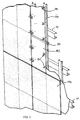
- FIG. 1 is a perspective view of the first stage of the cladding system.
- the cladding system starts with a support framework over the wall to be concealed.
- This framework includes a plurality of horizontally arranged steel channels or girts 10.
- On an exterior side of these girts 10 a plurality of mutually parallel vertically arranged channel members or "top hats" 20 are arranged.
- this moisture resistant barrier 30 is provided by a plurality of fibre cement sheets 40 fastened to top hats 20 however other moisture resistant barriers such as building paper or sarking etc can be used.
- the joints between these fibre reinforced cement sheets 40 may be sealed by appropriate horizontal flashing 50 and/or vertical flashing/jointing 60.
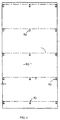
- the next step in the preferred cladding board construction is the positioning and attachments of mounting means to the framework to support the cladding boards.
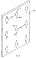
- a plurality of mounting brackets 70 is attached to this fibre reinforced cement sheet 40 as shown in figures 3 and 4.
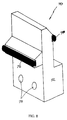
- the mounting bracket 70 preferably comprises a rigid bracket portion 72 with an interior resilient portion 74 and an exterior resilient portion 76.
- resilient portions 74, 76 are provided by rubber or other unitary elastomeric material.
- Other resilient means such as leaf or coil springs or spring clips may also be used.
- the rigid bracket portion 72 has aperture(s) 78 therethrough for passage of a screw, nail or other fastening means for attaching the mounting bracket to the framework.
- each mounting bracket 70 is fastened through the fibre reinforced cement sheet 40 to a top hat 20.
- the number and configuration of the mounting brackets 70 will depend on a number of factors including the size and weight of the cladding board to be supported thereon.
- a template may be used. This template is laid over the fibre reinforced cement sheet 40 and marked with appropriate positions for the mounting brackets 70.
- each level of the sheet 40 there are three mounting brackets on each level of the sheet 40. If desired, one can provide for more mounting brackets at the top, for particularly large cladding boards 100, and less at the bottom since the lower mounting brackets are essentially for wind loading only.
- the mounting brackets 70 at the lower end of each cladding board serve little function in the way of vertically supporting the cladding board. For example if the cladding board 100 was particularly large or wider an operator may determine that 5 or 6 mounting brackets were required at the top with a lower number eg 2 or 3 at the lower end.
- the inventive cladding board is shown in figure 5.
- the cladding board comprises board portion 100 having an exterior face 110 and interior face 120. Attached to the interior face 120 of the cladding board 100 is the support member 130.
- the support member(s) includes an engaging formation 132.
- This engaging formation 132 is preferably provided by a pair of mutually divergent recesses which, as will be discussed below, are configured to mate with an engaging formation in a mounting member.
- the engaging formation 132 is not formed or cut directly in the cladding board but instead is formed or cut in one or more support members 130 attached to the interior mounting face of the cladding board 100.
- support members 130 are provided in the form of a number of substantially parallel mutually spaced apart support strips.
- cutting or forming the engaging formation 132 directly in the board may affect the structural integrity of the board.
- any recesses or channels in the board itself may concentrate the stress applied to the cladding board along the line of the channel. This may lead to weakening or cracks appearing in the cladding board in the area of the channels or recesses.
- the structural integrity of the cladding board 100 is maintained and in fact reinforced. This arrangement reduces flexing of the cladding board 100 during handling. Even in the event of cracks appearing in the support members 130, these cracks do not propagate into the cladding board due to the laminated structure of the support member(s)/cladding board.
- the support member(s) may be formed from the same material as the cladding board or, alternatively, any other suitable material such as plastic, steel etc, however, aluminium is preferred.
- support members 130 may be fastened to the interior face 120 of the cladding board 100 by any appropriate mechanism such as gluing, mechanical fastening etc.
- Any appropriate mechanism such as gluing, mechanical fastening etc.
- One particularly preferred mechanism for attaching the support members 130 to the cladding board 100 is shown in figure 7.
- a series of blind or undercut keyhole slots 200 are formed in the interior face of the cladding board 100. These slots 200 have mutually opposed undercut portions 210 and 220 adapted to receive the small threaded disks or captive nuts 230. These threaded nuts or disks are adapted to engage with threaded fasteners 240. As shown more clearly in figure 6 these threaded fasteners 240 pass through support members 130 to engage the disk or nut 230 embedded in the cladding board and thereby hold the support member 130 flush against the interior face 120 of the cladding board 100. This mechanical attachment of the support members 130 to the cladding board may be assisted with glue. Preferably the fastening of the support members 130 to cladding board 100 is accomplished off-site and the cladding boards 100 are transported with the support members 130 in place.
- the support members 130 act to reinforce the cladding board to reduce flexure and damage during transportation and installation. They are also extremely useful for hanging the cladding board during painting.
- mounting members or splines 170 are slidably inserted into the support members 130 as shown in figure 5.
- the mounting members 170 include a first segment having an engaging formation 172 adapted to mate with the complementary engaging formation 132 in the support member 130.
- the engaging formation of the mounting member is a V cross-sectional channel 172 configured to engage the pair of mutually divergent recesses 132 formed in the support member 130.
- the second segment of the mounting member 170 is a downwardly directed extension 174 to releasably engage the mounting brackets 70.
- the support members 130 and/or mounting members 170 preferably extend substantially across the entire width of the cladding board. Once the mounting members 170 are in position in the support members 130, the ends of the support members 130 may be crimped or sealed to prevent the mounting members 170 from sliding out.
- packing material may be provided on the top edge of an already mounted cladding board, so that the cladding board to be mounted is lifted onto the mounting brackets 70 directly above and lowered to contact the packing material. This ensures the cladding board to be mounted is parallel with the cladding board directly below.
- the resilient portions 74, 76 which are deformable, are arranged to abut the support member 130 or cladding board 100 on an exterior side and the mounting member 170 on an interior side.
- the mounting bracket 70 and resilient gripping means 74, 76 are arranged to hold and support the cladding board but allow limited movement of the cladding board 100 relative to the surface to be concealed. Preferably there is no contact between the mounting bracket 70 and the support member 130 or mounting member 170 other than through resilient portions 74, 76. This allows the cladding board to "float" on the mounting brackets since there is no abutment of the rigid bracket portion 72 on the mounting member 170 or support member 130.
- the preferred arrangement for the resilient portion 74 and 76 shown in figure 6 is to offset these portions in the direction of load of the cladding board 100 on the brackets 70. This configuration allows the cladding board to move in a direction parallel to the surface to be concealed. By action of the load of the cladding board on the resilient portion 74, 76 the cladding board is held in its new position.
- Such an arrangement has several advantages. Firstly, it allows the position of the cladding board 100 to be altered slightly to make up for any minor misalignment of the cladding board system. Further, the resilient portions 74, 76 act as a shock absorber for the cladding board. To explain, on the exterior of the building, the cladding boards 100 may be exposed to high wind, rain and other natural forces. The cladding boards 100 will move in response to these natural forces. If the cladding board 100 is rigidly attached to the mounting brackets 70, any flexure of the cladding board may cause damage.
- the present inventive resilient portions 74, 76 between the mounting brackets 70 and cladding board 100 vibratory movement of the cladding board toward and away from the surface to be concealed or movement in the plane of the board is dampened somewhat by these resilient portions 74, 76 thereby reducing the possibility of damage to the cladding board.
- the support strips 130 and mounting members 170 which extend across the entire width of the cladding board, also reduce flexure of the cladding board in situ.
- the arrangement also allows the board 100 to move in situ, to a limited extent and relative to the surface to be concealed, on the mounting brackets 70 to relieve any internal stresses acting on the board.
- the uppermost mounting member 170 of each cladding board comprises an additional upstanding portion 180.
- This upstanding portion 180 is adapted to be attached to the top hats 20 through fibre cement sheet 40.
- This upstanding portion 180 serves several purposes. Firstly, it is used to provide additional support for the cladding board and correctly position and fix the cladding board 100 to the top hats 20. It also provides a horizontal flashing portion 190 to substantially seal the gap between vertically adjacent cladding boards, as shown in figure 6.
- vertical and horizontal flashing may be positioned between the just mounted cladding board and the surrounding boards. This flashing reduces water ingress behind the cladding board and helps to stop vermin entering the space between the fibre cement water resistant layer 30 and the cladding boards 100. Since it is possible to adjust the position of the cladding board 100 prior to fixing the upstanding mounting portion 180, it is possible to mechanically seal or flash the various joints between the cladding boards. Conventional cladding systems use sealants or gaskets which tend to degrade or fail after a few years when exposed to the elements.
- the cladding board may be moved on the mounting bracket 70 until fixed via upstanding mounting portion 180, it is possible to manipulate the position of the board so that it abuts the mechanical flashing thereby providing a long lasting vermin and moisture resistant barrier which will not degrade to anywhere near the extent of conventional sealants or gaskets.
- the cladding boards 100 are mounted offset relative to the fibre cement water resistant sheets 40. By offsetting the joins of the cladding boards 100 with the sheets 40, it is more difficult for water to pass between both the cladding boards 100 and fibre cement sheets 40 toward the steel girts 10 and top hats 20.
- the support members 130 and mounting members 170 extend substantially horizontally. Equally these support members and mounting members may be positioned vertically or diagonally to support cladding boards 100.
- both the support member 130 and mounting member 170 extend substantially across the entire width of the cladding board 100.
- the cladding board 100 may include a plurality of support members extending only part way across the cladding board or even individual support members each positioned to releasably engage a matching number of mounting brackets 70 via a respective mounting members 170.
- the mounting member 170 may be provided to extend substantially across the entire width of the cladding board 100 and engage a plurality of substantially colinear support members spaced across the cladding board.
- the cladding boards may painted or covered with any particular finish desired.
- the cladding boards are constructed from fibre reinforced cement (frc).
- the frc cladding boards allow for a greater range of finishes than do conventional wooden or metal cladding sheets.
Landscapes
- Architecture (AREA)
- Engineering & Computer Science (AREA)
- Civil Engineering (AREA)
- Structural Engineering (AREA)
- Physics & Mathematics (AREA)
- Electromagnetism (AREA)
- Finishing Walls (AREA)
- Paper (AREA)
- Auxiliary Devices For And Details Of Packaging Control (AREA)
- Mounting Of Printed Circuit Boards And The Like (AREA)
- Combinations Of Printed Boards (AREA)
- Laminated Bodies (AREA)
- Connection Of Plates (AREA)
- Manufacturing Of Printed Wiring (AREA)
- Reinforced Plastic Materials (AREA)
- Forklifts And Lifting Vehicles (AREA)
- Mechanical Coupling Of Light Guides (AREA)
- Load-Bearing And Curtain Walls (AREA)
- Conveying And Assembling Of Building Elements In Situ (AREA)
Abstract
Description
Claims (18)
- A cladding board mounting system for mounting cladding boards adjacent to a surface to be concealed, said system comprising:at least one support member (130) adapted to be attached to an interior mounting face (120) of said cladding board (100), andat least one mounting member (170) being adapted for releasable connection to the surface to be concealed, wherebysaid at least one mounting member (170) includes a first segment having an engaging formation (172) adapted for releasable engagement with a complementary engaging formation (132) in a respective one of said support member(s) (130), and a second segment (174) of the mounting member (170) being adapted for releasable connection to the surface to be concealed, characterised in that:the first segment of each mounting member (170) has a V cross-sectional shaped channel (172) adapted to slidably engage a pair of mutually divergent recesses (132) formed in the respective support member (130).
- A cladding board mounting system as claimed in claim 1 wherein each support member (130) is formed by a substantially two-dimensional support layer adapted to be attached to the interior mounting face of the cladding board (100).
- A cladding board mounting system as claimed in claim 2 wherein the support layer substantially covers the entire interior mounting face (120) of the cladding board (100).
- A cladding board mounting system as claimed in claim 1 or claim 2 wherein each support member (130) comprises a strip extending substantially across the entire width of the cladding board.
- A cladding board mounting system as claimed in any one of the previous claims wherein the second segment (174) of each mounting member (170) comprises a downwardly extending portion configured to facilitate releasable connection of the mounting member (170) to the surface to be concealed.
- A cladding board mounting system as claimed in claim 6 wherein at least one of the mounting members (170) includes an additional extended portion (180) for fixed attachment to the surface to be concealed.
- A cladding board mounting system as claimed in any one of the previous claims further including a plurality of mounting brackets (70) adapted to be attached to the surface to be concealed, each mounting bracket (70) providing a recess for releasable engagement with the mounting member (170).
- A cladding board mounting system as claimed in any one of the previous claims wherein a resilient mounting means (70) is provided between the cladding board (100) and the surface to be concealed.
- A cladding board mounting system as claimed in claim 8 wherein the resilient mounting means (70) is adapted to permit limited relative movement between the cladding board (100) and the surface to be concealed.
- A cladding board mounting system as claimed in claim 8 or claim 9 wherein the resilient mounting (70) means comprises a rigid mounting bracket (72) adapted to be attached to the surface to be concealed with an exterior resilient portion (76) adapted to abut the support member (130) or cladding board (100), and an interior resilient portion (74) adapted to abut the second segment (174) of the mounting member (170).
- A cladding board mounting system as claimed in claim 10 wherein said interior and exterior resilient portions (74, 76) are offset in the direction of load of the cladding board on the brackets (72).
- A cladding board mounting system as claimed in claim 10 or 11 wherein the exterior resilient portion (76) is vertically offset below the interior resilient portion (74).
- A cladding board mounting system as claimed in any one of the previous claims wherein each support member (130) is attached to the cladding board (100) by a plurality of discrete fastening means (240) positioned across the width of the cladding board (100) and partially embedded in the cladding board (100).
- A cladding board mounting system according to claim 13 wherein undercut key hole slots (200) are formed in the interior face (120) of the cladding board (100) for captively retaining a portion of said discrete fastening means (240).
- A cladding board mounting system according to claim 14 wherein said captively retained portion of the fastening means (240) comprises internally threaded nuts or discs (230) adapted to be inserted into said key hole slots (200) and engage corresponding externally threaded fasteners (240) that interact with the support member (130) to secure it to the cladding board (100).
- A cladding board mounting system as claimed in any one of the preceding claims wherein the cladding board (100) is constructed from fibre reinforced cement.
- A cladding board mounting system as claimed in any one of the preceding claims wherein each support member (130) and mounting member (170) extends, in use, generally horizontally relative to the surface to be clad.
- A cladding board mounting system according to any one of the previous claims wherein the support member (130) is attached to the cladding board (100) with adhesive.
Priority Applications (1)
| Application Number | Priority Date | Filing Date | Title |
|---|---|---|---|
| EP02080564A EP1296004B1 (en) | 1996-09-05 | 1997-09-05 | A cladding board mounting system |
Applications Claiming Priority (3)
| Application Number | Priority Date | Filing Date | Title |
|---|---|---|---|
| AUPO215996 | 1996-09-05 | ||
| AUPO2159A AUPO215996A0 (en) | 1996-09-05 | 1996-09-05 | An improved cladding board mounting system |
| PCT/AU1997/000582 WO1998010151A1 (en) | 1996-09-05 | 1997-09-05 | An improved cladding board mounting system |
Related Child Applications (1)
| Application Number | Title | Priority Date | Filing Date |
|---|---|---|---|
| EP02080564A Division EP1296004B1 (en) | 1996-09-05 | 1997-09-05 | A cladding board mounting system |
Publications (3)
| Publication Number | Publication Date |
|---|---|
| EP0943041A1 EP0943041A1 (en) | 1999-09-22 |
| EP0943041A4 EP0943041A4 (en) | 1999-12-01 |
| EP0943041B1 true EP0943041B1 (en) | 2003-05-21 |
Family
ID=3796472
Family Applications (2)
| Application Number | Title | Priority Date | Filing Date |
|---|---|---|---|
| EP02080564A Expired - Lifetime EP1296004B1 (en) | 1996-09-05 | 1997-09-05 | A cladding board mounting system |
| EP97937362A Expired - Lifetime EP0943041B1 (en) | 1996-09-05 | 1997-09-05 | An improved cladding board mounting system |
Family Applications Before (1)
| Application Number | Title | Priority Date | Filing Date |
|---|---|---|---|
| EP02080564A Expired - Lifetime EP1296004B1 (en) | 1996-09-05 | 1997-09-05 | A cladding board mounting system |
Country Status (21)
| Country | Link |
|---|---|
| US (1) | US6226947B1 (en) |
| EP (2) | EP1296004B1 (en) |
| JP (2) | JP3716996B2 (en) |
| KR (1) | KR100415501B1 (en) |
| CN (1) | CN1229450A (en) |
| AT (2) | ATE241054T1 (en) |
| AU (1) | AUPO215996A0 (en) |
| CA (1) | CA2264909C (en) |
| CZ (1) | CZ71599A3 (en) |
| DE (2) | DE69735449T2 (en) |
| DK (1) | DK0943041T3 (en) |
| ES (2) | ES2260390T3 (en) |
| HU (1) | HUP9904036A2 (en) |
| ID (1) | ID17333A (en) |
| IL (1) | IL128787A0 (en) |
| NZ (1) | NZ334899A (en) |
| PL (2) | PL193842B1 (en) |
| SK (1) | SK28599A3 (en) |
| TR (2) | TR199902892T2 (en) |
| TW (1) | TW340156B (en) |
| WO (1) | WO1998010151A1 (en) |
Families Citing this family (101)
| Publication number | Priority date | Publication date | Assignee | Title |
|---|---|---|---|---|
| US6689451B1 (en) | 1999-11-19 | 2004-02-10 | James Hardie Research Pty Limited | Pre-finished and durable building material |
| CA2299488A1 (en) * | 2000-02-24 | 2001-08-24 | Ofis Systems Inc. | Modular partition system |
| US6539643B1 (en) | 2000-02-28 | 2003-04-01 | James Hardie Research Pty Limited | Surface groove system for building sheets |
| US6745531B1 (en) * | 2000-07-31 | 2004-06-08 | Construction Research & Technology Gmbh | Pressure equalized compartment for exterior insulation and finish system |
| MXPA03009029A (en) | 2001-04-03 | 2004-02-12 | James Hardie Res Pty Ltd | Spline for siding planks, methods of making and installing. |
| US20030208973A1 (en) * | 2001-11-02 | 2003-11-13 | Corden David A. | Free-standing panel wall system |
| US6601349B1 (en) * | 2001-11-02 | 2003-08-05 | David A. Corden | Free-standing panel wall system |
| MXPA02000853A (en) * | 2002-01-23 | 2003-07-30 | De Leon Fierro Rigoberto | Walls with mortised tiles and metallic structure for multiple uses such as floors, walls and gradins. |
| JP4406360B2 (en) | 2002-07-16 | 2010-01-27 | ジェイムズ ハーディー インターナショナル ファイナンス ベスローテン フェンノートシャップ | Packaging of prefinished fiber cement products |
| US8281535B2 (en) | 2002-07-16 | 2012-10-09 | James Hardie Technology Limited | Packaging prefinished fiber cement articles |
| MXPA05003691A (en) | 2002-10-07 | 2005-11-17 | James Hardie Int Finance Bv | Durable medium-density fibre cement composite. |
| CN100430566C (en) * | 2002-12-19 | 2008-11-05 | 荷兰亨特工业有限公司 | Panel system |
| KR100401162B1 (en) * | 2003-02-22 | 2003-10-10 | Young Bok Lee | Structure for mounting interior panel |
| GB2403229B (en) * | 2003-06-25 | 2007-02-28 | Shackerley | Sureclad |
| AU2003267369B2 (en) * | 2003-09-16 | 2010-03-04 | Renovision Ingenieurgesellschaft Fuer Fenster Und Fassade Mbh | Supporting framework for a facade |
| ES2257143B1 (en) * | 2004-02-05 | 2007-08-16 | Wadegar 2001, S.L. | HIDDEN FIXING SYSTEM FOR FACADES WITH RIGID COATING. |
| US7998571B2 (en) | 2004-07-09 | 2011-08-16 | James Hardie Technology Limited | Composite cement article incorporating a powder coating and methods of making same |
| CN100453757C (en) * | 2005-05-19 | 2009-01-21 | 凌小平 | Construction method for direct dry-hanging stone for wall |
| US8689509B2 (en) | 2006-02-03 | 2014-04-08 | James Hardie Technology Limited | Expressed joint facade system |
| ES1062160Y (en) * | 2006-02-08 | 2006-08-16 | Frons Ventilo S A | DEVICE FOR FIXING ELEMENTS OF SMALL THICKNESS IN FACADES. |
| WO2007115379A1 (en) | 2006-04-12 | 2007-10-18 | James Hardie International Finance B.V. | A surface sealed reinforced building element |
| DE102006033045A1 (en) * | 2006-07-14 | 2008-01-17 | Moeding Keramikfassaden Gmbh | Curtain wall construction |
| US8695303B2 (en) * | 2007-07-06 | 2014-04-15 | Top Down Siding, Llc | Panels including trap lock adaptor strips |
| WO2008101319A1 (en) * | 2007-02-19 | 2008-08-28 | Dmytro Lysyuk | Apparatus and method for installing cladding to structures |
| DE102007008829B4 (en) | 2007-02-20 | 2022-01-27 | Röhl GmbH Verbundelemente | mounting arrangement |
| WO2008106735A1 (en) | 2007-03-08 | 2008-09-12 | James Hardie International Finance B.V. | Building system |
| NZ579719A (en) | 2007-03-21 | 2012-08-31 | Hardie James Technology Ltd | Drainage panel for a framed wall construction with a water resistant surface and drainage channels |
| US20090025327A1 (en) * | 2007-03-26 | 2009-01-29 | Albracht Gregory P | Furring Strip Alignment System |
| CA2683279A1 (en) * | 2007-05-17 | 2008-11-27 | Kingspan Holdings (Irl) Limited | A support system for mounting building facade elements to a framework |
| USD742552S1 (en) | 2007-07-06 | 2015-11-03 | Top Down Siding, Llc | Front face of a building siding panel |
| SI22633B (en) * | 2007-09-24 | 2013-02-28 | Trimo D.D. | Fastening of prefabricated building elements |
| US20090094926A1 (en) * | 2007-10-11 | 2009-04-16 | Richmond David E | System and method of repaneling a structure |
| WO2009059392A1 (en) * | 2007-11-08 | 2009-05-14 | Lysyuk, Dmytro | Apparatus and method for installing cladding to structures |
| GB0722231D0 (en) * | 2007-11-13 | 2007-12-27 | Protean Design Ltd | Panel mounting system |
| ES2338192B1 (en) * | 2007-12-13 | 2011-03-28 | Eclad Limited | ANCHOR SYSTEM OF VENTILATED FACADES. |
| AU320072S (en) | 2008-03-07 | 2008-06-30 | Hardie James Technology Ltd | Building element |
| AU320071S (en) | 2008-03-07 | 2008-06-30 | Hardie James Technology Ltd | Building element |
| WO2009153767A1 (en) * | 2008-06-20 | 2009-12-23 | Kingspan Research And Developments Limited | A facade system |
| US20090313935A1 (en) * | 2008-06-24 | 2009-12-24 | Environmental Interiors, Inc. | High Impact, Moisture Resistant Wall Panel System |
| WO2010012061A1 (en) * | 2008-07-28 | 2010-02-04 | Dmytro Romanovich Lysyuk | Clip and support for installing cladding |
| US8061101B2 (en) * | 2008-09-12 | 2011-11-22 | Progressive Foam Technologies, Inc. | Insulating siding system |
| US20100170181A1 (en) * | 2008-09-17 | 2010-07-08 | William Dale Nichols | Protective shield assembly |
| WO2010040225A1 (en) * | 2008-10-08 | 2010-04-15 | Tyler Matys | Facing element and method of fabricating thereof |
| US8322103B1 (en) * | 2008-10-22 | 2012-12-04 | Charles D Kownacki | Faux brick with suspension system |
| WO2010075104A2 (en) * | 2008-12-15 | 2010-07-01 | Mohawk Carpet Corporation | Tile systems and methods of making and using same |
| AU326890S (en) | 2009-05-29 | 2009-07-27 | Hardie James Technology Ltd | Building element |
| AU326889S (en) | 2009-05-29 | 2009-07-27 | Hardie James Technology Ltd | Building element |
| ES2657612T3 (en) | 2010-05-28 | 2018-03-06 | The Diller Corporation | Laminate coating system for construction |
| US8474214B2 (en) * | 2011-01-26 | 2013-07-02 | Nissan North America, Inc. | Connecting structure for automotive trim panels |
| US8621810B2 (en) | 2011-02-28 | 2014-01-07 | Kingspan Insulated Panels, Inc. (USA) | Building wall system |
| NZ592576A (en) * | 2011-04-29 | 2013-09-27 | Jenkin Timber Ltd | A fixing system for cladding and a cladded structure |
| US9080331B2 (en) * | 2011-05-31 | 2015-07-14 | Charbel Tannious Aboukhalil | Universal architectural system |
| CN102287037A (en) * | 2011-06-20 | 2011-12-21 | 山东宁建建设集团有限公司 | Large-area back-bolt ceramic tile dry hanging construction method |
| US20130014636A1 (en) * | 2011-07-08 | 2013-01-17 | Tejav Dehghanyar | Blast absorbing cladding |
| US20130205695A1 (en) * | 2011-12-07 | 2013-08-15 | Brian Geofrey Newell | Access |
| GB2497796A (en) * | 2011-12-21 | 2013-06-26 | Hardie James Technology Ltd | Thermally Efficient Façade |
| CA2784018C (en) * | 2012-07-26 | 2019-12-24 | Engineered Assemblies Inc. | Thermal clip system and apparatus for a building wall assembly |
| WO2014043805A1 (en) * | 2012-09-20 | 2014-03-27 | Oldcastle Building Products Canada Inc. | Panel with compressible projections and masonry wall system including the panel |
| US9499978B2 (en) | 2012-10-03 | 2016-11-22 | Kingspan Insulated Panels, Inc. | Building wall panel |
| DE102012221746B4 (en) * | 2012-11-28 | 2023-03-23 | T4 Systems Umwelttechnik Gmbh | wall heating element |
| US9032682B2 (en) * | 2012-12-10 | 2015-05-19 | Target Brands, Inc. | Free-standing wall |
| US9140007B2 (en) * | 2013-04-23 | 2015-09-22 | MOTO Extrusions, Inc. | Rain screen framing system |
| US9140008B2 (en) * | 2013-04-23 | 2015-09-22 | MOTO Extrusions, Inc. | Multi-layered cladding frame system |
| WO2015006390A1 (en) * | 2013-07-09 | 2015-01-15 | Firestone Building Products Company, Llc | Non-sequentially installed dry joint wall panel system |
| US9745739B2 (en) * | 2014-02-25 | 2017-08-29 | Breton Systems Llc | Wall construction method using injected urethane foam between the wall and autoclaved concrete (AAC) blocks |
| US9163399B1 (en) * | 2014-04-17 | 2015-10-20 | Brandon Kelley | Storefront cladding system |
| US9976311B2 (en) * | 2015-02-10 | 2018-05-22 | James Reid Gulnick | Attachment brackets for panel mounting |
| US9469999B1 (en) * | 2015-04-30 | 2016-10-18 | Wall Panel Systems, Inc. | Exterior wall panneling system |
| US9938725B2 (en) | 2015-05-04 | 2018-04-10 | Kingspan Insulated Panels, Inc. | Building panel |
| US9464442B1 (en) * | 2015-08-13 | 2016-10-11 | Stone Master Sa | Wall cladding assembly method and system |
| CN105064645B (en) * | 2015-08-31 | 2017-12-22 | 湖南安雅达建材科技有限公司 | A kind of wallboard erecting device |
| PL232498B1 (en) | 2016-06-10 | 2019-06-28 | Wido Profil Spolka Z Ograniczona Odpowiedzialnoscia | Non-anchor system for fixing panel cladding elements and method for fixing it |
| US10081941B2 (en) * | 2016-06-21 | 2018-09-25 | Fry Reglet Corporation | Wall cladding system and method |
| RU2754687C2 (en) * | 2016-06-30 | 2021-09-06 | Кнауф Гипс Кг | Plasterboard construction system with spring rail |
| TWI576492B (en) * | 2016-07-21 | 2017-04-01 | Jing-Lun Lin | Metal plate positioning structure |
| US10407917B1 (en) | 2017-04-17 | 2019-09-10 | Henry H. Bilge | System for mounting wall panels to a wall |
| US10787817B1 (en) | 2017-04-17 | 2020-09-29 | Henry H. Bilge | System for mounting adjustable covering panels to a wall |
| US10253507B1 (en) * | 2017-04-17 | 2019-04-09 | Henry H. Bilge | System for mounting wall panels to a wall |
| US10260240B1 (en) * | 2017-04-17 | 2019-04-16 | Henry H. Bilge | System for mounting wall panels to a wall |
| US12435518B2 (en) * | 2019-01-30 | 2025-10-07 | Dirtt Environmental Solutions Ltd. | Magnesium-oxide wall tiles for modular wall systems |
| PL428848A1 (en) * | 2019-02-08 | 2020-08-10 | Wido-Profil Spółka Z Ograniczoną Odpowiedzialnością | Hanger and its mounting to the cladding board |
| DE102019105794A1 (en) * | 2019-03-07 | 2020-09-10 | kubix Gesellschaft für Entwicklung und Produktion temporärer Bauten mbH | Wall construction, in particular for trade fair or museum construction, and method for setting up the wall construction |
| CN110056148B (en) * | 2019-05-23 | 2023-12-22 | 金螳螂精装科技(苏州)有限公司 | An assembled dry-hanging installation structure for small-sized ceramic tiles |
| CN110485670B (en) * | 2019-09-09 | 2024-07-19 | 苏州美瑞德建筑装饰有限公司 | Anti-deformation curved surface form wall panel mounting structure and mounting method thereof |
| US10900239B1 (en) * | 2019-09-24 | 2021-01-26 | Henry H. Bilge | System for mounting wall panels to an existing wall |
| RU195612U1 (en) * | 2019-11-08 | 2020-02-03 | Ярослав Владимирович Григорьев | Guiding horizontal steel profile of a ventilated facade system |
| JP7538686B2 (en) | 2019-12-02 | 2024-08-22 | ケイミュー株式会社 | Building board mounting fixture and renovation structure using same |
| US11396749B2 (en) * | 2020-01-21 | 2022-07-26 | Mitek Holdings, Inc. | Exterior wall system |
| US11162265B2 (en) * | 2020-04-06 | 2021-11-02 | Fero Corporation | Support bracket assembly and method |
| CN112092117B (en) * | 2020-08-28 | 2022-05-13 | 广西大学 | Preparation method of crossed grid oriented light plate |
| IL279891A (en) | 2020-12-30 | 2022-07-01 | Yochanan Grosswirth | Wall covering installation system |
| US11519180B2 (en) * | 2021-03-11 | 2022-12-06 | Henry H. Bilge | System for mounting wall panels onto a wall or floor slabs |
| WO2022264276A1 (en) * | 2021-06-15 | 2022-12-22 | 晋 佐藤 | Wall panel unit and method for installing wall panel unit |
| EP4119003B1 (en) * | 2021-07-15 | 2024-09-11 | Navona GmbH & Co. KG | Furnishing item and its use |
| KR102739470B1 (en) * | 2022-03-03 | 2024-12-06 | 주식회사 유토 | System for dry execution of finishing material |
| US12286798B2 (en) * | 2022-06-24 | 2025-04-29 | Blox, Llc | Three axis clip system for mounting panels to a wall |
| MX2024000569A (en) * | 2022-07-26 | 2024-02-13 | Bkuep Mimarlik Anonim Sirketi | A ventilated facade cladding system. |
| CN115653170B (en) * | 2022-09-08 | 2025-04-25 | 中亿丰建设集团股份有限公司 | A unit curtain wall system with vertical open stone lines and its installation process |
| US20240263456A1 (en) * | 2023-02-07 | 2024-08-08 | Highland Park Technologies, LLC | Building insulation and cladding system |
| KR102669133B1 (en) * | 2023-07-07 | 2024-05-27 | (주)민예 | Wall Structure Using Stone And Insulation Panel Unit For The Preventing Spread Of Fire |
| CN118997372B (en) * | 2024-10-10 | 2025-03-18 | 吉祥佳利铝业江苏有限公司 | A multi-stage connection structure of curtain wall aluminum veneer |
Family Cites Families (24)
| Publication number | Priority date | Publication date | Assignee | Title |
|---|---|---|---|---|
| AT339011B (en) | 1975-07-07 | 1977-09-26 | Leitl Werke Bauhuette | BUILDING WALL, IN PARTICULAR FACADE CONSTRUCTION MADE OF PLATE SHAPED, E.G. CERAMIC COMPONENTS |
| US4187658A (en) * | 1976-05-20 | 1980-02-12 | Illinois Tool Works Inc. | Panel clamp |
| GB1577648A (en) * | 1977-03-04 | 1980-10-29 | Sadacem | Curtain wall structure |
| US4307551A (en) * | 1979-08-09 | 1981-12-29 | Ppg Industries, Inc. | System for cladding building exteriors |
| DE3001278A1 (en) * | 1980-01-15 | 1981-07-30 | Annawerk Gmbh | CERAMIC PANEL FACADE |
| FR2522049A1 (en) | 1982-02-25 | 1983-08-26 | Guerin Gabriel | DEVICE FOR FASTENING A STONE PLATE COATING RECONSTITUTED ON A WALL STRUCTURE |
| DE3505335C2 (en) | 1985-02-15 | 1996-01-18 | Gruenzweig & Hartmann Montage | Wall cladding |
| US4685263A (en) * | 1986-05-23 | 1987-08-11 | Ting Raymond M L | Aluminum plate curtain wall structure |
| SE457935B (en) | 1987-07-08 | 1989-02-13 | Seco Tools Ab | TOOLS FOR CUTTING PROCESSING AND CUTTING BEFORE TOOLS |
| JPS6422385A (en) | 1987-07-16 | 1989-01-25 | Showa Denko Kk | Method of bonding screen |
| JPS6425200A (en) | 1987-07-22 | 1989-01-27 | Hitachi Ltd | Voice synthesization system |
| US4866896A (en) * | 1988-04-26 | 1989-09-19 | Construction Specialties, Inc. | Panel wall system |
| EP0378726A1 (en) | 1989-01-20 | 1990-07-25 | Bruno Kurmann | Device for fastening façade elements |
| US4995215A (en) * | 1989-01-23 | 1991-02-26 | National Gypsum Company | Panels with laminated strips for clips |
| CA1329690C (en) * | 1989-02-22 | 1994-05-24 | Michael Sommerstein | Panel mounting clip |
| DE3923800A1 (en) | 1989-07-15 | 1991-01-24 | Montaflex Aluminiumprofile & B | Attachment of facade of ceramic tiles - using specially shaped brackets which fit over support rail |
| DE69107066T2 (en) | 1990-03-12 | 1995-08-03 | Gns Uk Ltd | FASTENING DEVICE. |
| US5155958A (en) * | 1991-10-17 | 1992-10-20 | Huff James C | Fastening and support system for architectural panels |
| SE505797C2 (en) | 1991-12-30 | 1997-10-13 | Nils Gunnar Jansson | Apparatus for setting up facade elements of glass |
| DE4209834C2 (en) | 1992-03-26 | 1996-04-04 | Dieter Brich | Glass facade on a supporting structure |
| DE9307530U1 (en) * | 1993-05-18 | 1994-09-29 | STO Verotec GmbH, 89415 Lauingen | Facade panel |
| DE9416917U1 (en) | 1994-10-20 | 1994-12-01 | Hoechst Ag, 65929 Frankfurt | Fastening system for compact panels |
| US5598671A (en) * | 1995-02-09 | 1997-02-04 | Ting; Raymond M. L. | Externally drained wall joint |
| AUPN731795A0 (en) | 1995-12-22 | 1996-01-25 | James Hardie Research Pty Limited | A cladding board mounting system |
-
1996
- 1996-09-05 AU AUPO2159A patent/AUPO215996A0/en not_active Abandoned
-
1997
- 1997-09-04 TW TW086112781A patent/TW340156B/en not_active IP Right Cessation
- 1997-09-05 DE DE69735449T patent/DE69735449T2/en not_active Expired - Lifetime
- 1997-09-05 DE DE69722241T patent/DE69722241T2/en not_active Expired - Lifetime
- 1997-09-05 TR TR1999/02892T patent/TR199902892T2/en unknown
- 1997-09-05 NZ NZ334899A patent/NZ334899A/en not_active IP Right Cessation
- 1997-09-05 ES ES02080564T patent/ES2260390T3/en not_active Expired - Lifetime
- 1997-09-05 CN CN97197698A patent/CN1229450A/en active Pending
- 1997-09-05 WO PCT/AU1997/000582 patent/WO1998010151A1/en not_active Ceased
- 1997-09-05 US US09/254,462 patent/US6226947B1/en not_active Expired - Lifetime
- 1997-09-05 HU HU9904036A patent/HUP9904036A2/en unknown
- 1997-09-05 PL PL97378646A patent/PL193842B1/en not_active IP Right Cessation
- 1997-09-05 JP JP51205998A patent/JP3716996B2/en not_active Expired - Fee Related
- 1997-09-05 IL IL12878797A patent/IL128787A0/en unknown
- 1997-09-05 SK SK285-99A patent/SK28599A3/en unknown
- 1997-09-05 EP EP02080564A patent/EP1296004B1/en not_active Expired - Lifetime
- 1997-09-05 ES ES97937362T patent/ES2200191T3/en not_active Expired - Lifetime
- 1997-09-05 DK DK97937362T patent/DK0943041T3/en active
- 1997-09-05 AT AT97937362T patent/ATE241054T1/en not_active IP Right Cessation
- 1997-09-05 CZ CZ99715A patent/CZ71599A3/en unknown
- 1997-09-05 TR TR1999/00906T patent/TR199900906T2/en unknown
- 1997-09-05 CA CA002264909A patent/CA2264909C/en not_active Expired - Fee Related
- 1997-09-05 AT AT02080564T patent/ATE320535T1/en not_active IP Right Cessation
- 1997-09-05 KR KR10-1999-7001825A patent/KR100415501B1/en not_active Expired - Fee Related
- 1997-09-05 EP EP97937362A patent/EP0943041B1/en not_active Expired - Lifetime
- 1997-09-05 ID IDP973099A patent/ID17333A/en unknown
- 1997-09-05 PL PL97332039A patent/PL193826B1/en not_active IP Right Cessation
-
2005
- 2005-06-08 JP JP2005168289A patent/JP4035137B2/en not_active Expired - Fee Related
Also Published As
Similar Documents
| Publication | Publication Date | Title |
|---|---|---|
| US6226947B1 (en) | Cladding board mounting system | |
| US5136823A (en) | Device for cladding architectural shingles | |
| US20070107328A1 (en) | Panel attachment system | |
| AU2010100532A4 (en) | Expressed joint facade system | |
| US20120174503A1 (en) | Building system with multi-function insulation barrier | |
| US20130312347A1 (en) | Building system with multi-function insulation barrier | |
| US20190316352A1 (en) | Wall/Roof Construction System and Related Method | |
| US4479339A (en) | Cover member for and method of installing insulation boards | |
| US4731972A (en) | Method of installing fabric wall panels | |
| EP3789557B1 (en) | Kit for providing a roof light system comprising a roof module, a ceiling module and a shaft arrangement, and a method of installing a roof light system in a roof | |
| US4646501A (en) | Starter bracket for installing aluminum siding | |
| AU722347C (en) | An improved cladding board mounting system | |
| AU722347B2 (en) | An improved cladding board mounting system | |
| US20210164234A1 (en) | Clip for cast stone wall system | |
| HK1021006B (en) | An improved cladding board mounting system | |
| AU729806B2 (en) | An improved cladding board mounting system | |
| US20110192102A1 (en) | System for Concealed Fastening of Building Finishing Elements | |
| US20240035286A1 (en) | Building surface product including embedded fastener, building surface system, and method of manufacture | |
| HK1051392B (en) | A cladding board mounting system | |
| US4606160A (en) | Plaster backing panel for ventilated curtain wall system | |
| GB2240123A (en) | Building panels | |
| AU2021106901A4 (en) | Fixing of battens to a substructure | |
| CN109930945B (en) | Mounting method of hidden auxiliary sleeve | |
| AU2011202644A1 (en) | Expressed joint facade system |
Legal Events
| Date | Code | Title | Description |
|---|---|---|---|
| PUAI | Public reference made under article 153(3) epc to a published international application that has entered the european phase |
Free format text: ORIGINAL CODE: 0009012 |
|
| 17P | Request for examination filed |
Effective date: 19990316 |
|
| AK | Designated contracting states |
Kind code of ref document: A1 Designated state(s): AT BE CH DE DK ES FI FR GB GR IE IT LI LU MC NL PT SE |
|
| A4 | Supplementary search report drawn up and despatched |
Effective date: 19991018 |
|
| AK | Designated contracting states |
Kind code of ref document: A4 Designated state(s): AT BE CH DE DK ES FI FR GB GR IE IT LI LU MC NL PT SE |
|
| 17Q | First examination report despatched |
Effective date: 20020205 |
|
| GRAH | Despatch of communication of intention to grant a patent |
Free format text: ORIGINAL CODE: EPIDOS IGRA |
|
| GRAH | Despatch of communication of intention to grant a patent |
Free format text: ORIGINAL CODE: EPIDOS IGRA |
|
| GRAA | (expected) grant |
Free format text: ORIGINAL CODE: 0009210 |
|
| AK | Designated contracting states |
Designated state(s): AT BE CH DE DK ES FI FR GB GR IE IT LI LU MC NL PT SE |
|
| REG | Reference to a national code |
Ref country code: GB Ref legal event code: FG4D |
|
| REG | Reference to a national code |
Ref country code: CH Ref legal event code: EP |
|
| BECA | Be: change of holder's address |
Owner name: JAMES *HARDIE RESEARCH PTY. LTDLEVELL, RESEARCH & Effective date: 20030521 |
|
| REG | Reference to a national code |
Ref country code: IE Ref legal event code: FG4D |
|
| REF | Corresponds to: |
Ref document number: 69722241 Country of ref document: DE Date of ref document: 20030626 Kind code of ref document: P |
|
| PG25 | Lapsed in a contracting state [announced via postgrant information from national office to epo] |
Ref country code: PT Free format text: LAPSE BECAUSE OF FAILURE TO SUBMIT A TRANSLATION OF THE DESCRIPTION OR TO PAY THE FEE WITHIN THE PRESCRIBED TIME-LIMIT Effective date: 20030821 Ref country code: GR Free format text: LAPSE BECAUSE OF FAILURE TO SUBMIT A TRANSLATION OF THE DESCRIPTION OR TO PAY THE FEE WITHIN THE PRESCRIBED TIME-LIMIT Effective date: 20030821 |
|
| RAP2 | Party data changed (patent owner data changed or rights of a patent transferred) |
Owner name: JAMES HARDIE RESEARCH PTY LIMITED |
|
| PG25 | Lapsed in a contracting state [announced via postgrant information from national office to epo] |
Ref country code: LU Free format text: LAPSE BECAUSE OF NON-PAYMENT OF DUE FEES Effective date: 20030905 |
|
| REG | Reference to a national code |
Ref country code: SE Ref legal event code: TRGR |
|
| REG | Reference to a national code |
Ref country code: CH Ref legal event code: PFA Owner name: JAMES HARDIE RESEARCH PTY LIMITED Free format text: JAMES HARDIE RESEARCH PTY. LTD.#LEVEL 9, 65 YORK STREET#SYDNEY, NEW SOUTH WALES 2000 (AU) -TRANSFER TO- JAMES HARDIE RESEARCH PTY LIMITED#LEVEL 1, RESEARCH & PRODUCT, DEVELOPMENT BUILDING, 10 COLQUHOUN STREET#ROSEHILL, NSW 2142 (AU) |
|
| REG | Reference to a national code |
Ref country code: DK Ref legal event code: T3 |
|
| PG25 | Lapsed in a contracting state [announced via postgrant information from national office to epo] |
Ref country code: MC Free format text: LAPSE BECAUSE OF NON-PAYMENT OF DUE FEES Effective date: 20030930 |
|
| REG | Reference to a national code |
Ref country code: CH Ref legal event code: NV Representative=s name: PATMED AG |
|
| NLT2 | Nl: modifications (of names), taken from the european patent patent bulletin |
Owner name: JAMES HARDIE RESEARCH PTY LIMITED |
|
| REG | Reference to a national code |
Ref country code: ES Ref legal event code: FG2A Ref document number: 2200191 Country of ref document: ES Kind code of ref document: T3 |
|
| ET | Fr: translation filed | ||
| PLBE | No opposition filed within time limit |
Free format text: ORIGINAL CODE: 0009261 |
|
| STAA | Information on the status of an ep patent application or granted ep patent |
Free format text: STATUS: NO OPPOSITION FILED WITHIN TIME LIMIT |
|
| 26N | No opposition filed |
Effective date: 20040224 |
|
| NLS | Nl: assignments of ep-patents |
Owner name: JAMES HARDIE INTERNATIONAL FINANCE B.V. |
|
| REG | Reference to a national code |
Ref country code: CH Ref legal event code: PUE Owner name: JAMES HARDIE INTERNATIONAL FINANCE B.V. Free format text: JAMES HARDIE RESEARCH PTY LIMITED#LEVEL 1, RESEARCH & PRODUCT, DEVELOPMENT BUILDING, 10 COLQUHOUN STREET#ROSEHILL, NSW 2142 (AU) -TRANSFER TO- JAMES HARDIE INTERNATIONAL FINANCE B.V.#UNIT 04-07, ATRIUM BUILDING, STRAWINSKYLAAN 3077#1077 ZX AMSTERDAM (NL) |
|
| REG | Reference to a national code |
Ref country code: GB Ref legal event code: 732E |
|
| REG | Reference to a national code |
Ref country code: FR Ref legal event code: TP |
|
| PGFP | Annual fee paid to national office [announced via postgrant information from national office to epo] |
Ref country code: NL Payment date: 20090903 Year of fee payment: 13 Ref country code: FI Payment date: 20090914 Year of fee payment: 13 Ref country code: AT Payment date: 20090911 Year of fee payment: 13 |
|
| PGFP | Annual fee paid to national office [announced via postgrant information from national office to epo] |
Ref country code: ES Payment date: 20091006 Year of fee payment: 13 Ref country code: CH Payment date: 20091006 Year of fee payment: 13 |
|
| PGFP | Annual fee paid to national office [announced via postgrant information from national office to epo] |
Ref country code: IT Payment date: 20090912 Year of fee payment: 13 |
|
| REG | Reference to a national code |
Ref country code: GB Ref legal event code: 732E Free format text: REGISTERED BETWEEN 20100415 AND 20100421 |
|
| REG | Reference to a national code |
Ref country code: FR Ref legal event code: TP |
|
| PGFP | Annual fee paid to national office [announced via postgrant information from national office to epo] |
Ref country code: IE Payment date: 20100910 Year of fee payment: 14 |
|
| PGFP | Annual fee paid to national office [announced via postgrant information from national office to epo] |
Ref country code: SE Payment date: 20100913 Year of fee payment: 14 Ref country code: FR Payment date: 20100921 Year of fee payment: 14 |
|
| PGFP | Annual fee paid to national office [announced via postgrant information from national office to epo] |
Ref country code: GB Payment date: 20100901 Year of fee payment: 14 |
|
| PGFP | Annual fee paid to national office [announced via postgrant information from national office to epo] |
Ref country code: DK Payment date: 20100910 Year of fee payment: 14 |
|
| PGFP | Annual fee paid to national office [announced via postgrant information from national office to epo] |
Ref country code: DE Payment date: 20100901 Year of fee payment: 14 Ref country code: BE Payment date: 20100915 Year of fee payment: 14 |
|
| REG | Reference to a national code |
Ref country code: NL Ref legal event code: V1 Effective date: 20110401 |
|
| REG | Reference to a national code |
Ref country code: CH Ref legal event code: PL |
|
| PG25 | Lapsed in a contracting state [announced via postgrant information from national office to epo] |
Ref country code: FI Free format text: LAPSE BECAUSE OF NON-PAYMENT OF DUE FEES Effective date: 20100905 Ref country code: IT Free format text: LAPSE BECAUSE OF NON-PAYMENT OF DUE FEES Effective date: 20100905 |
|
| REG | Reference to a national code |
Ref country code: DE Ref legal event code: R081 Ref document number: 69722241 Country of ref document: DE Owner name: JAMES HARDIE TECHNOLOGY LTD., CLARENDON HOUSE, BM Free format text: FORMER OWNER: JAMES HARDIE INTERNATIONAL FINANCE B.V., AMSTERDAM, NL Effective date: 20110404 Ref country code: DE Ref legal event code: R081 Ref document number: 69722241 Country of ref document: DE Owner name: JAMES HARDIE TECHNOLOGY LTD., BM Free format text: FORMER OWNER: JAMES HARDIE INTERNATIONAL FINANCE B.V., AMSTERDAM, NL Effective date: 20110404 |
|
| PG25 | Lapsed in a contracting state [announced via postgrant information from national office to epo] |
Ref country code: CH Free format text: LAPSE BECAUSE OF NON-PAYMENT OF DUE FEES Effective date: 20100930 Ref country code: LI Free format text: LAPSE BECAUSE OF NON-PAYMENT OF DUE FEES Effective date: 20100930 |
|
| PG25 | Lapsed in a contracting state [announced via postgrant information from national office to epo] |
Ref country code: AT Free format text: LAPSE BECAUSE OF NON-PAYMENT OF DUE FEES Effective date: 20100905 Ref country code: NL Free format text: LAPSE BECAUSE OF NON-PAYMENT OF DUE FEES Effective date: 20110401 |
|
| REG | Reference to a national code |
Ref country code: ES Ref legal event code: FD2A Effective date: 20111118 |
|
| PG25 | Lapsed in a contracting state [announced via postgrant information from national office to epo] |
Ref country code: ES Free format text: LAPSE BECAUSE OF NON-PAYMENT OF DUE FEES Effective date: 20100906 |
|
| BERE | Be: lapsed |
Owner name: JAMES HARDIE TECHNOLOGY LTD. Effective date: 20110930 |
|
| REG | Reference to a national code |
Ref country code: DK Ref legal event code: EBP |
|
| GBPC | Gb: european patent ceased through non-payment of renewal fee |
Effective date: 20110905 |
|
| REG | Reference to a national code |
Ref country code: IE Ref legal event code: MM4A |
|
| REG | Reference to a national code |
Ref country code: FR Ref legal event code: ST Effective date: 20120531 |
|
| PG25 | Lapsed in a contracting state [announced via postgrant information from national office to epo] |
Ref country code: BE Free format text: LAPSE BECAUSE OF NON-PAYMENT OF DUE FEES Effective date: 20110930 |
|
| REG | Reference to a national code |
Ref country code: SE Ref legal event code: EUG |
|
| REG | Reference to a national code |
Ref country code: DE Ref legal event code: R119 Ref document number: 69722241 Country of ref document: DE Effective date: 20120403 |
|
| PG25 | Lapsed in a contracting state [announced via postgrant information from national office to epo] |
Ref country code: DE Free format text: LAPSE BECAUSE OF NON-PAYMENT OF DUE FEES Effective date: 20120403 Ref country code: IE Free format text: LAPSE BECAUSE OF NON-PAYMENT OF DUE FEES Effective date: 20110905 |
|
| PG25 | Lapsed in a contracting state [announced via postgrant information from national office to epo] |
Ref country code: FR Free format text: LAPSE BECAUSE OF NON-PAYMENT OF DUE FEES Effective date: 20110930 Ref country code: GB Free format text: LAPSE BECAUSE OF NON-PAYMENT OF DUE FEES Effective date: 20110905 |
|
| PG25 | Lapsed in a contracting state [announced via postgrant information from national office to epo] |
Ref country code: DK Free format text: LAPSE BECAUSE OF NON-PAYMENT OF DUE FEES Effective date: 20110930 |
|
| PG25 | Lapsed in a contracting state [announced via postgrant information from national office to epo] |
Ref country code: SE Free format text: LAPSE BECAUSE OF NON-PAYMENT OF DUE FEES Effective date: 20110906 |