EP0942799B1 - Fräser - Google Patents
Fräser Download PDFInfo
- Publication number
- EP0942799B1 EP0942799B1 EP97948051A EP97948051A EP0942799B1 EP 0942799 B1 EP0942799 B1 EP 0942799B1 EP 97948051 A EP97948051 A EP 97948051A EP 97948051 A EP97948051 A EP 97948051A EP 0942799 B1 EP0942799 B1 EP 0942799B1
- Authority
- EP
- European Patent Office
- Prior art keywords
- cutting head
- edge
- cutting
- tool
- shank
- Prior art date
- Legal status (The legal status is an assumption and is not a legal conclusion. Google has not performed a legal analysis and makes no representation as to the accuracy of the status listed.)
- Expired - Lifetime
Links
Images
Classifications
-
- B—PERFORMING OPERATIONS; TRANSPORTING
- B23—MACHINE TOOLS; METAL-WORKING NOT OTHERWISE PROVIDED FOR
- B23C—MILLING
- B23C5/00—Milling-cutters
- B23C5/02—Milling-cutters characterised by the shape of the cutter
- B23C5/10—Shank-type cutters, i.e. with an integral shaft
-
- B—PERFORMING OPERATIONS; TRANSPORTING
- B23—MACHINE TOOLS; METAL-WORKING NOT OTHERWISE PROVIDED FOR
- B23B—TURNING; BORING
- B23B31/00—Chucks; Expansion mandrels; Adaptations thereof for remote control
- B23B31/02—Chucks
- B23B31/10—Chucks characterised by the retaining or gripping devices or their immediate operating means
- B23B31/11—Retention by threaded connection
- B23B31/1107—Retention by threaded connection for conical parts
- B23B31/1122—Retention by threaded connection for conical parts using cylindrical threads
-
- B—PERFORMING OPERATIONS; TRANSPORTING
- B23—MACHINE TOOLS; METAL-WORKING NOT OTHERWISE PROVIDED FOR
- B23B—TURNING; BORING
- B23B2240/00—Details of connections of tools or workpieces
- B23B2240/36—Connections using a tongue and a hollow of corresponding prismatic form
-
- B—PERFORMING OPERATIONS; TRANSPORTING
- B23—MACHINE TOOLS; METAL-WORKING NOT OTHERWISE PROVIDED FOR
- B23C—MILLING
- B23C2210/00—Details of milling cutters
- B23C2210/03—Cutting heads comprised of different material than the shank irrespective of whether the head is detachable from the shank
-
- Y—GENERAL TAGGING OF NEW TECHNOLOGICAL DEVELOPMENTS; GENERAL TAGGING OF CROSS-SECTIONAL TECHNOLOGIES SPANNING OVER SEVERAL SECTIONS OF THE IPC; TECHNICAL SUBJECTS COVERED BY FORMER USPC CROSS-REFERENCE ART COLLECTIONS [XRACs] AND DIGESTS
- Y10—TECHNICAL SUBJECTS COVERED BY FORMER USPC
- Y10T—TECHNICAL SUBJECTS COVERED BY FORMER US CLASSIFICATION
- Y10T279/00—Chucks or sockets
- Y10T279/17—Socket type
- Y10T279/17888—Tang offset within socket
-
- Y—GENERAL TAGGING OF NEW TECHNOLOGICAL DEVELOPMENTS; GENERAL TAGGING OF CROSS-SECTIONAL TECHNOLOGIES SPANNING OVER SEVERAL SECTIONS OF THE IPC; TECHNICAL SUBJECTS COVERED BY FORMER USPC CROSS-REFERENCE ART COLLECTIONS [XRACs] AND DIGESTS
- Y10—TECHNICAL SUBJECTS COVERED BY FORMER USPC
- Y10T—TECHNICAL SUBJECTS COVERED BY FORMER US CLASSIFICATION
- Y10T407/00—Cutters, for shaping
- Y10T407/19—Rotary cutting tool
- Y10T407/1906—Rotary cutting tool including holder [i.e., head] having seat for inserted tool
- Y10T407/1908—Face or end mill
-
- Y—GENERAL TAGGING OF NEW TECHNOLOGICAL DEVELOPMENTS; GENERAL TAGGING OF CROSS-SECTIONAL TECHNOLOGIES SPANNING OVER SEVERAL SECTIONS OF THE IPC; TECHNICAL SUBJECTS COVERED BY FORMER USPC CROSS-REFERENCE ART COLLECTIONS [XRACs] AND DIGESTS
- Y10—TECHNICAL SUBJECTS COVERED BY FORMER USPC
- Y10T—TECHNICAL SUBJECTS COVERED BY FORMER US CLASSIFICATION
- Y10T408/00—Cutting by use of rotating axially moving tool
- Y10T408/89—Tool or Tool with support
- Y10T408/909—Having peripherally spaced cutting edges
- Y10T408/9093—Each formed by a pair of axially facing facets
-
- Y—GENERAL TAGGING OF NEW TECHNOLOGICAL DEVELOPMENTS; GENERAL TAGGING OF CROSS-SECTIONAL TECHNOLOGIES SPANNING OVER SEVERAL SECTIONS OF THE IPC; TECHNICAL SUBJECTS COVERED BY FORMER USPC CROSS-REFERENCE ART COLLECTIONS [XRACs] AND DIGESTS
- Y10—TECHNICAL SUBJECTS COVERED BY FORMER USPC
- Y10T—TECHNICAL SUBJECTS COVERED BY FORMER US CLASSIFICATION
- Y10T409/00—Gear cutting, milling, or planing
- Y10T409/30—Milling
- Y10T409/30952—Milling with cutter holder
Definitions
- the present invention relates to a milling tool for rotary chip removal machining and to a cutting head for the tool according to the preambles of the independent claims.
- One object of the present invention is to provide a tool, which solves the above-captioned problems.
- Another object of the present invention is to provide a tool, which combine the advantages of circular cutting inserts with favorable strength.
- Still another object of the present invention is to provide a tool, which easily cuts in the work piece.
- Still another object of the present invention is to provide a cutting head, which enables upwards ramping with a high cutting velocity.
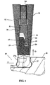
- Fig. 1 shows a tool according to an embodiment of the present invention in an assembled condition, partly in cross-section, in engagement with a work piece
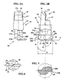
- Figs. 2A and 2B show side views of a cutting head according to an embodiment of the present invention, more in detail
- Fig. 3 shows a cross section according to the line III-III in Fig. 2
- Fig. 4 shows a top view of the cutting head.
- a tool according to the present invention shown in Fig. 1 comprises a cutting head 10, a retention means in form of a locking screw 11 and a shank 12.
- the tool comprises hook-shaped means 15, 19 provided on the cutting head and on the locking screw.
- the cutting head 10 is provided with cutting edges at the end 13 facing away from the shank 12.
- a preferred shape of the cutting head 10 is shown in detail in Figs. 2A - 4.
- the cutting head 10 is performed in hard material, preferably cemented carbide and comprises two major cutting edges 27.
- the number of major cutting edges may alternatively be one to six.
- Each major cutting edge 27 comprises a straight edge 27A and a convex curved, preferably part-circular edge 27B and is formed along the intersection line of a clearance surface 28 and a chip surface 29.
- the major cutting edges 27A are straight and lie in a common, imaginary cylinder, which is concentric with the axis CL of rotation of the cutting head and of the tool.
- the cutting edges 27A may be arranged in an imaginary truncated cone, the apex of which faces the shank 12.
- the diametrical distance between the major cutting edges is depicted by C, which normally is in the magnitude of 6 - 16 mm.
- Each major cutting edge 27B connects to an associated straight edge 27A via a corner having a radius R1, of maximum 1 mm.
- the major cutting edges 27B have a circular extension from the radius R1 to a plane P perpendicular to the center axis CL.
- Each major cutting edge 27B is defined by a radius R2, the center of which lies on a bisector B.
- the bisector is defined by an imaginary corner formed by the plane P and a line touching the radially outermost point of the major cutting edge 27B, said line being parallel to the rotational axis CL.
- a major portion of the major cutting edge 27B is provided above the bisector while a minor part thereof is provided below the bisector.
- the diametrical distance between the major cutting edges 27B is depicted by D and is some millimeters larger than the distance C.
- the convexly curved cutting edge 27B transforms into a minor cutting edge 30 in said plane P, with which said edge substantially coincides and extends radially inwards in.
- the radius R2 is less than one half of the diameter D, normally in the range of 1 - 6 mm.
- the minor cutting edge 30 forms an angle ⁇ with the rotational axis CL which is 90° or some degree less to improve the cutting properties during milling.
- Each chip surface 29 is substantially concavely formed and extends from the major cutting edge 27 radially inwards and from the minor cutting edge 30 in direction axially inwardly away from the free end 13 of the cutting head.
- the chip surface 29 forms an acute angle ⁇ , of 60° to 80° with the clearance surface 28A, 28B.
- the minor cutting edge 30 is formed at the intersection of the chip flute 29 and a clearance bevel 31 and its radial extension commences radially inside the imaginary cylinder.
- the minor cutting edge 30 connects to a cross-cutting edge 40 which intersects the rotational axis CL of the cutting head such that the tool shall be able to drill into the work piece during milling.
- the length of the cross-cutting edge 40 is 0.5 - 1.5 mm.
- Cut-out surfaces 41 are provided in line with the cross-cutting edge 40 in order to diminish the feed force during drilling.
- the clearance bevel 31 has a clearance angle ⁇ , of 10° to 20°, and is chosen preferably more acute than the clearance angle ⁇ of the major cutting edge to allow high feed during inwards ramping or drilling.
- the radial extension of the minor cutting edge 30 and the convex edge 27B can be described by an angle ⁇ , Fig. 2B, which is 120° - 140°. It should be noted that by the term “ramping” is here meant milling with feed directions in all angles relative to the rotational axis CL which is not the conventional drilling direction.
- first conical portion 14 which is provided with a first means for engagement 15, which in the shown embodiment comprises a first lip 16 as well as a first recess 17.
- first means for engagement 15 which in the shown embodiment comprises a first lip 16 as well as a first recess 17.
- the intermediate portion of the cutting head 10 is provided with a key grip 32, the application of which is explained below.
- the locking screw 11 which preferably is performed in steel, has a second conical portion 18 at the end facing towards the cutting head, which is provided with a second means for engagement 19, which is intended to cooperate with the first means for engagement 15.
- the second means for engagement 19 comprises a second lip 20 as well as a second recess 21. In active position the first lip 16 cooperates with the second recess 21 and the second lip 20 with the first recess 17.
- the locking screw 11 has an externally threaded, preferably cylindrical portion 22.
- An Allen key grip can be provided at the axially innermost end of the locking screw 11, whereby loosening or tightening of the locking screw 11 is made possible through the internal channel 24 of the shank 12. Normally however tightening or loosening of the locking screw is accomplished through the external key grip 32.
- the thread 26 may be arranged at an end of a releaseable sleeve, the other end of which then is provided with an external thread as well as a key grip.
- the shank 12 is provided with a conical seat 25 at the end facing towards the cutting head 10, which receives the first and second conical portions 14 and 18 of the cutting head 10 and the locking screw 11, respectively. Inside the conical seat 25 the shank 12 has a substantially cylindrical, internally threaded portion 26, which cooperates with the external threaded portion 22 of the locking screw 11.
- the threads 22 and 26 are performed as right-hand threads at tools for right-hand cutting and as left-hand threads at tools for left-hand cutting.
- the cone angle for the cutting head and seat should be less than 25°.
- the described embodiment relates to milling cutters, i.e. tools which rotate about their longitudinal center axes. Milling cutters with small cutting portions are expected to be the main area of application for the present invention.
- the milling tool according to the present invention thus can perform milling as conventional end mills of cemented carbide and yet cut material during a returning stroke towards the spindle. During the latter operation tension arises in the cutting head and therefore the chosen principal for retention is superior to other known solutions.
Landscapes
- Engineering & Computer Science (AREA)
- Mechanical Engineering (AREA)
- Milling Processes (AREA)
Claims (9)
- Fräswerkzeug für drehende, spanabhebende Bearbeitung mit Spanentfernung, wobei das Werkzeug einen Schneidkopf (10), ein Rückhaltemittel (11) und einen Schaft (12) aufweist, der Schneidkopf (10) mit mindestens einer Schneidkante (27, 30) versehen ist, die mit dem Schneidkopf einstückig ist, und der Schneidkopf und das Rückhaltemittel überlappende asymmetrische Mittel (15, 19) aufweisen für das Befestigen des Schneidkopfes an dem Schaft, wobei das Werkzeug eine Drehachse (CL) hat,
dadurch gekennzeichnet, daß der Schneidkopf eine bis sechs Hauptschneidkanten (27) aufweist, deren jede eine im wesentlichen gerade Kante (27A) und eine konvex gekrümmte, vorzugsweise teilkreisförmige Kante (27B) aufweist, wobei die konvexe Kante (27B) radial außerhalb der im wesentlichen geraden Kante (27A) vorgesehen ist. - Fräswerkzeug nach Anspruch 1, dadurch gekennzeichnet, daß die geraden Kanten (27A) in einem gemeinsamen, imaginären Zylinder mit einem ersten Durchmesser (D) liegen, der Zylinder konzentrisch zu der Drehachse (CL) des Werkzeuges und in einem imaginären, verjüngt zulaufenden Konus angeordnet ist, dessen Scheitel dem Schaft (12) zugewandt ist, und daß die konvexen Kanten (27B) mindesteins teilweise radial außerhalb des Zylinders oder des Konus vorgesehen sind.
- Fräswerkzeug nach Anspruch 1 oder 2, dadurch gekennzeichnet, daß die sich überlappenden, asymmetrischen Mittel aus hakenförmigen Mitteln (15, 19) bestehen und daß der Schneidkopf aus Sinterkarbid ausgeführt ist und daß Rückhaltemittel aus Stahl ausgeführt ist und daß das Rückhaltemittel (11) einen Abschnitt (22) mit Außengewinde hat und mit einer Ausnehmung (26) in dem Schaft (12) mit Innengewinde oder einer Hülse mit Innengewinde in einer aktiven Position des Werkzeuges in Eingriff kommen soll, wobei der Schneidkopf (10) mit einem konischen Abschnitt (14) versehen ist und der Schaft (12) mit einem konischen Sitz (25) versehen ist, welcher den konischen Abschnitt (14) in einer aktiven Position des Werkzeuges aufnimmt, wobei der Schneidkopf (10) lösbar mit dem Rückhaltemittel (11) über das hakenförmige Mittel (15, 19) verbunden ist.
- Fräswerkzeug nach einem der vorhergehenden Ansprüche, dadurch gekennzeichnet, daß der Schneidkopf zwei Hauptschneidkanten (27) hat und daß der diametrale Abstand zwischen den konvexen Kanten (27B) einige Millimeter größer ist als der Durchmesser (C) des Zylinders und daß die konvex gekrümmte Kante (27B) in einer Ebene (P), die zu der Drehachse senkrecht ist, in eine Nebenschneidkante (30) wechselt.
- Schneidkopf mit mindestens einer Schneidkante (27, 30), wobei der Schneidkopf in ein Werkzeug eintreten soll für spanabhebende Drehbearbeitung mit Spanentfernung, wobei das Werkzeug einen Schneidkopf (10), ein Rückhaltemittel (11) und einen Schaft (12) aufweist, der Schneidkopf (10) mit mindestens einer Schneidkante (27, 30) versehen ist, die mit dem Schneidkopf einstückig ist, und wobei der Schneidkopf und das Rückhaltemittel überlappende asymmetrische Mittel (15, 19) für die Befestigung des Schneidkopfes an dem Schaft aufweisen,
dadurch gekennzeichnet, daß der Schneidkopf eine bis sechs Hauptschneidkanten (27) aufweist, jede Hauptschneidkante (27) eine im wesentlichen gerade Kante (27A) und eine konvex gekrümmte, vorzugsweise teilkreisförmige Kante (27B) aufweist und die konvexe Kante (27B) radial außerhalb der im wesentlichen geraden Kante (27A) vorgesehen ist. - Schneidkopf nach Anspruch 15, dadurch gekennzeichnet, daß die geraden Kanten (27A) in einem gemeinsamen, imaginären Zylinder liegen, der einen ersten Durchmesser (D) hat, konzentrisch zu der Drehachse (CL) des Werkzeuges und in einem imaginären, verjüngt zulaufenden Konus angeordnet ist, dessen Scheitel dem Schaft (12) zugewandt ist, und daß die konvexen Kanten (27B) mindestens teilweise radial außerhalb des Zylinders oder des Konus vorgesehen sind.
- Schneidkopf nach Anspruch 5 oder 6, dadurch gekennzeichnet, daß der Schneidkopf aus Sinterkarbid ausgeführt ist und daß jede Hauptschneidkante (27A, 27B) längs der Schnittlinie zwischen einer Freifläche (28A, 28B) und einer Spanfläche (29) gebildet ist.
- Schneidkopf nach Anspruch 7, dadurch gekennzeichnet, daß das überlappende asymmetrische Mittel aus einem hakenförmigen Mittel (15) besteht.
- Schneidkopf nach Anspruch 8, dadurch gekennzeichnet, daß jede Hauptschneidkante (27) mit einer Nebenschneidkante (30) in Verbindung steht und der Schneidkopf zwei Hauptschneidkanten (27) hat und daß der diametrale Abstand zwischen den konvexen Kanten (27B) einige Millimeter größer ist als der Durchmesser (C) des Zylinders und daß die konvex gekrümmte Kante (27B) in einer Ebene (P), die senkrecht zu der Drehachse ist, in eine Nebenschneidkante (30) wechselt.
Applications Claiming Priority (3)
| Application Number | Priority Date | Filing Date | Title |
|---|---|---|---|
| SE9604456A SE507542C2 (sv) | 1996-12-04 | 1996-12-04 | Fräsverktyg samt skärdel till verktyget |
| SE9604456 | 1996-12-04 | ||
| PCT/SE1997/001847 WO1998024581A1 (en) | 1996-12-04 | 1997-11-05 | Milling tool |
Publications (2)
| Publication Number | Publication Date |
|---|---|
| EP0942799A1 EP0942799A1 (de) | 1999-09-22 |
| EP0942799B1 true EP0942799B1 (de) | 2002-04-03 |
Family
ID=20404849
Family Applications (1)
| Application Number | Title | Priority Date | Filing Date |
|---|---|---|---|
| EP97948051A Expired - Lifetime EP0942799B1 (de) | 1996-12-04 | 1997-11-05 | Fräser |
Country Status (10)
| Country | Link |
|---|---|
| US (1) | US5964555A (de) |
| EP (1) | EP0942799B1 (de) |
| JP (1) | JP2001505137A (de) |
| KR (1) | KR100484472B1 (de) |
| CN (1) | CN1087990C (de) |
| BR (1) | BR9713832A (de) |
| DE (1) | DE69711681T2 (de) |
| HK (1) | HK1023742A1 (de) |
| SE (1) | SE507542C2 (de) |
| WO (1) | WO1998024581A1 (de) |
Families Citing this family (33)
| Publication number | Priority date | Publication date | Assignee | Title |
|---|---|---|---|---|
| IL134226A (en) * | 2000-01-26 | 2003-12-10 | Iscar Ltd | Cutting tool assembly |
| SE526105C2 (sv) * | 2003-02-06 | 2005-07-05 | Seco Tools Ab | Fräs med tre konvext krökta skäreggar betning |
| DE20310713U1 (de) * | 2003-07-12 | 2003-09-18 | Fette Gmbh | Stirnfräser |
| SE528783C2 (sv) * | 2004-10-05 | 2007-02-13 | Seco Tools Ab | Verktyg där spets och hållare har radiella stödytor |
| JP4556676B2 (ja) * | 2005-01-14 | 2010-10-06 | トヨタ自動車株式会社 | プレス金型の抜き刃の二番逃がし部加工方法 |
| SE0501007L (sv) * | 2005-05-02 | 2006-10-03 | Sandvik Intellectual Property | Verktyg samt lösbar kropp för verktyg för spånavskiljande bearbetning med ås- och rillformade kopplingsmedel |
| US8637127B2 (en) | 2005-06-27 | 2014-01-28 | Kennametal Inc. | Composite article with coolant channels and tool fabrication method |
| US7687156B2 (en) | 2005-08-18 | 2010-03-30 | Tdy Industries, Inc. | Composite cutting inserts and methods of making the same |
| DE102005043841B4 (de) * | 2005-09-13 | 2009-01-22 | Franken GmbH + Co KG Fabrik für Präzisionswerkzeuge | Radiusfräser, insbesondere Kugel- oder Torusfräser, mit Querschneide und/oder Abflachung |
| US20070160430A1 (en) * | 2006-01-11 | 2007-07-12 | Yih Troun Enterprise Co., Ltd. | Milling cutter |
| RU2432445C2 (ru) | 2006-04-27 | 2011-10-27 | Ти Ди Уай Индастриз, Инк. | Модульное буровое долото с неподвижными режущими элементами, корпус данного модульного бурового долота и способы их изготовления |
| WO2008051588A2 (en) | 2006-10-25 | 2008-05-02 | Tdy Industries, Inc. | Articles having improved resistance to thermal cracking |
| US7846551B2 (en) | 2007-03-16 | 2010-12-07 | Tdy Industries, Inc. | Composite articles |
| FR2920327B1 (fr) * | 2007-08-30 | 2009-11-20 | Snecma | Fraise a rainurer pour usinage a grande avance et a faible profondeur de passe |
| US8790439B2 (en) | 2008-06-02 | 2014-07-29 | Kennametal Inc. | Composite sintered powder metal articles |
| CA2725318A1 (en) | 2008-06-02 | 2009-12-10 | Tdy Industries, Inc. | Cemented carbide-metallic alloy composites |
| US8025112B2 (en) | 2008-08-22 | 2011-09-27 | Tdy Industries, Inc. | Earth-boring bits and other parts including cemented carbide |
| US8322465B2 (en) | 2008-08-22 | 2012-12-04 | TDY Industries, LLC | Earth-boring bit parts including hybrid cemented carbides and methods of making the same |
| US8272816B2 (en) | 2009-05-12 | 2012-09-25 | TDY Industries, LLC | Composite cemented carbide rotary cutting tools and rotary cutting tool blanks |
| US8308096B2 (en) | 2009-07-14 | 2012-11-13 | TDY Industries, LLC | Reinforced roll and method of making same |
| US9643236B2 (en) | 2009-11-11 | 2017-05-09 | Landis Solutions Llc | Thread rolling die and method of making same |
| EP2516089B1 (de) * | 2009-12-22 | 2023-02-15 | Nuovo Pignone Tecnologie S.r.l. | Verfahren zum tauchfräsen eines werkstücks |
| EP2523627B1 (de) * | 2010-01-14 | 2017-07-19 | Osstemimplant Co., Ltd. | Bohrer für implantatchirurgie |
| CN101837486A (zh) * | 2010-05-31 | 2010-09-22 | 哈尔滨汽轮机厂有限责任公司 | 一种可换头式带有TiN复合涂层的硬质合金球头铣刀 |
| US8800848B2 (en) | 2011-08-31 | 2014-08-12 | Kennametal Inc. | Methods of forming wear resistant layers on metallic surfaces |
| CN102974877A (zh) * | 2011-09-07 | 2013-03-20 | 于君琴 | 铣刀 |
| US9016406B2 (en) | 2011-09-22 | 2015-04-28 | Kennametal Inc. | Cutting inserts for earth-boring bits |
| US10080579B2 (en) | 2015-03-25 | 2018-09-25 | Medtronic Ps Medical, Inc. | Pin drive rotary surgical cutting tools and powered handpieces |
| US10314610B2 (en) * | 2015-03-25 | 2019-06-11 | Medtronic Ps Medical, Inc. | Slanted drive axis rotary surgical cutting tools and powered handpieces |
| US9597737B2 (en) * | 2015-04-27 | 2017-03-21 | Iscar, Ltd. | Tool coupling arrangement for drills and reamers |
| ES1225597Y (es) * | 2019-02-05 | 2019-05-20 | Paragon Tools Sl | Herramienta de fresado para el asentamiento de un tornillo en una estructura dental |
| JP7114508B2 (ja) * | 2019-02-22 | 2022-08-08 | 三菱重工業株式会社 | エンドミルの製造方法及び切削加工方法 |
| US11731204B2 (en) * | 2020-10-19 | 2023-08-22 | Iscar, Ltd. | High-feed milling tool |
Family Cites Families (16)
| Publication number | Priority date | Publication date | Assignee | Title |
|---|---|---|---|---|
| US3708843A (en) * | 1971-11-05 | 1973-01-09 | Ingersoll Milling Machine Co | Holder for indexable cutting insert |
| US4168730A (en) * | 1978-01-03 | 1979-09-25 | Keller David A | Apparatus and methods for forming dovetail joints |
| JPS59214531A (ja) * | 1983-05-18 | 1984-12-04 | N T Tool Kk | 保持具 |
| JPS61270010A (ja) * | 1985-05-24 | 1986-11-29 | Toshiba Tungaloy Co Ltd | 穴あけ工具 |
| US4738130A (en) * | 1985-11-08 | 1988-04-19 | Kyoshin Kogyo Kabushiki Kaisha | Structure for mounting mandrels in tube expanding apparatus |
| US4759667A (en) * | 1985-11-08 | 1988-07-26 | American Telephone And Telegraph Company, At&T Technologies, Inc. | Twist drill for drilling printed circuit board laminates and having an drill point geometry |
| SE457935B (sv) * | 1987-07-08 | 1989-02-13 | Seco Tools Ab | Verktyg foer skaerande bearbetning samt skaerdel foer verktyget |
| US4948306A (en) * | 1987-08-08 | 1990-08-14 | Aldof Wurth GmbH & Co. KG | Drill |
| US4930945A (en) * | 1988-05-20 | 1990-06-05 | Mitsubishi Metal Corporation | Insert rotary cutter |
| GB8916263D0 (en) * | 1989-07-15 | 1989-08-31 | Technicut Limited | Router type cutter |
| US5116166A (en) * | 1990-11-06 | 1992-05-26 | Glenn Rinas | 45 degree miter undercutter bit |
| DE4114271A1 (de) * | 1991-05-02 | 1992-11-05 | Hilti Ag | Bohr- und meisselwerkzeug mit grundkoerper und schneidkoerper |
| SE507842C2 (sv) * | 1992-09-24 | 1998-07-20 | Sandvik Ab | Borr |
| EP0625395B1 (de) * | 1993-05-10 | 1995-04-19 | STELLRAM GmbH | Bohrwerkzeug für metallische Werkstoffe |
| SE508387C2 (sv) * | 1993-05-26 | 1998-10-05 | Sandvik Ab | Rundskär |
| IL106999A (en) * | 1993-09-13 | 1997-02-18 | Iscar Ltd | Cutting tool |
-
1996
- 1996-12-04 SE SE9604456A patent/SE507542C2/sv not_active IP Right Cessation
-
1997
- 1997-11-05 EP EP97948051A patent/EP0942799B1/de not_active Expired - Lifetime
- 1997-11-05 BR BR9713832-0A patent/BR9713832A/pt not_active IP Right Cessation
- 1997-11-05 CN CN97180276A patent/CN1087990C/zh not_active Expired - Lifetime
- 1997-11-05 JP JP52550398A patent/JP2001505137A/ja active Pending
- 1997-11-05 WO PCT/SE1997/001847 patent/WO1998024581A1/en active IP Right Grant
- 1997-11-05 KR KR10-1999-7004940A patent/KR100484472B1/ko not_active IP Right Cessation
- 1997-11-05 DE DE69711681T patent/DE69711681T2/de not_active Expired - Lifetime
- 1997-11-20 US US08/974,826 patent/US5964555A/en not_active Expired - Lifetime
-
2000
- 2000-05-19 HK HK00102995A patent/HK1023742A1/xx not_active IP Right Cessation
Also Published As
| Publication number | Publication date |
|---|---|
| SE507542C2 (sv) | 1998-06-22 |
| WO1998024581A1 (en) | 1998-06-11 |
| SE9604456D0 (sv) | 1996-12-04 |
| SE9604456L (sv) | 1998-06-05 |
| CN1087990C (zh) | 2002-07-24 |
| EP0942799A1 (de) | 1999-09-22 |
| KR100484472B1 (ko) | 2005-04-20 |
| HK1023742A1 (en) | 2000-09-22 |
| US5964555A (en) | 1999-10-12 |
| DE69711681T2 (de) | 2002-10-31 |
| CN1239450A (zh) | 1999-12-22 |
| KR20000057387A (ko) | 2000-09-15 |
| DE69711681D1 (de) | 2002-05-08 |
| JP2001505137A (ja) | 2001-04-17 |
| BR9713832A (pt) | 2000-02-29 |
Similar Documents
| Publication | Publication Date | Title |
|---|---|---|
| EP0942799B1 (de) | Fräser | |
| EP0942798B1 (de) | Spanabhebendes werkzeug | |
| US7695221B2 (en) | Solid drill bit for machine tools | |
| US4659264A (en) | Drill and indexable carbide insert therefor | |
| US6508612B1 (en) | Milling cutter capable of using inserts of various geometrical shapes | |
| EP1338364B1 (de) | Spiralbohrer | |
| EP0935508B1 (de) | Werkzeug für spanabnehmende bearbeitung | |
| US4606680A (en) | Reamer core drill with cutting bits | |
| EP1152858B1 (de) | Werkzeug und schneidkopf für spanabhebende bearbeitung | |
| US5855457A (en) | Disposable cutting tip clamp for a milling machine | |
| US4671710A (en) | Drill bit | |
| US7140815B2 (en) | Drill for making flat bottom hole | |
| EP3153260B1 (de) | Dreheinsatz und verfahren | |
| JPH0790409B2 (ja) | さら穴等工作回転カッタ | |
| EP3560638B1 (de) | Dreheinsatz | |
| US5259707A (en) | Spot drill with indexable replaceable insert | |
| US4470733A (en) | Multiple function cutting tool | |
| US5380133A (en) | Drill bit of the twist drill type | |
| CA2412515C (en) | Drilling tool | |
| US4188162A (en) | Indexable insert drill | |
| CA1328180C (en) | Drill with balanced inserts | |
| WO1996003242A1 (en) | Tool-bit holder | |
| US20010031181A1 (en) | Indexable drill and cutting inserts therefor | |
| CA1207566A (en) | Drill and indexable carbide insert therefor | |
| JPH10235510A (ja) | スローアウェイチップ |
Legal Events
| Date | Code | Title | Description |
|---|---|---|---|
| PUAI | Public reference made under article 153(3) epc to a published international application that has entered the european phase |
Free format text: ORIGINAL CODE: 0009012 |
|
| AK | Designated contracting states |
Kind code of ref document: A1 Designated state(s): DE FR GB IT SE |
|
| 17P | Request for examination filed |
Effective date: 19990527 |
|
| GRAG | Despatch of communication of intention to grant |
Free format text: ORIGINAL CODE: EPIDOS AGRA |
|
| GRAG | Despatch of communication of intention to grant |
Free format text: ORIGINAL CODE: EPIDOS AGRA |
|
| GRAH | Despatch of communication of intention to grant a patent |
Free format text: ORIGINAL CODE: EPIDOS IGRA |
|
| 17Q | First examination report despatched |
Effective date: 20010706 |
|
| GRAH | Despatch of communication of intention to grant a patent |
Free format text: ORIGINAL CODE: EPIDOS IGRA |
|
| REG | Reference to a national code |
Ref country code: GB Ref legal event code: IF02 |
|
| GRAA | (expected) grant |
Free format text: ORIGINAL CODE: 0009210 |
|
| AK | Designated contracting states |
Kind code of ref document: B1 Designated state(s): DE FR GB IT SE |
|
| REF | Corresponds to: |
Ref document number: 69711681 Country of ref document: DE Date of ref document: 20020508 |
|
| PG25 | Lapsed in a contracting state [announced via postgrant information from national office to epo] |
Ref country code: SE Free format text: LAPSE BECAUSE OF FAILURE TO SUBMIT A TRANSLATION OF THE DESCRIPTION OR TO PAY THE FEE WITHIN THE PRESCRIBED TIME-LIMIT Effective date: 20020703 |
|
| PLBE | No opposition filed within time limit |
Free format text: ORIGINAL CODE: 0009261 |
|
| STAA | Information on the status of an ep patent application or granted ep patent |
Free format text: STATUS: NO OPPOSITION FILED WITHIN TIME LIMIT |
|
| 26N | No opposition filed |
Effective date: 20030106 |
|
| REG | Reference to a national code |
Ref country code: FR Ref legal event code: PLFP Year of fee payment: 19 |
|
| REG | Reference to a national code |
Ref country code: FR Ref legal event code: PLFP Year of fee payment: 20 |
|
| PGFP | Annual fee paid to national office [announced via postgrant information from national office to epo] |
Ref country code: FR Payment date: 20161014 Year of fee payment: 20 Ref country code: GB Payment date: 20161102 Year of fee payment: 20 Ref country code: DE Payment date: 20161101 Year of fee payment: 20 |
|
| PGFP | Annual fee paid to national office [announced via postgrant information from national office to epo] |
Ref country code: IT Payment date: 20161122 Year of fee payment: 20 |
|
| REG | Reference to a national code |
Ref country code: DE Ref legal event code: R071 Ref document number: 69711681 Country of ref document: DE |
|
| REG | Reference to a national code |
Ref country code: GB Ref legal event code: PE20 Expiry date: 20171104 |
|
| PG25 | Lapsed in a contracting state [announced via postgrant information from national office to epo] |
Ref country code: GB Free format text: LAPSE BECAUSE OF EXPIRATION OF PROTECTION Effective date: 20171104 |