EP0942239B1 - Klimaanlage mit Eisspeicherung und Eisbehälter - Google Patents
Klimaanlage mit Eisspeicherung und Eisbehälter Download PDFInfo
- Publication number
- EP0942239B1 EP0942239B1 EP99103125A EP99103125A EP0942239B1 EP 0942239 B1 EP0942239 B1 EP 0942239B1 EP 99103125 A EP99103125 A EP 99103125A EP 99103125 A EP99103125 A EP 99103125A EP 0942239 B1 EP0942239 B1 EP 0942239B1
- Authority
- EP
- European Patent Office
- Prior art keywords
- heat transfer
- ice
- thermal storage
- storage tank
- plate
- Prior art date
- Legal status (The legal status is an assumption and is not a legal conclusion. Google has not performed a legal analysis and makes no representation as to the accuracy of the status listed.)
- Expired - Lifetime
Links
Images


Classifications
-
- F—MECHANICAL ENGINEERING; LIGHTING; HEATING; WEAPONS; BLASTING
- F24—HEATING; RANGES; VENTILATING
- F24F—AIR-CONDITIONING; AIR-HUMIDIFICATION; VENTILATION; USE OF AIR CURRENTS FOR SCREENING
- F24F5/00—Air-conditioning systems or apparatus not covered by F24F1/00 or F24F3/00, e.g. using solar heat or combined with household units such as an oven or water heater
- F24F5/0007—Air-conditioning systems or apparatus not covered by F24F1/00 or F24F3/00, e.g. using solar heat or combined with household units such as an oven or water heater cooling apparatus specially adapted for use in air-conditioning
- F24F5/0017—Air-conditioning systems or apparatus not covered by F24F1/00 or F24F3/00, e.g. using solar heat or combined with household units such as an oven or water heater cooling apparatus specially adapted for use in air-conditioning using cold storage bodies, e.g. ice
-
- F—MECHANICAL ENGINEERING; LIGHTING; HEATING; WEAPONS; BLASTING
- F28—HEAT EXCHANGE IN GENERAL
- F28D—HEAT-EXCHANGE APPARATUS, NOT PROVIDED FOR IN ANOTHER SUBCLASS, IN WHICH THE HEAT-EXCHANGE MEDIA DO NOT COME INTO DIRECT CONTACT
- F28D20/00—Heat storage plants or apparatus in general; Regenerative heat-exchange apparatus not covered by groups F28D17/00 or F28D19/00
- F28D20/02—Heat storage plants or apparatus in general; Regenerative heat-exchange apparatus not covered by groups F28D17/00 or F28D19/00 using latent heat
- F28D20/021—Heat storage plants or apparatus in general; Regenerative heat-exchange apparatus not covered by groups F28D17/00 or F28D19/00 using latent heat the latent heat storage material and the heat-exchanging means being enclosed in one container
-
- Y—GENERAL TAGGING OF NEW TECHNOLOGICAL DEVELOPMENTS; GENERAL TAGGING OF CROSS-SECTIONAL TECHNOLOGIES SPANNING OVER SEVERAL SECTIONS OF THE IPC; TECHNICAL SUBJECTS COVERED BY FORMER USPC CROSS-REFERENCE ART COLLECTIONS [XRACs] AND DIGESTS
- Y02—TECHNOLOGIES OR APPLICATIONS FOR MITIGATION OR ADAPTATION AGAINST CLIMATE CHANGE
- Y02E—REDUCTION OF GREENHOUSE GAS [GHG] EMISSIONS, RELATED TO ENERGY GENERATION, TRANSMISSION OR DISTRIBUTION
- Y02E60/00—Enabling technologies; Technologies with a potential or indirect contribution to GHG emissions mitigation
- Y02E60/14—Thermal energy storage
Definitions
- the present invention relates to an ice thermal storage tank according to the preamble of claim 1.
- Ice making methods in ice thermal storage type air-conditioners include two kinds of static method and dynamic method.
- static method icing forms and grows ice on a surface of a heat transfer unit or units provided in a thermal storage tank, so that there is caused a problem that heat transfer resistance increases with an increase in the thickness of ice and so ice making decreases in efficiency.
- a cooling medium of low temperature and low pressure is made to flow in the interior of a heat transfer unit or units provided on the bottom of an ice thermal storage tank to make ice, and then a cooling medium of high temperature and high pressure is made to flow to peel ice, which has grown, off the surface of the heat transfer unit so that ice pieces are permitted to come up to the upper portion of the thermal storage tank by their buoyancy and cold accumulates as ice in the thermal storage tank.
- An example of the dynamic method disclosed in Japanese Patent Laid-open Publication No. 42878/1996 is known.
- US-A-3 766 752 describes a refrigeration device comprising a refrigeration storage device containing a storage mass crystallizing at a temperature above 0°C and below 8°C.
- the storage mass is in good heat conducting communication with the evaporator of the refrigeration device. Water from the cold water circuit for an air conditioner is in thermal contact with the storage mass, such that heat may be transferred from the water to the storage mass.
- the storage mass forms a hydrate of an ionogenic material.
- the storage mass is arranged in thin-walled, vertically extending vessels consisting of thin flexible tubes and forming a unit with the channels of the evaporator, which channels are formed by a double walled sheet metal plate.
- the sheet metal plates are arranged side by side in a container and are relatively displaced in height that above and below the plates channels are formed, which taper when viewed at right angles to the sheet metal plates.
- US-A-2 460 623 describes the prior art of the generic kind referring to a tank for producing and storing ice, which reduces the temperature of the cooling fluid for an air conditioner.
- a cooling unit arranged in the tank comprises a plurality of spaced plates, which are made of two sheets of metal, between which refrigerant gas coils are arranged. The inlet end of each coil is connected to an upper header, while the outlet end is connected to a lower header.
- the plates are supported by links and springs in order to be able to move within a clearance under pressure of built-up ice.
- Between the plates of the cooling unit a plurality of heat diffusers is arranged such as to contact the plates by means of flanges. Each diffuser is provided with louvres to permit water circulation.
- the chamber sprayer heads are arranged, which can also be used to fill the chamber with water.
- the refrigerant gas is passing through the coils lower the temperature of the water to its freezing point through heat transfer through the plates.
- the diffusers act to diffuse the heat throughout the water that lies between the plates with the result that a solid mass of ice forms around the refrigerant unit. This ice is available to receive the water from the sprayer heads to reduce its temperature before being recirculated through a pipe to heat exchange units of the air conditioner.
- the present invention provides an ice thermal storage tank as described in claim 1 embodiments of which are subjects of subclaims 2 to 5.
- the heat transfer units of flat plate-type serving as an evaporator have substantially a size substantially corresponding to a height of a container of the ice thermal storage tank, and are disposed in layered manner in a thicknesswise direction in the ice thermal storage tank to eliminate gaps being not usable for ice making as unused portions in the ice thermal storage tank, so that the ice filling rate can be enhanced.
- the present invention also provides an ice thermal storage tank which contains therein water substantially to a height of a container thereof, and heat exchangers arranged in said ice thermal storage tank, the tank comprising a plurality of flat plate-type heat transfer units arranged in layered manner in a thicknesswise direction thereof in the ice thermal storage tank to permit icing to form and grow ice on surfaces of the plate-type heat transfer units.
- the heat transfer units serving as an evaporator at the time of ice making are of flat plate-type to be disposed in layered manner in a thicknesswise direction thereof, and ice is made to grow on the surfaces of the respective heat transfer units, so that ice formed is not increased in thickness, despite of ice making by the static method, more than required, and heat transfer resistance can be made small. Gaps being not usable for ice making as unused portions are eliminated, so that the ice filling rate can be enhanced.
- the present invention also provides an ice thermal storage tank which contains therein water substantially to a height of a container thereof, and heat exchangers arranged in the ice thermal storage tank, the tank comprising 20 to 60 plate-type heat transfer units having a thickness of 3 to 10 mm and provided in layered manner in a thicknesswise direction thereof at intervals of 10 to 50 mm in the ice thermal storage tank, and wherein icing forms and grows ice on surfaces of the plate-type heat transfer units.
- gaps being not usable for ice making as unused portions are reduced to enable enhancing the ice filling rate to the extent of 87% while being around 65% in the prior art.
- the present invention further provides an ice thermal storage tank which contains therein water substantially to a height of a container thereof, and a heat exchanger provided in the ice thermal storage tank and permitting a cooling medium to flow therein, the tank comprising a plurality of flat plate-type heat transfer units arranged in layered manner in a thicknesswise direction thereof in the ice thermal storage tank, and wherein at the time of ice making the cooling medium inflows at lower portions of the plate-type heat transfer units and outflows at upper portions of the units.
- the cooling medium inflows at the lower portions of the flat plate-type heat transfer units, so that ice making begins at the lower portions of the plate-type heat transfer units and during an ice making process, the water is not confined but escapes to go to the upper portions of the units. Therefore, portions being not usable for ice making are eliminated to enhance the ice filling rate, and damages against the plate-type heat transfer units can be avoided, which a part of water confined would then freeze and expand to cause.
- the present invention further provides an ice thermal storage tank which contains therein water substantially to a height of a container thereof, heat exchangers arranged in the ice thermal storage tank and comprising a plurality of flat plate-type heat transfer units arranged in layered manner in a thicknesswise direction thereof in the ice thermal storage tank, and header units connected to the plate-type heat transfer units and disposed outside the water.
- gaps between the plate-type heat transfer units and the header units to constitute unused portions are located outside the water, so that the ice filling rate can be enhanced.
- a plurality of rectifying members are disposed in the plate-type heat transfer units so that flow passages for a cooling medium branch and merge in repeated manner.
- mixing of the cooling medium is made better to enable uniformizing ice formed in thickness.
- a plurality of partitions having holes are disposed in the plate-type heat transfer units.
- contact portions between the inner surfaces of the plate-type heat transfer unit and the partitions are reduced. And it is possible to reduce thermal resistance from outside the plate-type heat transfer unit to the cooling medium flowing inside the plate-type heat transfer unit and to make the thermal resistance uniform.
- the plate-type heat transfer unit is constructed such that two plates are joined together to form flow passages therebetween.
- the number of parts can be reduced.
- the plate-type heat transfer unit is constructed such that two plates are joined together to form flow passages therebetween, and irregular rectifying members having different angles of inclination are disposed in the plate-type heat transfer unit.
- the number of parts is reduced, the cooling medium can be promoted to branch and flow together, and pressure loss in the plate-type heat transfer unit can be made small.
- the present invention further provides an ice thermal storage tank in which heat exchangers are installed, the heat exchangers comprising a plurality of flat plate-type heat transfer units which have a heightwise size extending from a bottom of said ice thermal storage tank to near a top of a container of the tank, and are arranged in layered manner in a thicknesswise direction.
- the present invention further provides an ice thermal storage tank in which heat exchangers are installed to permit a cooling medium to flow therein, the tank comprising a plurality of flat plate-type heat transfer units arranged therein in layered manner in a thicknesswise direction thereof, and in which the cooling medium inflows at lower portions of the plate-type heat transfer units and outflows at upper portions of the units.
- the heat transfer units of flat plate-type serving as an evaporator at the time of ice making have substantially a size extending to near a top of a container of the ice thermal storage tank, and are disposed in layered manner in a thicknesswise direction in the ice thermal storage tank to eliminate gaps being not usable for ice making as unused portions in the ice thermal storage tank, so that the ice thermal storage tank can be obtained in which the ice filling rate for the ice thermal storage tank can be enhanced.
- the heat transfer units are of flat plate-type to be disposed in layered manner in a thicknesswise direction, and ice is made to grow on the surfaces of the respective heat transfer units, so that an ice thermal storage tank can be obtained in which ice is not increased in thickness, despite of ice making by the static method, more than required, and the heat transfer resistance is made small.
- 20 to 60 plate-type heat transfer units having a thickness of 3 to 10 mm are provided in layered manner in a thicknesswise direction thereof at intervals of 10 to 50 mm in the ice thermal storage tank, and icing forms and grows ice on surfaces of the plate-type heat transfer units, so that an ice thermal storage tank can be obtained in which gaps being not usable for ice making as unused portions are reduced to enhance the ice filling rate to the extent of 87%.
- a plurality of flat plate-type heat transfer units are arranged in layered manner in a thicknesswise direction thereof in the ice thermal storage tank, and the cooling medium inflows at the lower portions of the plate-type heat transfer units and outflows at the upper portions of the units, so that ice making begins at the lower portions of the plate-type heat transfer units and proceeds toward the upper portions of the units in a state that water is not confined. Therefore, an ice thermal storage tank can be obtained for avoiding damages against the plate-type heat transfer units, which a part of water confined would then freeze and expand to cause.
- a plurality of flat plate-type heat transfer units are arranged in layered manner in a thicknesswise direction thereof in the ice thermal storage tank, header units are disposed outside the water, and gaps between the plate-type heat transfer units and the header units are located outside the water, so that an ice thermal storage tank can be obtained in which the ice filling rate is enhanced.
- a plurality of flat plate-type heat transfer units having a heightwise size extending from a bottom of the ice thermal storage tank to near a top of a container of the tank are arranged in layered manner in a thicknesswise direction, so that an ice thermal storage tank can be obtained in which gaps being not usable for ice making as unused portions are eliminated to enhance the ice filling rate.
- a plurality of flat plate-type heat transfer units are arranged in layered manner in a thicknesswise direction thereof, the cooling medium inflows at the lower portions of the plate-type heat transfer units and outflows at the upper portions of the units, ice making proceeds toward the upper portions of the plate-type heat transfer units in a state that water is not confined, so that an ice thermal storage tank can be obtained which is free from damages against the plate-type heat transfer units, which a part of water confined would then freeze and expand to cause.
- an ice thermal storage type air-conditioner comprises an outdoor unit 7, in which a compressor 6, an outdoor heat exchanger 4 and the like are put together, a thermal storage unit 8, in which an ice thermal storage tank 1, branched piping and the like are put together, and an indoor unit 9 including an indoor heat exchanger 5.
- the refrigeration cycle is executed mainly at night by the use of midnight electric power so as to store in the ice thermal storage tank 1 cold in the form of ice, and the cold is utilized for air-conditioning in daytime.
- a heat transfer pipe (heat transfer unit) 3 in the ice thermal storage tank 1 is made to serve as an evaporator in the refrigeration cycle so as to make ice on its surface to store cold.
- a cooling medium of high temperature and high pressure from the compressor 6 passes through the outdoor heat exchanger 4, which acts as a condenser, an expansion valve 24a, which is controlled in opening degree, the heat transfer pipe 3, which acts as an evaporator in the thermal storage tank 1, and a valve 25, and then returns to the compressor 6.
- the expansion valve 24b is fully closed.
- the heat exchanger in the thermal storage tank 1 is used as a part of the condenser in the refrigeration cycle, so that a cooling medium of high temperature and high pressure is made to flow in the heat exchanger and ice 2 is thawed from the ice making surface of the heat transfer pipe 3 to provide cold.
- the refrigeration cycle is executed in order of the compressor 6, the outdoor heat exchanger 4, which acts as condensers, the thermal storage tank 1, the expansion valve 24a, and the indoor heat exchanger 5, which acts as an evaporator (the valve 25 is fully closed).
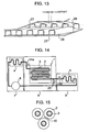
- the heat transfer pipe 3 used for ice making in the ice thermal storage tank 1 comprises a copper pipe (having an outside diameter of about 7 to 9 mm) having a circular cross-section and bent in zigzag manner.
- ice formed on the surface of the copper pipe is tubular in shape to have a substantially circular cross-section as shown in Fig. 15, and there are created unused potions 10 between ice bodies 2 formed on adjacent heat transfer pipe (copper pipe) 3 portions in vertical and lateral directions.
- an ice filling rate (a ratio of an ice volume to a total water volume filled) is at most around 65%.
- ice 2 having a thickness of 60 to 70 mm must be formed on the surface of the heat transfer pipe 3 and the thermal resistance over an extent from the heat transfer surface to the formed surface of ice increases with the formation of ice 2, so that it takes a long time until ice making is completed.
- ice bodies 2 having grown on adjacent heat transfer pipe 3 portions confine water in the unused portion 10 to cut off the same from escape, resulting in a possibility that the water in the unused portion 10 then freezes and expands to cause breakage on the heat transfer pipe 3.
- the cylindrical-shape ice thermal storage tank 1a is constructed such that a plurality of vertical plate-type heat transfer units 14 are packed vertically in the tank to be layered in thicknesswise direction thereof to be submerged in the tank. With the arrangement, formation of unused portions 10 between the adjacent heat transfer units 14 and those gaps around a cooling medium inlet side header 11 and an outlet side header 12, which are unusable for ice making, can be avoided to improve the ice filling rate.
- a heat transfer unit in the form of a copper pipe (pipe diameter of ⁇ 8, and total length of 208 m) having a circular cross-section provides an amount of ice of 0.988 m 3 attached thereto with an ice filling rate of about 65%.
- the ice filling rate can be increased to 87%.
- plate-type heat transfer units 14 can be arranged with less gaps therebetween to further increase the ice filling rate.
- the cooling medium inlet side header 11 and the cooling medium outlet side header 12 are disposed above the plate-type heat transfer units 14, so that the plate-type heat transfer units 14 suffice to be inserted from above the cylindrical thermal storage tank 1a to enable improving a manufacturing quality.
- inlet side header 11 is not submerged in the water, it is possible to prevent ice from being unevenly formed on the inlet side header 11 to cause damage to the heat transfer pipe. Further, in the case of a heat transfer pipe having a circular cross-section, ice formed around the pipe will also have a circular cross-section to provide an increased rate in thermal resistance with the progress of thermal storage.
- non-azeotrope cooling medium typified by HFC407C
- the non-azeotrope cooling medium having a feature that its evaporation temperature rises as the evaporation proceeds.
- the cooling medium inflows at the lower portions of the plate-type heat transfer units 14 to go upward, the more an amount of ice formed at the lower portions of the plate-type heat transfer units 14, the less the amount at the upper portions of the units because the evaporation temperature of the cooling medium rises as the evaporation proceeds.
- water between the plate-type heat transfer units 14 is not confined but escapes to go to the upper portions of the units, so that damage, which water would be confined to cause to the heat transfer units, is avoided.
- a large number of plate-type heat transfer units 14 having a rectangular-shaped cross-section are packed vertically in a heightwise direction of the cylindrical thermal storage tank 1a to be submerged in the water in the tank.
- the width of every plate-type heat transfer units 14 is not conformed to the dimension at respective mount locations but two kinds of plate-type heat transfer units 14a and 14b having basic widths of a and b, respectively, are used in combination to fill the objective thermal storage tank 1a highly densely.
- the plate-type heat transfer units 14 when used in combination with a square-shaped thermal storage tank 1b as shown in Fig. 3, they can be packed in the tank with higher density than that with the case where a cylindrical thermal storage tank 1a is used, and so the ice filling rate is further enhanced. Moreover, since headers center on the upper portion of the tank, it is possible to enhance an existing thermal storage tank in ice filling rate by removing a group of conventional zigzag shaped heat transfer pipes from the existing thermal storage tank and instead charging the plate-type heat transfer units 14 in the tank from above.
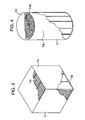
- a plate-type heat transfer unit 14 shown in Fig. 5 is constructed in the manner that a large number of disk-shaped rectifying members 15a are packed in a casing 19. Since both sides of the disk-shaped rectifying members 15a are chamfered at edges thereof, the chamfered portions of the rectifying members can ensure flow passages for the cooling medium 13 even if the rectifying members 15a are packed to contact with one another. Accordingly, mixing of the cooling medium 13 is made better to enabling uniformizing the thickness of ice formed. Also, productivity can be improved since the casing 19 of the plate-type heat transfer unit 14 and the rectifying members 15a are required not to be integral with each other or not to be fixed while being provided with gaps for flow passages 23 for the cooling medium.
- a large number of cord-shaped rectifying members 15b are packed in the casing 19 of a plate-type heat transfer unit 14, and are varied in a packing rate to ensure flow passages 23 for the cooling medium according to the size of the casing 19. Further, varying the packing rate of the cord-shaped rectifying members 15b also in a heightwise direction of the plate-type heat transfer unit 14 can easily vary the sizes of the flow passages 23 for the cooling medium in accordance with the composition of the vapor-liquid two-phase flow.
- a large number of rhomb-shaped rectifying members 15 are provided inside both heat transfer surfaces of a plate-type heat transfer unit 14 to be shifted in mount positions so as not to overlap with one another.
- the cooling medium 13 is made to uniformly mix only in heightwise and widthwise directions of the plate-type heat transfer unit 14 in the arrangement shown in Fig. 5, uniform mixing of the cooling medium 13 can be made in the arrangement shown in Fig. 7 to uniformly mix in a thickness direction of the plate-type heat transfer unit 14 as well as in heightwise and widthwise directions of the plate-type heat transfer unit, so that it is possible to promote uniformity in vapor-liquid two-phase flow cooling medium.
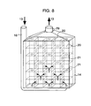
- a large number of partitions 20 each formed with holes 21 are provided in the casing 19 of the plate-type heat transfer unit 14 in heightwise and widthwise directions of the unit to constitute rectifying members 15 for forming flow passages 23 for the cooling medium.
- contact portions between the casing 19 of the plate-type heat transfer unit 14 and the rectifying members 15 can be reduced as compared with those shown in Fig. 5, it is possible to reduce thermal resistance from the water outside the plate-type heat transfer unit 14 to the cooling medium 13 flowing inside the plate-type heat transfer unit 14, and to make the thermal resistance for the heat transfer surface more uniform.
- cooling medium inlet pipes 16 for introducing a cooling medium 13 into a plate-type heat transfer unit 14 are flattened in one direction (thicknesswise direction of the casing in the drawing) to make gaps between the pipes and the casing small, whereby the pipes serve as partitions 20 which function as rectifying members 15. Further, constricted portions 22 are provided partially on the respective cooling medium pipes 16 to enable serving as flow passages 23 for the cooling medium. Therefore, a process of joining the cooling medium pipes 16 to the outside of the plate-type heat transfer unit 14 can be omitted, and also substitution of the flattened cooling medium pipes 16 for parts of the partitions 20 can reduce the number of parts as compared with the arrangement shown in Fig. 8.
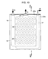
- plates 27a and 27b for formation of a heat transfer unit are joined together to form a cooling medium pipe 16 and cooling medium flow passages 23.
- One of the plates 27a is provided with a plurality of projections 26 which are extruded toward surfaces being joined. Therefore, the number of constituent parts can be considerably reduced, and a joining work, cutting work or the like for securing of the rectifying members, required in the arrangement shown in Fig. 7, can be omitted.
- the plate thickness of the projections 26 can be made equal to that of the remaining portions of the plates, so that thermal resistance in the vicinities of the projections 26 can be prevented from increasing.
- an oil return pipe 17, which permits a lubricant 18 of a compressor 6, mixed in the cooling medium 13, to return to the compressor 6 again, is provided in the lower portion of the plate-type heat transfer unit 14 as desired. Since all of the cooling medium inlet pipe 16, plate-type heat transfer unit 14, cooling medium outlet pipe 28 and oil return pipe 17 are formed integrally by joining together, the plate-type heat transfer unit 14 and cooling medium inlet pipe 16 can dispense with joined portions or the like, of which corrosion can be prevented to improve the reliability.
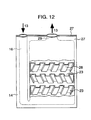
- plates 27 for formation of a heat transfer unit are joined together to form a cooling medium inlet pipe 16 integrally with the plates 27, in the same manner shown in Fig. 10.
- irregular-shaped rectifying members 28 having different angles of inclination are fixed inside of the plates 27 to be arranged alternately in the flow direction of the cooling medium 13.
- the cooling medium 13 flows through tubular flow passages 23 (having rectangular cross-sections) for the cooling medium, the passages being defined by the irregularities of the rectifying members 28 and the inner walls of the plates 27.
- the irregular-shaped rectifying members 28 arranged successively alternately in the flow direction of the cooling medium 13 are disposed to be offset relative to one another as shown in Fig. 13. Accordingly, the cooling medium 13 can be made to branch and flow together when flowing from the irregular-shaped rectifying member 28 to the downstream rectifying member 28.
- the irregular-shaped rectifying members 28 makes it possible to promote branching and flowing-together of the cooling medium 13. Accordingly, the cooling medium 13 flowing along the irregular-shaped rectifying members 28 is rectified only in one direction at the respective stages, so that pressure loss between the plates 27 can be held down to a lower level than that in the arrangement shown in Figs. 5 and 7.
- the irregular-shaped rectifying member 28 can be formed integrally for the respective stages to reduce the number of parts (or processes).
Landscapes
- Engineering & Computer Science (AREA)
- Mechanical Engineering (AREA)
- General Engineering & Computer Science (AREA)
- Life Sciences & Earth Sciences (AREA)
- Sustainable Development (AREA)
- Chemical & Material Sciences (AREA)
- Combustion & Propulsion (AREA)
- Physics & Mathematics (AREA)
- Thermal Sciences (AREA)
- Other Air-Conditioning Systems (AREA)
- Heat-Exchange Devices With Radiators And Conduit Assemblies (AREA)
Claims (5)
- Eis-Thermospeicherbehälter (1, 1a), in welchem eine Vielzahl von flachen Wärmeübertragungseinheiten (14, 14a, 14b, 14c) in Plattenbauweise in ihrer Dickenrichtung geschichtet angeordnet und in in dem Behälter (1, 1a) vorhandenem Wasser eingetaucht sind, dadurch gekennzeichnet, dass die Wärmeübertragungseinheiten (14, 14a, 14b, 14c) an ihren unteren Abschnitten Kühlmediumzuflüsse und an ihren oberen Abschnitten Abflüsse aufweisen, wobei auf den Oberflächen der Einheiten (14, 14a, 14b, 14c) Eis gebildet wird.
- Eis-Thermospeicherbehälter (1, 1a) nach Anspruch 1, dadurch gekennzeichnet, dass die flachen Wärmeübertragungseinheiten (14, 14a, 14b, 14c) in Plattenbauweise in ihrer Dickenrichtung in Abständen von 10 bis 50 mm geschichtet angeordnet sind und jede der Einheiten (14, 14a, 14b, 14c) einen rechteckigen Querschnitt und eine Höhe hat, die sich vom Boden des Behälters (1, 1a) bis in die Nähe seines oberen Endes erstreckt.
- Eis-Thermospeicherbehälter (1, 1a) nach Anspruch 1 oder 2, dadurch gekennzeichnet, dass eine Vielzahl von Trennwänden (20) mit Löchern (21) in jeder der Wärmeübertragungseinheiten (14, 14a, 14b, 14c) in Plattenbauweise angeordnet ist.
- Eis-Thermospeicherbehälter (1, 1a) nach einem der vorhergehenden Ansprüche, dadurch gekennzeichnet, dass die Wärmeübertragungseinheiten (14, 14a, 14b, 14c) in Plattenbauweise so gebaut sind, dass zwei Platten (27) zur Bildung von Strömungskanälen (23) dazwischen verbunden sind und dass eine Vielzahl von unregelmäßigen Gleichrichtelementen (28) mit unterschiedlichen Neigungswinkeln in jeder der Wärmeübertragungseinheiten (14, 14a, 14b, 14c) in Plattenbauweise angeordnet sind.
- Eis-Thermospeicherbehälter (1, 1a) nach einem der vorhergehenden Ansprüche, dadurch gekennzeichnet, dass die Wärmeübertragungseinheiten (14a, 14b) in Plattenbauweise Grundbreiten (a, b) haben und in Kombination verwendet werden, um den Behälter (1a) mit hoher Dichte zu füllen.
Applications Claiming Priority (2)
| Application Number | Priority Date | Filing Date | Title |
|---|---|---|---|
| JP06252298A JP3353692B2 (ja) | 1998-03-13 | 1998-03-13 | 氷蓄熱式空気調和装置及び氷蓄熱槽 |
| JP6252298 | 1998-03-13 |
Publications (3)
| Publication Number | Publication Date |
|---|---|
| EP0942239A2 EP0942239A2 (de) | 1999-09-15 |
| EP0942239A3 EP0942239A3 (de) | 2002-06-05 |
| EP0942239B1 true EP0942239B1 (de) | 2005-11-02 |
Family
ID=13202613
Family Applications (1)
| Application Number | Title | Priority Date | Filing Date |
|---|---|---|---|
| EP99103125A Expired - Lifetime EP0942239B1 (de) | 1998-03-13 | 1999-02-17 | Klimaanlage mit Eisspeicherung und Eisbehälter |
Country Status (6)
| Country | Link |
|---|---|
| US (1) | US6101837A (de) |
| EP (1) | EP0942239B1 (de) |
| JP (1) | JP3353692B2 (de) |
| CN (1) | CN1174193C (de) |
| DE (1) | DE69928036T2 (de) |
| ES (1) | ES2248934T3 (de) |
Cited By (2)
| Publication number | Priority date | Publication date | Assignee | Title |
|---|---|---|---|---|
| DE102007048416A1 (de) | 2007-10-09 | 2009-04-16 | Ingenieurtechnik-Vritex Gmbh | Eisspeicher mit Wärmeaustauscheinheiten in Plattenbauweise |
| WO2014064667A1 (en) * | 2012-10-26 | 2014-05-01 | CoolFactor, LLC | Self-contained evaporative air conditioner system |
Families Citing this family (12)
| Publication number | Priority date | Publication date | Assignee | Title |
|---|---|---|---|---|
| SE509081C2 (sv) * | 1997-02-14 | 1998-11-30 | Aga Ab | Sätt och anordning för kylning av en produkt med utnyttjande av kondenserad gas |
| US6247522B1 (en) * | 1998-11-04 | 2001-06-19 | Baltimore Aircoil Company, Inc. | Heat exchange members for thermal storage apparatus |
| US20030131623A1 (en) * | 2001-09-05 | 2003-07-17 | Suppes Galen J. | Heat pump using phase change materials |
| US7134483B2 (en) * | 2003-09-26 | 2006-11-14 | Flair Corporation | Refrigeration-type dryer apparatus and method |
| US20050172660A1 (en) * | 2004-02-05 | 2005-08-11 | Anderson R. D. | Thermal energy storage device and method |
| US20110278307A1 (en) * | 2006-10-23 | 2011-11-17 | Ralph Muscatell | Water tank for use with a solar air conditioning system |
| US7671567B2 (en) * | 2007-06-15 | 2010-03-02 | Tesla Motors, Inc. | Multi-mode charging system for an electric vehicle |
| US20110100583A1 (en) * | 2009-10-29 | 2011-05-05 | Freund Sebastian W | Reinforced thermal energy storage pressure vessel for an adiabatic compressed air energy storage system |
| GB2497139B (en) * | 2011-12-02 | 2015-11-11 | Vkr Holding As | Phase change material pack |
| CN112178763B (zh) * | 2019-07-02 | 2023-06-16 | 青岛海尔空调电子有限公司 | 空气调节装置 |
| CN112747398A (zh) * | 2021-01-30 | 2021-05-04 | 中建八局第一建设有限公司 | 一种大型水蓄冷罐 |
| CN114992694A (zh) * | 2022-05-18 | 2022-09-02 | 叶卫东 | 水或冰储存罐 |
Family Cites Families (19)
| Publication number | Priority date | Publication date | Assignee | Title |
|---|---|---|---|---|
| US2460623A (en) * | 1944-10-24 | 1949-02-01 | Reconstruction Finance Corp | Liquid cooler for air-conditioning systems |
| US2538016A (en) * | 1948-09-18 | 1951-01-16 | Dole Refrigerating Co | Liquid cooler |
| US3648665A (en) * | 1969-07-11 | 1972-03-14 | Dunlop Holdings Ltd | Perforated structures |
| US3653221A (en) * | 1970-07-17 | 1972-04-04 | Frank M Angus | Latent storage air-conditioning system |
| CH544270A (de) * | 1971-05-21 | 1973-11-15 | Thermo Bauelement Ag | Kälteanlage mit einer schmelzbaren Speichermasse |
| US4116651A (en) * | 1976-08-23 | 1978-09-26 | Rickert Glenn E | Heat sink temperature stabilized evaporator coil |
| IN161820B (de) * | 1983-08-26 | 1988-02-06 | Gilbertson Thomas A | |
| JPS60149891A (ja) * | 1984-01-13 | 1985-08-07 | Taisei Corp | 蓄熱装置 |
| US4831831A (en) * | 1988-02-16 | 1989-05-23 | Baltimore Aircoil Company, Inc. | Thermal storage unit with coil extension during melt |
| US4827735A (en) * | 1988-04-07 | 1989-05-09 | Off-Peak Devices, Inc. | Off peak storage device |
| US5054298A (en) * | 1990-10-26 | 1991-10-08 | Calmac Manufacturing Corporation | Ice-cap prevention barrier for an ice bank |
| US5239839A (en) * | 1991-06-17 | 1993-08-31 | James Timothy W | Thermal energy storage apparatus enabling use of aqueous or corrosive thermal storage media |
| JPH05223417A (ja) * | 1992-02-13 | 1993-08-31 | Misawa Homes Co Ltd | 氷蓄熱槽 |
| JP3197053B2 (ja) * | 1992-04-10 | 2001-08-13 | サンデン株式会社 | 冷却貯蔵庫 |
| US5272887A (en) * | 1992-08-11 | 1993-12-28 | Zendzian Sr Peter R | Portable refrigeration hold-over pack |
| JPH0719684A (ja) * | 1993-06-30 | 1995-01-20 | Showa Alum Corp | 製氷板 |
| US5944089A (en) * | 1994-05-26 | 1999-08-31 | Roland; Russel Anthony | Thermal storage systems for buildings |
| US5524453A (en) * | 1994-08-01 | 1996-06-11 | James; Timothy W. | Thermal energy storage apparatus for chilled water air-conditioning systems |
| US5649431A (en) * | 1994-11-15 | 1997-07-22 | Tdindustries, Inc. | Thermal storage cooling system |
-
1998
- 1998-03-13 JP JP06252298A patent/JP3353692B2/ja not_active Expired - Fee Related
-
1999
- 1999-02-17 DE DE69928036T patent/DE69928036T2/de not_active Expired - Lifetime
- 1999-02-17 ES ES99103125T patent/ES2248934T3/es not_active Expired - Lifetime
- 1999-02-17 EP EP99103125A patent/EP0942239B1/de not_active Expired - Lifetime
- 1999-03-09 US US09/264,871 patent/US6101837A/en not_active Expired - Fee Related
- 1999-03-12 CN CNB991036832A patent/CN1174193C/zh not_active Expired - Fee Related
Cited By (3)
| Publication number | Priority date | Publication date | Assignee | Title |
|---|---|---|---|---|
| DE102007048416A1 (de) | 2007-10-09 | 2009-04-16 | Ingenieurtechnik-Vritex Gmbh | Eisspeicher mit Wärmeaustauscheinheiten in Plattenbauweise |
| DE102007048416B4 (de) * | 2007-10-09 | 2009-08-06 | Ingenieurtechnik-Vritex Gmbh | Eisspeicher mit Wärmeaustauscheinheiten in Plattenbauweise |
| WO2014064667A1 (en) * | 2012-10-26 | 2014-05-01 | CoolFactor, LLC | Self-contained evaporative air conditioner system |
Also Published As
| Publication number | Publication date |
|---|---|
| EP0942239A3 (de) | 2002-06-05 |
| US6101837A (en) | 2000-08-15 |
| ES2248934T3 (es) | 2006-03-16 |
| DE69928036T2 (de) | 2006-07-13 |
| EP0942239A2 (de) | 1999-09-15 |
| JP3353692B2 (ja) | 2002-12-03 |
| JPH11257692A (ja) | 1999-09-21 |
| CN1174193C (zh) | 2004-11-03 |
| CN1229898A (zh) | 1999-09-29 |
| DE69928036D1 (de) | 2005-12-08 |
Similar Documents
| Publication | Publication Date | Title |
|---|---|---|
| US6253567B1 (en) | Ice thermal storage type air conditioner and ice thermal storage tank | |
| EP0942239B1 (de) | Klimaanlage mit Eisspeicherung und Eisbehälter | |
| KR101137031B1 (ko) | 축냉 열교환기 | |
| US6101821A (en) | Ice thermal storage coil systems and methods | |
| US6178770B1 (en) | Ice-on-coil thermal storage apparatus and method | |
| US6247522B1 (en) | Heat exchange members for thermal storage apparatus | |
| JP3340785B2 (ja) | 冷凍システム又はヒートポンプシステムに使用するための蒸発器又は蒸発器兼凝縮器及びその製造方法並びに蒸発器の少なくとも一部分として用いるための熱交換器 | |
| KR100225276B1 (ko) | 열저장장치의 운전방법 및 그에 사용되는 장치 | |
| US5944089A (en) | Thermal storage systems for buildings | |
| US10371422B2 (en) | Condenser with tube support structure | |
| US20040188076A1 (en) | Heat exchanger | |
| JP2016528473A (ja) | 熱交換器 | |
| WO2017073715A1 (ja) | アルミニウム製押出扁平多穴管及び熱交換器 | |
| CN108709445B (zh) | 保冷热交换器 | |
| EP0073584A2 (de) | Verdampfer für Kühlschränke | |
| JPH0762596B2 (ja) | 空気調和機用アルミニウム製凝縮器 | |
| JPH11264630A (ja) | 空気調和機 | |
| JPH0620036Y2 (ja) | 蓄熱システム | |
| JP2005300073A (ja) | 蒸発器 | |
| JP3837613B2 (ja) | 製氷用熱交換器 | |
| JP3790207B2 (ja) | 空気調和装置 | |
| JP3814570B2 (ja) | 空気調和装置 | |
| KR20240044900A (ko) | 열교환기 | |
| JPH06137616A (ja) | 氷蓄熱槽用の熱交換コイル | |
| JPH08240364A (ja) | 過冷却水製造装置 |
Legal Events
| Date | Code | Title | Description |
|---|---|---|---|
| PUAI | Public reference made under article 153(3) epc to a published international application that has entered the european phase |
Free format text: ORIGINAL CODE: 0009012 |
|
| 17P | Request for examination filed |
Effective date: 19990217 |
|
| AK | Designated contracting states |
Kind code of ref document: A2 Designated state(s): AT BE CH CY DE DK ES FI FR GB GR IE IT LI LU MC NL PT SE |
|
| AX | Request for extension of the european patent |
Free format text: AL;LT;LV;MK;RO;SI |
|
| PUAL | Search report despatched |
Free format text: ORIGINAL CODE: 0009013 |
|
| AK | Designated contracting states |
Kind code of ref document: A3 Designated state(s): AT BE CH CY DE DK ES FI FR GB GR IE IT LI LU MC NL PT SE |
|
| AX | Request for extension of the european patent |
Free format text: AL;LT;LV;MK;RO;SI |
|
| AKX | Designation fees paid |
Designated state(s): DE ES GB |
|
| 17Q | First examination report despatched |
Effective date: 20040906 |
|
| GRAP | Despatch of communication of intention to grant a patent |
Free format text: ORIGINAL CODE: EPIDOSNIGR1 |
|
| GRAS | Grant fee paid |
Free format text: ORIGINAL CODE: EPIDOSNIGR3 |
|
| GRAA | (expected) grant |
Free format text: ORIGINAL CODE: 0009210 |
|
| AK | Designated contracting states |
Kind code of ref document: B1 Designated state(s): DE ES GB |
|
| REG | Reference to a national code |
Ref country code: GB Ref legal event code: FG4D |
|
| REF | Corresponds to: |
Ref document number: 69928036 Country of ref document: DE Date of ref document: 20051208 Kind code of ref document: P |
|
| REG | Reference to a national code |
Ref country code: ES Ref legal event code: FG2A Ref document number: 2248934 Country of ref document: ES Kind code of ref document: T3 |
|
| PLBE | No opposition filed within time limit |
Free format text: ORIGINAL CODE: 0009261 |
|
| STAA | Information on the status of an ep patent application or granted ep patent |
Free format text: STATUS: NO OPPOSITION FILED WITHIN TIME LIMIT |
|
| 26N | No opposition filed |
Effective date: 20060803 |
|
| PGFP | Annual fee paid to national office [announced via postgrant information from national office to epo] |
Ref country code: DE Payment date: 20110208 Year of fee payment: 13 |
|
| PGFP | Annual fee paid to national office [announced via postgrant information from national office to epo] |
Ref country code: GB Payment date: 20110216 Year of fee payment: 13 Ref country code: ES Payment date: 20110218 Year of fee payment: 13 |
|
| GBPC | Gb: european patent ceased through non-payment of renewal fee |
Effective date: 20120217 |
|
| REG | Reference to a national code |
Ref country code: DE Ref legal event code: R119 Ref document number: 69928036 Country of ref document: DE Effective date: 20120901 |
|
| PG25 | Lapsed in a contracting state [announced via postgrant information from national office to epo] |
Ref country code: GB Free format text: LAPSE BECAUSE OF NON-PAYMENT OF DUE FEES Effective date: 20120217 |
|
| PG25 | Lapsed in a contracting state [announced via postgrant information from national office to epo] |
Ref country code: DE Free format text: LAPSE BECAUSE OF NON-PAYMENT OF DUE FEES Effective date: 20120901 |
|
| REG | Reference to a national code |
Ref country code: ES Ref legal event code: FD2A Effective date: 20130708 |
|
| PG25 | Lapsed in a contracting state [announced via postgrant information from national office to epo] |
Ref country code: ES Free format text: LAPSE BECAUSE OF NON-PAYMENT OF DUE FEES Effective date: 20120218 |