EP0941928B1 - Procédé et machine de formation de sachets avec fermeture à profilés transversaux - Google Patents
Procédé et machine de formation de sachets avec fermeture à profilés transversaux Download PDFInfo
- Publication number
- EP0941928B1 EP0941928B1 EP99400548A EP99400548A EP0941928B1 EP 0941928 B1 EP0941928 B1 EP 0941928B1 EP 99400548 A EP99400548 A EP 99400548A EP 99400548 A EP99400548 A EP 99400548A EP 0941928 B1 EP0941928 B1 EP 0941928B1
- Authority
- EP
- European Patent Office
- Prior art keywords
- tube
- walls
- welding
- cutting
- sachet
- Prior art date
- Legal status (The legal status is an assumption and is not a legal conclusion. Google has not performed a legal analysis and makes no representation as to the accuracy of the status listed.)
- Expired - Lifetime
Links
- 238000000034 method Methods 0.000 title claims description 68
- 238000003466 welding Methods 0.000 claims description 98
- 238000007789 sealing Methods 0.000 claims description 43
- 238000005520 cutting process Methods 0.000 claims description 34
- 238000004519 manufacturing process Methods 0.000 claims description 25
- 238000011144 upstream manufacturing Methods 0.000 claims description 15
- 238000003825 pressing Methods 0.000 claims description 7
- 239000000853 adhesive Substances 0.000 claims description 2
- 230000001070 adhesive effect Effects 0.000 claims description 2
- 238000006073 displacement reaction Methods 0.000 description 6
- 239000000463 material Substances 0.000 description 3
- 230000000295 complement effect Effects 0.000 description 2
- 229940082150 encore Drugs 0.000 description 2
- 239000000945 filler Substances 0.000 description 2
- 238000004806 packaging method and process Methods 0.000 description 2
- 230000000717 retained effect Effects 0.000 description 2
- 238000000926 separation method Methods 0.000 description 2
- 230000015572 biosynthetic process Effects 0.000 description 1
- 238000000576 coating method Methods 0.000 description 1
- 238000003780 insertion Methods 0.000 description 1
- 230000037431 insertion Effects 0.000 description 1
- 238000012423 maintenance Methods 0.000 description 1
- 230000001360 synchronised effect Effects 0.000 description 1
- 229920001169 thermoplastic Polymers 0.000 description 1
- 239000004416 thermosoftening plastic Substances 0.000 description 1
Images


Classifications
-
- B—PERFORMING OPERATIONS; TRANSPORTING
- B65—CONVEYING; PACKING; STORING; HANDLING THIN OR FILAMENTARY MATERIAL
- B65B—MACHINES, APPARATUS OR DEVICES FOR, OR METHODS OF, PACKAGING ARTICLES OR MATERIALS; UNPACKING
- B65B61/00—Auxiliary devices, not otherwise provided for, for operating on sheets, blanks, webs, binding material, containers or packages
- B65B61/18—Auxiliary devices, not otherwise provided for, for operating on sheets, blanks, webs, binding material, containers or packages for making package-opening or unpacking elements
- B65B61/188—Auxiliary devices, not otherwise provided for, for operating on sheets, blanks, webs, binding material, containers or packages for making package-opening or unpacking elements by applying or incorporating profile-strips, e.g. for reclosable bags
-
- B—PERFORMING OPERATIONS; TRANSPORTING
- B65—CONVEYING; PACKING; STORING; HANDLING THIN OR FILAMENTARY MATERIAL
- B65B—MACHINES, APPARATUS OR DEVICES FOR, OR METHODS OF, PACKAGING ARTICLES OR MATERIALS; UNPACKING
- B65B9/00—Enclosing successive articles, or quantities of material, e.g. liquids or semiliquids, in flat, folded, or tubular webs of flexible sheet material; Subdividing filled flexible tubes to form packages
- B65B9/10—Enclosing successive articles, or quantities of material, in preformed tubular webs, or in webs formed into tubes around filling nozzles, e.g. extruded tubular webs
- B65B9/20—Enclosing successive articles, or quantities of material, in preformed tubular webs, or in webs formed into tubes around filling nozzles, e.g. extruded tubular webs the webs being formed into tubes in situ around the filling nozzles
- B65B9/213—Enclosing successive articles, or quantities of material, in preformed tubular webs, or in webs formed into tubes around filling nozzles, e.g. extruded tubular webs the webs being formed into tubes in situ around the filling nozzles the web having intermittent motion
-
- Y—GENERAL TAGGING OF NEW TECHNOLOGICAL DEVELOPMENTS; GENERAL TAGGING OF CROSS-SECTIONAL TECHNOLOGIES SPANNING OVER SEVERAL SECTIONS OF THE IPC; TECHNICAL SUBJECTS COVERED BY FORMER USPC CROSS-REFERENCE ART COLLECTIONS [XRACs] AND DIGESTS
- Y10—TECHNICAL SUBJECTS COVERED BY FORMER USPC
- Y10S—TECHNICAL SUBJECTS COVERED BY FORMER USPC CROSS-REFERENCE ART COLLECTIONS [XRACs] AND DIGESTS
- Y10S493/00—Manufacturing container or tube from paper; or other manufacturing from a sheet or web
- Y10S493/916—Pliable container
- Y10S493/927—Reclosable
Definitions
- the present invention relates to the field of bags or sachets comprising complementary closure profiles suitable for allow successive openings and closings by the user.
- the present invention relates to the field of machines suitable for forming, filling and closing automatic film-based packaging, in particular of material thermoplastic, comprising profile closure devices complementary.
- Such machines are often called FFS, corresponding with the initials of the English expression "Form, Fill and Seal machines”.
- Most of these machines include a forming collar which receives the film in the planar state from an unwinder and provides at the outlet the film shaped into a tube, a filling chute which opens into this forming neck and consequently into the tube, means for routing and securing closure devices on the film, longitudinal welding means for closing the tube longitudinally and means capable of sequentially generating a first transverse weld before a product is introduced into the tube through the filler neck, as well as a second weld transverse when the product has been introduced into the tube, to close packaging.
- Some of these machines are designed to receive tapes closing in the longitudinal direction, i.e. parallel to the direction of movement of the film.
- the document US 5 111 643 relates to a machine in which a continuous support strip brings the closing devices, by inside the filler neck, downstream of the latter.
- This method has a certain complexity and some disadvantages.
- this method does not allow welding of closing devices on the external wall of the tube.
- the aim of the invention is to improve training machines, automatic filling and closing of sachets.
- the goal of the invention is to propose a training method and machine, automatic filling and closing of sachets, allowing to fix in downstream of the filling spout, closing devices for all shapes and all widths without having to modify the machine and power fix closing devices on the external wall of the tube.
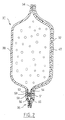
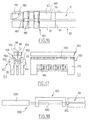
- a film 10 is routed to a FFS 100 machine.
- the FFS 100 machine includes a filling chute 110, drive means 112, 114 of the film 10, welding means longitudinal 120, blades 130, 132, first welding means 140, second welding means 150, tightening means 160 of a tube 20, guide means 180, holding means 170 and cutting means 190.
- the chute 110 has for example the shape of a cylinder of revolution hollow. Preferably, it is vertical.
- the drive means 112, 114 are for example constituted a belt which presses the film 10 on the external wall of the chute 110.
- the longitudinal welding means 120 are for example consisting of two sealing bars 122, 124 parallel to the axis of symmetry of revolution of the chute 110.
- the two blades 130, 132 are diametrically opposite with respect to to the axis of symmetry of revolution of the trough 110 and located near the lower part of the latter.
- the guide means 180 make it possible to guide a device for closure 50 to fix it to a bag 30.
- the first welding means 140, the second means of welding 150, the means of tightening 160 of the tube 20, the means of guide 180, the holding means 170 and the cutting means 190 will be described in detail later.
- the film 10 is wound around the filling chute 110 for form the tube 20.
- the film 10 has two longitudinal edges 12, 14 parallel to the direction of movement of the film 10. These longitudinal edges 12, 14 are brought together after the film 10 has enveloped the chute 110.
- the film 10 is then driven down the chute 110 filling by the drive means 112, 114.
- the longitudinal edges 12, 14 are then welded together by the longitudinal welding means 120.
- a weld is obtained longitudinal 32 continues.
- the tube 20 is formed. He is then trained towards the bottom of the chute 110.
- the tube 20 is then routed to the second means of welding 150 where the closing device 50 is fixed to the end of the tube located downstream of chute 110.
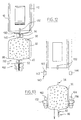
- the bag 30 formed by the process according to the invention includes walls 38, 40 and the closure device 50.
- the walls 38, 40 are formed by folding two elements of the film 10 in two longitudinal folds with reference to the direction of movement of the tube 20.
- the longitudinal edges 12, 14 are welded together by the longitudinal weld 32.
- a first transverse weld 34 and a second transverse weld 36 are made perpendicular to the longitudinal weld 32.
- the first weld 34 is made towards the end of the bag 30 closest to the filling chute 110.
- the second seal 36 is produced towards the end of the most away from the filling spout 110.
- the closing device 50 is arranged parallel to the second weld 36, close to the latter.
- the closing device 50 consists of two strips 51, 52 of closing.
- the strips 51, 52 respectively comprise a profile of female closure 53 and a male closure profile 54 able to cooperate with each other. On either side of these sections 53, 54 extend laterally sails 55, 56.
- These closing devices 50 can be of any form known to those skilled in the art.
- each strip 51, 52 can comprise one or more sections 53, 54.
- the webs 55, 56 can be joined to each other by a peelable weld, made on the side of the sections 53, 54 located towards the end of the bag 30 the further from chute 110.
- the closure device 50 comprises webs 55, 56 so united continues, over their entire length, to close the end of the bag 30 the further away from the chute 110, which then has in cross section a U-shaped.
- a peelable weld 57 is made parallel to the profiles 53, 54, towards the inside of the bag, between the sails 55, 56.
- the first 140 and second 150 welding means as well as the tightening means 160.
- the first welding means 140 are made, for example, of two sealing bars 142,144.
- the second welding means 150 consist, for example, of two sealing bars 152,154.
- the tightening means 160 consist, for example, of two bars tightening 162,164.
- the sealing bars 142,144 are suitable for move, in a back and forth movement between two positions in a plane perpendicular to the direction of movement of the tube 20. In one of these positions, they are spaced from each other by a distance greater than the diameter of the tube 20 (Fig. 13). In the other position, they are tightened on the parts of the film 10 intended to form the walls 38, 40 (Fig. 12). The same is true for the sealing bars 152, 154 and the tightening bars 162,164.
- the content of a sachet 30 can be poured into the chute 110 to fill a bag 30 after the tightening means 160 have, if necessary, tightened the walls 38, 40 of the tube 20, one on the other.
- the guide means 180 allow a string of closing devices 50 to be conveyed, transversely to the direction of movement of the tube 20.
- Each portion of the rosary corresponds to a closing device 50.
- the closing devices 50 are separated from each other by a space 58.
- the spaces 58 are cut out in the devices 50 in leaving material junctions 60 attaching the closure devices 50 to each other.
- end welds can be made 59, at each end of each device 50.
- Such an embodiment of the end welds 59 in particular facilitates the welding of each end of device 50 and walls 38, 40 by the second means of welding 150.
- the guide means 180 comprise grooved rollers 182 and a plate 188 for guiding the strips 51, 52 of the closure device 50.
- the plate 188 is vertical and parallel to the two bands 51, 52. It is located on the other side of the bands 51, 52, relative to the grooved rollers 182.
- the grooved casters 182 press the strips 51, 52 against the plate 188.
- another series of rollers 182 to groove replaces plate 188, so that the bands 51, 52 of the closing device are guided between the two sets of rollers 182 (figure 1).
- the grooved casters 182 have a cylinder shape of revolution, with a groove 183 formed all around the cylinder, halfway up of it. Profiles 53, 54 are housed in this groove 183 which allows thus to guide them.
- a knife 186 moves longitudinally with reference to the direction movement of the tube 20 between the guide means 180 and the second welding means 150.
- the knife 186 makes it possible to cut the chain of devices in portions by cutting the material junctions 60, after positioning a closing device 50 at the second welding means 150.
- the blade 130 is shown in more detail.
- the blade 130 pivots on an axis 133.
- This axis 133 is perpendicular to the direction of movement of the tube 20 and parallel to the tangent of the chute 110.
- the blade 130 pivots between two positions, one where it is parallel to the longitudinal axis of chute 110 and the other where it is perpendicular to this one. By switching between these two positions, the blade 130 creates a slot 42 in the film 10.
- the blade 132 creates the slot 44.
- the two pivoting blades 130, 132 cut out simultaneously the slots 42, 44 in the wall of the tube 20.
- These slots 42, 44 are diametrically opposed with respect to the longitudinal central axis of the chute 110 and at the same height of the tube 20. They facilitate the step of insertion of the closure strips 51, 52 between the walls 38.40 kept apart.
- the distance between each pair of slots 42, 44, in the longitudinal direction of the tube 20, with reference to its displacement, corresponds approximately to a length of sachet in this direction.
- the slots 42, 44 can also be created by other means suitable known in themselves by those skilled in the art.
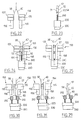
- FIGs 7 to 13 schematically represent the setting steps in place of the closing device 50 downstream of the chute 110.
- the tube 20 is tightened downstream of the chute 110 by the tightening means 160.
- the two walls of bags 38, 40 are generated.
- the walls 38, 40, intended to form a sachet are thus pressed, one on the other, over their entire length in the transverse direction in reference to the direction of movement of the tube 20, upstream of the position closure strips 51, 52.
- the walls 38, 40 are limited by a perpendicular sectioned end to the direction of movement of the tube 20. Near this end sectioned, the walls 38, 40 are separated from each other by the slots 42, 44 (Fig. 7).
- a closing device 50 is then routed and positioned by the guide means 180 between the separate walls 38, 40. Under the means holding 170, rollers 184 allow to drive and guide the closing device 50 between the walls 38, 40 (Fig. 9).
- the holding means 170 are then moved towards one another.
- the walls 38, 40 of the bag 30 are then welded, using the first welding means 140 which then tighten on the tube 20, transversely with reference to the direction of movement of the tube 20, at a distance approximately equal to the length of the bag 30 in this direction, upstream of the fixing position of the strips of closures 51, 52 (Fig. 12).
- the transverse weld 34 relative to the direction of movement of the tube 20 is formed (Fig. 13).
- a step of cutting the tube 20, transversely in reference to the direction of movement of the tube 20, at a distance approximately equal to the length of the bag 30 in this direction, upstream of the fastening position of the closure strips 51, 52 is operated by cutting means 190 located just above the first welding means 140. This makes it possible to separate the bag 30 thus completed from the rest of the tube 20 located upstream ( Figure 12).
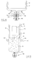
- An important element of the FFS machine for the implementation of the method according to the invention consists of the assembly formed of the second welding means 150, tightening means 160 and means holding 170.
- An example of such an assembly is shown in elevation. lateral in FIG. 14 and in cross section in FIG. 15.
- each bar 162, 164 of the means of constriction 160 extends rectilinearly, perpendicular to the direction of movement of the tube 20.
- the cross section of these bars 162, 164 is square. Their length is slightly greater than the dimension of a sachet in the direction transverse to the movement of the tube 20.
- the tightening means 160 can press the walls 38, 40 of the sachet one on the other over their entire length in the direction transverse with reference to the direction of movement of the tube 20. They are located upstream of the fastening position of the closing device 50 on the walls 38, 40.
- the second means of welding 150 and the holding means 170 are integral with one another.
- the holding elements 172, 174 are parallel to each other and transverse with reference to the displacement of the tube 20. They are formed each by an element 172, 174 in the shape of an inverted U.
- Each element 172, 174 has two branches 156, 158 parallel to the direction of displacement of the tube 20. They are approximately distant from the dimension of a bag 30 perpendicular to this direction.
- These branches 156, 158 constitute a first part of the welding means 150. They weld the ends of the closing device 50.
- the high ends of these branches 156, 158 are united by a bar transverse 155. This bar 155 constitutes both the holding means 172, 174 and a second part of the welding means 150 which allow to weld the walls 38, 40 to the webs 55, 56.
- the holding elements 172, 174 are pierced with orifices 176 opening onto the faces of these retaining elements 172, 174, which are in opposite and intended to be in contact with the walls 38, 40. Maintaining a walls 38, 40 on a retaining element 172, 174, is produced by suction through orifices 176 distributed thereon.
- the tube 20 is thus maintained by means of the retaining elements 172, 174, close to the severed end, before moving them apart (Fig. 14) to fix the two closure strips 51, 52 constituting a closure device 50 on the internal face of the walls 38, 40 intended to form a bag 30.
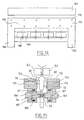
- a series of casters 184 is arranged, just below the bar 155, on a line transverse to the direction of movement of the tube 20.
- Each caster 184 rotates around an axis 187.
- the axes 187 of the rollers 184 are parallel to the direction of movement of the tube 20.
- the Casters 184 are arranged in pairs.
- the two casters 184 of each pair are located opposite each other on the closure device 50, at the level of the sections 53, 54.
- the axes 187 of the rollers 184 of each pair can remain at constant distance from each other, thanks to spring means 185.
- the rollers 184 of each pair remains at the same distance from each other, pressing on the closing device 50 at the level of the sections 53, 54.
- the rotation movement of the rollers 184 is synchronized with that of the grooved rollers 182 of the guide means 180.
- the strips of closure 51, 52 constituting the closure device 50 can be fixed on the external face of the walls 38, 40 intended to form the bag 30.
- the FFS machine for implementing the method according to the invention is then modified as illustrated in FIGS. 16 and 17.
- two closing devices 50 are represented. guided by guide means 180. These two closing devices 50 are linked to each other by a precut area 61. This area pre-cut can consist of a series of aligned holes and regularly spaced.
- the guide means 180 consist of grooved casters 182 similar to grooved casters 182 already described, as well as a plate 188.
- Separation means 189 make it possible to separate and guide the webs 55, 56 of the closing device 50, one from the other.
- These means of separation 189 consist of a nose 191 and two elements dividers 193.
- Each element 193 has the shape of a curved plate about an axis transverse to the direction of movement of the tube 20, the axes of the elements 193 being more distant from each other than the parts closest to the elements 193.
- the nose 191 is inserted between the sails 55, 56 and the elements 193 hold these sails 55, 56 apart on the other over the entire length of the closing device 50.
- the walls 38, 40 descend between the two elements 193.
- the area of the walls 38, 40 located near their severed end is engaged between the sails 55, 56.
- the elements 193 can then pivot around their axis longitudinal to clear the space between the walls 55, 56 and the walls 38, 40.
- the second welding means 150 can then tighten one on the other to weld the sails 55, 56 to the walls 38, 40.
- the webs 55, 56 can be only discarded just before entering the area of the means of welding 150 so as to pass on either side of all of the two walls 38, 40, before sliding on the edge of these walls 38, 40, to get into position before welding, using the rollers 184 or analogous means.
- the rollers 184 can be replaced by a guide 200. There are then several ways of positioning the device closing 50, at the walls 38, 40, using the guide 200.
- actuation means 230 are arranged on the opposite side of the second welding means 150 relative to to the guide means 180 (Fig. 18).
- the actuation means 230 move a rod 220 in a back and forth movement.
- Rod 220 provided with a clamp 210 then comes to seek the closing device 50.
- the clamp 210 can, for example, engage with a slider 80 (not shown in Figure 18), when the device 50 is provided.
- the device 50 is then pulled between the second welding means 150 by retraction of the rod 220 by means of the actuation means 230.
- the clamp 210 and the rod 220 hold the closing device 50 in position between the second welding means 152, 154 while these means welding 152, 154 close to perform the welding.
- the device closure 50 is thus in precise alignment with respect to the walls 38, 40.
- the second welding means 152, 154 weld the webs 55, 56 at the walls 38, 40, the two slots 42, 44 between them and the ends of the closure device 50. These ends in particular are welded to the walls 38, 40 by branches 156, 158. An opening cord can if necessary, fill the bag 30.
- the rod 220 supports the device 50 which is actuated by means arranged on the same side as the means of guide 180.
- the rod 220 is pushed between the second means of welding 152, 154 and thus causes a closing device 50.
- the rod 220 comprises a support 240 for closing device 50. It is actuated by actuating means 230, incorporated for example into the means of guide 180. ( Figures 19, 22 and 23). Rod 220 is located under the closing devices 50.
- the support 240 is movable between two positions ( Figures 19 and 21) thanks to a vertical back and forth movement. Rod 220 is positioned under the closing device 50 located at the entrance of the second welding means 150 and holding means 170.
- the support 240 is lifted so as to fit between the strips 51, 52 of this closing device 50 and support it by coming into contact with the profiles 53, 54 engaged in each other. Laterally, the support 240 is inserted between the two end welds 59 of this closure device 50.
- the closing device 50 is driven ( Figures 20 and 24). Once the closing device in position, it is welded to the walls 38, 40. Simultaneously with the welding of the webs 55, 56 on the walls 38, 40, the knife 186 cuts the junction 60 with the device closing 50 next. Then, the support 240 retracts into the rod 220 ( Figures 21 and 25). The rod 220 then returns to its initial position, with the support 240 positioned under the following closing device 50.
- the rod 220 comprises a clamp 210, This way can be used for example with a closing device 50 with slider 80.
- a closing device 50 is advanced just before the entry of the second welding means 150 and the means of maintenance 170 (Figure 26).
- the cursor 80 of this closing device 50 is in abutment against the end weld 59 of this device, the closest second welding means 150 and holding means 170.
- the clamp 210 is tightened on the slider 80 ( Figure 29).
- Ways actuation 230 advance the rod 220 which drives said device closure 50 ( Figures 27 and 30).
- the closing device 50 is then welded to the walls 38, 40.
- the clamp 210 is loosened ( Figures 28 and 31).
- the rod 220 then returns to its initial position under the device for closing 50 next.
- a step of cutting the tube 20 has been described above, transversely with reference to the direction of movement of the tube 20, at a distance approximately equal to the length of the bag 30 in this direction, upstream of the fastening position of the closure strips 51, 52. It is also possible to envisage a step of precutting the tube 20, transversely with reference to the direction of movement of the tube 20, at a distance approximately equal to the length of the bag 30 in this direction, upstream of the fastening position of the closure strips 51, 52. In this way the sachets 30 formed and filled by the process according to the invention remain attached to each other and will not be separated only later, by the user for example.
- this step of welding the walls 38, 40 between them, near the closure strips 51, 52 and the step of welding of the walls 38, 40, transversely to the direction of movement of the tube 20, downstream of the welding position above, are made by unique welding means suitable for back and forth between these two welding positions which are about a bag length 30 apart, in the direction of displacement of the tube 20.
- the step of cutting or precut is carried out by cutting means or pre-cut 190, integral with the first welding means 140.
- a cutting or precut step can also be carried out by means of cutting or precut 190 integral with the second means of welding 150.
- the cutting means or precut 190 may be integral with these.
- the step of fixing the strips of closures 51, 52 on the walls 38, 40 is achieved by means of independent fixing of the second welding means 150 or of the means unique welding.
- a step in the process according to the invention has been described above. consisting in pressing the walls 38, 40 intended to form the bag 30, one on the other, thanks to tightening means 160.
- These means of constriction 160 may be integral with the second welding means 150 or unique means of welding.
- the method of manufacturing the sachet according to the invention can be implemented work to fix closing strips 51, 52, provided with webs 55, 56 on which is deposited a heat-reactivatable adhesive.
Landscapes
- Engineering & Computer Science (AREA)
- Mechanical Engineering (AREA)
- Containers And Plastic Fillers For Packaging (AREA)
- Making Paper Articles (AREA)
Description
- acheminer un film sur une goulotte de remplissage d'une machine FFS pour former un tube en ramenant l'un sur l'autre les deux bords longitudinaux du film ;
- souder les bords longitudinaux du film en laissant une zone non soudée de quelques centimètre de large ;
- écarter les bords longitudinaux au niveau de la zone non soudée ;
- insérer une bande de fermeture montée sur un guide à l'intérieur du tube, par la zone non soudée ;
- souder le dispositif de fermeture sur la face interne des parois du tube ;
- retirer le guide du dispositif de fermeture ; et
- souder les bords longitudinaux du film, au niveau de la zone non soudée.
- avancer, en aval d'une goulotte de remplissage verticale, un tube apte à former des parois d'un sachet ;
- sectionner séquentiellement le tube en portions par une découpe globalement transversale par rapport à la direction de déplacement du tube,
- fixer un dispositif de fermeture sur l'extrémité sectionnée de la partie du tube, encore retenue sur la goulotte.
- des moyens pour avancer en aval d'une goulotte de remplissage verticale, un tube apte à former des parois d'un sachet,
- des moyens de fixation pour sectionner le tube globalement transversalement à sa direction de déplacement,
- des moyens de soudage pour souder un dispositif de fermeture sur l'extrémité de la partie sectionnée du tube encore retenue sur la goulotte.
- la figure 1 représente, en vue perspective, une machine FFS selon l'invention ;
- la figure 2 représente un sachet tel que formé par le procédé et sur la machine selon l'invention ;
- la figure 3 représente une variante du sachet représenté à la figure 2 ;
- la figure 4 est une vue schématique en élévation latérale, d'une machine FFS pour la mise en oeuvre du procédé selon l'invention ;
- la figure 5 est une vue schématique en élévation latérale, de la machine FFS pour la mise en oeuvre du procédé selon l'invention, tournée de 90° par rapport à la représentation de la figure 4 ;
- la figure 6 représente schématiquement, et de manière détaillée, des moyens de découpe latérale de la machine FFS pour la mise en oeuvre du procédé selon l'invention ;
- la figure 7 représente schématiquement, en coupe transversale, des moyens de maintien et de soudage de la machine FFS pour la mise en oeuvre du procédé selon l'invention ;
- la figure 8 représente schématiquement, en coupe transversale, les moyens représentés à la figure 7, à une étape ultérieure du procédé selon l'invention ;
- la figure 9 représente schématiquement, en coupe transversale, les moyens déjà représentés aux figures 7 et 8, à une étape ultérieure du procédé selon l'invention ;
- la figure 10 représente schématiquement, en coupe transversale, les moyens représentés aux figures 7, 8 et 9, à une étape ultérieure du procédé selon l'invention ;
- la figure 11 est une vue schématique, en élévation latérale, de la machine FFS selon l'invention à une étape ultérieure du procédé selon l'invention, par rapport à celle illustrée par la figure 10 ;
- la figure 12 est une vue schématique, en élévation latérale, de la machine FFS représentée à la figure 11, à une étape ultérieure du procédé selon l'invention ;
- la figure 13 est une vue schématique, en élévation latérale, de la machine FFS représentée à la figure 12, à une étape ultérieure du procédé selon l'invention ;
- la figure 14 représente schématiquement, vus en élévation latérale, les moyens de maintien et de soudage de la machine FFS pour la mise en oeuvre du procédé selon l'invention ;
- la figure 15 représente schématiquement en coupe transversale, les moyens de maintien et de soudage représentés à la figure 14 ;
- la figure 16 représente, en élévation latérale, une variante des moyens de guidage d'une machine FFS pour la mise en oeuvre du procédé selon l'invention ;
- la figure 17 représente schématiquement, en coupe, les moyens de soudage d'une variante de la machine FFS pour la mise en oeuvre du procédé selon l'invention; la figure 17a est une coupe transversale de tels moyens ; la figure 17b est une vue en élévation latérale de tels moyens ;
- la figure 18 est une vue en élévation latérale, d'une variante des moyens de guidage du dispositif de fermeture des sachets fabriqués par le procédé selon l'invention ;
- la figure 19 est une vue en élévation latérale d'une variante des moyens de guidage du dispositif de fermeture des sachets fabriqués par le procédé selon l'invention ;
- la figure 20 est une vue en élévation latérale, de la variante des moyens de guidage représentés à la figure 19, à une étape ultérieure du procédé selon l'invention ;
- la figure 21 est une vue en élévation latérale, de la variante des moyens de guidage représentés aux figures 19 et 20, à une étape ultérieure du procédé selon l'invention ;
- la figure 22 est une coupe schématique des moyens de guidage représentés aux figures 19 et 26, respectivement selon les coupes A-A et E-E ;
- la figure 23 est une coupe schématique des moyens représentés à la figure 19, selon la coupe B-B ;
- la figure 24 est une coupe schématique des moyens de guidage représentés à la figure 20, selon la coupe C-C ;
- la figure 25 est une coupe schématique des moyens de guidage représentés à la figure 21, selon la coupe D-D ;
- la figure 26 est une vue en élévation latérale, d'une autre variante des moyens de guidage du dispositif de fermetures de sachets fabriqués par le procédé selon l'invention ;
- la figure 27 est une vue en élévation latérale, de la variante des moyens de guidage représentés à la figure 26, à une étape ultérieure du procédé selon l'invention ;
- la figure 28 est une vue en élévation latérale des moyens de guidage représentés aux figures 26 et 27, à une étape ultérieure du procédé selon l'invention ;
- la figure 29 est une coupe schématique des moyens de guidage représentés à la figure 26, selon la coupe F-F ;
- la figure 30 est une coupe schématique des moyens de guidage représentés à la figure 27, selon la coupe G-G ; et
- la figure 31 est une coupe schématique des moyens de guidage représentés à la figure 28, selon la coupe H-H.
Claims (45)
- Procédé de fabrication, sur une machine (100) de formation, remplissage et fermeture automatiques, de sachets (30) comprenant les étapes consistant à :caractérisé en ce qu'il comprend en outre l'étape consistant à :avancer en aval d'une goulotte (110) de remplissage verticale, un tube (20) apte à former des parois (38, 40) d'un sachet (30) ;sectionner séquentiellement le tube (20) en portions par une découpe globalement transversale par rapport à la direction de déplacement du tube (20) ;fixer un dispositif de fermeture (50) sur l'extrémité sectionnée de la partie du tube (20), encore retenue sur la goulotte (110).
- Procédé de fabrication de sachets (30), selon la revendication 1, caractérisé en ce qu'il est utilisé pour fixer deux bandes de fermeture (51, 52) constitutives du dispositif de fermeture (50) sur la face externe des parois (38, 40) destinées à former un sachet (30).
- Procédé de fabrication de sachets (30) selon la revendication 1, caractérisé en ce qu'il est utilisé pour fixer des bandes de fermetures (51, 52) constitutives du dispositif de fermeture (50), sur la face interne des parois (38, 40) destinées à former un sachet (30).
- Procédé de fabrication de sachets (30) selon la revendication 3, caractérisé en ce qu'il comprend l'étape consistant à maintenir le tube (20), à proximité de l'extrémité sectionnée, à l'aide de deux éléments de maintien (172, 174) parallèles entre eux et transversaux en référence au déplacement du tube (20) et écarter les éléments de maintien (172, 174) pour fixer les deux bandes de fermeture (51, 52) constitutives d'un dispositif de fermeture (50) sur la face interne des parois (38, 40) destinées à former un sachet 30.
- Procédé de fabrication de sachets (30), selon l'une quelconque des revendications précédentes, caractérisé en ce qu'il comprend en outre, les étapes consistant à :presser les parois (38, 40) destinées à former le sachet (30), l'une sur l'autre, sur toute leur longueur dans la direction transversale en référence à la direction de déplacement du tube (20), en amont de la position de fixation des bandes de fermeture(51, 52) ; età remplir le sachet (30), en aval de la position de pressage de l'étape précédente, par la goulotte de remplissage (110).
- Procédé de fabrication de sachets (30), selon l'une quelconque des revendications 3-5, caractérisé en ce qu'il comprend en outre, une étape de découpe de deux fentes (42, 44) dans la paroi du tube (20), diamétralement opposées par rapport à l'axe central longitudinal de la goulotte (110), à la même hauteur du tube (20), afin de faciliter l'étape d'insertion des bandes de fermeture (51, 52) entre les parois (38, 40) maintenues écartées.
- Procédé de fabrication de sachets (30) selon l'une quelconque des revendications précédentes, caractérisé en ce qu'il comprend, en outre, une étape de coupe ou prédécoupe du tube (20), transversalement en référence à la direction de déplacement du tube (20), à une distance approximativement égale à la longueur du sachet (30) dans cette direction, en amont de la position de fixation des bandes de fermeture (51, 52).
- Procédé de fabrication de sachets (30) selon l'une quelconque des revendications précédentes, caractérisé en ce qu'il comprend, en outre, une étape consistant à souder les parois (38, 40) du sachet (30), à l'aide de premiers moyens de soudage (140), transversalement en référence à la direction de déplacement du tube (20), à une distance approximativement égale à la longueur du sachet (30) dans cette direction, en amont de la position de fixation des bandes de fermeture (51, 52).
- Procédé de fabrication de sachets (30) selon l'une quelconque des revendications précédentes, caractérisé en ce qu'il comprend, en outre, une étape de coupe ou prédécoupe du tube (20) à proximité des bandes de fermeture (51, 52), transversalement en référence à la direction de déplacement du tube (20).
- Procédé de fabrication de sachets (30) selon l'une quelconque des revendications précédentes, caractérisé en ce qu'une étape de soudage des parois (38, 40) est réalisée par des seconds moyens de soudage (150), aptes à effectuer une soudure (36) des parois entre elles, à proximité de la position de fixation des bandes de fermeture (51, 52), globalement transversalement en référence à la direction de déplacement du tube (20).
- Procédé de fabrication de sachets (30) selon l'une quelconque des revendications 1 à 7 et 9, caractérisé en ce qu'une étape de soudage des parois (38, 40) entre elles, à proximité des bandes de fermeture (51,52) et une étape de soudage des parois (38, 40) en aval de la position de soudage précédente sont réalisées par des moyens uniques de soudage aptes à effectuer un mouvement de va et vient entre deux positions de soudage distantes d'environ une longueur de sachet (30), dans la direction de déplacement du tube (20).
- Procédé de fabrication de sachets (30) selon la revendication 7, prise en combinaison avec la revendication 8 ou avec la revendication 10, caractérisé en ce qu'une étape de coupe ou prédécoupe est réalisée par des moyens de coupe ou prédécoupe (190) solidaires des premiers moyens de soudage (140).
- Procédé de fabrication de sachets (30) selon la revendication 9, prise en combinaison avec la revendication 10, caractérisé en ce qu'une étape de coupe ou prédécoupe est réalisée par des moyens de coupe ou prédécoupe (190) solidaires des seconds moyens de soudage (150).
- Procédé de fabrication de sachets (30) selon l'une quelconque des revendications 7 et 9, prise en combinaison avec la revendication 11, caractérisé en ce que chaque étape de coupe ou prédécoupe est réalisée par des moyens de coupe ou prédécoupe (190) solidaires des moyens uniques de soudage.
- Procédé de fabrication de sachets (30) selon l'une quelconque des revendications 10 à 14, caractérisé en ce que l'étape de fixation des bandes de fermeture (51, 52) est réalisée par des moyens de fixation indépendants des seconds moyens de soudage (150) ou des moyens uniques de soudage.
- Procédé de fabrication de sachets (30) selon l'une quelconque des revendications 5 à 15, caractérisé en ce que l'étape consistant à presser les parois (38, 40) du sachet (30) l'une sur l'autre est réalisée grâce à des moyens de resserrement (160) solidaires des seconds moyens de soudage (150) ou des moyens uniques de soudage.
- Procédé de fabrication de sachets (30) selon l'une quelconque des revendications précédentes, caractérisé en ce qu'il est mis en oeuvre pour fixer des bandes de fermeture (51, 52) munies de voiles (55, 56) sur lesquelles est déposé un adhésif thermo-réactivable.
- Procédé de fabrication de sachets (30) selon l'une quelconque des revendications précédentes, caractérisé en ce qu'il est mis en oeuvre pour fixer des bandes de fermeture (51, 52) unies sur toute leur longueur par un voile ayant en coupe transverse une forme de U.
- Procédé de fabrication de sachets (30) selon l'une quelconque des revendications 3-18, caractérisé en ce qu'il est mis en oeuvre pour fixer des bandes de fermeture (51, 52) munies chacune, sur toute leur longueur, de voiles (55, 56) aptes à être scellés l'un à l'autre, à l'intérieur du sachet (30) par une soudure pelable.
- Procédé de fabrication de sachets (30) selon l'une quelconque des revendications 4 à 19, caractérisé par le fait que l'étape de maintien des parois (38, 40) est réalisée par aspiration à travers des orifices (176) répartis sur les éléments de maintien (172, 174).
- Procédé de fabrication de sachets (30) selon l'une des revendications 3-20, caractérisé par le fait qu'il comprend en outre une étape consistant à positionner le dispositif de fermeture (50), entre les parois (38, 40) séparées.
- Procédé de fabrication de sachets (30) selon la revendication 21, caractérisé par le fait que l'étape consistant à positionner le dispositif de fermeture (50) est réalisée à l'aide d'une tige (220) munie d'une pince (210), mue dans un mouvement de va et vient par des moyens d'actionnement (230).
- Procédé de fabrication de sachets (30) selon la revendication 21, caractérisé par le fait que l'étape consistant à positionner le dispositif de fermeture (50) est réalisée à l'aide d'une tige (220) comprenant un support (240) de dispositif de fermeture (50), ce support (240) étant mobile, entre deux positions, dans un mouvement de va et vient, et s'insérant, lorsqu'il est levé, entre les bandes (51, 52) et les soudures d'extrémité (59), de manière à entraíner le dispositif de fermeture (50) sous les seconds moyens de soudage (150), lorsque les moyens d'actionnement (230) font avancer la tige (220).
- Procédé selon l'une des revendications 1 à 23, caractérisé par le fait qu'il est utilisé pour fixer un dispositif de fermeture (50) muni d'un curseur (80).
- Machine de formation, remplissage et fermeture automatiques de sachets (30) pour la mise en oeuvre du procédé selon l'une quelconque des revendications précédentes, comprenant :caractérisée par le fait qu'elle comprend, en outre :des moyens pour avancer en aval d'une goulotte de remplissage (110) verticale, un tube (20) apte à former des parois (38, 40) d'un sachet (30),des moyens de découpe (190) pour sectionner le tube (20) globalement transversalement à sa direction de déplacement,des moyens de soudage (150) pour souder un dispositif de fermeture (50) sur l'extrémité de la partie sectionnée du tube (20) encore retenue sur la goulotte (110).
- Machine selon la revendication 25, caractérisée en ce qu'elle comprend en outre des moyens de maintien (170) du film (10), s'étendant transversalement en référence au sens de déplacement du tube (20).
- Machine selon l'une quelconque des revendications 25 et 26, caractérisée en ce qu'elle comprend des moyens de resserrement (160) pour presser les parois (38, 40) du sachet, l'une sur l'autre, sur toute leur longueur dans la direction transversale en référence au sens de déplacement du tube (20), ces moyens étant situés en amont de la position de fixation du dispositif de fermeture (50) sur les parois (38, 40).
- Machine selon l'une quelconque des revendications 25 à 27, caractérisée en ce qu'elle comprend deux lames (130, 132) diamétralement opposées par rapport à l'axe de symétrie de révolution de la goulotte (110) et situées à proximité de la partie basse de cette dernière.
- Machine selon l'une quelconque des revendications 25 à 28, caractérisée en ce qu'elle comprend des moyens de coupe ou prédécoupe (190) du tube (20) en amont de la position de fixation des bandes de fermeture (51, 52) sur les parois (38, 40), distants de cette position, approximativement de la longueur du sachet (30), dans la direction longitudinale en référence à la direction de déplacement du tube (20), pour effectuer une coupe ou une prédécoupe globalement perpendiculaire à cette direction.
- Machine selon l'une quelconque des revendications 25 à 29, caractérisée en ce qu'elle comprend des premiers moyens de soudage (140) des parois (38, 40) du sachet (30) en amont de la position de fixation des bandes de fermeture (51, 52) sur les parois (38, 40), distants de cette position, approximativement de la longueur du sachet (30), dans la direction longitudinale en référence à la direction du déplacement du tube (20), pour effectuer une soudure (34) globalement perpendiculaire à cette direction.
- Machine selon l'une quelconque des revendications 25 à 30, caractérisée en ce qu'elle comprend des moyens de coupe ou prédécoupe (190) à proximité des bandes de fermeture (51, 52), pour effectuer une coupe ou une prédécoupe transversalement en référence à la direction de déplacement du tube (20).
- Machine selon l'une quelconque des revendications 25 à 31, caractérisée en ce qu'elle comprend des seconds moyens de soudage (150) aptes à effectuer une soudure (36) des parois (38, 40) entre elles, à proximité de la position de fixation des bandes de fermeture (51, 52) sur les parois (38, 40), globalement transversalement en référence à la direction de déplacement du tube.
- Machine selon l'une quelconque des revendications 25 à 29 et 31, caractérisée en ce qu'elle comprend des moyens uniques de soudage, aptes à effectuer une soudure (36) des parois (38, 40) entre elles, à proximité des bandes de fermeture (51, 52) et une soudure (34) des parois (38, 40) entre elles en aval de la soudure (36) précédente avec un mouvement de va et vient entre les positions des deux soudures (34, 36), ces positions étant distantes d'environ une longueur de sachet (30) dans la direction de déplacement du tube (20), et les soudures (34, 36) étant globalement transversales en référence à cette direction.
- Machine selon la revendication 29 prise en combinaison avec la revendication 30 ou la revendication 32, caractérisée en ce que les moyens de coupe ou prédécoupe (190) sont solidaires des premiers moyens de soudage (140).
- Machine selon la revendication 31, prise en combinaison avec la revendication 29, caractérisée en ce que les moyens de coupe ou prédécoupe (190) sont solidaires des seconds moyens de soudage (150).
- Machine selon l'une quelconque des revendications 29 et 31, prise en combinaison avec la revendication 33, caractérisée en ce que les moyens de coupe ou prédécoupe (190) sont solidaires des moyens uniques de soudage.
- Machine selon l'une des revendications 32 à 36, caractérisée en ce que qu'elle comprend des moyens de fixation des bandes de fermeture indépendants des seconds moyens de soudage (150) ou des moyens uniques de soudage.
- Machine selon l'une quelconque des revendications 27 à 37, caractérisée en ce que les moyens de resserrement (160) sont solidaires des seconds moyens de soudage (150) ou des moyens uniques de soudage.
- Machine selon l'une quelconque des revendications 26 à 38, caractérisée en ce que des orifices d'aspiration (176) du film (10) sont répartis sur les éléments de maintien (172, 174).
- Machine selon l'une quelconque des revendications 26 à 39, caractérisée en ce que les moyens de maintien (170) sont solidaires des seconds moyens de soudage (150) ou des moyens uniques de soudage.
- Machine selon l'une quelconque des revendications 25 à 40, caractérisée en ce qu'elle comprend des moyens de guidage (180) et d'avancée des bandes de fermeture (50) munies de roulettes (182).
- Machine selon l'une des revendications 25 à 41, caractérisée par le fait qu'elle comprend une tige (220) munie d'une pince (210), mue dans un mouvement de va et vient par des moyens d'actionnement (230).
- Machine selon la revendication 42, caractérisée par le fait que la pince (210) vient en prise avec un curseur (80) munissant le dispositif (50).
- Machine selon l'une des revendications 25 à 41, caractérisée par le fait qu'elle comprend une tige (220) comprenant un support (240) de dispositif de fermeture (50), ce support (240) étant mobile, entre deux positions, dans un mouvement de va et vient, et s'insérant lorsqu'il est levé, entre les bandes (51, 52) et les soudures d'extrémité (59), de manière à entraíner le dispositif de fermeture (50) sous les seconds moyens de soudage (150) lorsque les moyens d'actionnement (230) font avancer la tige (220).
- Machine selon l'une quelconque des revendications 24 à 44, caractérisée en ce qu'elle comprend des moyens de séparation (189) permettant d'écarter l'un de l'autre et guider les voiles (55, 56) d'un dispositif de fermeture (50).
Applications Claiming Priority (2)
| Application Number | Priority Date | Filing Date | Title |
|---|---|---|---|
| FR9802887A FR2775953B1 (fr) | 1998-03-10 | 1998-03-10 | Procede et machine de formation de sachets avec fermeture a profiles transversaux |
| FR9802887 | 1998-03-10 |
Publications (2)
| Publication Number | Publication Date |
|---|---|
| EP0941928A1 EP0941928A1 (fr) | 1999-09-15 |
| EP0941928B1 true EP0941928B1 (fr) | 2001-08-29 |
Family
ID=9523844
Family Applications (1)
| Application Number | Title | Priority Date | Filing Date |
|---|---|---|---|
| EP99400548A Expired - Lifetime EP0941928B1 (fr) | 1998-03-10 | 1999-03-08 | Procédé et machine de formation de sachets avec fermeture à profilés transversaux |
Country Status (4)
| Country | Link |
|---|---|
| US (1) | US6000197A (fr) |
| EP (1) | EP0941928B1 (fr) |
| DE (1) | DE69900236T2 (fr) |
| FR (1) | FR2775953B1 (fr) |
Families Citing this family (41)
| Publication number | Priority date | Publication date | Assignee | Title |
|---|---|---|---|---|
| US6216423B1 (en) | 1997-11-07 | 2001-04-17 | Huntsman Kcl Corporation | Method and apparatus for placing a product in a flexible recloseable container |
| US5956924A (en) | 1997-11-07 | 1999-09-28 | Rcl Corporation | Method and apparatus for placing a product in a flexible recloseable container |
| FR2778362B1 (fr) * | 1998-05-05 | 2000-07-28 | Flexico France Sarl | Procede de realisation de sachets comportant des profiles de fermeture actionnes par curseur |
| US7254873B2 (en) | 1998-06-04 | 2007-08-14 | Illinois Tool Works, Inc. | Scored tamper evident fastener tape |
| US6131369A (en) * | 1998-10-22 | 2000-10-17 | Illinois Tool Works Inc. | Method of applying slider to package having reclosable zipper |
| US6151868A (en) * | 1999-01-19 | 2000-11-28 | Illinois Tool Works, Inc. | Transverse direction zipper attaching apparatus and method |
| US7101079B2 (en) | 1999-05-11 | 2006-09-05 | Sargento Foods, Inc. | Resealable bag for filling with food product(s) and method |
| US6360513B1 (en) | 1999-05-11 | 2002-03-26 | Sargento Foods Inc. | Resealable bag for filling with food product(s) and method |
| US6286999B1 (en) | 1999-05-11 | 2001-09-11 | Pactiv Corporation | Tamper-evident reclosable bag |
| US6244021B1 (en) * | 1999-05-21 | 2001-06-12 | Illinois Tool Works Inc. | Method of applying reclosable zipper to package |
| US6327837B1 (en) * | 1999-07-15 | 2001-12-11 | Illinois Tool Works Inc. | Slide-zipper assembly with peel seal and method of making packages with slide zipper assembly |
| US6477820B1 (en) | 1999-07-29 | 2002-11-12 | Kraft Foods Holdings, Inc. | Method of making a package with a zipper closure |
| US6071011A (en) * | 1999-08-12 | 2000-06-06 | Tenneco Packaging, Inc. | Fill-through-the-top package |
| US6665999B1 (en) * | 1999-09-07 | 2003-12-23 | Recot, Inc. | Seal jaw modules for reclose bag modification to vertical form, fill, and seal packaging system |
| US7067037B2 (en) * | 1999-10-12 | 2006-06-27 | Com-Pac International, Inc | Modular reciprocating heat seal jaw assembly |
| US6361212B1 (en) | 1999-10-18 | 2002-03-26 | Com-Pac International, Inc. | Top opening reclosable bag and method of manufacture thereof |
| US6467956B1 (en) * | 2000-04-05 | 2002-10-22 | Reynolds Consumer Products, Inc. | Tamper evident package having slider device, and methods |
| US6530870B2 (en) | 2000-04-27 | 2003-03-11 | Reynolds Consumer Products, Inc. | Methods of manufacturing reclosable packages; and packages made thereby |
| US6616333B2 (en) | 2000-09-22 | 2003-09-09 | Kraft Foods Holdings, Inc. | Fastener closure arrangement for flexible packages |
| US20020094137A1 (en) * | 2001-01-16 | 2002-07-18 | Schneider John H. | Tamper evident resealable packaging |
| US6675558B2 (en) | 2001-04-18 | 2004-01-13 | Kraft Foods Holdings, Inc. | Method for manufacturing flexible packages having slide closures |
| US6688080B2 (en) | 2001-04-18 | 2004-02-10 | Kraft Foods Holdings, Inc. | Method for manufacturing flexible packages having slide closures |
| US6820393B2 (en) | 2001-04-18 | 2004-11-23 | Kraft Foods Holdings, Inc. | Apparatus for manufacturing flexible packages having slide closures |
| US6688079B2 (en) | 2001-04-18 | 2004-02-10 | Kraft Foods Holdings, Inc. | Method for manufacturing flexible packages having slide closures |
| US6769229B2 (en) | 2001-08-30 | 2004-08-03 | Kraft Foods Holdings, Inc. | Method for manufacturing flexible packages having slide closures |
| WO2003106273A2 (fr) | 2002-06-17 | 2003-12-24 | Pliant Corporation | Sac a fermeture coulissante a joint pelable |
| US6863646B2 (en) | 2002-06-19 | 2005-03-08 | Kraft Foods Holdings, Inc. | Reclosable system for flexible packages having interlocking fasteners |
| US6884207B2 (en) | 2002-10-25 | 2005-04-26 | Kraft Foods Holdings, Inc. | Fastener closure arrangement for flexible packages |
| US6939041B2 (en) | 2003-01-29 | 2005-09-06 | Kraft Foods Holdings, Inc. | Fastener closure arrangement for flexible packages |
| US7306370B2 (en) | 2003-07-31 | 2007-12-11 | Kraft Foods Holdings, Inc. | Shrouded flexible packages |
| US8122687B2 (en) | 2003-07-31 | 2012-02-28 | Kraft Foods Global Brands Llc | Method of making flexible packages having slide closures |
| US7481580B2 (en) * | 2004-10-01 | 2009-01-27 | Reynolds Consumer Products, Inc. | Reclosable flexible package with displaceable tamper-evident structure |
| US7553083B2 (en) * | 2005-03-15 | 2009-06-30 | Illinois Tool Works Inc. | Reclosable packages with front panel opening |
| US8714819B2 (en) | 2005-10-31 | 2014-05-06 | Global Packaging Solutions Limited | Reclosable fastener |
| US8096022B2 (en) * | 2005-10-31 | 2012-01-17 | Global Packaging Solutions Limited | Reclosable container and method of manufacture |
| US7437805B2 (en) | 2006-06-23 | 2008-10-21 | Edward Alan Berich | Reclosable storage bag closure with internal valving |
| WO2008107495A1 (fr) * | 2007-03-08 | 2008-09-12 | Ulma Packaging Technological Center, S. Coop. | Système et procédé d'emballage vertical |
| US20100284633A1 (en) * | 2009-05-07 | 2010-11-11 | Cmd Corporation | Discrete pouch having a closure system secured thereto |
| US8128545B2 (en) * | 2009-05-07 | 2012-03-06 | Cmd Corporation | Machine for securing a closure system onto a discrete pouch |
| US8128546B2 (en) | 2009-05-07 | 2012-03-06 | Cmd Corporation | In-line method for securing a closure system onto a discrete pouch |
| US20100331158A1 (en) * | 2009-06-30 | 2010-12-30 | Cmd Corporation | Method and Apparatus For Applying Closures To Pouches |
Family Cites Families (13)
| Publication number | Priority date | Publication date | Assignee | Title |
|---|---|---|---|---|
| US4655862A (en) * | 1984-01-30 | 1987-04-07 | Minigrip, Incorporated | Method of and means for making reclosable bags and method therefor |
| US4617683A (en) * | 1984-01-30 | 1986-10-14 | Minigrip, Inc. | Reclosable bag, material, and method of and means for making same |
| US4709398A (en) * | 1987-01-07 | 1987-11-24 | Minigrip, Inc. | Chain bags, method and apparatus |
| US4878987A (en) * | 1987-03-16 | 1989-11-07 | Minigrip, Inc. | Transverse zipper bag material and method of and means for making same |
| US4894975A (en) | 1988-03-09 | 1990-01-23 | Minigrip, Inc. | Method and apparatus for making reclosable bags with fastener strips in a form fill and seal machine |
| US4844759A (en) * | 1988-05-13 | 1989-07-04 | Minigrip, Inc. | Method of and means for applying reclosable fasteners to plastic film |
| US4909017B1 (en) * | 1989-07-28 | 1999-02-09 | Minigrip Inc | Reclosable bag material method and apparatus |
| CA2070937C (fr) | 1991-08-09 | 1998-09-15 | Paul Tilman | Sacs de plastique reutilisables et methode de fabrication au moyen d'une bande dechirable discontinue |
| US5111643A (en) * | 1991-08-23 | 1992-05-12 | Sun-Maid Growers Of California | Apparatus and fastener supply strip for attaching reclosable fastener to plastic bags |
| US5564259A (en) * | 1992-05-22 | 1996-10-15 | Kcl Corporation | Method and apparatus for resealable closure addition to form, fill and seal bag |
| US5557907A (en) * | 1995-02-24 | 1996-09-24 | Illinois Tool Works Inc. | Transverse zipper system |
| US5776045A (en) * | 1995-11-06 | 1998-07-07 | Lakeland Micro, Inc. | Machine for attaching a reclosable fastener to a flexible material |
| FR2745261B1 (fr) * | 1996-02-27 | 1998-05-07 | Flexico France Sarl | Machine de formation, remplissage et fermeture automatique de sacs, a profiles de fermeture transversaux |
-
1998
- 1998-03-10 FR FR9802887A patent/FR2775953B1/fr not_active Expired - Fee Related
- 1998-10-22 US US09/177,212 patent/US6000197A/en not_active Expired - Lifetime
-
1999
- 1999-03-08 EP EP99400548A patent/EP0941928B1/fr not_active Expired - Lifetime
- 1999-03-08 DE DE69900236T patent/DE69900236T2/de not_active Expired - Fee Related
Also Published As
| Publication number | Publication date |
|---|---|
| DE69900236T2 (de) | 2002-06-13 |
| EP0941928A1 (fr) | 1999-09-15 |
| FR2775953B1 (fr) | 2000-06-02 |
| DE69900236D1 (de) | 2001-10-04 |
| US6000197A (en) | 1999-12-14 |
| FR2775953A1 (fr) | 1999-09-17 |
Similar Documents
| Publication | Publication Date | Title |
|---|---|---|
| EP0941928B1 (fr) | Procédé et machine de formation de sachets avec fermeture à profilés transversaux | |
| EP0951989B1 (fr) | Procédé de formation de sachets d'emballage avec dispositif de fermeture | |
| EP0792802B1 (fr) | Machine de formation, remplissage et fermeture automatique de sacs, à profiles de fermeture transversaux | |
| EP0938427A2 (fr) | Machine de formation, remplissage et fermeture de sacs, a profiles de fermeture transversaux | |
| FR2584676A1 (fr) | Systeme automatique de remplissage et d'emballage | |
| CH438141A (fr) | Appareil pour ouvrir des sacs en vue de leur remplissage | |
| CH630025A5 (fr) | Chapelet de recipients identiques souples en matiere synthetique, et son procede de fabrication. | |
| EP0906866A1 (fr) | Procédé et machine de fabrication automatique de sachets, ainsi que les sachets obtenus | |
| EP0626921B1 (fr) | Recipient en matiere souple, procede et installation pour sa fabrication | |
| FR2574050A1 (fr) | Dispositif de soudage transversal d'emballages | |
| FR2501628A1 (fr) | Procede et dispositif pour ouvrir et charger des recipients flexibles | |
| EP0915019A1 (fr) | Procédé de fabrication de sacs et de conditionnement | |
| FR2772004A1 (fr) | Machine de formation, remplissage et fermeture automatique de sacs, a profiles de fermeture transversaux | |
| FR2765191A1 (fr) | Procede et machine de collage automatique d'un film plastique thermoretractable sur le fond d'une caisse ouverte | |
| EP0938968A1 (fr) | Procédé et dispositif de formation de fermetures étanches pour sachets | |
| BE1004578A3 (fr) | Procede et appareil pour la fabrication de sachets tetraedre pour le the. | |
| FR2781718A1 (fr) | Procede de fabrication de sacs a fond plat et machine pour sa mise en oeuvre | |
| FR2565201A1 (fr) | Procede et installation pour l'emballage d'un paquet a l'aide d'une feuille d'emballage et les paquets emballes obtenus | |
| FR2518496A1 (fr) | Dispositif pour l'alimentation en etiquettes et vignettes analogues | |
| EP0004631B1 (fr) | Dispositif et procédé d'empaquetage | |
| EP0689993A1 (fr) | Machine d'emballage utilisant un film souple ainsi que l'emballage obtenu | |
| BE1006030A5 (fr) | Procede pour l'emballage d'articles divers a l'aide d'un film plastique etirable et machine pour la realisation dudit procede. | |
| FR2826606A1 (fr) | Procede de reunion de sachets, dispositif pour la mise en oeuvre du procede et chaine de sachets ainsi que chaine de sachets empiles | |
| BE515333A (fr) | ||
| FR2848986A1 (fr) | Procede d'habillage de produits avec des manchons etirable et installation pour la pose de tels manchons |
Legal Events
| Date | Code | Title | Description |
|---|---|---|---|
| PUAI | Public reference made under article 153(3) epc to a published international application that has entered the european phase |
Free format text: ORIGINAL CODE: 0009012 |
|
| AK | Designated contracting states |
Kind code of ref document: A1 Designated state(s): BE DE ES FR GB IT NL |
|
| AX | Request for extension of the european patent |
Free format text: AL;LT;LV;MK;RO;SI |
|
| 17P | Request for examination filed |
Effective date: 20000306 |
|
| AKX | Designation fees paid |
Free format text: BE DE ES FR GB IT NL |
|
| GRAG | Despatch of communication of intention to grant |
Free format text: ORIGINAL CODE: EPIDOS AGRA |
|
| 17Q | First examination report despatched |
Effective date: 20001108 |
|
| GRAG | Despatch of communication of intention to grant |
Free format text: ORIGINAL CODE: EPIDOS AGRA |
|
| GRAH | Despatch of communication of intention to grant a patent |
Free format text: ORIGINAL CODE: EPIDOS IGRA |
|
| GRAH | Despatch of communication of intention to grant a patent |
Free format text: ORIGINAL CODE: EPIDOS IGRA |
|
| GRAA | (expected) grant |
Free format text: ORIGINAL CODE: 0009210 |
|
| AK | Designated contracting states |
Kind code of ref document: B1 Designated state(s): BE DE ES FR GB IT NL |
|
| PG25 | Lapsed in a contracting state [announced via postgrant information from national office to epo] |
Ref country code: NL Free format text: LAPSE BECAUSE OF FAILURE TO SUBMIT A TRANSLATION OF THE DESCRIPTION OR TO PAY THE FEE WITHIN THE PRESCRIBED TIME-LIMIT Effective date: 20010829 Ref country code: IT Free format text: LAPSE BECAUSE OF FAILURE TO SUBMIT A TRANSLATION OF THE DESCRIPTION OR TO PAY THE FEE WITHIN THE PRESCRIBED TIME-LIMIT;WARNING: LAPSES OF ITALIAN PATENTS WITH EFFECTIVE DATE BEFORE 2007 MAY HAVE OCCURRED AT ANY TIME BEFORE 2007. THE CORRECT EFFECTIVE DATE MAY BE DIFFERENT FROM THE ONE RECORDED. Effective date: 20010829 |
|
| REF | Corresponds to: |
Ref document number: 69900236 Country of ref document: DE Date of ref document: 20011004 |
|
| REG | Reference to a national code |
Ref country code: GB Ref legal event code: IF02 |
|
| GBT | Gb: translation of ep patent filed (gb section 77(6)(a)/1977) |
Effective date: 20011130 |
|
| NLV1 | Nl: lapsed or annulled due to failure to fulfill the requirements of art. 29p and 29m of the patents act | ||
| PG25 | Lapsed in a contracting state [announced via postgrant information from national office to epo] |
Ref country code: ES Free format text: LAPSE BECAUSE OF FAILURE TO SUBMIT A TRANSLATION OF THE DESCRIPTION OR TO PAY THE FEE WITHIN THE PRESCRIBED TIME-LIMIT Effective date: 20020228 |
|
| PG25 | Lapsed in a contracting state [announced via postgrant information from national office to epo] |
Ref country code: BE Free format text: LAPSE BECAUSE OF NON-PAYMENT OF DUE FEES Effective date: 20020331 |
|
| PLBE | No opposition filed within time limit |
Free format text: ORIGINAL CODE: 0009261 |
|
| STAA | Information on the status of an ep patent application or granted ep patent |
Free format text: STATUS: NO OPPOSITION FILED WITHIN TIME LIMIT |
|
| 26N | No opposition filed | ||
| BERE | Be: lapsed |
Owner name: *FLEXICO-FRANCE Effective date: 20020331 |
|
| PGFP | Annual fee paid to national office [announced via postgrant information from national office to epo] |
Ref country code: DE Payment date: 20070410 Year of fee payment: 9 |
|
| PGFP | Annual fee paid to national office [announced via postgrant information from national office to epo] |
Ref country code: GB Payment date: 20070416 Year of fee payment: 9 |
|
| PGFP | Annual fee paid to national office [announced via postgrant information from national office to epo] |
Ref country code: FR Payment date: 20070328 Year of fee payment: 9 |
|
| GBPC | Gb: european patent ceased through non-payment of renewal fee |
Effective date: 20080308 |
|
| REG | Reference to a national code |
Ref country code: FR Ref legal event code: ST Effective date: 20081125 |
|
| PG25 | Lapsed in a contracting state [announced via postgrant information from national office to epo] |
Ref country code: DE Free format text: LAPSE BECAUSE OF NON-PAYMENT OF DUE FEES Effective date: 20081001 |
|
| PG25 | Lapsed in a contracting state [announced via postgrant information from national office to epo] |
Ref country code: FR Free format text: LAPSE BECAUSE OF NON-PAYMENT OF DUE FEES Effective date: 20080331 |
|
| PG25 | Lapsed in a contracting state [announced via postgrant information from national office to epo] |
Ref country code: GB Free format text: LAPSE BECAUSE OF NON-PAYMENT OF DUE FEES Effective date: 20080308 |