EP0941904A2 - Computersteuerung vom Betrieb einer Schienenfahrzeug-Bremsanlage - Google Patents
Computersteuerung vom Betrieb einer Schienenfahrzeug-Bremsanlage Download PDFInfo
- Publication number
- EP0941904A2 EP0941904A2 EP98119185A EP98119185A EP0941904A2 EP 0941904 A2 EP0941904 A2 EP 0941904A2 EP 98119185 A EP98119185 A EP 98119185A EP 98119185 A EP98119185 A EP 98119185A EP 0941904 A2 EP0941904 A2 EP 0941904A2
- Authority
- EP
- European Patent Office
- Prior art keywords
- pressure
- train
- brake pipe
- brake
- locomotive
- Prior art date
- Legal status (The legal status is an assumption and is not a legal conclusion. Google has not performed a legal analysis and makes no representation as to the accuracy of the status listed.)
- Withdrawn
Links
- 230000003137 locomotive effect Effects 0.000 claims abstract description 67
- 230000008859 change Effects 0.000 claims abstract description 43
- 230000007423 decrease Effects 0.000 claims abstract description 18
- 238000000034 method Methods 0.000 claims description 67
- 238000012360 testing method Methods 0.000 claims description 40
- 230000009467 reduction Effects 0.000 claims description 25
- 230000015654 memory Effects 0.000 claims description 19
- 238000012544 monitoring process Methods 0.000 claims description 14
- 230000003247 decreasing effect Effects 0.000 claims description 10
- 230000000977 initiatory effect Effects 0.000 claims description 4
- 238000013022 venting Methods 0.000 claims description 4
- 238000001514 detection method Methods 0.000 claims description 2
- 230000004044 response Effects 0.000 claims description 2
- 230000001360 synchronised effect Effects 0.000 claims description 2
- 238000010998 test method Methods 0.000 claims 2
- 238000004519 manufacturing process Methods 0.000 claims 1
- 238000012956 testing procedure Methods 0.000 claims 1
- 230000006870 function Effects 0.000 abstract description 50
- 230000007704 transition Effects 0.000 abstract description 8
- 230000008569 process Effects 0.000 description 29
- 238000010586 diagram Methods 0.000 description 21
- 238000005259 measurement Methods 0.000 description 6
- 230000005540 biological transmission Effects 0.000 description 5
- 210000003813 thumb Anatomy 0.000 description 3
- 230000001276 controlling effect Effects 0.000 description 2
- 230000033001 locomotion Effects 0.000 description 2
- 230000001105 regulatory effect Effects 0.000 description 2
- 230000003044 adaptive effect Effects 0.000 description 1
- 238000004891 communication Methods 0.000 description 1
- 238000011217 control strategy Methods 0.000 description 1
- 230000003111 delayed effect Effects 0.000 description 1
- 230000000881 depressing effect Effects 0.000 description 1
- 230000007246 mechanism Effects 0.000 description 1
- 230000004048 modification Effects 0.000 description 1
- 238000012986 modification Methods 0.000 description 1
- 230000001902 propagating effect Effects 0.000 description 1
- 230000011664 signaling Effects 0.000 description 1
Images






Classifications
-
- B—PERFORMING OPERATIONS; TRANSPORTING
- B60—VEHICLES IN GENERAL
- B60T—VEHICLE BRAKE CONTROL SYSTEMS OR PARTS THEREOF; BRAKE CONTROL SYSTEMS OR PARTS THEREOF, IN GENERAL; ARRANGEMENT OF BRAKING ELEMENTS ON VEHICLES IN GENERAL; PORTABLE DEVICES FOR PREVENTING UNWANTED MOVEMENT OF VEHICLES; VEHICLE MODIFICATIONS TO FACILITATE COOLING OF BRAKES
- B60T13/00—Transmitting braking action from initiating means to ultimate brake actuator with power assistance or drive; Brake systems incorporating such transmitting means, e.g. air-pressure brake systems
- B60T13/10—Transmitting braking action from initiating means to ultimate brake actuator with power assistance or drive; Brake systems incorporating such transmitting means, e.g. air-pressure brake systems with fluid assistance, drive, or release
- B60T13/66—Electrical control in fluid-pressure brake systems
- B60T13/665—Electrical control in fluid-pressure brake systems the systems being specially adapted for transferring two or more command signals, e.g. railway systems
Definitions
- the present invention generally relates to implementing radio-based Electro-Pneumatic (EP) control of railroad train brakes and, more particularly, to computer control of railroad train brake systems including establishing operating pressures, generating and responding to brake commands, and monitoring and analyzing pressure gradients.
- EP Electro-Pneumatic
- Radio controlled remote brake systems for a railway train having a caboose equipped with a motor driven pressure regulating valve are known in the art.
- An example of one such system is disclosed in U.S. Patent No. 4,056,286 to Burkett which is assigned to the assignee of the present application.
- a radio signal corresponding to the brake valve position is transmitted to the caboose where it is compared with a feedback signal corresponding to the instantaneous position in which the caboose regulating valve is set by its drive motor.
- the comparison is done digitally in a digital servo mechanism to control a stepping motor that operates the valve.
- EOT End of Train
- the original EOT telemetry systems were one-way systems; that is, data was periodically transmitted from the EOT unit to the Locomotive Control Unit or LCU (sometimes called the Head of Train [HOT] unit) in the locomotive where the information was displayed. More recently, two-way systems have been introduced wherein transmissions are made by the LCU to the EOT unit. In one specific application, the EOT unit controls an emergency air valve in the brake line which can be controlled by a transmission from the LCU. In a one-way system, emergency application of the brakes starts at the locomotive and progresses along the brake pipe to the end of the train. This process can take significant time in a long train, and if there is a restriction in the brake pipe, the brakes beyond the restriction may not be actuated. With a two-way system, emergency braking can be initiated at the end of the train independently of the initiation of emergency braking at the head of the train, and the process or brake application can be considerably shortened, with assurance of applying brakes behind any such obstruction.
- LCU sometimes called the Head
- the LCU in order for a LCU to communicate emergency commands to an associated EOT unit, it is desirable for the LCU to be "armed"; that is, linked to a specific EOT unit by authorized railroad personnel. This is desirable to prevent one LCU from erroneously or maliciously actuating the emergency brakes in another train.
- the LCU includes a nonvolatile memory in which a unique code identifying an EOT unit can be stored.
- the LCU also has a row of thumb wheel switches which allows manual entry of codes. Additional background on EOT systems may be had by reference to U.S. Patents No. 5,374,015 and 5,377,938, both of Bezos et al. and assigned to the assignee of this application. The disclosures of these two references are incorporated herewith by reference.
- LCU Locomotive Control Unit
- EOT End of Train Unit
- Another objective of the invention is to interface a microprocessor providing the above functions with an equalizing reservoir and the brake pipe of the train using a Service Interface Unit (SIU) or other functionally similar equipment such as EPIC® brake control systems developed by Westinghouse Airbrake Company.
- SIU Service Interface Unit
- EPIC® brake control systems developed by Westinghouse Airbrake Company.
- Such a unit or equipment provides the microprocessor with pressure information, which information is also transmitted to a microprocessor located in the End of the Train Unit.
- a further objective of the invention is to provide the above microprocessor with software that implements either a setup or pressure stability state before brake release and brake application states are reached.
- Another objective of the invention is to provide the End of Train (EOT) Unit with a delta pressure braking function using the above Service Interface Unit.
- Yet another objective of the invention is to provide an End of Train Unit with a program that self tests brake pipe conditions at the rear of a train. This can be initiated at the EOT unit itself or by the above Service Interface Unit.
- Another objective of the invention is to synchronize the operation of the LCU and EOT units using a "time stamp" provided by the Service Interface Unit and sent to the LCU and EOT units.
- EP Electro-Pneumatic
- the preferred embodiment of the invention is implemented in an End of Train (EOT) system in which microprocessor control circuits of the Locomotive Control Unit (LCU) and the EOT unit are programmed to perform these and other functions.
- EOT End of Train
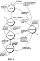
- the computer controlled system has several states, the method of the invention being implemented as a "state" machine or system.
- the machine or system With the occurrence of power on, the machine or system enters the Setup state during which the system stores approximately one minute's worth of both brake pipe and equalizing reservoir pressure data. This data is later used to determine the rate of change of these pressures to determine pressure stability.
- the system enters the Stability state during which operating pressures are determined.
- the EOT unit is commanded to update the operating pressures stored in its microprocessor control circuit. Once the several pressures have been found to be stable, the system goes to the Stability state or a Release state.
- the system makes transitions between the Release state and the Stability state until a predetermined decrease in brake pipe pressure is detected. At this point, the system makes a transition to the Application (service) state. In this state, determinations are made as to whether to transmit brake commands to the EOT unit or to return to one of the Stability or Release states. In any of these states, the system can immediately enter the Emergency state, even if operating pressures have not been established. Once an emergency condition ceases to exist, the system exits from the Emergency state to the Setup state, if setup has not been completed, or to the Release state if setup has been completed.
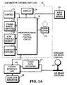
- FIG. 1 there is shown a block diagram of a locomotive control unit (LCU) 12 and an end of train (EOT) unit 14 mechanically linked together by a train (not shown) and communicating by radio transmission.
- the EOT unit 14 is typically mounted on the trailing coupler (not shown) of the last car in the train and is equipped with pressure monitoring and telemetry circuitry.
- a hose is connected between the train's brake pipe and the EOT unit so that the air pressure of the brake pipe at the end of the train can be monitored.
- the LCU 12 includes a microprocessor control circuit 16, a nonvolatile memory 18, which stores the control program for the microprocessor control circuit, and a series of thumb wheel switches 22 through which an operator (e.g., the engineer) stationed at the LCU can manually enter the code number of the EOT unit 14, which code is unique.
- the microprocessor control circuit 16 also has a command switch input 24 and a communication test (COMTEST) switch input 25 and provides outputs to a display 26 and to radio transceiver 28.
- COMPEST communication test
- FIG 1 shows the typical locomotive engineer locomotive air brake control at 32, and the normal air brake pipe 46 which extends the length of the train.
- Existing LCUs are connected to the locomotive's axle drive via an axle drive sensor 30 which provides typically twenty pulses per wheel revolution.
- the EOT unit 14 includes a microprocessor control circuit 34, and a nonvolatile memory 36 in which the control program for the microprocessor control circuit and a unique identifier code of the particular EOT unit 14 are stored.
- the microprocessor control circuit 34 also has inputs from a motion detector 37, a manually activated arming and test switch 38, and a brake pressure responsive transducer 42.
- the microprocessor control circuit 34 generates an output to a brake valve 40 coupled to the brake pipe 46.
- the EOT unit 14 communicates with radio transceiver 28 of the LCU 12 by way of a radio transceiver 44 and associated antennae.
- SIU System Interface Unit
- Figure 1 which Unit interfaces brake pressure values in pipe 46 with microprocessor control circuit 16 so that changes in pressure at the locomotive end of the brake pipe are coupled directly to the microprocessor control circuit 16.
- the System Interface Unit 48 is also connected a brake equalizer reservoir 49.
- the SIU provides electrical signal outputs proportional to sensed brake pipe pressure and equalizer reservoir pressure values directly to the microprocessor control circuit 16.
- the SIU 48 senses and communicates to LCU 12 the arrival of an emergency brake application.
- LCU 12 and SIU 48 function as a unit.
- microprocessor control circuit 16 of the LCU/SIU 48 unit functions may be summarized as follows:
- the EOT microprocessor control circuit 34 functions may be similarly summarized as follows:
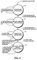
- FIG. 2 of the drawings shows a state diagram of system functions.
- the first state is the Setup procedure 51 the purpose of which is to allow the system to store approximately one minute's worth of data representing both brake pipe 46 and equalizing reservoir 49 pressures. This is needed to determine the rate of change of these pressures to determine stability.
- the system can respond to an emergency, however, because the time frame is only about 0.6 seconds to recognize an emergency.
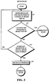
- a measurement is first made in function block 61 of the rate and magnitude of change of the pressure in brake pipe 46 by the control software in memory 18 of microprocessor 16.
- a test is made in decision block 62 to determine if the measured rate of change of brake pipe pressure is greater than say 14 pounds per square inch (psi) in 0.6 seconds. If so, the process of the microprocessor exits to an Emergency state 55 in Figure 2. Otherwise, a test is made in decision block 63 to determine if approximately sixty seconds of brake pipe and equalization reservoir (EqRes) data have been stored in the microprocessor. If not, the process returns back to function block 61 to continue the measurement of data. When sixty seconds of brake pipe and equalization reservoir pressure data have been stored a Setup flag is set to "complete" in function block 64 by microprocessor 16, and the process exits to the Stability state 52 in Figure 2.
- the Stability state 52 monitors the stability of pressure signals. Pressure stability is established for brake pipe 46 if the following conditions are met: (1) the locomotive brake pipe signal (BP_loco) is stable when brake pipe pressure changes less than about 0.3 pounds per square inch per minute (psi/min), (2) an equalizing reservoir signal (Eq_Res) is stable when the pressure in equalizing reservoir 49 changes less than say 0.3 psi/min, and (3) the EOT brake pipe signal (BP_eot) is stable when the EOT brake pipe 46 pressure changes less than say 0.3 psi/three minutes.
- BP_loco is stable when brake pipe pressure changes less than about 0.3 pounds per square inch per minute (psi/min)
- Eq_Res equalizing reservoir signal
- BP_eot is stable when the EOT brake pipe 46 pressure changes less than say 0.3 psi/three minutes.
- Operating pressures are determined in the Stability state 52.
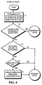
- the flow diagram for this state is shown in Figure 4.
- the process begins by SIU 48 measuring the rate of change of pressure at equalizing reservoir 49(EqRes), brake pipe pressure at the locomotive end of the train, and brake pipe pressure at the EOT (via transducer 42 and microprocessor 34) in function block 71.
- a test is made in decision block 72 to determine if the measured rate of change of brake pipe pressure is greater than say 14 psi in 0.6 seconds. If so, the process exits to the Emergency state 55 in Figure 2. Otherwise, the equalizing reservoir 49 is checked for pressure stability in decision block 73. If the change in reservoir pressure over one minute has been less than 0.3 psi, it is considered stable.
- the pipe pressure at the end of the train is transmitted to the microprocessor 16 in locomotive unit 12 from microprocessor 34 in unit 14 by transceiver's 44 and 30.
- the process of the program of microprocessor 16 exits directly to the Release state 53 in Figure 2. If all three pressures are stable, a check is made in decision block 74 to determine if a Release flag is set by microprocessor 16. If not, the process exits directly to the Release state 53 in Figure 2; otherwise an Update Operating Pressures command is transmitted to the EOT unit 14 as indicated in function block 75, and the reset flag is cleared by the program of microprocessor 16. The system then goes to the Release state 53 in Figure 2.
- the flow diagram of the Release state is shown in Figure 5.
- the process begins by again measuring pressure rate of change and pressure magnitude in equalizing reservoir 49 (Eq_Res) and brake pipe 46 as seen in function block 81. Again, a test is made in decision block 82 to determine if the measured rate of change of brake pipe pressure is greater than say 14 psi in 0.6 seconds. If so, the process exits to the Emergency state 55 in Figure 2. Otherwise, the equalizing reservoir pressure is checked in decision block 83 to determine if there is a pressure decrease greater than say two psi in five seconds. If not, the process goes back to the Stability state 52 in Figure 2. If so, the process goes to the application state 54 in Figure 2, which is the state when brakes are in service.
- Declaring that the system is stable at 52 is not the sole criterion for going to the Release state 53. If the system does not see an emergency (decision block 72), it goes to the Release state. The system makes transitions between the Stability and Release states until either of two conditions occur. Either an emergency is detected or a service application is detected. If brake application is seen with a decrease in pressure of about two psi in five seconds in the equalization reservoir (decision block 83 in Figure 5), the system makes a transition to the Application state 54. In the event that an application is seen, the system first makes a transition to the Application state 54. It then continuously monitors for a release condition (increase of say three psi in ten seconds in equalization reservoir pressure). It also determines the depth (magnitude of the decrease) of the reduction in order to generate brake commands for transmission to the End of Train Unit 14 ( Figure 1).
- the equalizing reservoir pressure signal (Eq_Res) is monitored at Release state 53 for application or release cycles. Whenever the brakes make a transition from the Application to Release states, the LCU 12 will transmit a release command to the EOT unit 14. If the EOT unit is venting the brake pipe at the time the "Brakes Release" command is received, it will cease venting of the brake pipe.
- the LCU 14/SIU 48 combination in Figure 1 establishes operating pressures by monitoring application and release cycles of the brakes.
- the equalizing reservoir pressure signal (Eq_Res) decreasing by say two psi within five seconds indicates that the brakes are applied, causing the system to go to Application state 54.
- the Eq_Res signal increasing by approximately three psi within ten seconds indicates brakes are released, causing the system to go back to Release state 53.
- Stability state 52 where a determination is made of brake pipe stability in release.
- the EOT unit 14 Upon receipt of the "Update Op Pres" command from the LCU 12, the EOT unit 14 accepts the values BP_op and Eq_Res_op and generates BP_eot_fc_lcl, which is the current brake pipe pressure at the EOT unit.
- a Qualify Minimum Application state 91 is entered from Release state 53.
- the system powers on, it cannot determine whether or not the brakes are applied or released.
- the system assumes the brakes to be released for purposes of establishing operating pressures.
- a "Min Appl" command for microprocessor 16 will cause the EOT unit 14 to make a reduction relative to the EOT brake pipe 46 pressure such that the system of the invention must now verify that the brakes are in fact in release before performing a minimum brake application (Min Appl).
- the LCU 12/SIU 48 generate minimum application and service brake commands only after the operating pressures have been established at the LCU/SIU and the EOT unit 14. Simultaneous minimum application and service brake commands can be issued only after the operating pressures have been established at the LCU/SIU and the EOT unit 14. A minimum application by the EOT unit will only be performed when brake pipe 46 is fully charged. The EOT unit 14 will not make a minimum application if the pneumatic reduction on pipe 46 has reached the EOT unit before the electronic brake command arrives via transceiver 44.
- the logic of the Qualify Minimum Application state 91 is shown in the flow diagram of Figure 7, to which reference is now made.
- a measurement is made of the rate and magnitude of change in equalization reservoir 49 (EqRes) and brake pipe 46 pressures in function block 101.
- a test is made in decision block 102 to determine if the measured rate of change of brake pipe pressure is greater than approximately 14 pounds per square inch (psi) in say 0.6 seconds. If so, the process exits to the Emergency state 55 in Figure 2. Otherwise, the pressure in equalizing reservoir 49 is checked in decision block 103 to determine if the pressure has increased more than say three psi in ten seconds. If so, the release flag is set in function block 104, and the system goes to the Release state 53 in Figure 2.
- decision block 105 determines if the Eq_Res signal has decreased by at least two psi below the value of Eq-Res-Op when the brakes are released. If not, the process loops back to function block 101 to continue the measurement of pressure change. If so, a check is made in decision block 106 to determine if the reset flag is set. If it is, the process loops back to function block 101; otherwise, a check is made in decision block 107 to determine if the minimum flag is set. If it is not set, the command "Min Application Brk" is transmitted to the EOT unit 14 by the LCU 12 in function block 108. If it is set, the process goes to "Quality service application" 92 ( Figure 6).
- the EOT unit decreases brake pipe pressure according to a valve control algorithm located in memory 36.
- the Qualify Service Applications state 92 ( Figure 6) is entered, as seen Figure 7.
- the flow diagram of the Qualify Service Applications state is shown in Figure 8.
- the process measures the rate and magnitude of change of the equalization reservoir 49 and brake pipe 46 pressures in function block 111.
- a test is made in decision block 112 to determine if the measured rate of change of brake pipe pressure is greater than approximately 14 psi in 0.6 seconds. If so, the process exits to the Emergency state 55 in Figure 2. Otherwise, the equalizing reservoir pressure is checked in decision block 113. If an increase in pressure is greater than say 3 psi in ten seconds, the release flag is set in function block 114, and the system reverts to the Release state 53 in Figure 2.
- the equalizing reservoir pressure is checked in decision block 115 to determine if there has been a decrease in pressure of at least 7 psi from the operating pressure. If so, brake commands are sent to the EOT 14 in function block 116, and the system goes to the Stability in Application state 93 in Figure 6. Otherwise, the process loops back to function block 111 to continue measuring rate and magnitude of pressure changes in equalization reservoir 49 and brake pipe 46.
- the stability in application procedure 93 in Figure 6 is entered upon the signal Eq_Res decreasing at least say 7 psi below the value of Eq_Res_op when the brakes are applied.
- the LCU 12 /SIU 48 generate a "Service Brk” command. This command includes the current pressure in equalization reservoir 49.
- the "Service Brk” command is transmitted every two seconds while the Eq_Res signal is decreasing until it stabilizes. The procedure is shown in Figure 9, to which reference is now made.
- the rate and magnitude of change in equalization reservoir 49 and brake pipe 46 pressures are measured in function block 121.
- a test is made in decision block 122 to determine if the measured rate of change of brake pipe pressure is greater than approximately 14 psi in 0.6 seconds. If so, the process exits to the Emergency state 55 in Figure 2. Otherwise, equalizing reservoir pressure is checked in decision block 125.
- the Eq_Res signal is declared stable in application in function block 126 when it decreases less than say 0.3 psi in fifteen seconds and there is an increase in pressure of no more than say 0.3 psi in fifteen seconds. At this point, the system goes to the Qualify Deeper Service Application state 94 in Figure 6.
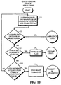
- the Qualify Deeper Service Application state is illustrated in the flow diagram of Figure 10.
- the rate and magnitude of change in the equalization reservoir and brake pipe pressures are measured in function block 131.
- a test is made in decision block 132 to determine if the measured rate of change of brake pipe pressure is greater than approximately 14 psi in 0.6 seconds. If so, the process exits to the Emergency state 55 in Figure 2. Otherwise, the equalizing reservoir pressure is checked in decision block 133. If the change in pressure is greater than say three psi in ten seconds, the release flag is set in function box 134, and the system reverts to the Release state 53 in Figure 2. Otherwise, the equalizing reservoir pressure is checked in decision block 135.
- brake commands are transmitted to the EOT 14 in function block 136, and the system reverts to the Stability in Application state 93 shown in Figure 6; otherwise, the process loops back to function block 131 to continue measurement of rate and magnitude of pressure changes in equalization reservoir 49 and brake pipe 46.
- the microprocessor 34 of EOT unit 14 Upon receiving a "Service Brk" command from the LCU 12, the microprocessor 34 of EOT unit 14 calculates the target brake pipe reduction using an error valve in the accuracy of transducer 42 and the current pressure valve contained in the service brake command. Microprocessor 34 then orders the venting of brake pipe 46 to the target brake pipe reduction.
- the "Brakes Released” command is transmitted to the EOT unit 14 by microprocessor 16.
- the EOT unit ends control of the brake pipe by going to the "release” state of the valve control effected at 40 ( Figure 1).
- a delta or minimum equalizing reservoir braking function permits EOT unit 14 to become effective for small incremental reductions in brake pipe pressure.
- the EOT unit makes a proportional decrease in brake pipe pressure corresponding to the decrease in equalizing reservoir 49 pressure at the locomotive end as sensed by SIU 48.
- del_Eq_Res braking function must be avoided. The first is when a false gradient exists in the train. The second is if the electronic brake command from transceiver 28 is delayed such that the locomotive controlled pneumatic reduction influences brake pipe 46 pressure at the EOT unit 14 before the electronic command is received via transceiver 44.
- the SIU 48 synchronizes the EOT unit 14 via the LCU 12 upon updating operating pressures, and it resynchronizes the EOT unit if the time stamps differ substantially.
- the SIU is responsible for maintaining synchronization.
- the command to "synchronize” is, however, transmitted by the LCU 12 from transceiver 28 to transceiver 44 at the EOT unit 14.
- the "Sync" command includes the SIU time stamp which can be 0 to 60 seconds. Upon receipt of the "Sync" command, the EOT unit 14 synchronizes itself to the SIU supplied time stamp.
- a simultaneous minimum brake application provided by EOT unit 14 is only performed when brake pipe 46 is fully charged.
- the EOT unit 14 responds to the "Min Appl Brk" command from LCU 12 by making a relative reduction in brake pipe pressure.
- the EOT unit 14 is programmed to refuse a minimum brake application command if pneumatic reduction has reached the EOT unit 14 via brake pipe 46 before the electronic brake command from transceiver 28.
- An Eq_Res signal indicates a change in the brake state from released to applied. Upon the occurrence of this change the value of the false gradient that occurs at the initiation of this application is saved
- a brake application number is generated and incremented in memory 18 of microprocessor 16
- a sub-application number is generated and reset in memory 18, and a Eq_Res_blw_FG flag is cleared in microprocessor 16.
- the "Min Application Brk" command is generated and transmitted to EOT unit 14 if all of the following conditions are true:
- microprocessor 34 of EOT unit 14 determines if a "Min Application Brk” command has already been received. If so, EOT unit 14 will not perform the minimum brake application command. Otherwise, EOT unit 14 looks up the value of BP_eot at the time "Min Application Brk” command was generated. If the current BP_eot value is greater than or equal to approximately four psi below the BP-eot value at the time the "Min Application Brk" command was generated, then the EOT will not make the minimum brake application; otherwise the EOT application is performed according to the above calculated target brake pipe reduction using a transducer 42 error value and the current pressure value in the min appl. brk. command.
- the LCU 12/ SIU 48 indicates a service brake reduction to the EOT unit 14 by transmitting either the gauge pressure of equalization reservoir 49 or a change in equalization reservoir pressure.
- the equalization reservoir gage pressure provides an unambiguous indication of where the pressure of brake pipe 46 at the EOT is going to end up, but it is not suitable for small incremental reductions.
- a change in equalization reservoir pressure is efficient for small incremental reductions but requires that there be no false gradient.
- Service brake commands utilizing pressure values in equalizing reservoir 49 are used until equalization reservoir pressure reduction has stabilized at a level greater than or equal to that of a false gradient. After this point, changing (delta) equalizing reservoir pressure values are transmitted to the EOT unit 14 from LCU 12.
- the "Service Brk/del_Eq_Res" command is transmitted to the EOT unit 14 if the Eq_Res_blw_FG flag is set in microprocessor 16 and when the following conditions are true:
- the EOT unit 14 upon receipt of the "Service Brk/Eq_Res_cur" command from the LCU 12 calculates the target brake pipe reduction using a maximum error value in the accuracy of transducer 42 and the pressure value contained in the service brake command, and vents the brake pipe to the BP_tar using brake valve 40.
- microprocessor 34 of EOT unit 14 Upon receipt of the "Service Brk/del_Eq_Res" command with a new sub-application number, microprocessor 34 of EOT unit 14 looks up values of BP_eot, BP_tar and whether or not the EOT unit was in control of brake pipe 46 when this brake command was generated. If the EOT unit was controlling the brake pipe at the time the command was generated by the microprocessor the variable BP_eot_sel is set equal to the BP_tar at the time the command was generated. If the EOT unit was not controlling the brake pipe when the command was generated, the variable BP_eot_sel is set equal to BP_eot by microprocessor 34 at the time the command was generated by microprocessor 16.
- microprocessor 34 Upon updating BP_eot_sel, microprocessor 34 calculates BP_tar using again transducer 42 error and the pressure valve in the service brake command, and controls brake pipe pressure accordingly.
- the system monitors the EOT brake pipe pressure for an increase in the fully charged pressure due to decreased leakage. While the brakes are applied, the Eq_Res, Bp_loco and BP_eot signals are monitored. If all three of the pressures change less than say 0.3 psi over a ten second period, the current pressures are saved in memories 18 and 36 as the stable pressures for gradient monitoring (Eq_Res_grad_mon, BP_grad_mon, and BP_eot_grad_mon, respectively) and the "Get stable pressure for gradient monitor" command is transmitted to the EOT unit 14. The value BP_eot_fc is saved as BP_eot_fc_rel in memory 18 of microprocessor 16. The LCU 12/SIU 48 then enables monitoring of the gradient during brake application.
- the signals BP_loco and Eq_Res are monitored by microprocessor 16 to ensure they are within about ⁇ 0.3 psi of their stable pressures for gradient monitoring. If they are stable, the current EOT brake pipe pressure (BP_eot) is compared to the BP_eot stable pressure for gradient monitoring by the microprocessors. If this difference is greater than or equal to say one psi, the "Adjust BP_eot_fc for decreasing gradient" command is transmitted from LCU 12 to EOT unit 14, and the local value of BP_eot_fc is adjusted and repeated using the difference between BP_eot_cur and BP_eot stable pressure in application if increasing by at least one psi.
- microprocessor 34 of the EOT unit 14 Upon receipt of the "Get stable pressure for gradient monitor" command, the microprocessor 34 of the EOT unit 14 saves the current value of BP_eot as BP_eot_grad_mon. In addition, BP_eot fc is saved as BP_eot_fc_rel. Upon receipt of the "Adjust BP_eot_fc for decreasing gradient" command, microprocessor 34 of the EOT unit 14 recalculates BP_eot_fc using the relationship of BP_eot_cur and BP_eot stable pressure.
- the emergency brake command is transmitted with or without operating pressure information being established.
- the LCU 12/SIU 48 Upon brake pipe pressure at the locomotive end decreasing say at least 14 psi within 0.6 seconds, the LCU 12/SIU 48 transmit an "Emergency Brk" command to the EOT unit 14, and the emergency procedure 55 ( Figure 2) is entered.
- the "Emergency Brk” command is generated for a particular application, generation of the "Service Brk” commands are disabled by microprocessor 16 until a release is detected by the signal Eq_Res increasing approximately three psi within ten seconds.
- microprocessor 34 of the EOT unit 14 vents the brake pipe locally.
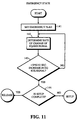
- the Emergency state logic of the invention is shown in Figure 11.
- the system Upon entering the Emergency state, the system sets an emergency flag in function block 141.
- the rate of change in pressure in of the equalization reservoir 49 is measured in function block 142. If the rate of change measured at 142 is not less than three psi in approximately ten seconds, the process returns to 142 for another measurement. If it is less than three psi in ten seconds, the program moves to decision block 144 to determine if the setup process 51 in Figure 2 is complete. If not, the process exits to Setup process 51. If so, the process exits to the Release state 53 in Figure 2.
- Figure 12 is a flow diagram of the logic of the software in memory 36 for a EOT unit pneumatic self-test using microprocessor 34.
- the process of the test is initiated by depressing a test button on the microprocessor, typically when EOT 14 is first installed on a coupler mount (of a car coupler), or performing a self-test initiated by the SIU 48 at other times.
- the value of the EOT self test brake pipe pressure (BP EOT.SLF_TST ) is set equal to the service brake pressure (BP EOT.SVR ) as seen in function block 151.
- the release service valve of the brake system is closed and a self-test timer is initialized for about 30 seconds.
- the initialization phase brings the logic of the software in memory 36 to state 0.
- a test is made at decision block 152 to determine if the value BP EOT.SVR is less than BP EOT.SLF_TST reduced by say three eighths. If so, the result of the self-test is FAIL which is output at block 153. If not, a further test is made in decision block 152. When the self-test timer has timed out, the software of memory 36 is at a state 1.
- the next step is to open the release service valve for say ten seconds, as indicated in function block 155.
- BP EOT.SLF_TST is set equal to BP EOT.SVP
- the release service valve is closed, and the supply/exhaust service valve of the brake system is opened.
- the self-test timer is initialized to say ten seconds, to bring the software of memory 36 to state 2.
- a test is then made in decision block 157 to determine if the self-test timer has timed out. If so, the result of the self-test is FAIL which is output to block 153. If not, a further test is made in decision block 158 to determine if BP EOT.SVR is less than BP EOT.SLF_TST reduced by say three eighths. If not, a return is made to decision block 77. If so, the software of 36 is brought to a state 3.
- the result of the software of 36 reaching state 3 is that the self-test result is PASS in block 159.
- the results of the self-test, whether FAIL in block 153 or PASS in block 159 are displayed on monitor 26 in the locomotive and then, in function block 160 the release service valve is opened and the supply/exhaust service valve is closed. This ends the self-test.
Landscapes
- Engineering & Computer Science (AREA)
- Transportation (AREA)
- Mechanical Engineering (AREA)
- Braking Systems And Boosters (AREA)
Applications Claiming Priority (2)
| Application Number | Priority Date | Filing Date | Title |
|---|---|---|---|
| US38175 | 1993-03-29 | ||
| US09/038,175 US6126247A (en) | 1998-03-10 | 1998-03-10 | Computer control of railroad train brake system operation |
Publications (2)
| Publication Number | Publication Date |
|---|---|
| EP0941904A2 true EP0941904A2 (de) | 1999-09-15 |
| EP0941904A3 EP0941904A3 (de) | 2002-04-17 |
Family
ID=21898481
Family Applications (1)
| Application Number | Title | Priority Date | Filing Date |
|---|---|---|---|
| EP98119185A Withdrawn EP0941904A3 (de) | 1998-03-10 | 1998-10-12 | Computersteuerung vom Betrieb einer Schienenfahrzeug-Bremsanlage |
Country Status (6)
| Country | Link |
|---|---|
| US (1) | US6126247A (de) |
| EP (1) | EP0941904A3 (de) |
| AU (1) | AU741991B2 (de) |
| BR (1) | BR9900279A (de) |
| CA (1) | CA2248969C (de) |
| ZA (1) | ZA989103B (de) |
Cited By (2)
| Publication number | Priority date | Publication date | Assignee | Title |
|---|---|---|---|---|
| RU2243117C1 (ru) * | 2003-03-31 | 2004-12-27 | Государственное унитарное предприятие "Уральское отделение Всероссийского научно-исследовательского института железнодорожного транспорта" | Электропневматический тормоз моторвагонного подвижного состава |
| EP1790544A1 (de) | 2005-11-28 | 2007-05-30 | Freinrail Systèmes Ferroviaires SA | Verbesserungen von am Zugende montierten Einheiten und entsprechende Verwendung |
Families Citing this family (29)
| Publication number | Priority date | Publication date | Assignee | Title |
|---|---|---|---|---|
| US6997418B1 (en) | 1997-11-05 | 2006-02-14 | Ge-Harris Raliway Electronics, L.L.C. | Methods and apparatus for testing a train control system |
| US20030040790A1 (en) | 1998-04-15 | 2003-02-27 | Furst Joseph G. | Stent coating |
| US8070796B2 (en) | 1998-07-27 | 2011-12-06 | Icon Interventional Systems, Inc. | Thrombosis inhibiting graft |
| US7967855B2 (en) | 1998-07-27 | 2011-06-28 | Icon Interventional Systems, Inc. | Coated medical device |
| US6443538B1 (en) | 2000-12-29 | 2002-09-03 | Ge Harris Railway Electronics, Llc | Feed valve and reference pressure enhancement |
| US9151232B2 (en) | 2001-03-27 | 2015-10-06 | General Electric Company | Control system and method |
| US7302895B2 (en) * | 2002-02-28 | 2007-12-04 | General Electric Company | Configurable locomotive |
| US6650993B2 (en) * | 2001-06-04 | 2003-11-18 | General Electric Company | Automatic start/stop system and method for locomotive engines |
| US6671591B2 (en) | 2001-06-04 | 2003-12-30 | General Electric Company | System and method for monitoring locomotive operation |
| US6799132B2 (en) * | 2003-01-08 | 2004-09-28 | Westinghouse Air Brake Technologies Corporation | Smart resolution valve pressure control |
| US6820944B2 (en) * | 2003-01-08 | 2004-11-23 | Westinghouse Air Brake Technologies Corporation | Digital multi-point electronic load weigh system |
| US7715956B2 (en) * | 2004-02-27 | 2010-05-11 | General Electric Company | Method and apparatus for swapping lead and remote locomotives in a distributed power railroad train |
| US8781671B2 (en) * | 2005-06-09 | 2014-07-15 | New York Air Brake Corporation | On-board brake system diagnostic and reporting system |
| US7915342B2 (en) * | 2005-11-28 | 2011-03-29 | Fina Techology, Inc. | Breathable films |
| US7455370B2 (en) * | 2005-11-29 | 2008-11-25 | New York Air Brake Corporation | Brake pipe control system with remote radio car |
| US20070247000A1 (en) * | 2006-04-21 | 2007-10-25 | Fugiel Robert V | Portable control device for wireless communication with air brake line airflow manipulating device |
| US8000873B2 (en) * | 2008-05-12 | 2011-08-16 | Wabtec Holding Corp. | Braking system |
| US8190313B2 (en) * | 2008-10-10 | 2012-05-29 | General Electric Company | System and method for reducing a penalty period for a distributed power train |
| AU2010310546A1 (en) * | 2009-10-22 | 2012-05-17 | Wabtec Holding Corp. | Brake pipe charge monitor system and method |
| US9403517B2 (en) | 2010-12-22 | 2016-08-02 | Wabtec Holding Corp. | System and method for determining air propagation data in a braking arrangement of a train |
| US8922385B2 (en) * | 2013-01-25 | 2014-12-30 | Electro-Motive Diesel, Inc. | Vehicle coupling fault detecting system |
| US9616876B2 (en) | 2015-06-29 | 2017-04-11 | Westinghouse Air Brake Technologies Corporation | Verification system and method for an end-of-train unit of a train and an improved end-of-train unit for a train |
| US20180072296A1 (en) * | 2016-09-12 | 2018-03-15 | Klaus G. Buchberger | System and method for wireless digital air brake testing |
| US11027756B2 (en) | 2017-11-16 | 2021-06-08 | Westinghouse Air Brake Technologies Corporation | ECP overlay system for UIC-type distributor valve |
| US11014585B2 (en) | 2017-11-16 | 2021-05-25 | Westinghouse Air Brake Technologies Corporation | ECP overlay system for W-type triple valve |
| US10994756B2 (en) | 2017-11-16 | 2021-05-04 | Westinghouse Air Brake Technologies Corporation | Electronically controlled brake overlay system for distributor valve |
| DE102019108066A1 (de) * | 2019-03-28 | 2020-10-01 | Knorr-Bremse Systeme für Schienenfahrzeuge GmbH | System zum Bereitstellen und/oder Überwachen von Betriebsdaten einer Druckluftversorgung, Druckluftversorgung und Verfahren zum Bereitstellen von Betriebsdaten und/oder zum Überwachen der Funktionsfähigkeit einer Druckluftversorgung |
| US12600339B2 (en) | 2022-10-14 | 2026-04-14 | Zf Cv Systems Global Gmbh | Leak detection for pneumatic braking systems |
| DE102022133263A1 (de) | 2022-12-14 | 2024-06-20 | Zf Cv Systems Global Gmbh | Verfahren zur Steuerung eines Bremssystems sowie Brems-Steuergerät und Fahrzeug |
Citations (2)
| Publication number | Priority date | Publication date | Assignee | Title |
|---|---|---|---|---|
| US4056286A (en) | 1976-06-08 | 1977-11-01 | Westinghouse Air Brake Company | Remote control brake system for a railway train |
| US5374015A (en) | 1992-12-01 | 1994-12-20 | Pulse Electronics, Inc. | Railroad telemetry and control systems |
Family Cites Families (10)
| Publication number | Priority date | Publication date | Assignee | Title |
|---|---|---|---|---|
| JPS59192660A (ja) * | 1983-04-15 | 1984-11-01 | Mitsubishi Heavy Ind Ltd | 列車のブレ−キ装置 |
| US4553723A (en) * | 1983-09-15 | 1985-11-19 | Harris Corporation | Railroad air brake system |
| US4859000A (en) * | 1988-08-15 | 1989-08-22 | Harris Corp. | Adaptive air brake control system |
| US5172316A (en) * | 1989-12-08 | 1992-12-15 | New York Air Brake | Computer controlled railway brake equipment |
| US5551765A (en) * | 1995-06-22 | 1996-09-03 | Westinghouse Air Brake Company | Electric brake control system and method for railroad car |
| US5747685A (en) * | 1995-07-20 | 1998-05-05 | Westinghouse Air Brake Company | Automated terminal test procedure |
| US5924774A (en) * | 1995-11-30 | 1999-07-20 | Zeftron, Inc. | Electronic pneumatic brake system |
| US5833325A (en) * | 1996-02-06 | 1998-11-10 | Westinghouse Air Brake Company | Freight brake control using train net braking ratio |
| US5681015A (en) * | 1996-12-20 | 1997-10-28 | Westinghouse Air Brake Company | Radio-based electro-pneumatic control communications system |
| US5941280A (en) * | 1997-03-11 | 1999-08-24 | Westinghouse Air Brake Company | Pneumatically driven train brake pipe pressure exhaust valve |
-
1998
- 1998-03-10 US US09/038,175 patent/US6126247A/en not_active Expired - Lifetime
- 1998-09-28 CA CA002248969A patent/CA2248969C/en not_active Expired - Lifetime
- 1998-09-30 AU AU87118/98A patent/AU741991B2/en not_active Expired
- 1998-10-06 ZA ZA9809103A patent/ZA989103B/xx unknown
- 1998-10-12 EP EP98119185A patent/EP0941904A3/de not_active Withdrawn
-
1999
- 1999-02-01 BR BR9900279-5A patent/BR9900279A/pt not_active Application Discontinuation
Patent Citations (2)
| Publication number | Priority date | Publication date | Assignee | Title |
|---|---|---|---|---|
| US4056286A (en) | 1976-06-08 | 1977-11-01 | Westinghouse Air Brake Company | Remote control brake system for a railway train |
| US5374015A (en) | 1992-12-01 | 1994-12-20 | Pulse Electronics, Inc. | Railroad telemetry and control systems |
Cited By (3)
| Publication number | Priority date | Publication date | Assignee | Title |
|---|---|---|---|---|
| RU2243117C1 (ru) * | 2003-03-31 | 2004-12-27 | Государственное унитарное предприятие "Уральское отделение Всероссийского научно-исследовательского института железнодорожного транспорта" | Электропневматический тормоз моторвагонного подвижного состава |
| EP1790544A1 (de) | 2005-11-28 | 2007-05-30 | Freinrail Systèmes Ferroviaires SA | Verbesserungen von am Zugende montierten Einheiten und entsprechende Verwendung |
| FR2893899A1 (fr) * | 2005-11-28 | 2007-06-01 | Freinrail Systemes Ferroviaire | Perfectionnements aux equipements montes a l'arriere d'un train et utilisations associees |
Also Published As
| Publication number | Publication date |
|---|---|
| AU741991B2 (en) | 2001-12-13 |
| EP0941904A3 (de) | 2002-04-17 |
| CA2248969C (en) | 2004-12-07 |
| US6126247A (en) | 2000-10-03 |
| BR9900279A (pt) | 2000-01-04 |
| CA2248969A1 (en) | 1999-09-10 |
| AU8711898A (en) | 1999-09-23 |
| ZA989103B (en) | 2000-02-10 |
Similar Documents
| Publication | Publication Date | Title |
|---|---|---|
| US6126247A (en) | Computer control of railroad train brake system operation | |
| US5813635A (en) | Train separation detection | |
| US5039038A (en) | Railroad communication system | |
| US4553723A (en) | Railroad air brake system | |
| US5738311A (en) | Distributed power train separation detection | |
| US6114974A (en) | Method and apparatus for determining railcar order in a train | |
| US5016840A (en) | Method to authorize a head of train unit to transmit emergency commands to its associated rear unit | |
| US5924774A (en) | Electronic pneumatic brake system | |
| US6401015B1 (en) | Distributed power and electronic air brake control system for a train and associated methods | |
| AU741050C (en) | Railway brake system including enhanced pneumatic brake signal detection and associated methods | |
| EP0829415B1 (de) | Automatische Wagenreihungsbestimmung für Zug mit Orientierung eines Waggons | |
| US5752748A (en) | Electronic brake system with back-up control during central module failure | |
| US5507457A (en) | Train integrity detection system | |
| MXPA00008247A (es) | Probador de campo bidireccional para dispositivo de eot. | |
| US5966674A (en) | Flow signal filter | |
| EP1119483B1 (de) | Zugintegritätsüberwachungsvorrichtung | |
| WO1990001440A1 (en) | Adaptive air brake control system | |
| US5966084A (en) | Automatic train serialization with car orientation | |
| US5740029A (en) | Software algorithm providing dynamic configuration of dead band control criteria within a micro based real time process control environment | |
| MXPA99002338A (es) | Control por computadora de la operacion de unsistema de frenos de un tren de ferrocarril | |
| EP1226057A1 (de) | Betriebsbremssystem ohne radiokommunikation für das zugende eines zuges | |
| AU736856B2 (en) | Automatic train serialization with car orientation | |
| AU5355899A (en) | Electronic pneumatic brake system |
Legal Events
| Date | Code | Title | Description |
|---|---|---|---|
| PUAI | Public reference made under article 153(3) epc to a published international application that has entered the european phase |
Free format text: ORIGINAL CODE: 0009012 |
|
| AK | Designated contracting states |
Kind code of ref document: A2 Designated state(s): AT BE CH CY DE DK ES FI FR GB GR IE IT LI LU MC NL PT SE |
|
| AX | Request for extension of the european patent |
Free format text: AL;LT;LV;MK;RO;SI |
|
| PUAL | Search report despatched |
Free format text: ORIGINAL CODE: 0009013 |
|
| PUAF | Information related to the publication of a search report (a3 document) modified or deleted |
Free format text: ORIGINAL CODE: 0009199SEPU |
|
| AK | Designated contracting states |
Kind code of ref document: A3 Designated state(s): AT BE CH CY DE DK ES FI FR GB GR IE IT LI LU MC NL PT SE |
|
| AX | Request for extension of the european patent |
Free format text: AL;LT;LV;MK;RO;SI |
|
| RIC1 | Information provided on ipc code assigned before grant |
Free format text: 7B 60T 13/66 A, 7B 60T 17/22 B |
|
| D17D | Deferred search report published (deleted) | ||
| PUAL | Search report despatched |
Free format text: ORIGINAL CODE: 0009013 |
|
| AX | Request for extension of the european patent |
Free format text: AL;LT;LV;MK;RO;SI |
|
| AKX | Designation fees paid | ||
| REG | Reference to a national code |
Ref country code: DE Ref legal event code: 8566 |
|
| STAA | Information on the status of an ep patent application or granted ep patent |
Free format text: STATUS: THE APPLICATION IS DEEMED TO BE WITHDRAWN |
|
| 18D | Application deemed to be withdrawn |
Effective date: 20030501 |