EP0941651B1 - Wickelvorrichtung einer Presse - Google Patents
Wickelvorrichtung einer Presse Download PDFInfo
- Publication number
- EP0941651B1 EP0941651B1 EP98123163A EP98123163A EP0941651B1 EP 0941651 B1 EP0941651 B1 EP 0941651B1 EP 98123163 A EP98123163 A EP 98123163A EP 98123163 A EP98123163 A EP 98123163A EP 0941651 B1 EP0941651 B1 EP 0941651B1
- Authority
- EP
- European Patent Office
- Prior art keywords
- roll
- roller
- feed
- wrapping device
- bale
- Prior art date
- Legal status (The legal status is an assumption and is not a legal conclusion. Google has not performed a legal analysis and makes no representation as to the accuracy of the status listed.)
- Expired - Lifetime
Links
- 239000000463 material Substances 0.000 claims description 60
- 239000011248 coating agent Substances 0.000 claims 1
- 238000000576 coating method Methods 0.000 claims 1
- 238000004804 winding Methods 0.000 description 7
- 238000004146 energy storage Methods 0.000 description 3
- 230000033001 locomotion Effects 0.000 description 3
- 230000000694 effects Effects 0.000 description 2
- 239000002184 metal Substances 0.000 description 2
- 230000005540 biological transmission Effects 0.000 description 1
- 230000015572 biosynthetic process Effects 0.000 description 1
- 230000001419 dependent effect Effects 0.000 description 1
- 238000001514 detection method Methods 0.000 description 1
- 238000011161 development Methods 0.000 description 1
- 230000018109 developmental process Effects 0.000 description 1
- 230000026058 directional locomotion Effects 0.000 description 1
- 230000002093 peripheral effect Effects 0.000 description 1
- 239000007858 starting material Substances 0.000 description 1
- 210000001364 upper extremity Anatomy 0.000 description 1
Images
Classifications
-
- A—HUMAN NECESSITIES
- A01—AGRICULTURE; FORESTRY; ANIMAL HUSBANDRY; HUNTING; TRAPPING; FISHING
- A01F—PROCESSING OF HARVESTED PRODUCE; HAY OR STRAW PRESSES; DEVICES FOR STORING AGRICULTURAL OR HORTICULTURAL PRODUCE
- A01F15/00—Baling presses for straw, hay or the like
- A01F15/07—Rotobalers, i.e. machines for forming cylindrical bales by winding and pressing
- A01F15/071—Wrapping devices
- A01F15/0715—Wrapping the bale in the press chamber before opening said chamber
-
- A—HUMAN NECESSITIES
- A01—AGRICULTURE; FORESTRY; ANIMAL HUSBANDRY; HUNTING; TRAPPING; FISHING
- A01F—PROCESSING OF HARVESTED PRODUCE; HAY OR STRAW PRESSES; DEVICES FOR STORING AGRICULTURAL OR HORTICULTURAL PRODUCE
- A01F15/00—Baling presses for straw, hay or the like
- A01F15/07—Rotobalers, i.e. machines for forming cylindrical bales by winding and pressing
- A01F15/071—Wrapping devices
- A01F15/0715—Wrapping the bale in the press chamber before opening said chamber
- A01F2015/072—Braking means for the film roll in balers which wrap the bale before opening the pressing chamber in order to stretch the film while wrapping
Definitions
- the invention relates to a winding device of a press at least one rotatably drivable feed roller for Transporting a sheet material from one Roll of material to a bale forming chamber.
- US-A-5,181,368 discloses a round baler with a Net binding device, which is attached to the back.
- the net binding or wrapping device has a housing in which a net roll is rotatably mounted on a floor.
- a pair of feed rollers are provided below the floor, pull the material from the net roll and take it to a bale forming chamber respectively.
- In the area of the peripheral surface of the Net rolls are friction elements on the floor and walls provided that always for sufficient tension of the Between the net roll and the feed rollers.
- the roll of material can be used with both Network as well as wrapped with film or the like.
- a Feed roll is sufficient if the material due to its Pressure angle and / or its tension sufficiently safe is taken from the single feed roller.
- the material can passed between them and securely grasped. If necessary, the gap between them can be narrowed or be enlarged.
- the pressing force of the material roll on the feed roller can either constant or constant by means of a tensioning device but at least be kept to a minimum.
- a spread of the material and thus a uniform Funding is provided through the use of a leadership role, e.g. B. achieved with spiral pads.
- the tension of the Material is kept at a high level in that the Material is redirected several times.
- An additional tension is built up in that the material at a point of the roll of material is withdrawn from its point of contact is spaced from the feed roller, but again is passed through the area between the two.
- the roll of material is thus almost exclusive storage on the feed roller.
- a high tension can also be achieved with low wrap angles can be achieved if at least the authoritative leadership role with a high friction surface, especially with rubber, is coated.
- a slim design of the winding device and sufficient large wrap angle is achieved when the feed rollers are arranged one above the other and thus also a material course with at least one big redirection if the material is not down, but essentially to be released laterally.
- the frictional force between the material roll and the feed roll is not only guaranteed by the pressure on the feed roller, but it can also be done by your own Weight if this is perfect or in any case is essentially shifted to the feed roller.
- the material can be used Inserting a new roll of material easier become.
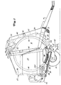
- a press 10 of the large type manufactures cylindrical bales and generally as one large round baler is called.
- the press 10 contains a frame 12 carried by a pair of bottom wheels 14 becomes.
- a drawbar 16 is attached to the frame 12 and trained to be connected to an agricultural tractor can be.
- a pair in the cross direction a distance side walls 18 facing one another is with the frame 12 connected and has rear upright end portions.
- Bale discharge gate 20 with opposing side walls As with 24, 22 can be swiveled vertically at the top rear places of the side walls 18 attached, the Sidewalls 22 have front end portions against the strike rear end portions of side walls 18 when the bale outlet gate 20 in a lower closed Position as shown.
- the pair of side walls 18 and 22 take each other opposite end portions of a plurality of support rollers for the straps to form bales that are close to the Outside of the side walls. If you start at one lower center of the side walls 18 and one drives counterclockwise, then there are one driven roller 26, a lower front roller 28, a front intermediate roller 30, an upper front roller 32 and one upper rear roller 34 provided; and if you're from one upper rear position of the side walls 22 of the Bale unloading gate 20 from further counterclockwise moves, then there is an upper rear roller 36, a lower rear roller 38 and a lower front roller 40 mounted.
- a plurality of endless belts 42 to form one Bale is provided between the pair of side walls 18 and 22 and carried side by side by the various rollers 26.
- straps 42 which are the lower front Skip roll 28
- the straps 42 are formed so that they successively the rollers 26, 28, 30, 32, 36, 38, 40 and 34 act upon.
- a front run 44 of straps 42 extends from the driven roller 26 up to the roller 34.
- a rear run 46 extends in the same way Belt 42 from the lower front roller 40 of the bale unloading gate 20 from up to the roll 34.
- Front and rear pulleys 52 and 54 which are a short distance to each other are between rear end regions of a pair of rearwardly extending tension arms 48 which at 50 vertically swiveling at half height are attached to the front side walls 18, wherein dreams 44 and 46 with side walls 18 and 22 cooperate to form an expandable bale forming chamber 56 form the top of the pulleys 52 and 54th is closed and here in a considerable state Expansion and with a bale 58 shows.
- the Bale forming chamber 56 is empty, the front and converge the rear run 44 or 46 of the straps 42 from the Drive roller 26 and the lower front roller 40 of the Bale unloading gate 20 up and close together between the rollers 52 and 54, the strand 44 touches a rear surface of the front roller 52 and where the run 46 is the front surface of the rear Roller 54 touches so that the bale forming chamber 56 from the Seen from the side takes a wedge shape.
- the bottom of the Bale formation chamber 56 is provided with a good inlet 60, which is between the driven roller 26 and the lower front roller of the bale discharge gate 20 extends.
- the Harvested crop is fed into the crop inlet 60 by means of a pick-up 62 introduced to a bale, such as bale 58, to be rolled up due to the effect of front and rear dreams 44 and 46 of straps 42, which are each driven so that they become the Move inlet 60 to and from it, and initially also from a starter roller 64 that is near the driven Roller 26 is rotatably received in the side walls 18 and in the same direction as this is driven so that it Strips the crop from the front run 44 of the straps 42 is taken down.
- a pick-up 62 introduced to a bale, such as bale 58, to be rolled up due to the effect of front and rear dreams 44 and 46 of straps 42, which are each driven so that they become the Move inlet 60 to and from it, and initially also from a starter roller 64 that is near the driven Roller 26 is rotatably received in the side walls 18 and in the same direction as this is driven so that it Strips the crop from the front run 44 of the straps 42 is taken down.
- bale forming chamber 56 yields up to the predetermined size shown, against the force, which is introduced into the belt 42 by a tensioning system, that the pair of tension arms 48 together with a pair does not shown tension springs and a pair of not shown Includes hydraulic cylinder that between the side walls 18th and the tension arms 48 are inserted one up directional movement of the tension arms 48 in a well known manner Way to resist.
- a pair of hydraulic cylinders 66 for the bale discharge gate 20 is provided to the Bale discharge gate 20 around a pivot connection 24 upwards to pivot into an open position if desired to unload bale 58 onto the ground.
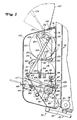
- FIG. 2 shows a winding device 70 which is connected to the Rear and the bottom of the bale discharge gate 20 attached to form bales formed in the bale forming chamber 56, such as the bale 58, before wrapping on the floor.
- the winder 70 in the following is constructed to a strip of to deliver a material designed as a network, the one Width that is greater than the width of the Bale forming chamber 56 to such an extent that the material extends over the end edges of bale 58.
- the winding device 70 contains a supporting frame, the one on the lower half of the back of the Bale unloading gate 20 is mounted and a transverse vertical wall 72 which is between vertical Flanges extends and is attached to this, which the rear ends of the opposing side walls 22 form the bale discharge gate 20.
- the wall 72 has one upper end area that extends from one down and back extending flange 74 is formed.
- Corresponding across extending legs of a pair of angular holder 76 for Carrying lever arms is on upper right and left Areas of the wall 72 screwed below the flange 74.
- a pair of angular supports 80 for holding tension arms is at a vertical distance down to the pair of holders 76 provided and has transverse legs that on the wall 72 are screwed.
- the supporting frame of the Winder 70 also includes a pair of lengthways extending vertical support walls 84, the side view are approximately rectangular and front vertical Have sides formed by transverse flanges that overlap a lower portion of the wall 72 and by means of fasteners not shown thread to the structure in the rear area of the bale unloading gate 20 are attached, so in the transverse direction to have a distance from each other that is greater than that Distance between the side walls 22 of the bale discharge gate 20, d. H. greater than the width of the bale forming chamber 56.
- a pair of feed rollers 86 and 88 extend for the material itself between the support walls 84 and is with its opposite end regions rotatably supported in these, the feed roller 86 opposite the feed roller 88 is arranged offset at the top and rear, in such a way that a trajectory defined by a plane that is in the Area of the gap tangent to the feed rollers 86, 88 extends, runs under the wall 72 and on a vertical run of the straps 42 that meets between the upper and lower straps 42 carrying Roll 36 or 38 extends.
- the trajectory of the material cuts the straps 42 at a location above one Detection point 90 by an area 92 a Mesh guide trough that is part of a wrap guide assembly 93 forms, and an area of Belt 42 is formed which engages the lower rear roll 38 stands.
- the upper feed roller 86 for the Net material is arranged so that it is on the lower Feed roller 88 is clamped for the mesh material.
- in the individual is a U-shaped on the outside of each of the support walls 84 Holder 94 attached.
- a clamp 95 with a Longitudinal slot in which a guide pin 96 or screw is recorded, which is attached to the support wall 84 attached below the holder 94 and has to the outside turned top end portions parallel to each of the holders 94 are arranged.
- a pair of screws 97 extend in each case by the pair of end regions turned outwards Clamp 95 and through the adjacent holder 94 upwards and each is in a set position by a mother 98 held on their upper thread area becomes.
- a coil spring 100 is located on each screw 97 and is between the associated holder 94 and the tension bracket 95 clamped.
- the guide roller 103 is by means of a pin 107 attached to the lever 105, which through a slot 108 on a circle around bearing 106 in the support wall 84 extends.
- the upper feed roller 86 is preferably of the type Metal body formed with rubber with a high Coated friction coefficient and, as shown in Figure 2 emerges, driven counter-clockwise becomes.
- the drive of the feed roller 86 is not shown in FIG Way as a belt transmission with a variable pulley and a pulley, which is attached to a shaft which acts as an extension of the lower roller 38 is connected, so that always a direct relationship between the speed of the belts 42 and the Circumferential speed of the feed rollers 86, 88 for the There is a relatively high tension in the material To produce material while wrapping the bale 58, ideally this voltage is as high as it should be can without breaking the material or during handling of wrapped bale 58 of risk of tearing subject to.
- a roll of material 112 is, if at all, in one small extent carried by a pair of ramps 114 that extend themselves each extend transversely away from the supporting walls 84 and slightly down towards the upper feed roller 86 are inclined and end near a halfway point from this, before any material is used and when the Feed rollers 86 and 88 in a non-driven one Ready state. It is important to note that the tension in the material segment that is between the Guide roller 103 and the feed point between the Material roll 112 and the feed roller 86 extends to this tends to the entire weight of the roll of material 112 on the Shift feed roller 86 when feed rollers 86 and 88 are driven.
- the main purpose of ramps 114 is one Help while inserting the supply roll 112 into your To offer operating position on the feed roller 86.
- a tensioner 116 provided a pair a transverse distance from each other having arms 118, the front end portions to the pair of supports 80 by means of a pair of bolts 120 are pivotally attached.
- a roller 122 is rotatable in the rear end portions of the arms 118 and so on arranged that they have a slight rubbing engagement with the upper maintains rear quadrant of roll of material 112 when the roll of material 112 becomes smaller when the material is added is used to wrap the bale 58.
- the jig 116 also includes a pair of links 124, the lower one End portions each on a pair of pins 126 attached to the arms 118 are welded, pivotally received, and their upper end regions each pivotable somewhat by means of pins 128 to rear legs of a pair of lever arms 130 are attached, each by means of pins 132 to the Pair of holders 76 are pivotally connected.
- a compliant Force to push the roller 122 against the material roller 112 with the winding material is from a pair of energy storage 134th applied in the manner of gas pressure cylinder 134, the Rod ends each by means of a pair of pins 136, for example pivotable to front legs of the pair of lever arms 130 are attached, and the cylinder ends of each by means of a pair of pins 138 on opposite side walls a cover 140 are pivotally connected.
- the lid 140 has an upper wall that is hinged 142 is pivotally attached to the flange 74, which allows that the cover 140 from a lower closed position, as shown in solid lines and in the upright front ends of the side walls at the back of the Bale discharge gate 20 abut in a raised position Position is pivoted by an angle starting from the closed position is more than 90 degrees like this is shown in broken lines.
- the roller 122 against the material roller 112 of the Wrapping material is the geometric connection between the Line of action of the energy storage 124 and the Stite 132 of the Lever arms 130 such that the energy storage 134 over a Move the dead center position and the cover 140 in its open Keep position tense.
- the lid 140 is by means of a Latch 144 held releasably in its closed position, which is received in an opening of a latch holder 146 which extends between and with the support walls 84 connected is.
- a locking lever 148 is on one center of a rear wall of the lid 140 is pivotable attached and so that he can use the latch 144 optionally from or into a locking connection with the bolt holder 146 moves.
- a supply roll 150 for the material is above and in stored in close proximity to the material roll 112.
- Support to carry the supply roll 150 included a pair of upright Leg 152, the end regions turned outward in each case have, which are flexibly secured to horizontal flanges that form the upper sides of the support walls 84.
- in the connection of each leg 152 to the individual assigned support wall 84 by means of a screw 154 manufactured by aligned holes in the Leg end and the flange of the support wall 84 extends and as a coil spring formed spring 156 carries the by means of a nut 158 on the lower end area of the Screw 154 is held stationary.
- One each as a rivet trained projection 159 extends through one outwardly turned end portion of the leg 152 and has a head (not visible), which forms a stop, which in a recess in the relevant horizontal flange Side wall 84 is added.
- One a shelf 160 forming sheet metal plate that is curved along an arc is so as to have an upper concave support surface or saddle form on which the back lower quadrant is one corresponding end region of the supply roll 150 rests, extends a short distance from leg 152 transversely inwards and is attached to it, namely on one Place a distance from the top of leg 152 from pointing down.
- each of manually by the vertical defined by the screw 154 Axis can be rotated like this during the movement of the Supply roll 150 is desired in place once the Roll of material 112 is used up. In particular, becomes Repositioning the supply roll 150, first the cover 140 raised to its open position and the empty roll core the roll of material 112 removed.
- a pair of roller loading supports 161 which are designed as strips and pivotable corresponding locations near the height of the ramps 114 are pivotable are attached so that they are pivoted about upright axes can then become laterally extending Waiting positions as shown in solid lines are, in rearward-extending support positions pivoted, as shown in broken lines.
- the right end portion of the guide roller 103 is then through the movement of the lever 105 in its lower position under the Stop bolt 110 raised.
- the supply roll 150 is then lowered onto the roller loading supports 161.
- the removed supply roll 150 is replaced by the fact that again the cover 140 is opened, the roller loading supports 161 in their loading positions and a new one Supply roll 150 is rolled onto the roll loading supports 161.
- the new supply roll 150 is then placed on the shelves 160 raised, end by end, if desired becomes.
- the lid 140 is then closed.
Landscapes
- Life Sciences & Earth Sciences (AREA)
- Environmental Sciences (AREA)
- Storage Of Harvested Produce (AREA)
- Winding Of Webs (AREA)
Description
- Figur 1
- eine Presse mit einer erfindungsgemäßen Wickelvorrichtung in Seitenansicht und
- Figur 2
- die Wickelvorrichtung in vergrößerter Darstellung und in Seitenansicht.
Claims (8)
- Wickelvorrichtung (70) einer Presse mit wenigstens einer drehend antreibbaren Zuführrolle (86) zum Transportieren eines bahnförmigen Materials von einer Materialrolle (112) zu einer Ballenbildungskammer (56), dadurch gekennzeichnet, daß die Materialrolle (112) auf der Zuführrolle (86) lagert und von dieser in Drehung versetzbar ist.
- Wickelvorrichtung nach Anspruch 1, dadurch gekennzeichnet, daß zwei Zuführrollen (86, 88) vorgesehen sind, die zwischen sich einen Spalt bilden, durch den das Material geführt wird und in dem es kraftschlüssig von den Zuführrollen (86, 88) erfaßt wird.
- Wickelvorrichtung nach Anspruch 1 oder 2, gekennzeichnet durch eine Spannvorrichtung (116) mit einer Rolle (122) und mit einem Kraftspeicher (134), der die Rolle (122) auf die Materialrolle (112) drängt.
- Wickelvorrichtung nach einem oder mehreren der vorherigen Ansprüche, gekennzeichnet durch eine Führungsrolle (103) nahe der mit der Materialrolle (112) in Berührung stehenden Zuführrolle (86) und durch eine Anordnung, die einen Verlauf des Materials von der Materialrolle (112) über die Führungsrolle (103), die Zuführrolle (86) und durch den Spalt ermöglicht.
- Wickelvorrichtung nach einem oder mehreren der vorherigen Ansprüche, gekennzeichnet durch eine Beschichtung wenigstens einer der Zuführrollen (86, 88) mit einem Belag hohen Reibwerts, insbesondere mit Gummi.
- Wickelvorrichtung nach einem oder mehreren der Ansprüche 2 bis 5, dadurch gekennzeichnet, daß beide Zuführrollen (86, 88) übereinander angeordnet sind und sich die Materialrolle (112) auf der oberen Zuführrolle (86) abstützt.
- Wickelvorrichtung nach einem oder mehreren der Ansprüche 3 bis 6, dadurch gekennzeichnet, daß die Rolle (122) an wenigstens einem Arm (118) in Richtung auf die Zuführrolle (86) schwenkbar gelagert ist.
- Wickelvorrichtung nach einem oder mehreren der Ansprüche 4 bis 7, dadurch gekennzeichnet, daß die Führungsrolle (103) verstellbar angeordnet ist.
Applications Claiming Priority (2)
| Application Number | Priority Date | Filing Date | Title |
|---|---|---|---|
| US09/007,940 US5974764A (en) | 1998-01-16 | 1998-01-16 | Large round baler net wrapping device for dispensing net from a supply roll resting on a driven feed roll |
| US7940 | 1998-01-16 |
Publications (2)
| Publication Number | Publication Date |
|---|---|
| EP0941651A1 EP0941651A1 (de) | 1999-09-15 |
| EP0941651B1 true EP0941651B1 (de) | 2000-11-08 |
Family
ID=21728942
Family Applications (1)
| Application Number | Title | Priority Date | Filing Date |
|---|---|---|---|
| EP98123163A Expired - Lifetime EP0941651B1 (de) | 1998-01-16 | 1998-12-04 | Wickelvorrichtung einer Presse |
Country Status (5)
| Country | Link |
|---|---|
| US (1) | US5974764A (de) |
| EP (1) | EP0941651B1 (de) |
| CA (1) | CA2243883C (de) |
| DE (1) | DE59800331D1 (de) |
| ES (1) | ES2151758T3 (de) |
Families Citing this family (27)
| Publication number | Priority date | Publication date | Assignee | Title |
|---|---|---|---|---|
| US6272816B1 (en) * | 1999-11-12 | 2001-08-14 | Deere & Company | Large wrapping net roll pressure arm assembly serving also as a loading platform |
| US6622463B1 (en) * | 1999-11-30 | 2003-09-23 | Deere & Company | Device for folding leading end of net-type bale wrapping material to enhance its full-width conveyance into the baling chamber |
| DE10026066A1 (de) * | 2000-05-25 | 2001-11-29 | Deere & Co | Vorrichtung zum Umhüllen eines Rundballens |
| US6736348B1 (en) * | 2000-06-28 | 2004-05-18 | Georgia-Pacific Corporation | Power transfer system apparatus |
| US6592067B2 (en) | 2001-02-09 | 2003-07-15 | Georgia-Pacific Corporation | Minimizing paper waste carousel-style dispenser apparatus, sensor, method and system with proximity sensor |
| US7102366B2 (en) * | 2001-02-09 | 2006-09-05 | Georgia-Pacific Corporation | Proximity detection circuit and method of detecting capacitance changes |
| US7017856B2 (en) * | 2001-02-09 | 2006-03-28 | Georgia-Pacific Corporation | Static build-up control in dispensing system |
| GB0130465D0 (en) * | 2001-12-20 | 2002-02-06 | Kverneland Asa | Baler and enveloping apparatus |
| US7341170B2 (en) | 2002-03-07 | 2008-03-11 | Georgia-Pacific Consumer Operations Llc | Apparatus and methods usable in connection with dispensing flexible sheet material from a roll |
| DE10211412A1 (de) | 2002-03-15 | 2003-10-09 | Deere & Co | Rundballenpresse |
| US6823646B2 (en) * | 2002-07-19 | 2004-11-30 | New Holland North America, Inc. | Wrapping material brake release |
| DE102005015224A1 (de) * | 2005-04-02 | 2006-10-26 | Deere & Company, Moline | Ladevorrichtung |
| DE102005015226A1 (de) * | 2005-04-02 | 2006-10-26 | Deere & Company, Moline | Ladevorrichtung |
| DE102005015223A1 (de) * | 2005-04-02 | 2006-10-26 | Deere & Company, Moline | Ladevorrichtung |
| US7356981B2 (en) * | 2005-10-04 | 2008-04-15 | Cnh America Llc | Double roll feeder for round baler |
| US20070194166A1 (en) | 2006-02-18 | 2007-08-23 | Georgia-Pacific Consumer Products Lp | Electronic Dispenser for Dispensing Sheet Products |
| US7878446B2 (en) | 2006-10-20 | 2011-02-01 | Georgia-Pacific Consumer Products Lp | Dispenser housing with motorized roller transport |
| US7946095B2 (en) * | 2009-02-03 | 2011-05-24 | Agco Corporation | Meshwrap dispensing mechanism for round balers |
| US8925287B2 (en) * | 2009-03-19 | 2015-01-06 | Deere & Company | Arrangement on baler for ergonomic loading of bale wrapping material rolls |
| US8516779B2 (en) | 2011-03-16 | 2013-08-27 | Duratech Industries International, Inc. | Net wrap applicator for large round bales |
| US9320199B2 (en) * | 2011-11-22 | 2016-04-26 | Cnh Industrial America Llc | Multiple rolls net wrap assembly |
| US10517221B2 (en) | 2013-09-09 | 2019-12-31 | Vermeer Manufacturing Company | Round baler with dual wrapping rolls |
| US10356983B2 (en) | 2014-04-18 | 2019-07-23 | Cnh Industrial America Llc | Indexing net wrap system |
| US10660485B2 (en) | 2017-10-09 | 2020-05-26 | Gpcp Ip Holdings Llc | Dual roll product dispenser with rotating refill carriage |
| CN108120412B (zh) * | 2018-01-24 | 2023-08-22 | 三一汽车制造有限公司 | 间隙检测装置和机械设备 |
| US10820527B2 (en) | 2018-07-13 | 2020-11-03 | Deere & Company | Baler with netwrap roll loading device |
| US10934143B2 (en) | 2018-07-13 | 2021-03-02 | Deere & Company | Net wrap lifting device |
Family Cites Families (13)
| Publication number | Priority date | Publication date | Assignee | Title |
|---|---|---|---|---|
| US2592788A (en) * | 1948-09-28 | 1952-04-15 | Gen Railway Signal Co | Wire terminal and insulating sleeve |
| US3167367A (en) * | 1962-05-17 | 1965-01-26 | Rozlog Matt | Sheet material dispenser |
| NL140809B (nl) * | 1965-04-10 | 1974-01-15 | Kalle Ag | Inrichting voor het constant houden van de baanspanning in een af te wikkelen materiaalbaan. |
| SE407677B (sv) * | 1976-10-18 | 1979-04-09 | Gustavsson Olov Erland | Sett och apparat for att forma ett skyddande holje kring ett prismatiskt eller cylindriskt foremal |
| US4404880A (en) * | 1977-10-14 | 1983-09-20 | Georgia-Pacific Corporation | Method for web cutting in rolled sheet material dispensers |
| FR2478601A1 (fr) * | 1980-03-19 | 1981-09-25 | Sopalin | Perfectionnements aux appareils de distribution de produits en rouleaux, notamment d'essuie-mains en papier |
| US4291845A (en) * | 1980-03-27 | 1981-09-29 | Van Mark Products Corporation | Coil cradle |
| US4497453A (en) * | 1983-05-16 | 1985-02-05 | Butcher Henry P | Dispenser for internally self-supported rolled material |
| JPH0247675B2 (ja) * | 1983-09-14 | 1990-10-22 | Kagaku Gijutsucho | Heriumuekika*reitosochi |
| NO164526C (no) * | 1987-05-13 | 1990-10-17 | Underhaug As | Anordning for kontrollert strekking av en plastfoliebane naar den avtrekkes fra en plastspole. |
| DE4032763A1 (de) * | 1990-10-16 | 1992-04-30 | Deere & Co | Bindevorrichtung fuer die ballen einer ballenpresse |
| US5181368A (en) * | 1991-12-17 | 1993-01-26 | Deere & Company | Housing for holding a supply roll of large round bale wrap material |
| US5687548A (en) * | 1996-05-21 | 1997-11-18 | New Holland North America, Inc. | Dispenser control system for round bale wrapping apparatus |
-
1998
- 1998-01-16 US US09/007,940 patent/US5974764A/en not_active Expired - Lifetime
- 1998-09-03 CA CA002243883A patent/CA2243883C/en not_active Expired - Fee Related
- 1998-12-04 DE DE59800331T patent/DE59800331D1/de not_active Expired - Lifetime
- 1998-12-04 EP EP98123163A patent/EP0941651B1/de not_active Expired - Lifetime
- 1998-12-04 ES ES98123163T patent/ES2151758T3/es not_active Expired - Lifetime
Also Published As
| Publication number | Publication date |
|---|---|
| EP0941651A1 (de) | 1999-09-15 |
| US5974764A (en) | 1999-11-02 |
| ES2151758T3 (es) | 2001-01-01 |
| CA2243883A1 (en) | 1999-07-16 |
| CA2243883C (en) | 2002-01-15 |
| DE59800331D1 (de) | 2000-12-14 |
Similar Documents
| Publication | Publication Date | Title |
|---|---|---|
| EP0941651A1 (de) | Wickelvorrichtung einer Presse | |
| EP0935915B1 (de) | Wickelvorrichtung einer Presse mit einer Materialrolle und einer Vorratsrolle | |
| EP0931449B1 (de) | Presse mit einer Wickelvorrichtung | |
| EP1099366B1 (de) | Hüllmittelzufuhrvorrichtung | |
| DE2851035C2 (de) | Erntegut-Rundballenformmaschine | |
| DE2443838B2 (de) | Aufsammei-Rollballenpresse | |
| EP1214875A1 (de) | Rundballenpresse | |
| EP0740508B1 (de) | Vorrichtung zum aufwickeln eines teigbandes | |
| DE2705334C2 (de) | Schälmaschine für Körnerfrüchte | |
| DE3941707A1 (de) | Rundballenpresse fuer halmfoermiges erntegut | |
| DE2537121C3 (de) | Vorrichtung zum Führen und Zentrieren eines Förderbandes in einer Rund- | |
| DE3501062C2 (de) | ||
| DE2530249B2 (de) | Wickelballenpresse | |
| DE3223784A1 (de) | Ausstossmechanismus fuer eine rundballenpresse | |
| DE4105078A1 (de) | Rundballenpresse | |
| DE69212766T2 (de) | Ballenwickelmaschine | |
| EP0404094A1 (de) | Rundballenpresse mit einer Vorrichtung zum Umhüllen eines in einer Ballenformkammer gewickelten Rundballens | |
| DE2947388C2 (de) | ||
| EP0404105A1 (de) | Rundballenpresse mit einer Vorrichtung zum Umhüllen eines in einer Ballenformkammer gewickelten Rundballens | |
| DE7806036U1 (de) | Rundballenpresse fuer heu und anderes faseriges erntegut mit einer baender-spannvorrichtung fuer die baender zur ballenformung | |
| DE3734186A1 (de) | Aufsammel-rollballenpresse | |
| EP0095689B1 (de) | Rundballenpresse mit einem einen Guteinlass aufweisenden Ballenpressraum | |
| DE10063120A1 (de) | Rundballenpresse | |
| DE20103764U1 (de) | Vorrichtung zum Ein- und/oder Ausschleusen von Fördergut | |
| DE3247011A1 (de) | Rundballen-formmaschine |
Legal Events
| Date | Code | Title | Description |
|---|---|---|---|
| PUAI | Public reference made under article 153(3) epc to a published international application that has entered the european phase |
Free format text: ORIGINAL CODE: 0009012 |
|
| AK | Designated contracting states |
Kind code of ref document: A1 Designated state(s): DE ES FR GB IT |
|
| AX | Request for extension of the european patent |
Free format text: AL;LT;LV;MK;RO;SI |
|
| 17P | Request for examination filed |
Effective date: 19991218 |
|
| GRAG | Despatch of communication of intention to grant |
Free format text: ORIGINAL CODE: EPIDOS AGRA |
|
| GRAG | Despatch of communication of intention to grant |
Free format text: ORIGINAL CODE: EPIDOS AGRA |
|
| GRAH | Despatch of communication of intention to grant a patent |
Free format text: ORIGINAL CODE: EPIDOS IGRA |
|
| 17Q | First examination report despatched |
Effective date: 20000303 |
|
| AKX | Designation fees paid |
Free format text: DE ES FR GB IT |
|
| GRAH | Despatch of communication of intention to grant a patent |
Free format text: ORIGINAL CODE: EPIDOS IGRA |
|
| GRAA | (expected) grant |
Free format text: ORIGINAL CODE: 0009210 |
|
| AK | Designated contracting states |
Kind code of ref document: B1 Designated state(s): DE ES FR GB IT |
|
| REF | Corresponds to: |
Ref document number: 59800331 Country of ref document: DE Date of ref document: 20001214 |
|
| ET | Fr: translation filed | ||
| ITF | It: translation for a ep patent filed | ||
| REG | Reference to a national code |
Ref country code: ES Ref legal event code: FG2A Ref document number: 2151758 Country of ref document: ES Kind code of ref document: T3 |
|
| GBT | Gb: translation of ep patent filed (gb section 77(6)(a)/1977) |
Effective date: 20010131 |
|
| PLBE | No opposition filed within time limit |
Free format text: ORIGINAL CODE: 0009261 |
|
| STAA | Information on the status of an ep patent application or granted ep patent |
Free format text: STATUS: NO OPPOSITION FILED WITHIN TIME LIMIT |
|
| 26N | No opposition filed | ||
| REG | Reference to a national code |
Ref country code: GB Ref legal event code: IF02 |
|
| PGFP | Annual fee paid to national office [announced via postgrant information from national office to epo] |
Ref country code: GB Payment date: 20131227 Year of fee payment: 16 |
|
| PGFP | Annual fee paid to national office [announced via postgrant information from national office to epo] |
Ref country code: IT Payment date: 20131228 Year of fee payment: 16 Ref country code: ES Payment date: 20131226 Year of fee payment: 16 |
|
| PGFP | Annual fee paid to national office [announced via postgrant information from national office to epo] |
Ref country code: FR Payment date: 20141217 Year of fee payment: 17 |
|
| GBPC | Gb: european patent ceased through non-payment of renewal fee |
Effective date: 20141204 |
|
| PG25 | Lapsed in a contracting state [announced via postgrant information from national office to epo] |
Ref country code: GB Free format text: LAPSE BECAUSE OF NON-PAYMENT OF DUE FEES Effective date: 20141204 |
|
| PG25 | Lapsed in a contracting state [announced via postgrant information from national office to epo] |
Ref country code: IT Free format text: LAPSE BECAUSE OF NON-PAYMENT OF DUE FEES Effective date: 20141204 |
|
| REG | Reference to a national code |
Ref country code: ES Ref legal event code: FD2A Effective date: 20160129 |
|
| PG25 | Lapsed in a contracting state [announced via postgrant information from national office to epo] |
Ref country code: ES Free format text: LAPSE BECAUSE OF NON-PAYMENT OF DUE FEES Effective date: 20141205 |
|
| REG | Reference to a national code |
Ref country code: FR Ref legal event code: ST Effective date: 20160831 |
|
| PG25 | Lapsed in a contracting state [announced via postgrant information from national office to epo] |
Ref country code: FR Free format text: LAPSE BECAUSE OF NON-PAYMENT OF DUE FEES Effective date: 20151231 |
|
| PGFP | Annual fee paid to national office [announced via postgrant information from national office to epo] |
Ref country code: DE Payment date: 20171231 Year of fee payment: 20 |
|
| REG | Reference to a national code |
Ref country code: DE Ref legal event code: R071 Ref document number: 59800331 Country of ref document: DE |