EP0940794A2 - Verfahren und Vorrichtung zum verkehrsabhängigen Steuern von Mitteln zur Verkehrsbeeinflussung - Google Patents
Verfahren und Vorrichtung zum verkehrsabhängigen Steuern von Mitteln zur Verkehrsbeeinflussung Download PDFInfo
- Publication number
- EP0940794A2 EP0940794A2 EP99104497A EP99104497A EP0940794A2 EP 0940794 A2 EP0940794 A2 EP 0940794A2 EP 99104497 A EP99104497 A EP 99104497A EP 99104497 A EP99104497 A EP 99104497A EP 0940794 A2 EP0940794 A2 EP 0940794A2
- Authority
- EP
- European Patent Office
- Prior art keywords
- traffic
- control
- influencing
- values
- rule
- Prior art date
- Legal status (The legal status is an assumption and is not a legal conclusion. Google has not performed a legal analysis and makes no representation as to the accuracy of the status listed.)
- Granted
Links
Images

Classifications
-
- G—PHYSICS
- G08—SIGNALLING
- G08G—TRAFFIC CONTROL SYSTEMS
- G08G1/00—Traffic control systems for road vehicles
- G08G1/07—Controlling traffic signals
- G08G1/08—Controlling traffic signals according to detected number or speed of vehicles
Definitions
- the invention relates to a method and an apparatus for the traffic-dependent control of means for influencing traffic according to the preamble of the claim 1.
- Traffic-dependent traffic influencing takes place nowadays for example via traffic signal systems, variable message signs, changeable parking space information signs or radio announcements.
- the traffic-dependent data are over Traffic detectors such as induction loops, radar or infrared detectors won.
- phase sequences or signal sequences determined by predetermined signal programs are depending on the chosen control method variable. So with traffic-dependent control procedures for example the duration of the individual phases, the order of the individual phases and the number of different Phases (if required) in the signal program changed. With time-dependent control procedures are set at fixed times of the day (e.g. in commuter traffic) different signal programs and thus different phase sequences switched.
- the sequence of phases or the number of phases traffic-related parameters are evaluated, which with Help the traffic detectors be determined.
- the design processing implemented off-line In case of a Signal program adaptation or signal program formation are the Parameters processed continuously, with the possibility a changing influence between traffic flow and Signal control.
- the current signal programs are included according to a given control logic based on each updated parameters calculated and evaluated online. With the help of traffic detectors are in the spatial environment the traffic signal system detects occupancy values, from which parameters of the traffic flow are derived.
- the waiting time of the vehicles serves as parameters in front of the traffic signal system, the traffic jam length in front of the Traffic signal system, the traffic volume, i.e. Vehicles per Cross section, the driving speed, a registration (Request) by pedestrians, cyclists and / or vehicles, the degree of occupancy, the traffic density, the degree of utilization and the load quotient.
- the processed parameters of the Traffic flow in the control logic for the selection of the signal programs with condition equations and threshold values connected.
- the object is achieved by a method of the beginning mentioned type with the characterizing features of the claim 1 solved.
- condition equations are stored in a common database file as well as actions that take place within a given Transition of a momentary state within the framework in a better adapted to the current traffic flow updated state to run and rules that the Link condition equations and the actions together, saved.
- the embodiment according to claim 4 is particularly flexible, according to which the control hierarchies can be changed by within of the database files referenced to database files that do not follow directly in the processing order.
- the method can be modified in such an advantageous manner Traffic conditions that are only caused by an outside of the given adjustment and / or selection of the Control program can be taken into account, thereby adapt that according to claim 5, the condition equations that Rules and / or the actions of the database files changed and saved.
- current signal sequence current signal program
- current status by another signal sequence (further signal program) replaced as an updated state.
- the current tax strategy as the current status through a further control strategy replaced as an updated state.
- the structure common to all database files according to claim 9 allows implementation in the database file described determination of the current control program through an algorithm common to all database files.
- condition equations By composing condition equations through logical Links from individual conditions according to claim 12 and their logical combination according to claim 13 can handle complex control conditions in a clear, flexible manner be summarized.
- Figure 1 is a traffic signal system 1 as an example of a means of influencing traffic, the procedure is also for variable message signs, parking space information signs or to determine diversion measures or automatic radio announcements suitable as well Change from current to other control strategies in traffic management systems.
- two light signal generators 2 controlled via a control unit 3 the cable connections are laid within a whip mast 4, the at the same time as a fastening device for the light signal transmitter 2 serves.
- the traffic lights 2 With the traffic lights 2 the traffic on a first lane 5 (for example into the city) regulated by a median 7 from a second Lane 8 in the opposite direction of travel (for example out of town).
- Two traffic detectors 10, for example Inductive loops take occupancy values from Vehicles in a first measurement cross section 6 on the first Lane 5 and in a second measurement cross section 9 of the second Lane 7 on, transfer them to the control unit 3, in the from this parameters of the traffic flow in the first lane 5 and the second lane 8 can be determined.
- the currently switched Signal sequences (current signal program, current status) within of the control unit 3 based on the current traffic flow evaluated and by means of a control program in the control unit 3 may become one for the current traffic flow more suitable further signal sequence (further signal program, updated state) with which the traffic signal system 1 is then operated to a to achieve improved traffic flow.
- further signal sequence further signal program, updated state
- FIG 2 is a conventional flow diagram for the transition a phase 1 into a phase 2 and from phase 2 into a Phase 3 shown, with the vehicles in phase 2 the first lane 5 receive an enable signal.
- the phase transition PÜ 1,2 from phase 1 to phase 2 lasts 15 s, as shown in an action element 11. While phase 2 becomes the time t that has passed since the phase transition Phase 2 has passed, measured and with the shortest amount of time T1 compared to phase 2 as is in a decision element 12 is shown for temporal conditions. So long as the temporal condition equation that the elapsed Time t is greater than the shortest time period T1 Truth value "false" or "no N" is given in one Time loop 14 waited.
- the logical condition equation B1 receives the truth value "false N”, then it is checked whether the elapsed Time t has been greater since the phase transition to phase 2 than the longest period of time T2 of phase 2. Receives this second temporal condition equation the truth value "true J ", the phase transition PÜ 2,3 from phase 2 also becomes Phase 3 initiated. Receives this second temporal condition equation the truth value "false N”, then in one another time loop in a next time step initially the logical condition equation B1 evaluated again. For more complex traffic signal systems than in this example described, the flowchart quickly becomes confusing, complicated to change and is difficult automatic to implement in a traffic description, which is used in the control program of control unit 3 can be.
- a first situation S1 little traffic
- a second situation S2 day traffic
- a third situation S3 peak traffic in the city
- a fourth situation S4 peak traffic out of town
- a fifth situation S5 peak traffic balanced.
- Individual conditions are used to describe the traffic flow, which relate determined parameters to predefined threshold values.
- the individual conditions in this example are a first individual condition b1, which means that the traffic volume in the first measurement cross-section 6 is greater than a threshold value of 800 vehicles per hour, a second individual condition b2, which means that the speed in the first measurement cross-section 6 is less than the threshold value is 30 km / h, a third individual condition b3, which states that the traffic volume in the second measurement cross-section 6 is greater than 800 vehicles per hour, and the one individual condition which states that the speed in this second measurement cross-section 8 is less than 30 km / h. If the first and second individual conditions b1, b2 for the first measuring cross-section 6 are met, this corresponds to a peak traffic towards the city, which is described by the second condition equation B2.
- the third and fourth individual conditions b3, b4 are met for the second measuring cross-section 9, there is a peak traffic out of town, which is described in the third condition equation B3 by an AND operation of the third and fourth individual conditions b3, b4 .
- the first condition equation B1 describes a balanced peak traffic, which is characterized in that all four individual conditions are met.
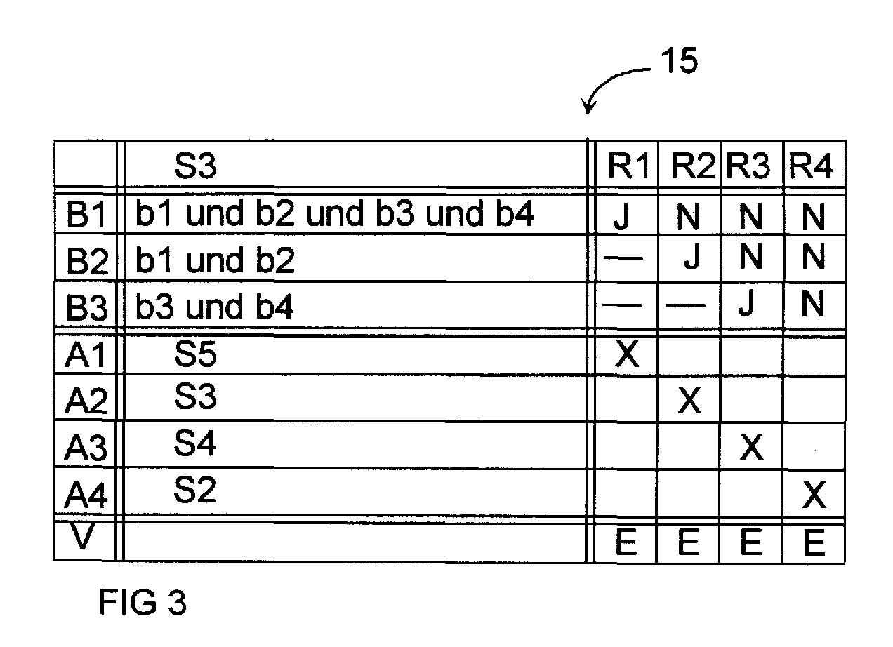
- the condition equations are stored in a first field of a database file 15 as a decision table, which in this example is based on the currently activated third situation S3.
- the possible actions for the signal program selection are stored in a second field of the database file 15. In FIG.
- Actions A1, A2, A3, A4 are selected with the aid of rules R1..R4 stored in a third field in database file 15.
- the rules R1 to R4 consist of rule values and action notes.
- each rule a condition value is assigned to each condition, which indicates whether the condition has to assume the truth value "true J", the truth value "false N” or any truth value "-” so that the action corresponding to the action note is carried out.
- FIG. 3 shows that in the first rule R1 the first condition equation B1 must receive the truth value "true J”, the truth values of the two other condition equations B2, B3 are not taken into account, and that the action instruction X then refers to the first action A1 with which the balanced peak traffic is switched.
- the second rule describes that in the event that the first condition equation B1 has the truth value "false N", the second condition equation B2 the truth value "true J” and the third condition equation B3 has an arbitrary truth value, the action instruction X for the second action A2 indicates in which the signal program for inbound peak traffic continues to be switched.
- the third rule R3, with its action note X, indicates the third action A3, in which a switch is made to the out-of-town traffic when the first and the second condition equations B1, B2 the truth value "false N" and the third condition equation B3 the truth value " true J ".
- the fourth rule R4 shows an action instruction X on the fourth action A4, in which the switch is made to the second situation S2, which is carried out when all condition equations B1, B2, B3 receive the truth value "false N".
- a linkage action V is stored in a fourth field, which contains further steps to be carried out after the action performed. In this example, processing is terminated with a termination notice E (Exit).
- FIG. 4 shows how linking actions V, after completing actions A1 ... A4, a modular compilation achieved by several database files D1 ... D4 becomes.
- a fixed processing order 20 defines in which the individual database files D1 ... D4 in a fixed order as a control hierarchy to be brought.
- a third database file is created D3, then a second database file D2, then a first database file D1 and finally a fourth Database file 4 edited.
- the linking actions V in the individual database files D1 ... D4 also allow to change the fixed processing sequence 20.
- the database files D1 ... D4 as done by the link action 21 to the address of the subsequent one Table is indicated, processed in the processing order 20.
- the conditions, the rules, the actions, the linking actions or the processing sequences must be adapted in the database files 15, if necessary.
- individual conditions b1, b2, b3, b4 can be linked to condition equations by Boolean operators. Calculations can also be carried out within the actions, which are used in later database files 15 of a processing sequence 20. Due to the identical structure of different database files 15, an algorithm common to all database files 15 can also be specified, with which the contents of the database files 15 are implemented in a traffic-technical description for the control unit 3.
- the method according to the invention can be transferred analogously to traffic management systems in which, on the basis of occupancy values, current control strategies are replaced by further control strategies, which are then implemented by diversion measures, changed displays of variable message signs or parking space information signs or by radio announcements.
Landscapes
- Physics & Mathematics (AREA)
- General Physics & Mathematics (AREA)
- Traffic Control Systems (AREA)
- Devices For Checking Fares Or Tickets At Control Points (AREA)
Abstract
Description
Das erfindungsgemäße Verfahren läßt sich analog auf Verkehrsmanagementsysteme übertragen, in denen anhand von Belegungswerten momentane Steuerstrategien durch weitere Steuerstrategien ersetzt werden, die dann durch Umleitungsmaßnahmen, veränderte Anzeigen von Wechselverkehrszeichen oder Parkraum-Informationsschildern oder durch Radiodurchsagen umgesetzt werden.
Claims (15)
- Verfahren zum verkehrsabhängigen Steuern von Mitteln zur Verkehrsbeeinflussung (1) mit Verkehrsdetektoren (10), die Belegungswerte in Meßquerschnitten (6,9) in der räumlichen Umgebung der Mittel zur Verkehrsbeeinflussung (1) detektieren, mit einem Steuergerät (3), an das die Belegungswerte übermittelt werden, das aus den übermittelten Belegungswerten mittels eines Steuerprogrammes aufbereitete Kenngrößen des Verkehrsablaufs für einen Momentanzustand der Mittel zur Vekehrsbeeinflussung (1) ermittelt, diese aufbereiteten Kenngrößen nach vorgegebenen Bedingungsgleichungen (B1,B2,B3) mit vorgegebenen Schwellenwerten vergleicht und daraus innerhalb eines vorgegebenen Rahmens ein gegenüber dem Momentanzustand aktualisierten Zustand ermittelt, mit der die Mittel zur Verkehrsbeeinflussung (1) dann weiterbetrieben werden,
dadurch gekennzeichnet,daß die Bedingungsgleichungen (B1,B2,B3) in einer dem Steuerprogramm zugeordneten Datenbankdatei (15) abgespeichert werden,daß in der Datenbankdatei (15) ferner Aktionen (A1,A2,A3,A4) abgespeichert werden, die Schritte von dem momentanen zum aktualisierten Zustand definieren,daß in der Datenbankdatei (15) ferner Regeln (R1,R2,R3,R4) abgespeichert werden, die jeweils eine der Anzahl der Bedingungsgleichungen entsprechende Anzahl von Regelwerten sowie einen Aktionshinweis (X) enthalten, wobei in jeder Regel (R1,R2,R3,R4) jeder Bedingungsgleichung (B1,B2,B3) einer von drei möglichen Regelwerten zugeordnet ist, die angeben, ob die jeweilige Bedingungsgleichung einen Wahrheitswert wahr (J), einen Wahrheitswert falsch (N) oder einen beliebigen Wahrheitswert anzunehmen hat, damit die Aktion (A1,A2,A3,A4), auf die der Aktionshinweis (X) der jeweiligen Regel (R1,R2,R3,R4) verweist, ausgeführt wird,daß die aufbereiteten Kenngrößen mit den vorgegebenen Schwellenwerten gemäß den Bedingungsgleichungen (B1,B2,B3) der Datenbankdatei (15) verglichen werden und der Wahrheitswert der jeweiligen Bedingungsgleichung (B1,B2,B3) als Ergebnis des Vergleichs abgespeichert wird,daß die Wahrheitswerte mit den Regelwerten verglichen werden und daß bei einer Übereinstimmung der Wahrheitswerte mit allen Regelwerten einer einzelnen Regel (R1,R2,R3,R4) die jeweilige Aktion (A1,A2,A3,A4) ausgeführt wird, auf die der Aktionshinweis (X) dieser einzelnen Regel (R1,R2,R3,R4) verweist. - Verfahren zum verkehrsabhängigen Steuern von Mitteln zur Verkehrsbeeinflussung (1) nach Anspruch 1,
dadurch gekennzeichnet,
daß der aktualisierte Zustand derart ermittelt wird, daß die Aktionen (A1,A2,A3,A4) Verknüpfungsaktionen (E) umfassen, die auf Adressen weiterer Datenbankdateien (15) verweisen, wodurch die Datenbankdateien (15) untereinander modulartig miteinander verknüpft werden. - Verfahren zum verkehrsabhängigen Steuern von Mitteln zur Verkehrsbeeinflussung (1) nach Anspruch 2,
dadurch gekennzeichnet,
daß mittels der Verknüpfungsaktionen (E) mehrere Datenbankdateien (15) in einer vorgegebenen Bearbeitungsreihenfolge (20) verknüpft werden, wodurch eine Steuerungshierarchie aufgebaut wird, in der die mehreren Datenbankdateien (15) nacheinander ausgewertet werden. - Verfahren zum verkehrsabhängigen Steuern von Mitteln zur Verkehrsbeeinflussung (1) nach Anspruch 3,
dadurch gekennzeichnet,
daß mittels dieser Verknüpfungsaktionen (E) auch auf Datenbankdateien (15) verwiesen wird, die nicht direkt in der Bearbeitungsreihenfolge (20) nachfolgen, so daß damit die Steuerungshierarchie veränderbar ist. - Verfahren zum verkehrsabhängigen Steuern von Mitteln zur Verkehrsbeeinflussung (1) nach einem der Ansprüche 3 oder 4,
dadurch gekennzeichnet,daß die Aktionen (A1,A2,A3,A4) Berechnungsvorschriften umfassen,daß bei Ausführung der Aktionen (A1,A2,A3,A4) Ergebnisse anhand der Berechnungsvorschriften ermittelt und abgespeichert werdenund daß in den Bedingungsgleichungen (B1,B2,B3) von in der Steuerungshierarchie nachfolgenden Datenbankdateien (15) diese Ergebnisse berücksichtigt werden. - Verfahren zum verkehrsabhängigen Steuern von Mitteln zur Verkehrsbeeinflussung (1) nach einem der Ansprüche 1 bis 5,
dadurch gekennzeichnet,
daß beim Auftreten von gegenüber dem vorgegebenen Rahmen derart abweichenden Verkehrsabläufen, daß kein aktualisierter Zustand vorgesehen ist, die Bedingungsgleichungen (B1,B2,B3), die Regeln (R1,R2,R3,R4) und/oder die Aktionen (A1,A2,A3,A4) der Datenbankdateien (15) verändert und die veränderten Bedingungsgleichungen (B1,B2,B3), Regeln (R1,R2,R3,R4) und Aktionen (A1,A2,A3,A4) abgespeichert werden. - Verfahren zum verkehrsabhängigen Steuern von Mitteln zur Verkehrsbeeinflussung (1) nach einem der Ansprüche 1 bis 6,
dadurch gekennzeichnet,
daß bei einer Verkehrssignalanlage (1) als Mittel zur Verkehrsbeeinflussung ein momentanes Signalprogramm als Momentanzustand durch ein weiteres Signalprogramm als aktualisierter Zustand ersetzt wird. - Verfahren zum verkehrsabhängigen Steuern von Mitteln zur Verkehrsbeeinflussung (1) nach einem der Ansprüche 1 bis 6,
dadurch gekennzeichnet,
daß bei einem Verkehrsmanagementsystem (1) als Mittel zur Verkehrsbeeinflussung eine momentane Steuerstrategie als Momentanzustand durch eine weitere Steuerstrategie als aktualisierter Zustand ersetzt wird. - Vorrichtung zum verkehrsabhängigen Steuern von Mitteln zur Verkehrsbeeinflussung (1) mit Verkehrsdetektoren (10), die Belegungswerte in Meßquerschnitten (6,9) in der räumlichen Umgebung der Mittel zur Verkehrsbeeinflussung (1) detektieren, mit einem Steuergerät (3), mit einem Steuergerät (3), an das die Belegungswerte übermittelt werden, das aus den übermittelten Belegungswerten mittels eines Steuerprogrammes aufbereitete Kenngrößen des Verkehrsablaufs für einen Momentanzustand der Mittel zur Verkehrsbeeinflussung (1) ermittelt, diese aufbereiteten Kenngrößen nach vorgegebenen Bedingungsgleichungen (B1,B2,B3) mit vorgegebenen Schwellenwerten vergleicht und daraus innerhalb eines vorgegebenen Rahmens ein gegenüber des Momentanzustands aktualisierter Zustand ermittelt, mit der die Mittel zur Verkehrsbeeinflussung (1) dann weiterbetrieben werden,
dadurch gekennzeichnet,daß das Steuerprogramm Datenbankdateien (15) mit einer identischen Struktur aus Feldern umfaßt,daß in einem ersten Feld die Bedingungsgleichungen (B1,B2,B3) abgespeichert sind,daß in einem zweiten Feld Aktionen (A1,A2,A3,A4) abgespeichert sind, die Schritte vom momentanen zum aktualisierten Zustand definieren,daß in einem dritten Feld Regeln (R1,R2,R3,R4) abgespeichert sind, die jeweils eine der Anzahl der Bedingungsgleichungen entsprechende Anzahl von Regelwerten sowie einen Aktionshinweis (X) enthalten, wobei in jeder Regel (R1,R2,R3,R4) jeder Bedingungsgleichung (B1,B2,B3) einer von drei möglichen Regelwerten zugeordnet ist, die angeben, ob die jeweilige Bedingungsgleichung einen Wahrheitswert wahr (J), einen Wahrheitswert falsch (N) oder einen beliebigen Wahrheitswert anzunehmen hat, damit die Aktion (A1,A2,A3,A4), auf die der Aktionshinweis (X) der jeweiligen Regel (R1,R2,R3,R4) verweist, ausgeführt wird. - Vorrichtung zum verkehrsabhängigen Steuern von Mitteln zur Verkehrsbeeinflussung (1) nach Anspruch 9,
dadurch gekennzeichnet,
daß im zweiten Feld zusätzlich zur jeweiligen Aktion eine Verknüpfungsaktion in Form einer Adresse einer anschließend zu bearbeitenden weiteren Datenbankdatei (15) abgespeichert ist. - Vorrichtung zum verkehrsabhängigen Steuern von Mitteln zur Verkehrsbeeinflussung (1) nach einem der Ansprüche 9 oder 10,
dadurch gekennzeichnet,
daß in einem vierten Feld eine Verknüpfungsaktion in Form einer Adresse einer anschließend zu bearbeitenden weiteren Datenbankdatei (15) abgespeichert ist. - Vorrichtung zum verkehrsabhängigen Steuern von Mitteln zur Verkehrsbeeinflussung (1) nach einem der Ansprüche 9 bis 11,
dadurch gekennzeichnet,
daß die Bedingungsgleichungen (B1,B2,B3) aus Einzelbedingungen (b1,b2) zusammengesetzt sind. - Vorrichtung zum verkehrsabhängigen Steuern von Mitteln zur Verkehrsbeeinflussung (1) nach Anspruch 12,
dadurch gekennzeichnet,
daß die Einzelbedingungen (b1,b2) in den Bedingungsgleichungen (B1,B2,B3)logisch miteinander verknüpft sind. - Vorrichtung zum verkehrsabhängigen Steuern von Mitteln zur Verkehrsbeeinflussung nach einem der Ansprüche 9 bis 13,
dadurch gekennzeichnet,
daß die Mittel zur Verkehrsbeeinflussung als Verkehrssignalanlagen (1) ausgebildet sind, deren momentane Signalfolge als Momentanzustand durch eine weitere Signalfolge als aktualisierter Zustand ersetzt wird. - Vorrichtung zum verkehrsabhängigen Steuern von Mitteln zur Verkehrsbeeinflussung nach einem der Ansprüche 9 bis 13,
dadurch gekennzeichnet,
daß die Mittel zur Verkehrsbeeinflussung als Verkehrsmanagementsysteme ausgebildet sind, deren momentane Steuerstrategie als Momentanzustand durch eine weitere Steuerstrategie als aktualisierter Zustand ersetzt wird.
Applications Claiming Priority (2)
| Application Number | Priority Date | Filing Date | Title |
|---|---|---|---|
| DE19809430 | 1998-03-05 | ||
| DE19809430 | 1998-03-05 |
Publications (3)
| Publication Number | Publication Date |
|---|---|
| EP0940794A2 true EP0940794A2 (de) | 1999-09-08 |
| EP0940794A3 EP0940794A3 (de) | 2000-09-13 |
| EP0940794B1 EP0940794B1 (de) | 2004-10-27 |
Family
ID=7859809
Family Applications (1)
| Application Number | Title | Priority Date | Filing Date |
|---|---|---|---|
| EP99104497A Expired - Lifetime EP0940794B1 (de) | 1998-03-05 | 1999-03-05 | Verfahren und Vorrichtung zum verkehrsabhängigen Steuern von Mitteln zur Verkehrsbeeinflussung |
Country Status (5)
| Country | Link |
|---|---|
| US (1) | US6313757B1 (de) |
| EP (1) | EP0940794B1 (de) |
| AT (1) | ATE280987T1 (de) |
| DE (1) | DE59910920D1 (de) |
| DK (1) | DK0940794T3 (de) |
Families Citing this family (10)
| Publication number | Priority date | Publication date | Assignee | Title |
|---|---|---|---|---|
| US6617981B2 (en) * | 2001-06-06 | 2003-09-09 | John Basinger | Traffic control method for multiple intersections |
| US8253592B1 (en) * | 2007-11-26 | 2012-08-28 | Rhythm Engineering, LLC | External adaptive control systems and methods |
| GB0802205D0 (en) * | 2008-02-06 | 2008-03-12 | Hatton Traffic Man Ltd | Traffic control system |
| EP2187369A3 (de) * | 2008-06-04 | 2012-03-28 | Roads and Traffic Authority of New South Wales | System zur Verkehrssignalregelung |
| EP2308035A4 (de) * | 2008-06-13 | 2011-10-19 | Tmt Services And Supplies Pty Ltd | Verkehrsleitsystem und verfahren |
| US20100057338A1 (en) * | 2008-09-04 | 2010-03-04 | International Business Machines Corporation | Method and system for route tracking |
| US20110175753A1 (en) * | 2010-01-15 | 2011-07-21 | James Jacob Free | Robotic influenced self scheduling F.L.O.W. trafic management system |
| US9978270B2 (en) | 2014-07-28 | 2018-05-22 | Econolite Group, Inc. | Self-configuring traffic signal controller |
| EP4307270B1 (de) | 2022-07-14 | 2025-01-29 | Kapsch TrafficCom AG | Verfahren und server zum steuern von verkehrsampeln |
| CN115481108B (zh) * | 2022-09-19 | 2023-06-13 | 北京三维天地科技股份有限公司 | 一种针对同一数据在不同部门之间的管理方法及系统 |
Family Cites Families (6)
| Publication number | Priority date | Publication date | Assignee | Title |
|---|---|---|---|---|
| US3660812A (en) | 1970-05-01 | 1972-05-02 | Sumitomo Electric Industries | Road traffic control system |
| US4370718A (en) * | 1979-02-06 | 1983-01-25 | Chasek Norman E | Responsive traffic light control system and method based on conservation of aggregate momentum |
| US5257194A (en) | 1991-04-30 | 1993-10-26 | Mitsubishi Corporation | Highway traffic signal local controller |
| JP2655953B2 (ja) * | 1991-07-19 | 1997-09-24 | 株式会社日立製作所 | 交通制御システム |
| SE470367B (sv) * | 1992-11-19 | 1994-01-31 | Kjell Olsson | Sätt att prediktera trafikparametrar |
| DE4408547A1 (de) * | 1994-03-14 | 1995-10-12 | Siemens Ag | Verfahren zur Verkehrserfassung und Verkehrssituationserkennung auf Autostraßen, vorzugsweise Autobahnen |
-
1999
- 1999-03-03 US US09/261,186 patent/US6313757B1/en not_active Expired - Fee Related
- 1999-03-05 AT AT99104497T patent/ATE280987T1/de not_active IP Right Cessation
- 1999-03-05 EP EP99104497A patent/EP0940794B1/de not_active Expired - Lifetime
- 1999-03-05 DK DK99104497T patent/DK0940794T3/da active
- 1999-03-05 DE DE59910920T patent/DE59910920D1/de not_active Expired - Lifetime
Also Published As
| Publication number | Publication date |
|---|---|
| ATE280987T1 (de) | 2004-11-15 |
| EP0940794B1 (de) | 2004-10-27 |
| EP0940794A3 (de) | 2000-09-13 |
| DK0940794T3 (da) | 2005-02-21 |
| DE59910920D1 (de) | 2004-12-02 |
| US6313757B1 (en) | 2001-11-06 |
Similar Documents
| Publication | Publication Date | Title |
|---|---|---|
| DE3603336C2 (de) | ||
| DE102016203522B4 (de) | Verfahren und Vorrichtung zum Vorhersagen von Trajektorien eines Kraftfahrzeugs | |
| DE10354322A1 (de) | Verfahren und System zur Ermittlung der Fahrsituation | |
| DE102018132520A1 (de) | Verfahren sowie System zum Steuern eines Kraftfahrzeugs | |
| EP2149131A1 (de) | Verfahren und vorrichtung zur erkennung von verkehrsrelevanten informationen | |
| DE102010052702A1 (de) | Verfahren zur Steuerung einer Lichtsignalanlage und zugehörige Lichtsignalanlage | |
| EP0940794B1 (de) | Verfahren und Vorrichtung zum verkehrsabhängigen Steuern von Mitteln zur Verkehrsbeeinflussung | |
| DE102020002993A1 (de) | Verfahren zur Unterstützung eines Fahrzeuges | |
| DE102020113611A1 (de) | Verfahren und Sicherheitssystem zum Absichern einer automatisierten Fahrzeugfunktion und Kraftfahrzeug | |
| DE102011113722A1 (de) | Verfahren zur Unterstützung eines Fahrers beim Führen eines Fahrzeugs | |
| EP4532287B1 (de) | Verfahren zum unterstützen eines fahrers beim nutzen einer fahrerassistenzfunktion in einem kraftfahrzeug sowie kraftfahrzeug | |
| DE102012214164B3 (de) | Verfahren und Vorrichtung zur dynamischen Steuerung mindestens einer Lichtsignalanlage | |
| DE69815610T2 (de) | Kraftfahrzeug-Informationenanzeigesystem | |
| EP3947075B1 (de) | Fahrsystem und verfahren zum auswählen einer handlungsoption für ein automatisiertes kraftfahrzeug | |
| DE102018007293A1 (de) | Verfahren zum Betrieb eines im autonomen Fahrbetrieb fahrenden Fahrzeuges | |
| DE102010048675A1 (de) | Prognostizieren von Phasenübergängen an ineinander übergehenden Stauphasen | |
| DE102017206862B4 (de) | Auswählen einer Handlungsoption betreffend die Längsführung eines Kraftfahrzeugs mit zumindest automatisierter Längsführung | |
| DE102006060849A1 (de) | Verfahren zur Ermittlung eines Fahrerzustands | |
| DE19601831C5 (de) | Verfahren zur Erkennung von relevanten Objekten | |
| DE102022104785A1 (de) | Verbessertes Überholmanöver zum Überholen eines vorausfahrenden Drittfahrzeugs | |
| DE102015202434A1 (de) | Verfahren und Vorrichtung zur dynamischen Steuerung einer Signalanlage | |
| DE10025039C2 (de) | Verfahren zur Ermittlung von Verkehrsregelungsphasendauern | |
| DE102018007298A1 (de) | Verfahren zur Routenplanung | |
| EP4279351B1 (de) | Verfahren zur einstellung einer tempomatfunktion mit automatischer abstandseinstellung in einem einspurfahrzeug | |
| DE19841457B4 (de) | Verfahren zur Ermittlung eines verkehrsabhängigen Signalprogrammes für Signalgruppen von Lichtsignalanlagen |
Legal Events
| Date | Code | Title | Description |
|---|---|---|---|
| PUAI | Public reference made under article 153(3) epc to a published international application that has entered the european phase |
Free format text: ORIGINAL CODE: 0009012 |
|
| AK | Designated contracting states |
Kind code of ref document: A2 Designated state(s): AT BE CH DE DK FR GB IT LI NL |
|
| AX | Request for extension of the european patent |
Free format text: AL;LT;LV;MK;RO;SI |
|
| PUAL | Search report despatched |
Free format text: ORIGINAL CODE: 0009013 |
|
| AK | Designated contracting states |
Kind code of ref document: A3 Designated state(s): AT BE CH CY DE DK ES FI FR GB GR IE IT LI LU MC NL PT SE |
|
| AX | Request for extension of the european patent |
Free format text: AL;LT;LV;MK;RO;SI |
|
| 17P | Request for examination filed |
Effective date: 20010312 |
|
| AKX | Designation fees paid |
Free format text: AT BE CH DE DK FR GB IT LI NL |
|
| 17Q | First examination report despatched |
Effective date: 20030612 |
|
| GRAP | Despatch of communication of intention to grant a patent |
Free format text: ORIGINAL CODE: EPIDOSNIGR1 |
|
| GRAS | Grant fee paid |
Free format text: ORIGINAL CODE: EPIDOSNIGR3 |
|
| GRAA | (expected) grant |
Free format text: ORIGINAL CODE: 0009210 |
|
| AK | Designated contracting states |
Kind code of ref document: B1 Designated state(s): AT BE CH DE DK FR GB IT LI NL |
|
| REG | Reference to a national code |
Ref country code: GB Ref legal event code: FG4D Free format text: NOT ENGLISH |
|
| REG | Reference to a national code |
Ref country code: CH Ref legal event code: EP |
|
| REG | Reference to a national code |
Ref country code: CH Ref legal event code: NV Representative=s name: SIEMENS SCHWEIZ AG |
|
| REF | Corresponds to: |
Ref document number: 59910920 Country of ref document: DE Date of ref document: 20041202 Kind code of ref document: P |
|
| REG | Reference to a national code |
Ref country code: DK Ref legal event code: T3 |
|
| GBT | Gb: translation of ep patent filed (gb section 77(6)(a)/1977) |
Effective date: 20050413 |
|
| PLBE | No opposition filed within time limit |
Free format text: ORIGINAL CODE: 0009261 |
|
| STAA | Information on the status of an ep patent application or granted ep patent |
Free format text: STATUS: NO OPPOSITION FILED WITHIN TIME LIMIT |
|
| ET | Fr: translation filed | ||
| 26N | No opposition filed |
Effective date: 20050728 |
|
| REG | Reference to a national code |
Ref country code: CH Ref legal event code: PCAR Free format text: SIEMENS SCHWEIZ AG;INTELLECTUAL PROPERTY FREILAGERSTRASSE 40;8047 ZUERICH (CH) |
|
| PGFP | Annual fee paid to national office [announced via postgrant information from national office to epo] |
Ref country code: DK Payment date: 20100309 Year of fee payment: 12 |
|
| PGFP | Annual fee paid to national office [announced via postgrant information from national office to epo] |
Ref country code: IT Payment date: 20100324 Year of fee payment: 12 Ref country code: FR Payment date: 20100325 Year of fee payment: 12 |
|
| PGFP | Annual fee paid to national office [announced via postgrant information from national office to epo] |
Ref country code: GB Payment date: 20100311 Year of fee payment: 12 Ref country code: AT Payment date: 20100210 Year of fee payment: 12 |
|
| PGFP | Annual fee paid to national office [announced via postgrant information from national office to epo] |
Ref country code: NL Payment date: 20100303 Year of fee payment: 12 Ref country code: DE Payment date: 20100521 Year of fee payment: 12 Ref country code: BE Payment date: 20100312 Year of fee payment: 12 |
|
| PGFP | Annual fee paid to national office [announced via postgrant information from national office to epo] |
Ref country code: CH Payment date: 20100608 Year of fee payment: 12 |
|
| BERE | Be: lapsed |
Owner name: *SIEMENS A.G. Effective date: 20110331 |
|
| REG | Reference to a national code |
Ref country code: NL Ref legal event code: V1 Effective date: 20111001 |
|
| REG | Reference to a national code |
Ref country code: CH Ref legal event code: PL Ref country code: DK Ref legal event code: EBP |
|
| GBPC | Gb: european patent ceased through non-payment of renewal fee |
Effective date: 20110305 |
|
| PG25 | Lapsed in a contracting state [announced via postgrant information from national office to epo] |
Ref country code: AT Free format text: LAPSE BECAUSE OF NON-PAYMENT OF DUE FEES Effective date: 20110305 |
|
| REG | Reference to a national code |
Ref country code: FR Ref legal event code: ST Effective date: 20111130 |
|
| PG25 | Lapsed in a contracting state [announced via postgrant information from national office to epo] |
Ref country code: BE Free format text: LAPSE BECAUSE OF NON-PAYMENT OF DUE FEES Effective date: 20110331 |
|
| PG25 | Lapsed in a contracting state [announced via postgrant information from national office to epo] |
Ref country code: DE Free format text: LAPSE BECAUSE OF NON-PAYMENT OF DUE FEES Effective date: 20111001 Ref country code: FR Free format text: LAPSE BECAUSE OF NON-PAYMENT OF DUE FEES Effective date: 20110331 Ref country code: CH Free format text: LAPSE BECAUSE OF NON-PAYMENT OF DUE FEES Effective date: 20110331 Ref country code: LI Free format text: LAPSE BECAUSE OF NON-PAYMENT OF DUE FEES Effective date: 20110331 Ref country code: NL Free format text: LAPSE BECAUSE OF NON-PAYMENT OF DUE FEES Effective date: 20111001 |
|
| REG | Reference to a national code |
Ref country code: DE Ref legal event code: R119 Ref document number: 59910920 Country of ref document: DE Effective date: 20111001 |
|
| PG25 | Lapsed in a contracting state [announced via postgrant information from national office to epo] |
Ref country code: GB Free format text: LAPSE BECAUSE OF NON-PAYMENT OF DUE FEES Effective date: 20110305 Ref country code: IT Free format text: LAPSE BECAUSE OF NON-PAYMENT OF DUE FEES Effective date: 20110305 |
|
| PG25 | Lapsed in a contracting state [announced via postgrant information from national office to epo] |
Ref country code: DK Free format text: LAPSE BECAUSE OF NON-PAYMENT OF DUE FEES Effective date: 20110331 |