TECHNICAL FIELD
-
This invention relates to the measurement of the
unburnt carbon content of fly ash produced by a coal fired
boiler.
BACKGROUND ART
-
In the combustion of pulverised coal for steam
generation in coal-fired power stations there are certain
fixed losses determined for example, by plant design, and
certain controllable losses caused by operating under non-ideal
conditions. The controllable losses comprise:
- (a) losses due to incomplete combustion of both
solids and combustible gases;
- (b) losses due to the need for excess air.
-
-
In practice the controllable losses show a
minimum as a function of oxygen in the flue gas and it is
preferable to operate near this minimum. One way this can
be achieved is by basing control of the boiler on the
measurement of oxygen and carbon monoxide in flue gas.
Most large boilers today are equipped with oxygen analysers
which measure 02 at one point in a duct. A problem with
these analysers is that the reading is drastically
distorted by air infiltration into the furnace and in the
convection passages downstream of the burners. Also, as
measurements are made at one point, sampling errors are
large.
-
Carbon monoxide in flue gas stays at very low
levels at high excess air and rises as excess air is
reduced. Infrared CO analysers are available which direct
the IR beam across the stack, thus minimising sampling
errors. However, optimising excess air using CO monitors
generally produces a large amount of unburnt carbon in the
ash, because CO levels are very low at optimum excess air.
-
An alternative technique is to base control of
the boiler on the determination of unburnt carbon in the
fly ash. A 500 MW power station burning black coal of 20%
ash will produce about 2500 tonnes/hr flue gas, and 37
tonnes/hr fly ash. The carbon content of this fly ash will
be normally in the range 2-5 wt% although it may contain up
to 15 wt% carbon. Typically the fly ash concentration in
flue gas is about 20 g/m3. Present instruments for the
determination of the carbon content of the fly ash rely on
extracting a sample, typically less than 1 gram, from the
duct and analysing this on a batch basis typically at 10-20
minute intervals.
-
One prior art carbon concentration monitor
[Rupprecht and Pataschnick Co., Inc, NYSERDA Report 86-2,
Jan. 1986] is based on a microbalance and small furnace.
The instrument collects a 10-50 mg sample of fly ash from
the outlet duct of a boiler and determines the unburnt
carbon in this sample from the mass loss after heating at
750°C, this measurement cycle being repeated at
approximately 15 minute intervals. One disadvantage of
this analysis technique is that it is very difficult to
collect a representative sample of such small size, and
therefore sampling uncertainty significantly limits the
accuracy of the unburnt carbon determination. The analysis
accuracy for replicate samples in laboratory tests was
approximately =0.5 wt% at 2.3 wt% carbon.
-
Another commercially available device [Energy and
Environmental Research Corporation, 18 Mason, Irvine, CA,
USA; Dec 1987] for the determination of unburnt carbon in
fly ash collects an approximately 1 gram sample from the
duct using an isokinetic sampler and analyses this for
unburnt carbon content from the measured surface
reflectance of the sample. The sample collection and
measurement cycle is repeated at approximately 5 minute
intervals. In a plant test of the instrument at the Nefo
power plant, Denmark, the analysis accuracy was
approximately =1 wt% at less than 3 wt% carbon and =0.5 wt%
at greater than 3 wt% carbon. The analysis accuracy is
limited by sampling uncertainty, due to the sample size and
measuring principle (i.e. surface reflectance) used, and
the sensitivity of the reflectance measurement to coal
type.
-
A device based on a measurement of the capacitance
of a fly ash filled capacitor has been proposed for the
determination of carbon in fly ash in Australian Patent
562440. In this arrangement ash is taken from an ash
hopper using a screw conveyor, fed into a measuring chamber
into the electric field established by the electrodes of a
capacitor and the change in capacitance of the capacitor
measured, and finally returned to the ash hopper using a
second screw conveyor. The bulk density of the ash in the
measuring chamber is assumed to be approximately constant,
although compensation for variation in the bulk density is
possible using a weighing device.
-
A microwave technique has been proposed for
simultaneously reducing and measuring the carbon content in
fly ash in US Patent 4,705,409. In this technique ash is
taken from an ash hopper and passed through a metallic
waveguide. Microwave radiation directed through the guide
is preferentially absorbed by the carbon in the fly ash,
and the concentration of carbon is determined from
measuring the temperature rise of a water wall surrounding
the guide. Sufficient microwave power is injected into the
guide to burn the excess carbon in the ash and generate a
reduced carbon product. One disadvantage of this technique
is that the heat conduction out of the guide, and the
associated temperature rise in the water wall, is a
function of not only the carbon content of the ash but also
the chemical characteristics, temperature and heat
conduction properties of the ash. These factors need to be
taken into account in the calibration and operation of the
device.
-
Nuclear measurement of carbon in fly ash has also
been investigated [Steward, R.F., ISA Transactions, (3),
1967, 200-207]. In this technique carbon concentration is
correlated with counts of 4.43 MeV gamma rays produced from
carbon atoms by the inelastic scatter of neutrons. Using
this technique in laboratory measurements on 10 kg fly ash
samples the analysis accuracy is reported as =0.5 wt% over
the range 2-16 wt% carbon.
DISCLOSURE OF THE INVENTION
-
It is an object of this invention to provide a
method and apparatus to measure the unburnt carbon content
in fly ash.
-
Accordingly, in one aspect this invention
consists in an apparatus to measure the unburnt carbon
content of fly ash comprising means to generate a microwave
signal, transmitter means to launch said microwave signal
for transmission through a fly ash sample, receiver means
to receive a signal passed through the sample and
processing means to determine the attenuation or phase
shift of the signal passed through the sample with respect
to the launched signal and to produce a measure of unburnt
carbon content.
-
In a second aspect this invention consists in an
apparatus to measure the unburnt carbon content of fly ash
comprising means to generate a microwave signal, antennae
means to launch a microwave signal into a fly ash sample
and to receive a reflected signal and processing means to
determine the attenuation or phase shift of the reflected
signal with respect to the launched signal and to produce a
measure of unburnt carbon content.
-
In a third aspect this invention consists in a
method of measuring the unburnt carbon content of fly ash
comprising the steps of launching a microwave signal into a
fly ash sample, receiving the transmitted signal,
determining the attenuation or phase shift of the received
signal with respect to the launched signal and producing a
measure of unburnt carbon content from said attenuation or
phase shift.
-
In a fourth aspect this invention consists in a
method of measuring the unburnt carbon content of fly ash
comprising the steps of launching a microwave signal into a
fly ash sample, receiving a component of the signal
reflected from the sample, determining the attenuation or
phase shift of the reflected signal with respect to the
launched signal and producing a measure of unburnt carbon
content from said attenuation or phase shift.
-
In one preferred form of the invention separate
microwave transmitters and receivers are used. These are
provided with suitable antennae, for example, horns or
microstrip radiators in an open system, and capacitative or
inductive probes in waveguides.
-
In another preferred form of the invention a
single transceiver is used for transmitting and receiving.
This arrangement is particularly advantageous where a
reflected signal is measured but can also be used where a
signal transmitted through the sample is measured by
utilising a suitable microwave reflector and effecting a
double pass of the sample.
-
The microwave signal can be generated using any
suitable microwave oscillator. Preferably the frequency of
the microwave signal is in the range of from 1 to 20 GHz.
-
Although the attenuation of the transmitted or
reflected microwave signals has been found to provide a
useful measurement of unburnt carbon in fly ash it is
presently preferred to use the change in the
characteristics of a microwave resonant cavity induced by
the presence of a fly ash sample to produce a measure of
unburnt carbon.
-
Accordingly, it is preferred that a measurement
chamber in the form of a microwave resonant cavity receives
a fly ash sample and the processing means determines from
the attenuation or phase shift of the received signal with
respect to the launched signal the change in the resonant
cavity characteristics induced by the fly ash sample and
produces therefrom a measure of unburnt carbon content.
-
The resonant cavity characteristics determined
from the attenuation or phase shift are preferably resonant
frequency, transmitted or reflected power at the resonant
frequency, and Q-factor. These are preferably determined
from a swept frequency measurement. The presently
preferred technique utilises a swept frequency measurement
of attenuation.
-
In a preferred technique two microwave resonant
cavities are utilised. The fly ash sample is placed in or
passed through one microwave resonant cavity and the other
provides a reference measurement. In a further preferred
technique a single microwave resonant cavity is used to
provide both a reference measurement (made when the cavity
does not contain the sample) and subsequent measurements
when the cavity contains the sample.
-
The methods and apparatus of this invention can
be used to measure unburnt carbon content of collected fly
ash samples or of a fly ash sample entrained in the flue
gas from a coal fired boiler.
-
It will be apparent that the method and apparatus
of this invention have several advantages over the prior
art. The measurements according to this invention are nondestructive
and require no special sample preparation. The
microwave measurement can be completed almost
instantaneously and therefore a continuous measurement of
unburnt carbon content can be provided. Further, the
method and apparatus of this invention are not limited by
sample size and can be used with samples varying from a few
grams to tens of kilograms. The ability to analyse large
samples allows sampling uncertainty to be reduced and
enables improved measurement accuracy. The method and
apparatus are also applicable to both collected samples and
in situ measurement.
BRIEF DESCRIPTION OF THE DRAWINGS
-
This invention will now be described, by way of
example only, with reference to the accompanying drawings
in which:
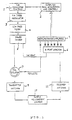
- Figure 1 is a schematic block diagram of an
apparatus to measure unburnt carbon in fly ash according to
a first embodiment of this invention;
- Figure 2 is a schematic diagram of the antennae
and sample measurement chamber in Figure 1 for measurement
in free space;
- Figure 3 is a schematic diagram of the antennae
and sample measurement chamber in Figure 1 for measurement
in a waveguide;
- Figure 4 is a schematic diagram of the antennae
and sample measurement chamber in Figure 1 for measurement
in a microwave resonant cavity;
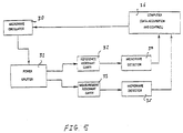
- Figure 5 is a schematic diagram of a further
apparatus to measure unburnt carbon content of fly ash
according to this invention.
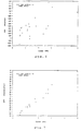
- Figure 6 is a graph showing correlation of (A/W)
with wt% carbon for measurement in a waveguide;
- Figure 7 is a graph showing correlation of (/W)
with wt% carbon for measurement in a waveguide;
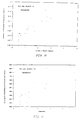
- Figure 8 is a graph showing correlation of (A/W)
with wt% carbon for measurement in free space;
- Figure 9 is a graph showing correlation of (/W)
with wt% carbon for measurement in free space; and
- Figure 10 is a graph showing correlation of
change in resonant frequency with wt% carbon for
measurements in a resonant cavity; and
- Figure 11 is a graph showing correlation of
(change in 1/Q) x fr with wt% carbon for measurements in a
resonant cavity.
-
MODES FOR CARRYING OUT THE INVENTION
-
The propagation of an electromagnetic wave (EM)
in a dielectric medium is described by Maxwell's equations,
and the complex amplitude given by
E(1)=E0 exp (-γ1)
where 1 is the distance travelled by the EM wave in the
dielectric medium from some reference point where its
amplitude was E
0, and γ is the propagation constant of the
wave given by
γ = α + jβ
where α and β are the attenuation and phase constants
respectively. For a non-magnetic dielectric medium α and β
are given by
where ε
0 is permittivity of free space, λ
0 the wavelength in
free space, ε' the dielectric constant of the medium and ε"
the loss factor of the medium. The attenuation constant α
represents the attenuation of the EM wave (in nepers per
metre) and the phase constant β represents the phase shift
of the EM wave (in radians per metre).
-
From equations (3) and (4), it can be seen that
the attenuation and phase shift of an EM wave in a
dielectric is a function of the complex permittivity of the
medium,
ε* = ε' - j ε"
-
For a multicomponent dielectric medium the
complex permittivity may be approximated by
where v
i and ε*
i are the volume fraction and complex
permittivity of the i
th component respectively.
-
When a plane EM wave is incident upon a
dielectric interface, part of it is reflected and part
transmitted. For a non-magnetic dielectric in air the
reflection coefficient, R, and transmission coefficient, T,
are given by
R = ER E0 = 1-ε*/ε0 1+ε*/ε0
T = E T E0 = 1+R
where E0, ER and ET are the incident, reflected and
transmitted electric field vectors. From equations (3) and
(4) it can be seen that the phase shift and attenuation of
a transmitted microwave signal are functions of the
effective complex permittivity of the sample given by
equation (6). For fly ash the complex permittivity of the
unburnt carbon is significantly different from the
remaining matrix which principally comprises oxides of
silicon, aluminium and iron. Therefore the measured
attenuation and phase shift for fly ash are strong
functions of the unburnt carbon shift of a reflected signal
are therefore also functions of the unburnt carbon content
of the samples.
-
For a cylindrical microwave resonant cavity the
resonant frequency of the microwave cavity, f, can be
calculated from,
where 'n,m,l' refer to the particular resonant mode (and
correspond to the number of electric field maxima in the
standing wave pattern , r and z directions), 'a' and 'd'
are the cavity radius and length respectively and ρ is a
constant determined for each resonant mode. For a TM
010
resonant cavity, equation (1) reduces to
ƒ010 = 2.405 c 2Πa
When a sample with permittivity ε* = e' - j" is placed
about the axis of a TM
010 cavity, and the sample radius,
r<<a, it is found that, the change in the resonant
frequency, Δf, and Q-factor,
Δ 1/Q, are related to the
dielectric properties of the sample by,
Δf f = ε'-12 . Vs
where V
s is the volume fraction of the cavity filled by the
sample. Therefore for a constant volume sample, Δf/f is
proportional to ε' and
Δ 1/Q is proportional to ε". It
follows that for measurements on fly ash in such a cavity,
Δf/f and
Δ 1/Q are both strong functions of the weight
percent unburnt carbon in the fly ash. In practice, the
microwave parameters usually measured are the change in
resonant frequency, Δf, and the change in resonant power,
ΔP, and Δ1/Q is a derived parameter.
-
In the method for determining unburnt carbon
content of fly ash according to one aspect of this
invention a microwave signal is directed through a fly ash
sample using suitable transmitting and receiving antennae
and the attenuation and phase shift of the signal due to
the fly ash sample are measured. These are normally
calculated as the difference between the attenuation and
phase shift determined with the sample and air. To
compensate for variation in the density and thickness of
the fly ash sample the phase shift and attenuation can be
normalised to a unit sample mass per unit area. This is
not necessary where the variation in sample density and
thickness can be maintained within acceptable limits by a
suitable sample presentation system.
-
To obtain a measure of unburnt carbon content in
terms of weight percent (wt%) the attenuation or phase
shift data are correlated with wt% unburnt carbon,
determined by standard laboratory analysis, using least
squares regression and equations of the form:
wt% unburnt carbon = a0 + a1 (c)
wt% unburnt carbon = b0 + b1 (Ac)
where c and Ac are the corrected (compensated for variation
in sample density and thickness) phase shift and
attenuation respectively, and a0,..,b1 are fitting
constants. The unburnt carbon content may also be
determined from a combined measurement of attenuation and
phase shift, independent of variation in sample density and
thickness, using an equation of the form
wt% unburnt carbon = C0 + C1(m) + C2(Am)
where m and Am are the measured phase shift and attenuation
respectively, and C0,..,C2 are fitting constants.
-
In the method for determining unburnt carbon
content of fly ash according to another aspect of the
invention a microwave signal is directed at a fly ash
sample and the reflected signal detected. Either a
transceiver or separate transmitting and receiving antennae
can be used for transmitting and receiving the microwave
signal. As with the transmission method the attenuation
and phase shift of the reflected signal are measured and
preferably are correlated with wt% unburnt carbon using
least squares regression and equations of the same form as
(13), (14) and (15).
-
Figure 1 schematically shows the arrangement of
the apparatus to measure unburnt carbon content of fly ash
according to this invention. As shown the apparatus
comprises a microwave source which takes the form of a
Yttrium-Iron-Garnet oscillator 1 tuneable over the range 2
to 4 GHz and controlled by a data logging computer 2. The
output of oscillator 1 is modulated by a PIN diode
modulator 3 and directed through a low pass filter 4 to a
power divider 5. Power divider 5 diverts a small amount of
the microwave signal to an 8-port junction 6 as a reference
signal. The remainder of the microwave signal is directed
via a cirulator 7 to a transmitter antenna 8. Circulator 7
is provided to direct any reflected signal to an
appropriate instrumentation amplifier 9 to provide a
measurement signal for computer 2. Transmitter antenna 8
directs the microwave signal through a sample measurement
chamber 10 to a receiver antenna 11 from which the received
signal is directed to 8-port junction 6 and instrumentation
amplifiers 9 to provide a measure of the attenuation and
phaseshift of the received signal in the known manner.
This data is transmitted for processing in the manner
described herein.
-
The microwave antennae can be of any type
suitable to the selected sample presentation technique.
Figures 2 to 4 show three preferred arrangements of the
antennae and sample measurement chamber.
-
Referring to Figure 2 an arrangement for
measurement on an ash sample in free space. The antennae
are horn antennae 12, 13 and the ash sample 14 is contained
in a container 15 formed of a material such as wood or
plastic which allows the transmission of microwaves. In
this arrangement the ash sample 14 is packed in container
15 and suitably positioned between horns 12, 13. The phase
shift and attenuation are determined as described above and
used to calculate the wt% of unburnt carbon as described
above.
-
Figure 3 shows an arrangement for measurement on
sample in a waveguide. In this arrangement the antennae
are capacitive posts or inductive loops 16,17. The sample
14 to be measured is packed into a section of waveguide 18
of circular or rectangular cross section suited to the
frequency range of the microwave signal. For measurements
in the 2.6 to 3.95 GHz frequency range an RG-48 rectangular
waveguide can be used. The sample is confined to the
selected region of the waveguide by plastic sheets 19 which
allow transmission of the microwave signal. The phase
shift and attenuation are determined as described above and
used to calculate the wt% of unburnt carbon as described
above.
-
Figure 4 shows an arrangement for measurement on
a sample in a microwave resonant cavity. In this
arrangement the ash sample is contained in a nonconducting,
for example, ceramic or plastic tube 20 located
along the axis of a TE or TM mode resonant cavity 21. The
microwave signal is coupled in and out of the resonant
cavity using H-field (inductive loop) probes 22, 23.
-
Figure 5 shows another arrangement for the
measurement of the unburnt carbon content of a fly ash
sample. A variable frequency microwave oscillator 30
provides a microwave signal to a microwave power divider
31. Power divider 31 produces two output signals which are
respectively directed to a reference microwave resonant
cavity 32 and a measurement microwave resonant cavity 33.
The fly ash sample (not shown) is placed in or
appropriately passed through the measurement cavity 33.
Detectors 34 and 35 respectively measure the attenuation of
the microwave signal respectively propogated in the
reference cavity and measurement cavity. Detectors 34 and
35 can be of any suitable known type such as diode
detectors. The outputs of detectors 34, 35 are fed to a
processor 36 which is used to determine a measure of the
resonant frequency, transmitted power at the resonant
frequency, and Q-factor of both cavities from the swept
frequency response (i.e. attenuation) of the received
signal. A measure of weight percent unburnt carbon can
then be provided by the processor as explained by the
following.
-
If the resonant frequency and Q-factor of the
reference cavity are f
r and Q
r respectively, and the
resonant frequency and Q-factor of the measurement cavity
are f
m and Q
m respectively, then the weight percent unburnt
carbon in the fly ash of the sample is determined
substantially independently of the sample bulk density from
a function of the form
where,
Δf = fr - fm
and Δ1/Q is derived from the change in the resonant power
of the cavity and defined by,
Δ1/Q = k.(100.05ΔP-1)
where k is a constant for a particular cavity, and
ΔP = Pm - Pr
where, P
r is the resonant power of the reference cavity
(measured in decibels), and P
m is the resonant power of the
cavity containing the sample (measured in decibels).
Typically
is a correlation function of the form
where a
0, a
1, a
2 ... are fitting constants
or,
wherein b
0, b
1, b
2 ... are fitting constants.
-
The significant advantages of this arrangement
compared to that using a single measurement in a microwave
resonator are that the measured Δf and Δ(1/Q) are
effectively independent of drifts in the microwave
oscillator output frequency due to ambient temperature
variations on drift in the oscillator control voltage.
This is a consequence of the measurement period of the
frequency sweep being much less than the period over which
such drifts normally occur. Therefore using this technique
high measurement accuracy can be achieved without the need
for a highly stabilised microwave source or electronics.
This enables Δf to be determined from measurement of ΔV,
the difference in the control voltage of the microwave
oscillator at fm and fr, rather than from the more
difficult and expensive technique of using a microwave
frequency counter.
-
The measured Δf and Δ(1/Q) are independent of
temperature drift in the microwave detectors, as such drift
only effects the amplitude of the detected microwave
signal. If the reference and measurement cavities are
substantially similar in design and dimension the measured
Δf and Δ(1/Q) are also independent of drifts in the
resonant frequency of the cavities due to metal expansion
with ambient temperature variations. In this arrangement
it is desirable to place a standard absorber in the
reference cavity such that fr is just greater than the
maximum fm that occurs in the particular measurement
application. In this case the swept frequency range, Δf,
is minimised.
-
When the method described above is performed
using a single microwave cavity a reference measurement is
made when the cavity does not contain the sample.
Preferably the period between reference measurements is
substantially shorter than oscillator, electronic and
temperature drifts.
-
The apparatus described with reference to Figures
1 and 2, Figures 1 and 3, and Figures 1 and 4 respectively
were used to perform measurements on a range of fly ash
samples from New South Wales and Queensland power stations.
The unburnt carbon content of these samples was determined
by standard chemical analysis using LECO analyser and was
in the range 0.5 to 13 wt%. For measurement, in free space
and in waveguides the samples were packed in an open
container to a depth of approximately 100mm, and in a 200mm
length of RG-48 waveguide section respectively, and the
phase shift and attenuation of a 3.3 GHz microwave signal
determined. The data were correlated with wt% carbon using
the equations,
wt% carbon = a0 + a1 (fly ash/w)
wt% carbon = b0 + b1 (Afly ash/w)
where a0,...,b1 are fitting constants, w is sample mass per
unit area (in g cm-2) and fly ash and Afly ash are the phase
shift (in degrees) and attenuation (in dB) of the fly ash
sample respectively.
-
The apparatus described with reference to Figure
5 was also used to perform measurements on one of the fly
ash samples. In this case the data were correlated with
wt% carbon using equation 19.
-
R.m.s. errors from correlations on the data using
equations (12) and (13) are given below in Table 1.
| Power Station | Unburnt Carbon (Wt%) | Measurement Geometry | R.m.s. Error (wt% carbon) |
| | | | Equation (21) | Equation (22) | Equation (19) |
| Wallerawang | 3-13 | Free space | 0.41 | 1.41 | - |
| | | Waveguide | 0.28 | 1.22 | - |
| Swanbank | 0.5-5 | Free space | 0.17 | 0.83 | - |
| | | Waveguide | 0.22 | 0.70 | - |
| | | Resonator | - | - | 0.34 |
| Eraring | 0.5-2.5 | Waveguide | 0.19 | 0.29 | - |
-
Plots of the data for Swanbank fly ash samples
are presented in Figures 6 and 7 for measurements in
waveguide and Figures 8 and 9 for measurements in free
space and Figures 10 and 11 for measurements in a
resonator. The r.m.s. errors in Table 1 represent the
total analysis error due to gauge inaccuracy, sampling and
chemical analysis. These results indicate that a
measurement of phase shift or the resonator characteristics
is the most accurate for the determination of carbon
content, and the accuracy of analysis is comparable to or
better than that obtained with previous methods.
-
The apparatus described above is particularly
suitable for on-line analysis of the unburnt carbon content
of fly ash sampled from a boiler outlet duct. Fly ash is
removed from the boiler outlet duct by conventional
sampling means (not shown), for example using a Cegrit
sample and cyclone, and passed through the sample
measurement chamber of the apparatus. The fly ash can be
fed continuously or in batches, and carried to and from the
measurement chamber by any suitable means, for example by a
screw conveyor.
-
The foregoing describes the invention with
reference to some specific examples and it will be apparent
to those skilled in the art that modifications can be made
without departing from the scope of the invention.


 where ε0 is permittivity of free space, λ0 the wavelength in free space, ε' the dielectric constant of the medium and ε" the loss factor of the medium. The attenuation constant α represents the attenuation of the EM wave (in nepers per metre) and the phase constant β represents the phase shift of the EM wave (in radians per metre).


 and Δ1/Q is derived from the change in the resonant power of the cavity and defined by,
 is a correlation function of the form
 where a0, a1, a2 ... are fitting constants
