EP0940588B1 - Pièce de liaison entre deux poutrelles qui y sont coulissables - Google Patents
Pièce de liaison entre deux poutrelles qui y sont coulissables Download PDFInfo
- Publication number
- EP0940588B1 EP0940588B1 EP98440041A EP98440041A EP0940588B1 EP 0940588 B1 EP0940588 B1 EP 0940588B1 EP 98440041 A EP98440041 A EP 98440041A EP 98440041 A EP98440041 A EP 98440041A EP 0940588 B1 EP0940588 B1 EP 0940588B1
- Authority
- EP
- European Patent Office
- Prior art keywords
- connecting piece
- slide
- office furniture
- jaw
- small
- Prior art date
- Legal status (The legal status is an assumption and is not a legal conclusion. Google has not performed a legal analysis and makes no representation as to the accuracy of the status listed.)
- Expired - Lifetime
Links
- 230000008878 coupling Effects 0.000 abstract 3
- 238000010168 coupling process Methods 0.000 abstract 3
- 238000005859 coupling reaction Methods 0.000 abstract 3
- 230000000903 blocking effect Effects 0.000 description 7
- 238000006073 displacement reaction Methods 0.000 description 4
- 238000000926 separation method Methods 0.000 description 4
- 238000009434 installation Methods 0.000 description 2
- 238000004519 manufacturing process Methods 0.000 description 2
- 238000012986 modification Methods 0.000 description 2
- 230000004048 modification Effects 0.000 description 2
- 230000000694 effects Effects 0.000 description 1
- 238000011065 in-situ storage Methods 0.000 description 1
- 210000000056 organ Anatomy 0.000 description 1
- 238000005192 partition Methods 0.000 description 1
- 210000003813 thumb Anatomy 0.000 description 1
Images


Classifications
-
- F—MECHANICAL ENGINEERING; LIGHTING; HEATING; WEAPONS; BLASTING
- F16—ENGINEERING ELEMENTS AND UNITS; GENERAL MEASURES FOR PRODUCING AND MAINTAINING EFFECTIVE FUNCTIONING OF MACHINES OR INSTALLATIONS; THERMAL INSULATION IN GENERAL
- F16B—DEVICES FOR FASTENING OR SECURING CONSTRUCTIONAL ELEMENTS OR MACHINE PARTS TOGETHER, e.g. NAILS, BOLTS, CIRCLIPS, CLAMPS, CLIPS OR WEDGES; JOINTS OR JOINTING
- F16B12/00—Jointing of furniture or the like, e.g. hidden from exterior
- F16B12/10—Jointing of furniture or the like, e.g. hidden from exterior using pegs, bolts, tenons, clamps, clips, or the like
- F16B12/28—Jointing of furniture or the like, e.g. hidden from exterior using pegs, bolts, tenons, clamps, clips, or the like for metal furniture parts
- F16B12/32—Jointing of furniture or the like, e.g. hidden from exterior using pegs, bolts, tenons, clamps, clips, or the like for metal furniture parts using clamps, clips, wedges, sliding bolts, or the like
-
- A—HUMAN NECESSITIES
- A47—FURNITURE; DOMESTIC ARTICLES OR APPLIANCES; COFFEE MILLS; SPICE MILLS; SUCTION CLEANERS IN GENERAL
- A47B—TABLES; DESKS; OFFICE FURNITURE; CABINETS; DRAWERS; GENERAL DETAILS OF FURNITURE
- A47B17/00—Writing-tables
- A47B17/03—Writing-tables with substantially horizontally extensible or adjustable parts other than drawers, e.g. leaves
- A47B17/033—Writing-tables with substantially horizontally extensible or adjustable parts other than drawers, e.g. leaves with parts added to the original furniture to enlarge its surface
-
- F—MECHANICAL ENGINEERING; LIGHTING; HEATING; WEAPONS; BLASTING
- F16—ENGINEERING ELEMENTS AND UNITS; GENERAL MEASURES FOR PRODUCING AND MAINTAINING EFFECTIVE FUNCTIONING OF MACHINES OR INSTALLATIONS; THERMAL INSULATION IN GENERAL
- F16B—DEVICES FOR FASTENING OR SECURING CONSTRUCTIONAL ELEMENTS OR MACHINE PARTS TOGETHER, e.g. NAILS, BOLTS, CIRCLIPS, CLAMPS, CLIPS OR WEDGES; JOINTS OR JOINTING
- F16B12/00—Jointing of furniture or the like, e.g. hidden from exterior
- F16B12/40—Joints for furniture tubing
Definitions
- the present invention relates to a connecting piece between two beams belonging to a structure used in particular in the office furniture. More specifically, it applies to modular offices according to multiple configurations at the discretion of the individual user or designer workspaces such as collective landscaped offices (DE 41 27 127 A).
- Said elements are in particular beams, crosspieces, columns and balusters generically constituting a set of beams fixed to each other and to the legs, and making the aforementioned frame or structure, to which the elements are fixed more directly functional for the user.
- connecting pieces are then visible and without functional allocation, and have a negative effect on the overall aesthetics. They are also arranged in a fixed manner with respect to the structure, and do not allow general that modifications limited by adding elements according to configurations originally planned and necessarily limited in number.
- the present invention which applies for example to the fixing of vertical separation panels on structures supporting planes of horizontal work, overcomes these disadvantages.
- a connecting piece between two beams of a structure also applicable to modular office furniture according to multiple configurations, in particular likely to include vertical panels and horizontal, and it allows on the one hand a translative displacement by sliding of each beam relative to said connecting piece and on the other hand its fixing at any relative positioning point.
- the sliding means by compared to one of the two beams consist of a width slide variable with closed configuration of minimum width corresponding to the adjustment of said beam in the slide and a open configuration of maximum width allowing the release of the beam
- said connecting piece comprising means for blocking the configuration of the slide in any width between said minimum and maximum values, and a recall mechanism bringing back the slide to its minimum width configuration in the absence of blockage.
- the slide of variable width allows the attachment of the connecting piece, in the manner of a clamp, to any beam, spar, crosspiece, etc ... of shape corresponding to that of the slide in position closed, whether these are already integrated into a functional structure or not.
- the attachment is easy to the user, achievable without tools in anywhere in the beam, which gives the joint flexibility exceptional use compared to what existed until now, in particular for a configuration of furniture already in position.
- the translational displacement relative to the second beam is made using a male element or slide arranged at the end of a member mechanically connected to said connecting piece, which cooperates with a slide made in said second beam,
- This member provided with the male element is moreover mobile in translation rectilinear with respect to said connecting piece, the rectilinear displacement being constituting the blocking / unblocking of said second beam relative to the connecting piece by tightening / loosening their contact surfaces respective, caused by the approximation / distancing of the male element and the connecting piece.
- the blocking / unblocking is for example carried out by bolting of the member provided with the male element in the connecting piece, the realization of the tightening / loosening being possible from the inside only when the slide of variable width does not accommodate a beam.
- the mounting of additional elements using the connecting piece according to the invention implies a particular assembly order, which does not constitute however not an obstacle to the ease of implementation of the modifications desired, but is common sense. Indeed, it is better to proceed to adjustment of the relative positioning of the connecting piece / baluster before install it on the pre-existing structure, because this set works almost always in pairs, and that the adjustment of the two individuals of each pair would be much more problematic after their installation, when they are distance from each other.
- the slide of variable width has a fixed jaw and a movable jaw, the latter sliding in the fixed jaw according to a stroke in particular limited by the locking means.
- the movable jaw has a first part constituting on the one hand a transverse portion of the slide, and configured to adapt to a corresponding transverse portion of a beam, and on the other hand a connecting surface with a second part forming a drawer sliding in a fixed jaw housing.
- the sliding drawer has a U-shaped section to curved base, said base comprising means for attaching an element also attached to the fixed jaw, and means of connection to blocking means.
- the connecting piece when assembled, comprises a unit aesthetics achieved by the two jaws, especially when they are in closed position.
- the fixed jaw housing intended to receive said jaw drawer mobile comprises at least one flat surface with a shape parallel to the base of the U, located on a ramp on the face of said housing opposite the base of the housing and oriented towards it, said base further comprising a light extending in the direction of the axis of movement of the movable jaw relative to the fixed jaw, and a means for hooking the element of reminder.
- These means for locking the jaws relative to each other are operable manually and consist of a wheel fixed to a threaded rod free to rotate in an opening in the drawer of the movable jaw, and cooperating with a nut arranged in a drawer housing, the flat end of said threaded rod applying at the time of blocking against said surface plane fitted to the ramp of the fixed jaw.
- the longitudinal light provided in the base of the housing allows the wheel to meet no obstacle during tightening that could inhibit the pressure that the flat end of the rod must exert on the surface plane of said ramp to achieve effective locking.
- the return element is a spring traction fixed at its two ends to the hooking means provided under form of hooks in the fixed jaw and in the movable jaw.
- the wheel is opened to reach the unlocking position, we spread the jaws so as to insert the beam and we release the movable jaw which replaces itself automatically, due to the means of reminder, in contact with the fixed jaw, clamp closed.
- the return spring also causes the automatic closing of the jaws, and it then suffices to tighten the locking means so that the connection is carried out.
- the installation of a separation panel is done as follows: the operator installs a first pair of clamp / baluster at a location deemed then fix the second at a distance approximately equal to the panel length.
- the operator can at any time adjust the relative positioning of the clamps, and consequently balusters, by simply releasing the jaws, which are then moved aside and moved along the beam.
- the movement of an entire panel by a single operator can be made by successively sliding a first clamp whose associated column was disengaged from the panel, then sliding of the remains before reattaching the panel to the first column.
- Two operators can of course, by simultaneously unlocking the two jaws, achieve displacement of the whole in a single operation.
- the clamp (P) appearing in FIG. 1 is made up of a pair of jaws (1) and (2) having a single degree of freedom, one with respect to the other: the jaw (1) can move away from the jaw (2), and they are by therefore called movable jaw (1) and fixed jaw (2).
- the clamp (P) secured to a column (C) fits on the partially visible desk frame, to a side member (L) of the structure supporting a work plan (T).
- the spar (L) in this case has a oblong section, hence the corresponding shape of the slide formed between the movable jaw (1) and the fixed jaw (2).
- the locking means are manual, for example consisting of a wheel (4) fixed to a threaded rod, allow relative movement, and therefore the clamping function of the jaws (1, 2).
- the threaded rod cooperates with a nut located in a housing (9) of the drawer.
- the balusters (C) have axial slides (5) shown on their periphery, housing and guiding a male element or slide of an organ attached to the clamp (P). Blocking / unblocking of this link is not possible as in the situation of FIG. 1, because access to the control means of this connection is made via the slide formed between the jaws (1) and (2), as we will see below.
- Figure 4 shows in detail the configuration of the movable jaw (1) object from the example described. It has two main parts: an envelope external (6) delimiting on the one hand, in its upper zone (7), a portion transverse of the slide, and on the other hand a surface (8) which may be located proximity of the other portion of slide carried by the fixed jaw (2), and forming the connection with the base of a U-shaped drawer (3) defining a hollow volume, curved base (10) comprising a hook (11) intended to receive the end of a tension spring (not shown), as well as the housing (9) receiving the locking means bolt.
- an envelope external (6) delimiting on the one hand, in its upper zone (7), a portion transverse of the slide, and on the other hand a surface (8) which may be located proximity of the other portion of slide carried by the fixed jaw (2), and forming the connection with the base of a U-shaped drawer (3) defining a hollow volume, curved base (10) comprising a hook (11) intended to receive the end of a tension spring (not shown), as well as
- the side walls (12, 13) of the drawer (3) constitute, via their extension in the upper area (7) of the outer casing (6) of the slide, stiffening ribs of the movable jaw (1).
- the fixed jaw (2) appears in detail in Figure 5.
- the housing (14) of the drawer (3) has a shape allowing the latter to adjust to it. It also includes a projection or ramp (15) with a flat surface oriented towards the base (16) of the housing, which comprises a light (17) allowing in particular the passage of the threaded rod fixed to the locking / unlocking wheel (4).
- the area (18) located immediately above the housing (14) constitutes the second transverse portion of the slide.
- the contact surface (19) constituting the extreme edge of the jaw fixed (2) can be located, depending on the section of the beam (L), near the homologous surface (8) of the movable jaw (1), during the approximation jaws (1) and (2) around the beam (L).
- the arm (20) extending this transverse portion (18) of slide has one end (21) delimiting in volume a portion of cylinder, allowing to accommodate the baluster (C).
- the threaded hole (22) allows the passage of a threaded rod of the bolt (not shown) allowing clamping of the baluster (C) in the portion cylindrical (21) of the end of the arm (20), in particular using the part male inserted in the slides (5) of said baluster (C).
- This male part forms the opposite end to the bolted threaded rod of the connecting member mechanical connecting the fixed jaw (2) and the baluster (C).
- Figure 6 again showing the fixed jaw (2), in section longitudinal, specifies the relative arrangement of the elements functional components.
- the hook (23) allowing the attachment of the end of a conventional tension spring (not shown) appears, and the shape of the transverse portion of slide is specified.
- the longitudinal member (L) being oblong, the shape of the slide, in cross section, comprises a horizontal zone (24) carried by the fixed jaw (2).
- This horizontal area can be widened if the movable jaw (1) is locked in the spread position, for example if the oblong spar is wider.
- the U-shaped drawer (3) of the movable jaw (1) can slide in the housing (14).
- the spring (not shown) recalls said jaw mobile (1) towards its closed position for example in contact with the fixed jaw (2).
- This connecting piece (P) considerably facilitates the mounting of the vertical elements like partition panels, and makes it possible even on an already assembled structure.
Landscapes
- Engineering & Computer Science (AREA)
- General Engineering & Computer Science (AREA)
- Mechanical Engineering (AREA)
- Furniture Connections (AREA)
- Handcart (AREA)
- Fittings On The Vehicle Exterior For Carrying Loads, And Devices For Holding Or Mounting Articles (AREA)
- Non-Reversible Transmitting Devices (AREA)
- Clamps And Clips (AREA)
- Gripping Jigs, Holding Jigs, And Positioning Jigs (AREA)
- Mutual Connection Of Rods And Tubes (AREA)
- Hinge Accessories (AREA)
- Hinges (AREA)
Description
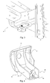
- la figure 1 représente une pièce de liaison ou pince selon l'invention ;
- la figure 2 montre ladite pièce en phase d'accrochage à un longeron supportant un plan de travail ;
- la figure 3 est similaire à la précédente, la fixation étant réalisée ;
- la figure 4 est une vue en perspective de la mâchoire mobile ;
- la figure 5 est une vue en perspective de la mâchoire fixe ;
- la figure 6 montre en coupe longitudinale de la mâchoire fixe.
Claims (10)
- Pièce de liaison (P) entre deux poutrelles (L, C) d'une structure de type applicable à du mobilier de bureau modulable suivant de multiples configurations et notamment susceptible de comporter des panneaux verticaux et horizontaux (T), ladite pièce (P) permettant un déplacement translatif par coulissement de chaque poutrelle (L, C) et sa fixation en tout point de positionnement relatif,
caractérisée en ce que les moyens de coulissement par rapport à l'une des deux poutrelles (L) sont constitués d'une glissière de largeur variable présentant une configuration fermée de largeur minimale correspondant à l'ajustement de ladite poutrelle (L) dans la glissière et une configuration ouverte de largeur maximale permettant la libération de la poutrelle (L), ladite pièce de liaison (P) comportant des moyens de blocage (4) de la configuration de la glissière en n'importe quelle largeur comprise entre lesdites valeurs minimale et maximale, et un mécanisme de rappel ramenant la glissière à sa configuration de largeur minimale en l'absence de blocage. - Pièce de liaison (P) entre deux poutrelles (L, C) d'une structure de type applicable à du mobilier de bureau selon la revendication 1, caractérisée en ce que le déplacement translatif par rapport à la seconde poutrelle (C) est réalisé à l'aide d'un élément mâle ou coulisseau disposé à l'extrémité d'un organe relié mécaniquement à ladite pièce de liaison (P), qui coopère avec une glissière (5) pratiquée dans ladite seconde poutrelle (C).
- Pièce de liaison (P) entre deux poutrelles (L, C) d'une structure de type applicable à du mobilier de bureau selon la revendication 2, caractérisée en ce que ledit élément mâle ou coulisseau est mobile en translation rectiligne par rapport à ladite pièce de liaison (P), le déplacement rectiligne étant constitutif du blocage / déblocage de ladite seconde poutrelle (C) par rapport à la pièce de liaison (P) par serrage / desserrage de leurs surfaces de contact, provoqué par le rapprochement / éloignement de l'élément mâle ou coulisseau et de la pièce de liaison (P).
- Pièce de liaison (P) entre deux poutrelles (L, C) d'une structure de type applicable à du mobilier de bureau selon la revendication 3, caractérisée en ce que le blocage/déblocage est réalisé par boulonnage de l'organe muni de l'élément mâle ou coulisseau dans la pièce de liaison (P), la réalisation du serrage/desserrage étant possible depuis l'intérieur de celle-ci uniquement lorsque la glissière de largeur variable ne loge pas de poutrelle (L).
- Pièce de liaison (P) entre deux poutrelles (L, C) d'une structure de type applicable à du mobilier de bureau selon l'une quelconque des revendications précédentes, caractérisée en ce que la glissière de largeur variable comporte une mâchoire fixe (2) et une mâchoire mobile (1), cette dernière coulissant dans la mâchoire fixe (2) selon une course notamment limitée par les moyens de blocage (4).
- Pièce de liaison (P) entre deux poutrelles (L, C) d'une structure de type applicable à du mobilier de bureau selon la revendication précédente, caractérisée en ce que la mâchoire mobile (1) comporte une première partie (6) constituant d'une part une portion transversale de la glissière (7), et configurée pour s'adapter à une portion transversale correspondante d'une poutrelle (L), et d'autre part une surface (8) pouvant se situer à proximité d'une surface homologue (19) de la portion transversale résiduelle (18) de la glissière portée par la mâchoire fixe (2), ladite surface (8) étant reliée à une seconde partie formant tiroir coulissant (3) dans un logement (14) de ladite mâchoire fixe (2).
- Pièce de liaison (P) entre deux poutrelles (L, C) d'une structure de type applicable à du mobilier de bureau selon la revendication précédente, caractérisée en ce que ledit tiroir coulissant (3) présente une section en forme de U à base incurvée (10), ladite base (10) comportant un moyen d'accrochage (11) d'un élément de rappel également fixé à la mâchoire fixe et des moyens de liaison (9) aux moyens de blocage (4).
- Pièce de liaison (P) entre deux poutrelles (L, C) d'une structure de type applicable à du mobilier de bureau selon l'une des revendications 6 et 7, caractérisée en ce que le logement (14) de la mâchoire fixe (2) destiné à recevoir ledit tiroir (3) de la mâchoire mobile (1) comporte au moins une rampe avec une surface plane (15) d'allure parallèle à la base (10) du U, localisée sur la face dudit logement (14) opposée à ladite base (10) et orientée vers elle, la base du logement (16) comportant au surplus une lumière (17) s'étendant dans la direction du mouvement de la mâchoire mobile (1) relativement à la mâchoire fixe (2), et un moyen d'accrochage (23) de l'élément de rappel.
- Pièce de liaison (P) entre deux poutrelles (L, C) d'une structure de type applicable à du mobilier de bureau selon la revendication précédente, caractérisée en ce que les moyens de blocage (4) des mâchoires (1, 2) l'une relativement à l'autre sont opérables manuellement et consistent en une molette (4) fixée à une tige filetée libre en rotation dans un orifice pratiqué dans le tiroir (3) de la mâchoire mobile (1), et coopérant avec un écrou disposé dans un logement (9) dudit tiroir, l'extrémité plane de ladite tige filetée s'appliquant au moment du blocage contre la surface plane (15) équipant le logement (14) de la mâchoire fixe (2).
- Pièce de liaison (P) entre deux poutrelles (L, C) d'une structure de type applicable à du mobilier de bureau selon l'une des revendications 7 à 9, caractérisée en ce que l'élément de rappel est un ressort de traction fixé à ses deux extrémités aux moyens d'accrochage prévus sous forme de crochets (23, 11) dans la mâchoire fixe (2) et dans la mâchoire mobile (1).
Priority Applications (4)
| Application Number | Priority Date | Filing Date | Title |
|---|---|---|---|
| AT98440041T ATE198226T1 (de) | 1998-03-02 | 1998-03-02 | Verbindungsstück für zwei darin bewegbare trägerprofile |
| EP98440041A EP0940588B1 (fr) | 1998-03-02 | 1998-03-02 | Pièce de liaison entre deux poutrelles qui y sont coulissables |
| ES98440041T ES2152742T3 (es) | 1998-03-02 | 1998-03-02 | Pieza de union entre dos viguetas deslizables en la misma. |
| DE69800441T DE69800441T2 (de) | 1998-03-02 | 1998-03-02 | Verbindungsstück für zwei darin bewegbare Trägerprofile |
Applications Claiming Priority (1)
| Application Number | Priority Date | Filing Date | Title |
|---|---|---|---|
| EP98440041A EP0940588B1 (fr) | 1998-03-02 | 1998-03-02 | Pièce de liaison entre deux poutrelles qui y sont coulissables |
Publications (2)
| Publication Number | Publication Date |
|---|---|
| EP0940588A1 EP0940588A1 (fr) | 1999-09-08 |
| EP0940588B1 true EP0940588B1 (fr) | 2000-12-20 |
Family
ID=8235662
Family Applications (1)
| Application Number | Title | Priority Date | Filing Date |
|---|---|---|---|
| EP98440041A Expired - Lifetime EP0940588B1 (fr) | 1998-03-02 | 1998-03-02 | Pièce de liaison entre deux poutrelles qui y sont coulissables |
Country Status (4)
| Country | Link |
|---|---|
| EP (1) | EP0940588B1 (fr) |
| AT (1) | ATE198226T1 (fr) |
| DE (1) | DE69800441T2 (fr) |
| ES (1) | ES2152742T3 (fr) |
Families Citing this family (4)
| Publication number | Priority date | Publication date | Assignee | Title |
|---|---|---|---|---|
| DE102005027386A1 (de) * | 2005-06-14 | 2006-12-21 | Korb & Korb Innenarchitektur Und Design | Tisch mit einklappbaren Beinpaaren |
| US8132371B2 (en) | 2006-04-14 | 2012-03-13 | Knoll International, S.P.A. | Modular furniture system |
| DE102010060191A1 (de) | 2010-01-18 | 2011-07-21 | Karl Kilpper GmbH kalo-Sitzmöbelfabrik, 71287 | Tisch mit einklappbaren Tischbeinen |
| CN103068278A (zh) | 2010-06-08 | 2013-04-24 | 诺尔公司 | 家具部件紧固装置、家具系统和组装用于工作空间的家具的方法 |
Family Cites Families (3)
| Publication number | Priority date | Publication date | Assignee | Title |
|---|---|---|---|---|
| FR1526947A (fr) * | 1966-12-15 | 1968-05-31 | Cie De Realisations Ind Et Tec | Dispositif d'assemblage de profilés |
| FR2497885A1 (fr) * | 1981-01-09 | 1982-07-16 | Nemoz Jean Claude | Assemblage de tubes |
| DE4127127C2 (de) * | 1991-08-16 | 1994-07-07 | Huelsta Werke Huels Kg | Anbauelement für Möbel |
-
1998
- 1998-03-02 DE DE69800441T patent/DE69800441T2/de not_active Expired - Fee Related
- 1998-03-02 EP EP98440041A patent/EP0940588B1/fr not_active Expired - Lifetime
- 1998-03-02 AT AT98440041T patent/ATE198226T1/de not_active IP Right Cessation
- 1998-03-02 ES ES98440041T patent/ES2152742T3/es not_active Expired - Lifetime
Also Published As
| Publication number | Publication date |
|---|---|
| DE69800441D1 (de) | 2001-01-25 |
| ES2152742T3 (es) | 2001-02-01 |
| EP0940588A1 (fr) | 1999-09-08 |
| ATE198226T1 (de) | 2001-01-15 |
| DE69800441T2 (de) | 2001-07-12 |
Similar Documents
| Publication | Publication Date | Title |
|---|---|---|
| EP0940588A1 (fr) | Pièce de liaison entre deux poutrelles qui y sont coulissables | |
| FR2471793A1 (fr) | Dispositif de blocage d'une extremite d'une ceinture de securite pour vehicules automobiles, combine avec une glissiere d'un siege | |
| FR3090807A1 (fr) | Systeme de connexion et pergola comprenant ledit systeme de connexion | |
| EP0098257A2 (fr) | Ferrures formant articulation pour battants tels que volets, portes ou analogues | |
| EP2343432A2 (fr) | Ensemble de guidage latéral de tablier coulissant | |
| EP1744427B1 (fr) | Coffret pour appareillages électriques à profondeur variable | |
| FR3033357A1 (fr) | Ouvrant, tel qu'une porte de placard, comprenant des dispositifs de pivotement inferieur et superieur, et ensemble correspondant | |
| EP0337845A1 (fr) | Elément de fixation pour assemblage de profilés en structures multidimentionnelles | |
| FR2547852A1 (fr) | Dispositif permettant de regler et de bloquer l'ouverture d'un volet battant d'une baie | |
| FR2915227A1 (fr) | Ensemble de poignee exterieure de porte de vehicule automobile. | |
| EP0407319B1 (fr) | Palier intermédiaire pour fenêtre, porte ou analogue | |
| FR2585756A1 (fr) | Dispositif de jonction entre boitier et prolongateur de cremone a tetiere et a tringles | |
| FR3031541A1 (fr) | Dispositif de serrage d'une entretoise, systeme d'interconnexion de panneaux avec un tel dispositif, coffrage et element de coffrage | |
| EP0651111B1 (fr) | Dispositif de montage et de fixation d'une lisse de garde-corps | |
| FR3065246B1 (fr) | Dispositif d'articulation pour battant | |
| WO2024150108A1 (fr) | Système de rambarde | |
| EP2824785B1 (fr) | Ensemble articulé d un boîtier pour appareillage électrique et boîte de sol comprenant un tel ensemble | |
| EP2320532B1 (fr) | Dispositif de montage d'un montant de châssis sur le fond d'un coffret électrique et coffret électrique comprenant un tel dispositif | |
| FR2516966A1 (fr) | Dispositif pour la fixation d'elements de revetement a une paroi d'une construction | |
| EP1199009B1 (fr) | Pince de fixation d'une structure d'allure verticale à un plateau horizontal | |
| FR2946709A1 (fr) | Dispositif de liaison entre un panneau et un support et ensemble forme par un panneau equipe dudit dispositif et d'un support associe | |
| FR2667382A1 (fr) | Entretoise pour chassis de classement mobile pour dossiers suspendus et chassis la comprenant. | |
| FR2850989A1 (fr) | Systeme d'assemblage de cloisons par rapprochement lateral des panneaux constitutifs | |
| FR2753733A1 (fr) | Dispositif de montage et d'immobilisation d'un poteau de support creux pour cloison interieure d'un local | |
| FR2752866A1 (fr) | Serrure encastrable, notamment dans un montant de coulissant ou de dormant |
Legal Events
| Date | Code | Title | Description |
|---|---|---|---|
| PUAI | Public reference made under article 153(3) epc to a published international application that has entered the european phase |
Free format text: ORIGINAL CODE: 0009012 |
|
| 17P | Request for examination filed |
Effective date: 19980316 |
|
| AK | Designated contracting states |
Kind code of ref document: A1 Designated state(s): AT BE CH DE DK ES FI FR GB GR IE IT LI LU MC NL PT SE |
|
| AX | Request for extension of the european patent |
Free format text: AL;LT;LV;MK;RO;SI |
|
| GRAG | Despatch of communication of intention to grant |
Free format text: ORIGINAL CODE: EPIDOS AGRA |
|
| AKX | Designation fees paid |
Free format text: AT BE CH DE DK ES FI FR GB GR IE IT LI LU MC NL PT SE |
|
| GRAG | Despatch of communication of intention to grant |
Free format text: ORIGINAL CODE: EPIDOS AGRA |
|
| GRAH | Despatch of communication of intention to grant a patent |
Free format text: ORIGINAL CODE: EPIDOS IGRA |
|
| 17Q | First examination report despatched |
Effective date: 20000510 |
|
| GRAH | Despatch of communication of intention to grant a patent |
Free format text: ORIGINAL CODE: EPIDOS IGRA |
|
| GRAA | (expected) grant |
Free format text: ORIGINAL CODE: 0009210 |
|
| AK | Designated contracting states |
Kind code of ref document: B1 Designated state(s): AT BE CH DE DK ES FI FR GB GR IE IT LI LU MC NL PT SE |
|
| PG25 | Lapsed in a contracting state [announced via postgrant information from national office to epo] |
Ref country code: SE Free format text: THE PATENT HAS BEEN ANNULLED BY A DECISION OF A NATIONAL AUTHORITY Effective date: 20001220 Ref country code: IE Free format text: LAPSE BECAUSE OF FAILURE TO SUBMIT A TRANSLATION OF THE DESCRIPTION OR TO PAY THE FEE WITHIN THE PRESCRIBED TIME-LIMIT Effective date: 20001220 Ref country code: FI Free format text: LAPSE BECAUSE OF FAILURE TO SUBMIT A TRANSLATION OF THE DESCRIPTION OR TO PAY THE FEE WITHIN THE PRESCRIBED TIME-LIMIT Effective date: 20001220 Ref country code: AT Free format text: LAPSE BECAUSE OF FAILURE TO SUBMIT A TRANSLATION OF THE DESCRIPTION OR TO PAY THE FEE WITHIN THE PRESCRIBED TIME-LIMIT Effective date: 20001220 |
|
| REF | Corresponds to: |
Ref document number: 198226 Country of ref document: AT Date of ref document: 20010115 Kind code of ref document: T |
|
| ITF | It: translation for a ep patent filed | ||
| REG | Reference to a national code |
Ref country code: CH Ref legal event code: EP |
|
| REG | Reference to a national code |
Ref country code: IE Ref legal event code: FG4D Free format text: FRENCH |
|
| REF | Corresponds to: |
Ref document number: 69800441 Country of ref document: DE Date of ref document: 20010125 |
|
| REG | Reference to a national code |
Ref country code: ES Ref legal event code: FG2A Ref document number: 2152742 Country of ref document: ES Kind code of ref document: T3 |
|
| GBT | Gb: translation of ep patent filed (gb section 77(6)(a)/1977) |
Effective date: 20010126 |
|
| PG25 | Lapsed in a contracting state [announced via postgrant information from national office to epo] |
Ref country code: LU Free format text: LAPSE BECAUSE OF NON-PAYMENT OF DUE FEES Effective date: 20010302 |
|
| PG25 | Lapsed in a contracting state [announced via postgrant information from national office to epo] |
Ref country code: PT Free format text: LAPSE BECAUSE OF FAILURE TO SUBMIT A TRANSLATION OF THE DESCRIPTION OR TO PAY THE FEE WITHIN THE PRESCRIBED TIME-LIMIT Effective date: 20010320 Ref country code: DK Free format text: LAPSE BECAUSE OF FAILURE TO SUBMIT A TRANSLATION OF THE DESCRIPTION OR TO PAY THE FEE WITHIN THE PRESCRIBED TIME-LIMIT Effective date: 20010320 |
|
| PG25 | Lapsed in a contracting state [announced via postgrant information from national office to epo] |
Ref country code: GR Free format text: LAPSE BECAUSE OF FAILURE TO SUBMIT A TRANSLATION OF THE DESCRIPTION OR TO PAY THE FEE WITHIN THE PRESCRIBED TIME-LIMIT Effective date: 20010323 |
|
| PG25 | Lapsed in a contracting state [announced via postgrant information from national office to epo] |
Ref country code: MC Free format text: LAPSE BECAUSE OF NON-PAYMENT OF DUE FEES Effective date: 20010331 |
|
| PLBE | No opposition filed within time limit |
Free format text: ORIGINAL CODE: 0009261 |
|
| STAA | Information on the status of an ep patent application or granted ep patent |
Free format text: STATUS: NO OPPOSITION FILED WITHIN TIME LIMIT |
|
| REG | Reference to a national code |
Ref country code: IE Ref legal event code: FD4D |
|
| 26N | No opposition filed | ||
| REG | Reference to a national code |
Ref country code: GB Ref legal event code: IF02 |
|
| PGFP | Annual fee paid to national office [announced via postgrant information from national office to epo] |
Ref country code: BE Payment date: 20020318 Year of fee payment: 5 |
|
| PGFP | Annual fee paid to national office [announced via postgrant information from national office to epo] |
Ref country code: GB Payment date: 20020321 Year of fee payment: 5 |
|
| PGFP | Annual fee paid to national office [announced via postgrant information from national office to epo] |
Ref country code: ES Payment date: 20020325 Year of fee payment: 5 |
|
| PGFP | Annual fee paid to national office [announced via postgrant information from national office to epo] |
Ref country code: FR Payment date: 20020326 Year of fee payment: 5 |
|
| PG25 | Lapsed in a contracting state [announced via postgrant information from national office to epo] |
Ref country code: LI Free format text: LAPSE BECAUSE OF NON-PAYMENT OF DUE FEES Effective date: 20020331 Ref country code: CH Free format text: LAPSE BECAUSE OF NON-PAYMENT OF DUE FEES Effective date: 20020331 |
|
| PGFP | Annual fee paid to national office [announced via postgrant information from national office to epo] |
Ref country code: NL Payment date: 20020331 Year of fee payment: 5 |
|
| PGFP | Annual fee paid to national office [announced via postgrant information from national office to epo] |
Ref country code: DE Payment date: 20020430 Year of fee payment: 5 |
|
| REG | Reference to a national code |
Ref country code: CH Ref legal event code: PL |
|
| PG25 | Lapsed in a contracting state [announced via postgrant information from national office to epo] |
Ref country code: GB Free format text: LAPSE BECAUSE OF NON-PAYMENT OF DUE FEES Effective date: 20030302 |
|
| PG25 | Lapsed in a contracting state [announced via postgrant information from national office to epo] |
Ref country code: ES Free format text: LAPSE BECAUSE OF NON-PAYMENT OF DUE FEES Effective date: 20030303 |
|
| PG25 | Lapsed in a contracting state [announced via postgrant information from national office to epo] |
Ref country code: BE Free format text: LAPSE BECAUSE OF NON-PAYMENT OF DUE FEES Effective date: 20030331 |
|
| BERE | Be: lapsed |
Owner name: S.A. *STEELCASE STRAFOR Effective date: 20030331 |
|
| PG25 | Lapsed in a contracting state [announced via postgrant information from national office to epo] |
Ref country code: NL Free format text: LAPSE BECAUSE OF NON-PAYMENT OF DUE FEES Effective date: 20031001 Ref country code: DE Free format text: LAPSE BECAUSE OF NON-PAYMENT OF DUE FEES Effective date: 20031001 |
|
| GBPC | Gb: european patent ceased through non-payment of renewal fee | ||
| PG25 | Lapsed in a contracting state [announced via postgrant information from national office to epo] |
Ref country code: FR Free format text: LAPSE BECAUSE OF NON-PAYMENT OF DUE FEES Effective date: 20031127 |
|
| NLV4 | Nl: lapsed or anulled due to non-payment of the annual fee |
Effective date: 20031001 |
|
| REG | Reference to a national code |
Ref country code: FR Ref legal event code: ST |
|
| REG | Reference to a national code |
Ref country code: ES Ref legal event code: FD2A Effective date: 20030303 |
|
| PG25 | Lapsed in a contracting state [announced via postgrant information from national office to epo] |
Ref country code: IT Free format text: LAPSE BECAUSE OF NON-PAYMENT OF DUE FEES Effective date: 20050302 |