EP0940587B1 - Fastening device - Google Patents
Fastening device Download PDFInfo
- Publication number
- EP0940587B1 EP0940587B1 EP19990102434 EP99102434A EP0940587B1 EP 0940587 B1 EP0940587 B1 EP 0940587B1 EP 19990102434 EP19990102434 EP 19990102434 EP 99102434 A EP99102434 A EP 99102434A EP 0940587 B1 EP0940587 B1 EP 0940587B1
- Authority
- EP
- European Patent Office
- Prior art keywords
- clamping
- clamping bolt
- fastening device
- expansion element
- bolt
- Prior art date
- Legal status (The legal status is an assumption and is not a legal conclusion. Google has not performed a legal analysis and makes no representation as to the accuracy of the status listed.)
- Expired - Lifetime
Links
- 230000013011 mating Effects 0.000 claims description 3
- 238000001746 injection moulding Methods 0.000 description 5
- 238000000034 method Methods 0.000 description 5
- 238000002347 injection Methods 0.000 description 4
- 239000007924 injection Substances 0.000 description 4
- 230000009172 bursting Effects 0.000 description 1
- 238000006073 displacement reaction Methods 0.000 description 1
- 230000002349 favourable effect Effects 0.000 description 1
- 238000004519 manufacturing process Methods 0.000 description 1
- 239000002184 metal Substances 0.000 description 1
- 230000003287 optical effect Effects 0.000 description 1
- 238000005507 spraying Methods 0.000 description 1
Images

Classifications
-
- F—MECHANICAL ENGINEERING; LIGHTING; HEATING; WEAPONS; BLASTING
- F16—ENGINEERING ELEMENTS AND UNITS; GENERAL MEASURES FOR PRODUCING AND MAINTAINING EFFECTIVE FUNCTIONING OF MACHINES OR INSTALLATIONS; THERMAL INSULATION IN GENERAL
- F16B—DEVICES FOR FASTENING OR SECURING CONSTRUCTIONAL ELEMENTS OR MACHINE PARTS TOGETHER, e.g. NAILS, BOLTS, CIRCLIPS, CLAMPS, CLIPS OR WEDGES; JOINTS OR JOINTING
- F16B13/00—Dowels or other devices fastened in walls or the like by inserting them in holes made therein for that purpose
- F16B13/04—Dowels or other devices fastened in walls or the like by inserting them in holes made therein for that purpose with parts gripping in the hole or behind the reverse side of the wall after inserting from the front
- F16B13/06—Dowels or other devices fastened in walls or the like by inserting them in holes made therein for that purpose with parts gripping in the hole or behind the reverse side of the wall after inserting from the front combined with expanding sleeve
- F16B13/063—Dowels or other devices fastened in walls or the like by inserting them in holes made therein for that purpose with parts gripping in the hole or behind the reverse side of the wall after inserting from the front combined with expanding sleeve by the use of an expander
- F16B13/066—Dowels or other devices fastened in walls or the like by inserting them in holes made therein for that purpose with parts gripping in the hole or behind the reverse side of the wall after inserting from the front combined with expanding sleeve by the use of an expander fastened by extracting a separate expander-part, actuated by the screw, nail or the like
- F16B13/068—Dowels or other devices fastened in walls or the like by inserting them in holes made therein for that purpose with parts gripping in the hole or behind the reverse side of the wall after inserting from the front combined with expanding sleeve by the use of an expander fastened by extracting a separate expander-part, actuated by the screw, nail or the like expanded in two or more places
-
- F—MECHANICAL ENGINEERING; LIGHTING; HEATING; WEAPONS; BLASTING
- F16—ENGINEERING ELEMENTS AND UNITS; GENERAL MEASURES FOR PRODUCING AND MAINTAINING EFFECTIVE FUNCTIONING OF MACHINES OR INSTALLATIONS; THERMAL INSULATION IN GENERAL
- F16B—DEVICES FOR FASTENING OR SECURING CONSTRUCTIONAL ELEMENTS OR MACHINE PARTS TOGETHER, e.g. NAILS, BOLTS, CIRCLIPS, CLAMPS, CLIPS OR WEDGES; JOINTS OR JOINTING
- F16B12/00—Jointing of furniture or the like, e.g. hidden from exterior
- F16B12/10—Jointing of furniture or the like, e.g. hidden from exterior using pegs, bolts, tenons, clamps, clips, or the like
- F16B12/12—Jointing of furniture or the like, e.g. hidden from exterior using pegs, bolts, tenons, clamps, clips, or the like for non-metal furniture parts, e.g. made of wood, of plastics
- F16B12/20—Jointing of furniture or the like, e.g. hidden from exterior using pegs, bolts, tenons, clamps, clips, or the like for non-metal furniture parts, e.g. made of wood, of plastics using clamps, clips, wedges, sliding bolts, or the like
- F16B12/2009—Jointing of furniture or the like, e.g. hidden from exterior using pegs, bolts, tenons, clamps, clips, or the like for non-metal furniture parts, e.g. made of wood, of plastics using clamps, clips, wedges, sliding bolts, or the like actuated by rotary motion
- F16B12/2027—Jointing of furniture or the like, e.g. hidden from exterior using pegs, bolts, tenons, clamps, clips, or the like for non-metal furniture parts, e.g. made of wood, of plastics using clamps, clips, wedges, sliding bolts, or the like actuated by rotary motion with rotating excenters or wedges
- F16B12/2036—Jointing of furniture or the like, e.g. hidden from exterior using pegs, bolts, tenons, clamps, clips, or the like for non-metal furniture parts, e.g. made of wood, of plastics using clamps, clips, wedges, sliding bolts, or the like actuated by rotary motion with rotating excenters or wedges with rotating excenters or wedges acting on a head of a pin or screw
-
- A—HUMAN NECESSITIES
- A47—FURNITURE; DOMESTIC ARTICLES OR APPLIANCES; COFFEE MILLS; SPICE MILLS; SUCTION CLEANERS IN GENERAL
- A47B—TABLES; DESKS; OFFICE FURNITURE; CABINETS; DRAWERS; GENERAL DETAILS OF FURNITURE
- A47B2230/00—Furniture jointing; Furniture with such jointing
- A47B2230/0029—Dowels
- A47B2230/0033—Expansible dowels or dowel-pins
Definitions
- the invention relates to a fastening device for two to be connected Furniture parts, which essentially consist of a by means of a first furniture part used clamping element in its longitudinal direction movable clamping bolt and a spreading element engaging in the second furniture part, which encased the clamping bolt, the clamping bolt clamping surfaces and the expansion element has corresponding counter surfaces.
- the clamping element can, for example be a clamping eccentric or a screw.
- the expansion element is in the opposite end area and can be, for example, an expansion anchor.
- the diameter of the clamping bolt and the expansion element are relatively small because in the Furniture walls have rows of prefabricated holes that are made of optical Reasons are small, for example have a diameter of 5 mm.
- the clamping bolt is axial with several Cones arranged one behind the other, which are used to spread the expansion element be used when the clamping bolt against the expansion element Executes relative movement.
- the border area between the two cones is the The diameter of the clamping bolt is extremely small and is due to the smaller circular area of the cross section of the cone.
- the clamping bolt is in Area of the endangered cones reinforced by axially extending ribs.
- the clamping bolt is usually offset by four by an angle of 90 ° each Provide ribs and therefore cross-shaped.
- the outer surfaces of the ribs are flush with the outer surface of the Clamping bolt. This dimension corresponds approximately to the core diameter of the one External thread provided expansion element. Instead of the external thread similar turns can also be used. The reason for this design is that those formed in the inner corners between the ribs of the clamping bolt Plastic walls of the expansion element through the in the thread grooves Injection molding tool trained plastic bridges in the unstressed Initial state are held together.
- the expansion element When assembling a piece of furniture, the expansion element sits in the untensioned state with relatively little friction in the hole in the furniture part. It must be ensured be that when moving the clamping bolt by means of the clamping element Spreading element remains in its position and does not move. This is the expansion element equipped with a circumferential stop, which, however, should be extremely thin must, otherwise there is too large a gap between the two furniture parts to be connected results. So far it cannot be ruled out that the stop will deform when the expansion element moves axially. This shift can change result if one to tear off the four-row plastic bridges great force is required. The expansion element can then also move, so that there is no sufficient relative movement between the clamping bolt and the Spreading element for spreading the same is available.
- the invention has for its object a fastening device of the beginning to be described in more detail so that the expansion element when tightening of the clamping bolt does not move that the necessary force to destroy the Bridge webs of the expansion element is lowered and that the applied Force is essentially completely implemented in the clamping process and that also achieved a favorable injection molding shape for the clamping element becomes.
- the task is solved by the clamping bolt at least one wedge has forming, flat inclined surface and that the expansion element has a corresponding has mating surface abutting the inclined surface.
- the clamping bolt inserted in the injection mold is in the area of the wedge or overmolded the wedges with the expansion element.
- the inner surfaces of the Spreading element over the entire surface on the outer surfaces of the clamping element. Becomes tightened by the clamping element during the clamping process flat wedge surfaces on top of each other, so that no deformation work is done must become.
- the wedge surfaces always form a flat, flat contact with each other.
- the clamping bolt two has opposing inclined surfaces forming the wedge, and that Expansion element equipped with two bridge bridges opposite each other that burst during the tensioning process.
- the bridge webs are through the thread flanks educated. Since they are only provided on two opposite sides are the tearing force necessary for bursting compared to the previous one Halved version.
- the diameter of the clamping bolt is usually relative is small, the length of each wedge surface is limited. However, this is a sufficient Length is reached for the expansion element is provided in a further embodiment, that the clamping bolt several levels arranged one behind the other in the longitudinal direction Inclined surfaces arranged in pairs and opposite each other are. Seen in the projection, the inclined surfaces are triangular.
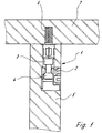
- the fastening device 1 shown in FIG. 1 can also be used as a connecting fitting be referred to, which is equipped with a clamping element 2, which is a rotatable clamping eccentric in the illustrated embodiment.
- This Clamping element 2 interacts with a clamping pin 3, which has a head 4 is equipped, which engages in the clamping element 2.
- the clamping element 2 is in a recess of a first furniture part 5 used.
- the tensioning pin lies with the end 6 opposite the head 6 in a bore of the second furniture part 7, which is a furniture wall in the illustrated embodiment.
- the end 6 of the clamping bolt 3 is surrounded by an expansion element 8 made of plastic.
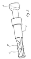
- the clamping bolt 3 is provided with inclined surfaces 9, 10, which lie one behind the other in the longitudinal direction and which are arranged in pairs, so that two oblique surfaces forming a wedge lie opposite each other.
- This Sloping surfaces 9, 10 act with corresponding counter surfaces of the expansion element 8 together.
- the expansion element 8 is produced by means of an injection molding tool, in which of the clamping bolts 3 is inserted. This will cause the sloping surfaces 9, 10 resulting wells filled with plastic.
- the injection mold is designed so that the expansion element 8 is provided with projections 11 on the outside is designed in the manner of threads.
- the outer diameter of the clamping bolt corresponds approximately to the core diameter the projections 11 or the threads.
- Figure 3 shows that the expansion element 8 consists of two parts, the are held together by the projections 11. The individual tabs are therefore seen as bridges. If the clamping bolt 3 with respect to the expansion element 8 move, the projections 11 burst on the opposite Pages, d. H. in the central axis of those formed by the inclined surfaces 9, 10 Wedges. The tensioned, expanded position of the expansion element 8 is shown in FIG. 4.
- Figure 2 shows particularly clearly that the inclined surfaces 9, 10 are flat surfaces are. Since the corresponding counter surfaces result when spraying, the Clamping process achieved that the inclined surfaces 9, 10 and the entire surface against one another.
Description
Die Erfindung betrifft eine Befestigungsvorrichtung für zwei miteinander zu verbindende Möbelteile, die im wesentlichen aus einem mittels eines in ein erstes Möbelteil eingesetzten Spannelementes in seiner Längsrichtung verfahrbaren Spannbolzen und einem in das zweite Möbelteil eingreifenden Spreizeelement besteht, welches den Spannbolzen umhüllt, wobei der Spannbolzen Spannflächen und das Spreizelement entsprechende Gegenflächen aufweist.The invention relates to a fastening device for two to be connected Furniture parts, which essentially consist of a by means of a first furniture part used clamping element in its longitudinal direction movable clamping bolt and a spreading element engaging in the second furniture part, which encased the clamping bolt, the clamping bolt clamping surfaces and the expansion element has corresponding counter surfaces.
Bei der in Frage kommenden Befestigungsvorrichtung (siehe z.B. DE-A-3331496) kann das Spannelement beispielsweise ein Spannexzenter oder eine Schraube sein. Das Spreizelement liegt im gegenüberliegenden Endbreich und kann beispielsweise ein Spreizdübel sein. Die Herstellung der Befestigungsvorrichtung erfolgt, indem der üblicherweise aus Metall bestehende Spannbolzen in ein Spritzgußwerkzeug eingelegt wird, woraufhin das Spreizelement um den Bolzen herumgespritzt wird. Das Umspritzen der Spannbolzen innerhalb des Werkzeuges ist sehr rationell, wodurch Montagekosten eingespart werden.In the case of the fastening device in question (see e.g. DE-A-3331496) the clamping element can, for example be a clamping eccentric or a screw. The expansion element is in the opposite end area and can be, for example, an expansion anchor. The Manufacture of the fastening device is carried out by the usually made of metal existing clamping bolt is inserted into an injection mold, whereupon the Spreading element is sprayed around the bolt. Injection molding of the clamping bolts inside the tool is very efficient, which saves assembly costs become.
Im heutigen modernen Möbelbau ist es gelegentlich erforderlich, daß die Durchmesser des Spannbolzens und des Spreizelementes relativ klein sind, da in den Möbelwänden Reihen von vorgefertigten Bohrungen vorgesehen sind, die aus optischen Gründen klein sind, beispielsweise einen Durchmesser von 5 mm haben.In today's modern furniture, it is sometimes necessary that the diameter of the clamping bolt and the expansion element are relatively small because in the Furniture walls have rows of prefabricated holes that are made of optical Reasons are small, for example have a diameter of 5 mm.
Bei einer bekannten Befestigungsvorrichtung ist der Spannbolzen mit mehreren axial hintereinander angeordneten Konen ausgestattet, die zur Spreizung des Spreizelementes benutzt werden, wenn der Spannbolzen gegenüber dem Spreizelement eine Relativbewegung ausführt. Im Grenzbereich zwischen den beiden Konen ist der Durchmesser des Spannbolzens äußerst gering und wird durch die kleinere Kreisfläche des Querschnittes des Konus definiert.In a known fastening device, the clamping bolt is axial with several Cones arranged one behind the other, which are used to spread the expansion element be used when the clamping bolt against the expansion element Executes relative movement. In the border area between the two cones is the The diameter of the clamping bolt is extremely small and is due to the smaller circular area of the cross section of the cone.
Um den Querschnitt aus Festigkeitsgründen zu vergrößern, ist der Spannbolzen in Bereich der gefährdeten Konen durch axial verlaufende Rippen verstärkt. Der Spannbolzen ist üblicherweise mit vier um einen Winkel von jeweils 90° versetzten Rippen versehen und demzufolge kreuzförmig ausgebildet.To increase the cross section for reasons of strength, the clamping bolt is in Area of the endangered cones reinforced by axially extending ribs. The The clamping bolt is usually offset by four by an angle of 90 ° each Provide ribs and therefore cross-shaped.
Die äußeren Flächen der Rippen liegen fluchtend zur Außenfläche des Spannbolzens. Dieses Maß entspricht in etwa dem Kerndurchmesser des mit einem Außengewinde versehenen Spreizelementes. Anstelle des Außengewindes könnten auch ähnliche Windungen verwendet werden. Diese Gestaltung hat den Grund, daß die in den Innenecken zwischen den Rippen des Spannbolzens ausgebildeten Kunststoffwandungen des Spreizelementes durch die in den Gewinderillen des Spritzgießwerkzeuges ausgebildeten Kunststoffbrücken im unverspannten Ausgangszustand zusammengehalten werden.The outer surfaces of the ribs are flush with the outer surface of the Clamping bolt. This dimension corresponds approximately to the core diameter of the one External thread provided expansion element. Instead of the external thread similar turns can also be used. The reason for this design is that those formed in the inner corners between the ribs of the clamping bolt Plastic walls of the expansion element through the in the thread grooves Injection molding tool trained plastic bridges in the unstressed Initial state are held together.
Beim Zusammenbau eines Möbels sitzt das Spreizelement im unverspannten Zustand mit relativ geringer Reibung in der Bohrung des Möbelteiles. Es muß sichergestellt sein, daß beim Bewegen des Spannbolzens mittels des Spannelementes das Spreizelement in seiner Lage verbleibt und sich nicht bewegt. Dazu ist das Spreizelement mit einem umlaufenden Anschlag ausgestattet, der jedoch äußerst dünn sein muß, da sich sonst ein zu großer Spalt zwischen den beiden zu verbindenden Möbelteilen ergibt. Es ist bislang nicht auszuschließen, daß der Anschlag deformiert wird, wenn sich das Spreizelement axial verschiebt. Diese Verschiebung kann sich ergeben, wenn zum Abreißen der vierreihig ausgebildeten Kunststoffbrücken eine zu große Kraft erforderlich wird. Das Spreizelement kann sich dann auch verschieben, so daß keine ausreichende Relativbewegung zwischen dem Spannbolzen und dem Spreizelement zum Ausspreizen desselben zur Verfügung steht.When assembling a piece of furniture, the expansion element sits in the untensioned state with relatively little friction in the hole in the furniture part. It must be ensured be that when moving the clamping bolt by means of the clamping element Spreading element remains in its position and does not move. This is the expansion element equipped with a circumferential stop, which, however, should be extremely thin must, otherwise there is too large a gap between the two furniture parts to be connected results. So far it cannot be ruled out that the stop will deform when the expansion element moves axially. This shift can change result if one to tear off the four-row plastic bridges great force is required. The expansion element can then also move, so that there is no sufficient relative movement between the clamping bolt and the Spreading element for spreading the same is available.
Weiterhin besteht der Nachteil, daß der um die Konen zur Verfügung stehende Raum, der im Spritzgießwerkzeug mit Kunststoff ausgefüllt wird, geviertelt wird, d. h., daß die Segmente kleinvolumig ausgebildet sind, woraus sich spritztechnische Nachteile ergeben können.Another disadvantage is that the available around the cones Space that is filled with plastic in the injection mold is quartered, d. H., that the segments are small-volume, resulting in injection molding Disadvantages can result.
Darüber hinaus ist noch nachteilig, daß sich bei einer Axialverschiebung die miteinander korrespondierenden Teile, nämlich der Innenkonus des Spreizteiles und der Außenkonus des Spannbolzens verändern, so daß von dem Spannelement zusätzlich noch Verformungsarbeit am Spreizteil aufgebracht werden muß, wodurch sich der Wirkungsgrad verschlechtert, da diese Arbeit bzw. die Kraft für den eigentlichen Spannvorgang nicht mehr zur Verfügung steht. Dies gilt insbesondere für relativ klein ausgebildete Spannelemente, die nur eine begrenzte Zugkraft entwickeln können.In addition, it is also disadvantageous that with an axial displacement corresponding parts, namely the inner cone of the expansion part and the Change the outer cone of the clamping bolt, so that additional of the clamping element deformation work must still be applied to the expansion part, whereby the efficiency deteriorates because this work or the strength for the actual Clamping process is no longer available. This is especially true for relatively small trained clamping elements that can only develop a limited tractive force.
Der Erfindung liegt die Aufgabe zugrunde, eine Befestigungsvorrichtung der eingangs näher beschriebenen Art so zu gestalten, daß sich das Spreizelement beim Anziehen des Spannbolzens nicht verschiebt, daß die notwendige Kraft zur Zerstörung der Brückenstege des Spreizelementes herabgesetzt wird und daß die aufgebrachte Kraft im wesentlichen vollständig in den Spannvorgang umgesetzt wird und daß darüber hinaus eine spritztechnisch günstige Form für das Spannelement erreicht wird.The invention has for its object a fastening device of the beginning to be described in more detail so that the expansion element when tightening of the clamping bolt does not move that the necessary force to destroy the Bridge webs of the expansion element is lowered and that the applied Force is essentially completely implemented in the clamping process and that also achieved a favorable injection molding shape for the clamping element becomes.
Die gestellte Aufgabe wird gelöst, indem der Spannbolzen wenigstens eine einen Keil bildende, ebene Schrägfäche aufweist und daß das Spreizelement eine entsprechende an der Schrägfläche anliegende Gegenfläche aufweist.The task is solved by the clamping bolt at least one wedge has forming, flat inclined surface and that the expansion element has a corresponding has mating surface abutting the inclined surface.
Der in das Spritzgießwerkzeug eingelegte Spannbolzen wird im Bereich des Keiles oder der Keile mit dem Spreizelement umspritzt. Dadurch liegen die Innenflächen des Spreizelementes vollflächig an den Außenflächen des Spannelementes an. Wird beim Spannvorgang der Spannbolzen durch das Spannelement angezogen, wirken ebene Keilflächen aufeinander, so daß nunmehr keine Verformungsarbeit geleistet werden muß. Die Keilflächen bilden stets eine ebene, flächige Anlage zueinander.The clamping bolt inserted in the injection mold is in the area of the wedge or overmolded the wedges with the expansion element. As a result, the inner surfaces of the Spreading element over the entire surface on the outer surfaces of the clamping element. Becomes tightened by the clamping element during the clamping process flat wedge surfaces on top of each other, so that no deformation work is done must become. The wedge surfaces always form a flat, flat contact with each other.
In einer bevorzugten Ausführungsform ist vorgesehen, daß der Spannbolzen zwei einander gegenüberliegende, den Keil bildende Schrägflächen aufweist, und daß das Spreizelement mit zwei einander gegenüberliegenden Brückenstegen ausgestattet ist, die beim Spannvorgang bersten. Die Brückenstege werden durch die Gewindeflanken gebildet. Da sie nur an zwei einander gegenüberliegenden Seiten vorgesehen sind, wird die zum Bersten notwendige Reißkraft gegenüber der bisherigen Ausführung halbiert. Da der Durchmesser des Spannbolzens im Normalfall relativ klein ist, ist die Länge jeder Keilfläche begrenzt. Damit jedoch eine asureichende Länge für das Spreizelement erreicht wird, ist in weiterer Ausgestaltung vorgesehen, daß der Spannbolzen mehrere in Längsrichtung hintereinander angeordnete ebene Schrägflächen aufweist, die paarweise und einander gegenüberliegend angeordnet sind. In der Projektion gesehen sind die Schrägflächen dreieckförmig ausgestaltet.In a preferred embodiment it is provided that the clamping bolt two has opposing inclined surfaces forming the wedge, and that Expansion element equipped with two bridge bridges opposite each other that burst during the tensioning process. The bridge webs are through the thread flanks educated. Since they are only provided on two opposite sides are the tearing force necessary for bursting compared to the previous one Halved version. Because the diameter of the clamping bolt is usually relative is small, the length of each wedge surface is limited. However, this is a sufficient Length is reached for the expansion element is provided in a further embodiment, that the clamping bolt several levels arranged one behind the other in the longitudinal direction Inclined surfaces arranged in pairs and opposite each other are. Seen in the projection, the inclined surfaces are triangular.
Anhand der beiliegenden Zeichnungen wird die Erfindung noch näher erläutert.The invention is explained in more detail with reference to the accompanying drawings.
Es zeigen:
- Figur 1
- eine zwei rechtwinklig zueinander stehende Möbelteile verbindende Befestigungsvorrichtung,
Figur 2- den Spannbolzen der Befestigungsvorrichtung nach der Figur 1 als Einzelheit,
Figur 3- den in das Spreizelement eingesetzten Spannbolzen im unverspannten Zustand in einer Schnittdarstellung,
Figur 4- eine um 90° gegenüber der
Figur 3 versetzte Schnittdarstellung, die Aufweitung des Spreizelementes zeigend.
- Figure 1
- a fastening device connecting two pieces of furniture standing at right angles to one another,
- Figure 2
- the clamping bolt of the fastening device according to Figure 1 as a detail,
- Figure 3
- the clamping bolt inserted into the expansion element in the unstressed state in a sectional view,
- Figure 4
- a sectional view offset by 90 ° with respect to FIG. 3, showing the expansion of the expansion element.
Die in der Figur 1 dargestellte Befestigungsvorrichtung 1 kann auch als Verbindungsbeschlag
bezeichnet werden, der mit einem Spannelement 2 ausgerüstet ist, welches
im dargestellten Ausführungsbeispiel ein drehbarer Spannexzenter ist. Dieses
Spannelement 2 wirkt mit einem Spannbolzen 3 zusammen, der mit einem Kopf 4
ausgerüstet ist, welcher in das Spannelement 2 eingreift. Das Spannelement 2 ist in
einer Ausnehmung eines ersten Möbelteiles 5 eingesetzt. Der Spannbolzen liegt mit
dem dem Kopf 4 gegenüberliegenden Ende 6 in einer Bohrung des zweiten Möbelteiles
7, welches im dargestellten Ausführungsbeispiel eine Möbelwand ist. Das Ende
6 des Spannbolzens 3 ist von einem aus Kunststoff gefertigten Spreizelement 8 umgeben.The fastening device 1 shown in FIG. 1 can also be used as a connecting fitting
be referred to, which is equipped with a
Wie die Figur 2 deutlich zeigt, ist der Spannbolzen 3 mit Schrägflächen 9, 10 versehen,
die in Längsrichtung hintereinander liegen und die paarweise angeordnet sind,
so daß sich jeweils zwei einen Keil bildende Schrägflächen gegenüberliegen. Diese
Schrägflächen 9, 10 wirken mit entsprechenden Gegenflächen des Spreizelementes
8 zusammen. As FIG. 2 clearly shows, the
Die Herstellung des Spreizelementes 8 erfolgt mittels eines Spritzgießwerkzeuges, in
welches der Spannbolzen 3 eingelegt wird. Dadurch werden die durch die Schrägflächen
9, 10 entstehenden Vertiefungen mit Kunststoff ausgefüllt. Das Spritzgießwerkzeug
ist so gestaltet, daß das Spreizelement 8 außen mit Vorsprüngen 11 versehen
ist, die nach Art von Gewindegängen gestaltet sind.The expansion element 8 is produced by means of an injection molding tool, in
which of the
Der Außendurchmesser des Spannbolzens entspricht in etwa dem Kerndurchmesser
der Vorsprünge 11 bzw. der Gewindegänge.The outer diameter of the clamping bolt corresponds approximately to the core diameter
the
Insbesondere die Figur 3 zeigt, daß das Spreizelement 8 aus zwei Teilen besteht, die
durch die Vorsprünge 11 zusammengehalten werden. Die einzelnen Vorsprünge sind
daher wie Brückenstege zu sehen. Wird der Spannbolzen 3 gegenüber dem Spreizelement
8 verfahren, bersten die Vorsprünge 11 an den einander gegenüberliegenden
Seiten, d. h. in der Mittelachse der durch die Schrägflächen 9, 10 gebildeten
Keile. Die verspannte, aufgeweitete Stellung des Spreizelementes 8 zeigt die Figur 4.In particular, Figure 3 shows that the expansion element 8 consists of two parts, the
are held together by the
Die Figur 2 zeigt besonders deutlich, daß die Schrägflächen 9, 10 ebene Flächen
sind. Da sich beim Spritzen die entsprechenden Gegenflächen ergeben, wird beim
Spannvorgang erreicht, daß die Schrägflächen 9, 10 und die Gegenflächen vollflächig
aneinanderliegen.Figure 2 shows particularly clearly that the
Claims (4)
- Fastening device for two furniture parts which are to be connected to one another, the device essentially comprising a clamping bolt, which can be displaced in its longitudinal direction by means of a clamping element inserted into a first furniture part, and an expanding element, which engages in the second furniture part and encloses the clamping bolt, the clamping bolt having clamping surfaces and the expanding element having corresponding mating surfaces, characterized in that the clamping bolt (3) has at least one wedge-forming, planar sloping surface (9, 10), and in that the expanding element (8) has a corresponding mating surface butting against the sloping surfaces (9, 10).
- Fastening device according to Claim 1, characterized in that the clamping bolt (3) has two mutually opposite, wedge-forming sloping surfaces (9, 10), and in that the expanding element (8) is provided with two mutually opposite bridge crosspieces which rupture during the clamping operation.
- Fastening device according to Claim 2, characterized in that the clamping bolt (3) has a plurality of planar sloping surfaces (9, 10) which are arranged one behind the other in the longitudinal direction and are located opposite one another in pairs.
- Fastening device according to Claim 3, characterized in that the bridge crosspieces are formed by protrusions (11) preferably in the form of thread turns.
Applications Claiming Priority (4)
| Application Number | Priority Date | Filing Date | Title |
|---|---|---|---|
| DE29802610U | 1998-02-17 | ||
| DE29802610U DE29802610U1 (en) | 1998-02-17 | 1998-02-17 | Fastening device |
| DE29808235U DE29808235U1 (en) | 1998-02-17 | 1998-05-07 | Fastening device |
| DE29808235U | 1998-05-07 |
Publications (3)
| Publication Number | Publication Date |
|---|---|
| EP0940587A2 EP0940587A2 (en) | 1999-09-08 |
| EP0940587A3 EP0940587A3 (en) | 2001-01-10 |
| EP0940587B1 true EP0940587B1 (en) | 2002-12-11 |
Family
ID=26061220
Family Applications (1)
| Application Number | Title | Priority Date | Filing Date |
|---|---|---|---|
| EP19990102434 Expired - Lifetime EP0940587B1 (en) | 1998-02-17 | 1999-02-09 | Fastening device |
Country Status (3)
| Country | Link |
|---|---|
| EP (1) | EP0940587B1 (en) |
| DK (1) | DK0940587T3 (en) |
| ES (1) | ES2186260T3 (en) |
Families Citing this family (4)
| Publication number | Priority date | Publication date | Assignee | Title |
|---|---|---|---|---|
| DE20118279U1 (en) | 2001-11-09 | 2002-01-31 | Haefele Gmbh & Co | Link between two components |
| AT508385B1 (en) | 2009-10-12 | 2011-01-15 | Blum Gmbh Julius | FASTENING DEVICE FOR FURNITURE FITTINGS |
| EP3907413A1 (en) | 2012-09-12 | 2021-11-10 | Flooring Industries Limited, SARL | Connection device for two furniture parts which have to be interconnected, as well as furniture applying such connection device |
| DE202015105030U1 (en) * | 2015-09-23 | 2015-10-19 | Häfele GmbH & Co KG | Spreader sleeve overmolded connecting spreader pin |
Family Cites Families (1)
| Publication number | Priority date | Publication date | Assignee | Title |
|---|---|---|---|---|
| DE3331496A1 (en) * | 1983-09-01 | 1985-04-04 | Peter Dipl.-Ing. 8500 Nürnberg Wölfel | Device for holding structural elements |
-
1999
- 1999-02-09 DK DK99102434T patent/DK0940587T3/en active
- 1999-02-09 ES ES99102434T patent/ES2186260T3/en not_active Expired - Lifetime
- 1999-02-09 EP EP19990102434 patent/EP0940587B1/en not_active Expired - Lifetime
Also Published As
| Publication number | Publication date |
|---|---|
| ES2186260T3 (en) | 2003-05-01 |
| EP0940587A2 (en) | 1999-09-08 |
| DK0940587T3 (en) | 2003-04-07 |
| EP0940587A3 (en) | 2001-01-10 |
Similar Documents
| Publication | Publication Date | Title |
|---|---|---|
| DE3742493C2 (en) | Fastener and method for its attachment | |
| EP1259738B1 (en) | Profile connecting device | |
| DE2328385A1 (en) | EXPANSION DOWEL | |
| DE1475216A1 (en) | Screw-nut connection that can be tightened on one side | |
| EP0758039A1 (en) | Anchorage rail for use in construction work | |
| CH656193A5 (en) | SPREADING DOWEL. | |
| DD284952A5 (en) | DEVICE FOR ATTACHING INDIVIDUAL OBJECTS TO A HOLDING ELEMENT | |
| EP0594872B1 (en) | Assembly for the erection of wall and/or ceiling constructions, in particular in exhibition construction | |
| DE3128610C2 (en) | ||
| DE4006028A1 (en) | Connecting bolt for machine elements | |
| EP0940587B1 (en) | Fastening device | |
| DE3429585A1 (en) | FASTENING KIT CONSISTING OF A PLASTIC SPREADING ANCHOR AND A FASTENING SCREW | |
| DE19825884A1 (en) | Undercut dowels | |
| DE69828298T2 (en) | DEVICES FOR MANUFACTURING A CONNECTION | |
| EP0381678B1 (en) | Undercutting drilling pin | |
| EP0388694B1 (en) | Expandible plug | |
| DE4236323A1 (en) | Locking connection of rigid, pressure medium supply to housing - has pipe retainer in housing borehole comprising locating and locking sleeve | |
| EP0964169B1 (en) | Frame dowel | |
| EP1749953A2 (en) | Spindle with clamping | |
| EP0834659B1 (en) | Expansion dowel | |
| DE7046337U (en) | TUNNEL LINING SEGMENT | |
| DE3437846C2 (en) | ||
| DE4024963A1 (en) | DOWEL WITH A DOWEL SLEEVE | |
| DE4006671C1 (en) | ||
| DE2619728C3 (en) | Blind fasteners, in particular for use in the planking of an aircraft or the like |
Legal Events
| Date | Code | Title | Description |
|---|---|---|---|
| PUAI | Public reference made under article 153(3) epc to a published international application that has entered the european phase |
Free format text: ORIGINAL CODE: 0009012 |
|
| AK | Designated contracting states |
Kind code of ref document: A2 Designated state(s): BE DE DK ES FR GB NL SE |
|
| AX | Request for extension of the european patent |
Free format text: AL;LT;LV;MK;RO;SI |
|
| PUAL | Search report despatched |
Free format text: ORIGINAL CODE: 0009013 |
|
| AK | Designated contracting states |
Kind code of ref document: A3 Designated state(s): AT BE CH CY DE DK ES FI FR GB GR IE IT LI LU MC NL PT SE |
|
| AX | Request for extension of the european patent |
Free format text: AL;LT;LV;MK;RO;SI |
|
| 17P | Request for examination filed |
Effective date: 20010704 |
|
| AKX | Designation fees paid |
Free format text: BE DE DK ES FR GB NL SE |
|
| GRAH | Despatch of communication of intention to grant a patent |
Free format text: ORIGINAL CODE: EPIDOS IGRA |
|
| GRAH | Despatch of communication of intention to grant a patent |
Free format text: ORIGINAL CODE: EPIDOS IGRA |
|
| GRAA | (expected) grant |
Free format text: ORIGINAL CODE: 0009210 |
|
| AK | Designated contracting states |
Kind code of ref document: B1 Designated state(s): BE DE DK ES FR GB NL SE |
|
| REG | Reference to a national code |
Ref country code: GB Ref legal event code: FG4D Free format text: NOT ENGLISH |
|
| REF | Corresponds to: |
Ref document number: 59903704 Country of ref document: DE Date of ref document: 20030123 |
|
| REG | Reference to a national code |
Ref country code: SE Ref legal event code: TRGR |
|
| REG | Reference to a national code |
Ref country code: DK Ref legal event code: T3 |
|
| GBT | Gb: translation of ep patent filed (gb section 77(6)(a)/1977) |
Effective date: 20030325 |
|
| REG | Reference to a national code |
Ref country code: ES Ref legal event code: FG2A Ref document number: 2186260 Country of ref document: ES Kind code of ref document: T3 |
|
| ET | Fr: translation filed | ||
| PLBE | No opposition filed within time limit |
Free format text: ORIGINAL CODE: 0009261 |
|
| STAA | Information on the status of an ep patent application or granted ep patent |
Free format text: STATUS: NO OPPOSITION FILED WITHIN TIME LIMIT |
|
| 26N | No opposition filed |
Effective date: 20030912 |
|
| PGFP | Annual fee paid to national office [announced via postgrant information from national office to epo] |
Ref country code: NL Payment date: 20040216 Year of fee payment: 6 |
|
| PGFP | Annual fee paid to national office [announced via postgrant information from national office to epo] |
Ref country code: ES Payment date: 20040223 Year of fee payment: 6 |
|
| PGFP | Annual fee paid to national office [announced via postgrant information from national office to epo] |
Ref country code: SE Payment date: 20040224 Year of fee payment: 6 |
|
| PGFP | Annual fee paid to national office [announced via postgrant information from national office to epo] |
Ref country code: BE Payment date: 20040308 Year of fee payment: 6 |
|
| PG25 | Lapsed in a contracting state [announced via postgrant information from national office to epo] |
Ref country code: SE Free format text: LAPSE BECAUSE OF NON-PAYMENT OF DUE FEES Effective date: 20050210 Ref country code: ES Free format text: LAPSE BECAUSE OF NON-PAYMENT OF DUE FEES Effective date: 20050210 |
|
| PG25 | Lapsed in a contracting state [announced via postgrant information from national office to epo] |
Ref country code: BE Free format text: LAPSE BECAUSE OF NON-PAYMENT OF DUE FEES Effective date: 20050228 |
|
| BERE | Be: lapsed |
Owner name: *HETTICH-HEINZE G.M.B.H. & CO. K.G. Effective date: 20050228 |
|
| PG25 | Lapsed in a contracting state [announced via postgrant information from national office to epo] |
Ref country code: NL Free format text: LAPSE BECAUSE OF NON-PAYMENT OF DUE FEES Effective date: 20050901 |
|
| EUG | Se: european patent has lapsed | ||
| NLV4 | Nl: lapsed or anulled due to non-payment of the annual fee |
Effective date: 20050901 |
|
| REG | Reference to a national code |
Ref country code: ES Ref legal event code: FD2A Effective date: 20050210 |
|
| PGFP | Annual fee paid to national office [announced via postgrant information from national office to epo] |
Ref country code: GB Payment date: 20070223 Year of fee payment: 9 |
|
| PGFP | Annual fee paid to national office [announced via postgrant information from national office to epo] |
Ref country code: DK Payment date: 20070228 Year of fee payment: 9 |
|
| PGFP | Annual fee paid to national office [announced via postgrant information from national office to epo] |
Ref country code: DE Payment date: 20070326 Year of fee payment: 9 |
|
| BERE | Be: lapsed |
Owner name: *HETTICH-HEINZE G.M.B.H. & CO. K.G. Effective date: 20050228 |
|
| PGFP | Annual fee paid to national office [announced via postgrant information from national office to epo] |
Ref country code: FR Payment date: 20070216 Year of fee payment: 9 |
|
| REG | Reference to a national code |
Ref country code: DK Ref legal event code: EBP |
|
| GBPC | Gb: european patent ceased through non-payment of renewal fee |
Effective date: 20080209 |
|
| REG | Reference to a national code |
Ref country code: FR Ref legal event code: ST Effective date: 20081031 |
|
| PG25 | Lapsed in a contracting state [announced via postgrant information from national office to epo] |
Ref country code: DK Free format text: LAPSE BECAUSE OF NON-PAYMENT OF DUE FEES Effective date: 20080229 Ref country code: DE Free format text: LAPSE BECAUSE OF NON-PAYMENT OF DUE FEES Effective date: 20080902 |
|
| PG25 | Lapsed in a contracting state [announced via postgrant information from national office to epo] |
Ref country code: FR Free format text: LAPSE BECAUSE OF NON-PAYMENT OF DUE FEES Effective date: 20080229 |
|
| PG25 | Lapsed in a contracting state [announced via postgrant information from national office to epo] |
Ref country code: GB Free format text: LAPSE BECAUSE OF NON-PAYMENT OF DUE FEES Effective date: 20080209 |