EP0834659B1 - Expansion dowel - Google Patents
Expansion dowel Download PDFInfo
- Publication number
- EP0834659B1 EP0834659B1 EP97114718A EP97114718A EP0834659B1 EP 0834659 B1 EP0834659 B1 EP 0834659B1 EP 97114718 A EP97114718 A EP 97114718A EP 97114718 A EP97114718 A EP 97114718A EP 0834659 B1 EP0834659 B1 EP 0834659B1
- Authority
- EP
- European Patent Office
- Prior art keywords
- expansible
- tongues
- expansion
- section
- cross
- Prior art date
- Legal status (The legal status is an assumption and is not a legal conclusion. Google has not performed a legal analysis and makes no representation as to the accuracy of the status listed.)
- Expired - Lifetime
Links
- 210000002105 tongue Anatomy 0.000 claims description 114
- 210000002414 leg Anatomy 0.000 description 13
- 238000003780 insertion Methods 0.000 description 10
- 230000037431 insertion Effects 0.000 description 10
- 238000004873 anchoring Methods 0.000 description 7
- 230000002093 peripheral effect Effects 0.000 description 6
- 238000002347 injection Methods 0.000 description 5
- 239000007924 injection Substances 0.000 description 5
- 238000001746 injection moulding Methods 0.000 description 4
- 239000004033 plastic Substances 0.000 description 2
- 239000004952 Polyamide Substances 0.000 description 1
- 230000006378 damage Effects 0.000 description 1
- 230000000694 effects Effects 0.000 description 1
- 230000002349 favourable effect Effects 0.000 description 1
- 229920002647 polyamide Polymers 0.000 description 1
- 125000006850 spacer group Chemical group 0.000 description 1
- 239000007921 spray Substances 0.000 description 1
- 210000000689 upper leg Anatomy 0.000 description 1
Images

Classifications
-
- F—MECHANICAL ENGINEERING; LIGHTING; HEATING; WEAPONS; BLASTING
- F16—ENGINEERING ELEMENTS AND UNITS; GENERAL MEASURES FOR PRODUCING AND MAINTAINING EFFECTIVE FUNCTIONING OF MACHINES OR INSTALLATIONS; THERMAL INSULATION IN GENERAL
- F16B—DEVICES FOR FASTENING OR SECURING CONSTRUCTIONAL ELEMENTS OR MACHINE PARTS TOGETHER, e.g. NAILS, BOLTS, CIRCLIPS, CLAMPS, CLIPS OR WEDGES; JOINTS OR JOINTING
- F16B13/00—Dowels or other devices fastened in walls or the like by inserting them in holes made therein for that purpose
- F16B13/12—Separate metal or non-separate or non-metal dowel sleeves fastened by inserting the screw, nail or the like
- F16B13/128—Separate metal or non-separate or non-metal dowel sleeves fastened by inserting the screw, nail or the like with extending protrusions, e.g. discs, segments, ridges, fingers or tongues
Definitions
- the invention relates to an expansion anchor according to the preamble of claim 1.
- expansion anchors are usually made of plastic by injection molding. They have a tubular insertion section for a screw, from which itself Extend spreading tongues to a front end of the expansion anchor.
- the expansion anchor is inserted into a drill hole in a masonry and by screwing in the screw between its spreading tongues, these are spread apart radially, so that the Spread tongues are pressed against a borehole wall and the expansion anchor with the Screw is anchored in the masonry.
- an expansion anchor in which in an expansion area through a longitudinal slot in an axial plane of the expansion anchor two in cross section semicircular spreading tongues are formed.
- the two spread tongues are parallel to the Slot plane curved in opposite directions.
- the Facing the longitudinal slot the expansion tongues have semicircular grooves in cross section that face each other when the expansion anchor is not deformed.
- the known expansion anchor has the disadvantage that its expansion tongues only over a short peripheral section adjoining the longitudinal slot separating them abut a borehole wall, which is the contact surface of the known expansion anchor limited to a small part of its size.
- the invention has for its object a expansion plug of the aforementioned Kind in such a way that its anchoring force in the borehole is increased.
- the Expansion dowel according to the invention has a larger one in the area of its expansion tongues Transverse dimension as the borehole in which it is to be anchored.
- the expansion tongues are pressed radially towards each other, so that spaces between the tongues narrow or close. This results in a large area of the expansion anchor on the whole or at least almost the entire circumferential surface of the borehole wall.
- This compared to known ones Expansion dowels enlarged contact surface improves the hold of the invention Expansion dowel in the borehole and increases its anchoring force.
- the spaces between the expansion tongues are preferably dimensioned so large that that they are at least on the circumference of the expansion anchor completely or almost close completely when the expansion anchor is inserted into the borehole. Thereby becomes an essentially closed one in the expansion area of the expansion anchor Circumferential surface without interruptions between the expansion tongues and thus the Largest possible contact surface on the borehole wall for a given borehole diameter reached.
- the expansion anchor according to the invention has two at a distance from each other and mutually opposite spread tongues with essentially circular segment-shaped cross section. There are two between these two tongues further spreading tongues arranged in the middle of the expansion dowel some distance have from each other and extend radially to the outer circumference.
- the expansion anchor points in the area of its expansion tongues a cylindrical, at the gaps between Spreading tongues interrupted, cylindrical outer surface, the diameter of which is larger than a diameter of the borehole in which the expansion plug is to be inserted. This Forming the expansion anchor enables the expansion tongues when inserted into the Compress the borehole in the radial direction so that the interruptions close the outer surface.
- the expansion anchor according to the invention preferably has three, in particular four or more spreads on. This avoids that the expansion anchor Preferred direction like an expansion plug with only two expansion tongues, the perpendicular to a dividing plane between its two tongues, i.e. in the direction in which its splayings are spread apart to absorb higher transverse forces is able to than in the parting plane.
- Another advantage of the larger number of spread tongues is the better distribution of the spreading forces over the entire circumference of the borehole, in which the expansion anchor is anchored. This increases the anchoring power of the Expansion dowels in the borehole.
- the scope serves to form the expansion anchor according to the invention with expansion tongues, whose cross-sectional areas have approximately the same area.
- Such cross-sectional areas of the same size have an approximate effect equally strong deformation of the expansion tongues when spreading the expansion anchor squeezed between the spreading screw and the borehole wall become.
- the approximately equal deformation leads to approximately the same large pressure forces of the expansion tongues against the borehole wall.
- the invention provided that at least one of the expansion tongues, preferably two opposite each other approximately tangentially or approximately Has wing elements projecting circumferentially. Such wing elements increase the elasticity of the expansion tongue and cause an enlargement of the Contact surface.
- expansion tongues are approximately circular segment-shaped Cross sections provided. This has the advantage that all spreads with have the same cross-section formed. This creates equal spreading forces for all Spread tongues achieved.
- the expansion tongues are together at their two ends connected. This improves torsional rigidity of the expansion anchor and prevents that the expansion dowel turns around its longitudinal axis when the screw is screwed in twisted. Furthermore, it is avoided that one or more spreading tongues from the Screw aside in the tangential direction in the borehole so that The screw and spreading tongue come to lie next to each other.
- the expansion tongues with longitudinal guide grooves on their mutually facing inner sides form, the edge of which guide the screw.
- the spaces between the expansion tongues preferably form in one another slots located in parallel planes.
- These slots can be used in injection molding by forming ribs parallel to each other in a mold cavity, see above that the finished spray dowel can be easily removed from an injection tool can.
- the expansion dowel according to the invention can thereby be used with a simple injection tool produce the two matching, mirror-image arranged tool halves with essentially semi-cylindrical recesses into which the ribs for Form the slots between the expansion tabs of the expansion anchor, and has a core.
- the slots can widen to the circumference of the expansion anchor.
- the expansion tabs of the expansion anchor according to the invention can be used over their entire length Length separated from each other and connected to each other only at one or both ends his.
- the spread tongues can be used spread minimal force, whereby the screwing torque of the screw is small.
- the spread tongues are mutually adjacent spread tongues individual points of their length or continuously connected elastically.
- the longitudinal guide of the screw to be screwed improved is the longitudinal guide of the screw to be screwed improved.
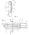
- Expansion dowel 10 is in one piece as an injection molded part made of plastic, in particular of Made of polyamide. It has a tubular insertion sleeve 12 at a rear end on, from which there are four spreading tongues 14, 16 over a spreading area 18 extend front end 20 of the expansion anchor.
- Two spacing tongues 14 which are opposite one another at a distance have segments of a circle Cross section on.
- the two other spreading tongues 16 are also mutually exclusive opposite in a space between the circular segment-shaped cross section having spacer tongues 14 arranged.
- These expansion tongues 16 have a U-shape Cross section and have some distance from each other.
- Yoke walls 22 of the in Cross-section U-shaped expansion legs 16 are located on the circumference of the expansion anchor 10, while their leg walls 24 protrude into the interior of the expansion anchor 10.
- the Yoke walls 22 of the expansion tongues 16 are rounded.
- the four spreading legs 14, 16 are mutually movable and can be Push outwards and inwards in the radial direction.
- the spreading legs 14, 16 delimit one that extends over the expansion area 18 of the expansion anchor 10 Interior 30 with a cross-shaped cross section between them.
- the expansion tongues 14, 16 form a cylindrical one, on the slots 28 interrupted lateral surface, the diameter of which is larger than an outer diameter of the Introducer sleeve 12 is.
- the outer diameter of the insertion sleeve 12 corresponds to a nominal diameter of the expansion anchor 10 and thus a diameter of a borehole, the is provided for inserting the expansion anchor 10.
- the rear ends of the expansion tongues 16 with a U-shaped cross section are inclined locking pawls 32 that run outward (FIG. 1), which engage the expansion dowel 10 give additional hold in the borehole.
- the spreading tongues are at their rear ends 16 U-shaped cross section is not connected to the insertion sleeve 12. They are at the front end 20 of the expansion anchor 10 with the expansion tongues 14 circular segment-shaped cross-section connected in one piece.
- the spread tongues 14 Circular segment-shaped cross-section are integral with the at its rear end Insertion sleeve 12 so that the expansion tongues 16 have a U-shaped cross section Spreader tongues 14 in the form of a segment of a circle in one piece with the insertion sleeve 12 are.
- the expansion anchor 10 when inserting the expansion anchor 10 according to the invention into a borehole 34 in a wall 36 made of concrete, the four expansion tongues 14, 16 become radial pressed inwards and towards each other ( Figure 4).
- the slots 28 close between the expansion tongues 14 circular segment-shaped cross section and the between Spreading tongues 16 lying in them with an inwardly open, U-shaped cross section largely.
- the expansion anchor 10 lies in its expansion area 18 except for small ones Interruptions at the slots 28 all over on a peripheral wall of the borehole 34 at.
- the expansion anchor 10 according to the invention thus has a given borehole diameter the largest possible contact area, which is a great anchorage force in the Masonry 36 results.
- a screw for anchoring, a screw, not shown, is inserted through the insertion sleeve 12 into the Expansion dowel 10 inserted and screwed between the expansion tongues 14, 16.
- the spreading tongues 16 U-shaped cross section a good, with an imaginary longitudinal axis of the expansion anchor 10 aligned longitudinal guide on four over the circumference of one Screw thread of the screw to be screwed in distributed points.
- the screw presses the two expansion legs 16 U-shaped cross section in the radial direction outside against the peripheral wall of the borehole 34.
- the free ends the leg walls 24 spread apart and against the base sides 26 of the expansion tongues 14 circular segment-shaped cross section pressed.
- the Spreader tongues 14 in the shape of a segment of a circle in the radial direction and thus transversely to the expansion tongues 16 U-shaped cross section, apart and against the peripheral wall of the borehole 34 pressed.
- the connected only at the front end 20 and spread tongues 14, 16 separated from one another over their entire length hardly oppose the screwing in, so that a screwing torque the screw with high efficiency in a spreading of the expansion legs 14, 16 is implemented against the peripheral wall of the borehole 34.
- the slots 28 are between the expansion tongues 14 circular segment-shaped cross-section and the expansion tongues U-shaped cross-section proportionally wide in relation to the diameter of the expansion anchor. This is injection molding favorable because the slots 28 are made with ribs of an injection mold leave, which have sufficient stability due to their thickness to the at Injection molding can withstand loads without deforming.
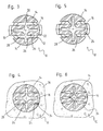
- FIG. 5 shows a cross section according to FIG. 3 of a second embodiment of a Expansion dowels according to the invention 10.
- This embodiment of the invention mutually adjacent spreading tongues 14, 16 elastically connected to one another over their length.
- the leg walls 24 of the expansion tongues 16 have a U-shaped cross section their inner ends in one piece in a central region of the base sides 26 of the expansion tongues 14 circular cross-section.
- the slots 28 between the Spreading tongues 14 circular segment-shaped cross section and the spreading tongues 16 U-shaped Cross-section are not continuous, they end inside the Expansion dowel 10.
- This embodiment of the expansion dowel 10 according to the invention is improved the longitudinal guidance of a screw when screwing in. Otherwise, the in Figure 5 shown expansion anchor 10 with the expansion anchor 10 shown in Figure 3 match.
- the same reference numerals are used for the same parts and it becomes in this respect reference is made to the above explanations relating to FIGS. 1 to 4.
- FIG. 6 shows the cross section from FIG. 5 with the expansion plug inserted in a borehole 34 10.
- the slots 28 between the expansion tongues 14, 16 are on their outer Ends completely closed, so that the expansion tongues 14, 16 on without interruption abut the peripheral wall of the borehole 34.
- Expansion dowel 40 has a tubular insertion sleeve 42 at a rear end and a tubular sleeve 44 at a front end, between which there are four Spread tongues 46, 48 extend. All four expansion tongues 46, 48 go at their ends in one piece in the insertion sleeve 42 and in the sleeve 44 at the front end of the expansion anchor 40 over. The spreading tongues 46, 48 are thus in one piece at their two ends connected with each other.
- the spreading tongues 46, 48 have a large part of their length as shown in FIG Cross sections on: have two mutually opposite expansion tongues 46 an approximately rectangular cross section. Outer surfaces 50 of these expansion tongues 46 have a curvature which corresponds to a curvature of a borehole wall, into which the expansion plug 40 is inserted. Interiors facing each other 52 of the rectangular spreading tongues 46 are beveled triangular in cross section.
- the two other, also opposite spreading tongues 48 have a longitudinally extending, in cross-section triangular web 54, of which Project wing elements 56 on both sides in the tangential direction.
- the wing elements 56 are in one piece with the web 54, they extend essentially over the total length of the expansion tongues 48.
- the wing elements 56 have curved outer surfaces 58.
- the wing elements 56 enlarge the outer surface of the expansion tongues 48 and thus the contact surface of the expansion anchor 40 in the borehole.
- the wing elements 56 fit due to their elasticity when spreading against the borehole wall.
- the expansion tongues 46, 48 change in the direction of the front end of the expansion anchor 40 their cross sections, as shown in Figure 9: all point in the area of the front end four spreading tongues 46, 48 match a cross-section in the form of a segment of a circle.
- the guide grooves 60 extend over the entire length of the expansion tongues 46, 48 to to the sleeve 44 at the front end of the expansion anchor 40.
- the cross sections of the expansion tongues 46, 48 (this also applies to the expansion tongues 14, 16 of the one shown in FIGS. 1 to 6 Expansion dowels 10) can therefore change over their length or one Have a constant cross-section over their entire length.
- the cross-sectional area of the expansion tongues 46, 48 of the one shown in FIG Cross-sections are approximately the same size.
Description
Die Erfindung betrifft einen Spreizdübel gemäß dem Oberbegriff des Anspruchs 1.The invention relates to an expansion anchor according to the preamble of claim 1.
Derartige Spreizdübel sind üblicherweise durch Spritzgießen aus Kunststoff hergestellt. Sie weisen einen rohrförmigen Einführabschnitt für eine Schraube auf, von dem aus sich Spreizzungen zu einem vorderen Ende des Spreizdübels erstrecken. Der Spreizdübel wird in ein Bohrloch in einem Mauerwerk eingesetzt und durch Eindrehen der Schraube zwischen seine Spreizzungen werden diese radial auseinandergespreizt, so daß die Spreizzungen gegen eine Bohrlochwand gedrückt werden und der Spreizdübel mit der Schraube im Mauerwerk verankert ist.Such expansion anchors are usually made of plastic by injection molding. They have a tubular insertion section for a screw, from which itself Extend spreading tongues to a front end of the expansion anchor. The expansion anchor is inserted into a drill hole in a masonry and by screwing in the screw between its spreading tongues, these are spread apart radially, so that the Spread tongues are pressed against a borehole wall and the expansion anchor with the Screw is anchored in the masonry.
Aus der DE-A-33 29 502 ist ein Spreizdübel bekannt, bei dem in einem Spreizbereich durch einen Längsschlitz in einer Axialebene des Spreizdübels zwei im Querschnitt halbkreisförmige Spreizzungen gebildet sind. Die beiden Spreizzungen sind parallel zur Schlitzebene in einander entgegengesetzte Richtungen gebogen ausgebildet. Dem Längsschlitz zugewandt weisen die Spreizzungen im Querschnitt halbkreisförmige Nuten auf, die bei unverformtem Spreizdübel einander gegenüberliegen. Beim Einbringen des Spreizdübels in ein Bohrloch werden die beiden Spreizzungen parallel zur Schlitzebene so verschoben, daß sich ihre halbkreisförmigen Querschnitte ohne Versatz gegenüberliegen. Zugleich verschieben sich die Nuten in den Spreizzungen gegeneinander. Durch Einbringen eines stabförmigen Spreizelements werden die Nuten der Spreizzungen wieder von einer Linie zueinander ausgerichtet und dadurch die Spreizzungen parallel zur Schlitzebene gegeneinander verschoben, so daß der Spreizdübel im Bohrloch verankert ist. Der bekannte Spreizdübel hat den Nachteil, daß seine Spreizzungen nur über einen kurzen, an den sie trennenden Längsschlitz anschließenden Umfangsabschnitt an einer Bohrlochwandung anliegen, die Anlagefläche des vorbekannten Spreizdübels ist auf einen kleinen Teil seines Umfangs begrenzt. From DE-A-33 29 502 an expansion anchor is known, in which in an expansion area through a longitudinal slot in an axial plane of the expansion anchor two in cross section semicircular spreading tongues are formed. The two spread tongues are parallel to the Slot plane curved in opposite directions. The Facing the longitudinal slot, the expansion tongues have semicircular grooves in cross section that face each other when the expansion anchor is not deformed. When introducing the Expansion dowels in a borehole are the two expansion tongues parallel to the slot plane shifted so that their semicircular cross-sections face each other without offset. At the same time, the grooves move against each other in the expansion tongues. By Introducing a rod-shaped expansion element, the grooves of the expansion tongues again aligned with each other by a line and thereby the expansion tongues parallel shifted to the slot plane against each other, so that the expansion anchor is anchored in the borehole is. The known expansion anchor has the disadvantage that its expansion tongues only over a short peripheral section adjoining the longitudinal slot separating them abut a borehole wall, which is the contact surface of the known expansion anchor limited to a small part of its size.
Der Erfindung liegt die Aufgabe zugrunde, einen Spreizdübel der eingangs genannten Art so weiterzubilden, daß seine Verankerungskraft im Bohrloch vergrößert ist.The invention has for its object a expansion plug of the aforementioned Kind in such a way that its anchoring force in the borehole is increased.
Diese Aufgabe wird erfindungsgemäß durch die Merkmale des Anspruchs 1 gelöst. Der erfindungsgemäße Spreizdübel weist im Bereich seiner Spreizzungen eine größere Querabmessung als das Bohrloch, in welchem er zu verankern ist, auf. Beim Einführen des Spreizdübels in das Bohrloch werden die Spreizzungen radial zueinander gedrückt, so daß sich Zwischenräume zwischen den Spreizzungen verengen oder schließen. Dies ergibt eine großflächige Anlage des Spreizdübels auf der gesamten oder zumindest nahezu der gesamten Umfangsfläche der Bohrlochwand. Diese gegenüber bekannten Spreizdübeln vergrößerte Anlagefläche verbessert den Halt des erfindungsgemäßen Spreizdübels im Bohrloch und vergrößert seine Verankerungskraft. This object is achieved by the features of claim 1. The Expansion dowel according to the invention has a larger one in the area of its expansion tongues Transverse dimension as the borehole in which it is to be anchored. When inserting of the expansion anchor in the borehole, the expansion tongues are pressed radially towards each other, so that spaces between the tongues narrow or close. This results in a large area of the expansion anchor on the whole or at least almost the entire circumferential surface of the borehole wall. This compared to known ones Expansion dowels enlarged contact surface improves the hold of the invention Expansion dowel in the borehole and increases its anchoring force.
Die Zwischenräume zwischen den Spreizzungen sind vorzugsweise so groß bemessen, daß sie sich zumindest am Umfang des Spreizdübels vollständig oder nahezu vollständig schließen, wenn der Spreizdübel in das Bohrloch eingeführt wird. Dadurch wird im Spreizbereich des Spreizdübels eine im wesentlichen geschlossene Umfangsfläche ohne Unterbrechungen zwischen den Spreizzungen und damit die größtmögliche Anlagefläche an der Bohrlochwand bei gegebenem Bohrlochdurchmesser erreicht.The spaces between the expansion tongues are preferably dimensioned so large that that they are at least on the circumference of the expansion anchor completely or almost close completely when the expansion anchor is inserted into the borehole. Thereby becomes an essentially closed one in the expansion area of the expansion anchor Circumferential surface without interruptions between the expansion tongues and thus the Largest possible contact surface on the borehole wall for a given borehole diameter reached.
In bevorzugter Ausgestaltung weist der erfindungsgemäße Spreizdübel zwei mit Abstand voneinander und einander gegenüber angeordnete Spreizzungen mit im wesentlichen kreissegmentförmigen Querschnitt auf. Zwischen diesen beiden Spreizzungen sind zwei weitere Spreizzungen angeordnet, die in einer Mitte des Spreizdübels etwas Abstand voneinander aufweisen und radial bis zum Außenumfang reichen. Der Spreizdübel weist im Bereich seiner Spreizzungen eine zylindrische, an den Zwischenräumen zwischen Spreizzungen unterbrochene, zylindrische Mantelfläche auf, deren Durchmesser größer als ein Durchmesser des Bohrlochs ist, in das der Spreizdübel einzusetzen ist. Diese Ausbildung des Spreizdübels ermöglicht es, die Spreizzungen beim Einführen in das Bohrloch so in radialer Richtung zusammenzudrücken, daß sich die Unterbrechungen der Mantelfläche schließen.In a preferred embodiment, the expansion anchor according to the invention has two at a distance from each other and mutually opposite spread tongues with essentially circular segment-shaped cross section. There are two between these two tongues further spreading tongues arranged in the middle of the expansion dowel some distance have from each other and extend radially to the outer circumference. The expansion anchor points in the area of its expansion tongues a cylindrical, at the gaps between Spreading tongues interrupted, cylindrical outer surface, the diameter of which is larger than a diameter of the borehole in which the expansion plug is to be inserted. This Forming the expansion anchor enables the expansion tongues when inserted into the Compress the borehole in the radial direction so that the interruptions close the outer surface.
Bei einer Weiterbildung der Erfindung haben die zwischen den kreissegmentförmigen Querschnitt aufweisenden Spreizzungen befindlichen Spreizzungen einen U-förmigen Querschnitt, wobei sich eine Jochwand am Umfang des Spreizdübels befindet und dem Durchmesser des Bohrlochs angepaßt gerundet ist. Schenkelwände der im Querschnitt U-förmigen Spreizzungen verlaufen ins Innere des Dübels. Ihre freien Enden haben Abstand voneinander und bilden eine Längsführung für die einzudrehende Schraube. Diese Ausgestaltung der Erfindung hat neben der guten Längsführung der Schraube den Vorteil, daß die beiden Spreizschenkel mit U-förmigem Querschnitt von der eingedrehten Schraube in radialer Richtung auseinander gedrückt werden. Zugleich werden die Schenkelwände dieser Spreizzungen in einer radialen Richtung senkrecht zu der Richtung, in die diese beiden Spreizzungen auseinander gedrückt werden, auseinandergespreizt. Die Schenkelwände drücken dadurch die beiden anderen, kreissegmentförmigen Querschnitt aufweisenden Spreizzungen ebenfalls in radialer Richtung zum Spreizdübel und senkrecht zu den U-förmigen Querschnitt aufweisenden Spreizzungen auseinander. Durch die radiale Aufspreizung aller vier Spreizzungen wird eine wirkungsvolle Anlage im Bohrloch erreicht, die eine hohe Verankerungskraft ergibt. Ein Einschraubmoment der Schraube in den erfindungsgemäßen Spreizdübel wird mit hohem Wirkungsgrad in eine Aufspreizung des Spreizdübels umgesetzt.In a further development of the invention, they have between the segments of a circle Spreader tongues having a cross section have a U-shaped one Cross section, with a yoke wall on the circumference of the expansion anchor and the The diameter of the borehole is rounded. Thigh walls in cross section U-shaped expansion tongues run into the interior of the dowel. Their free ends are spaced from each other and form a longitudinal guide for the screw to be screwed in. This In addition to the good longitudinal guidance of the screw, an embodiment of the invention has the advantage that the two spreading legs with a U-shaped cross section are screwed in from the Screw apart in the radial direction. At the same time, the Leg walls of these expansion tongues in a radial direction perpendicular to the direction into which these two expansion tongues are pressed apart, spread apart. The leg walls press the other two, circular segment-shaped Cross-sectional expansion tongues also in the radial direction to the expansion anchor and apart perpendicular to the U-shaped cross-section tongues. The radial expansion of all four expansion tongues makes it an effective system reached in the borehole, which results in a high anchoring force. A screwing moment the screw in the expansion anchor according to the invention is in with high efficiency an expansion of the expansion anchor implemented.
Vorzugsweise weist der erfindungsgemäße Spreizdübel drei, insbesondere vier oder mehr Spreizzungen auf. Dadurch wird vermieden, daß der Spreizdübel eine Vorzugsrichtung wie ein Spreizdübel mit lediglich zwei Spreizzungen aufweist, der senkrecht zu einer Trennebene zwischen seinen beiden Spreizzungen, also in der Richtung, in der seine Spreizzungen auseinandergespreizt werden, höhere Querkräfte aufzunehmen in der Lage ist als in der Trennebene. Weiterer Vorteil der größeren Spreizzungenzahl ist die bessere Verteilung der Spreizkräfte über den gesamten Umfang des Bohrlochs, in welchem der Spreizdübel verankert wird. Dies erhöht die Verankerungskraft des Spreizdübels im Bohrloch. Hinzu kommt der Vorteil, daß die gleichmäßigere Beaufschlagung der Bohrlochwandung lokal hohe Belastungen der Bohrlochwandung verringert und dadurch ein örtliches Nachgeben der Bohrlochwandung durch örtliche Verformung oder Zerstörung des Mauerwerks, in dem das Bohrloch angebracht ist, vermeidet. Dies verbessert die Verankerung des Spreizdübels insbesondere in weichem oder porösem Mauerwerk.The expansion anchor according to the invention preferably has three, in particular four or more spreads on. This avoids that the expansion anchor Preferred direction like an expansion plug with only two expansion tongues, the perpendicular to a dividing plane between its two tongues, i.e. in the direction in which its splayings are spread apart to absorb higher transverse forces is able to than in the parting plane. Another advantage of the larger number of spread tongues is the better distribution of the spreading forces over the entire circumference of the borehole, in which the expansion anchor is anchored. This increases the anchoring power of the Expansion dowels in the borehole. Added to this is the advantage that the more uniform Applying locally high loads to the borehole wall reduced and thereby a local yielding of the borehole wall by local Deformation or destruction of the masonry in which the borehole is made, avoids. This improves the anchoring of the expansion anchor especially in soft or porous masonry.
Ebenfalls einer gleichmäßigen Beaufschlagung der Bohrlochwandung über den gesamten Umfang dient die Ausbildung des erfindungsgemäßen Spreizdübels mit Spreizzungen, deren Querschnittsflächen in etwa gleichen Flächeninhalt aufweisen. Solche gleich großen Querschnittsflächen der Spreizzungen bewirken eine näherungsweise gleich starke Verformung der Spreizzungen, die beim Aufspreizen des Spreizdübels zwischen der sie auseinanderspreizenden Schraube und der Bohrlochwand gequetscht werden. Die näherungsweise gleich große Verformung führt zu näherungsweise gleich großen Andruckkräften der Spreizzungen gegen die Bohrlochwand.Also a uniform loading of the borehole wall over the entire The scope serves to form the expansion anchor according to the invention with expansion tongues, whose cross-sectional areas have approximately the same area. Such cross-sectional areas of the same size have an approximate effect equally strong deformation of the expansion tongues when spreading the expansion anchor squeezed between the spreading screw and the borehole wall become. The approximately equal deformation leads to approximately the same large pressure forces of the expansion tongues against the borehole wall.
Zur Verbesserung der Verankerung des Spreizdübels im Bohrloch ist bei Ausgestaltungen der Erfindung vorgesehen, daß mindestens eine der Spreizzungen ein, vorzugsweise zwei einander entgegengesetzt in etwa tangential bzw. in etwa in Umfangsrichtung abstehende Flügelelemente aufweist. Derartige Flügelelemente erhöhen die Elastizität der Spreizzunge und bewirken eine Vergrößerung der Anlagefläche. To improve the anchoring of the expansion anchor in the borehole is in configurations the invention provided that at least one of the expansion tongues, preferably two opposite each other approximately tangentially or approximately Has wing elements projecting circumferentially. Such wing elements increase the elasticity of the expansion tongue and cause an enlargement of the Contact surface.
Bei einer Ausgestaltung der Erfindung sind Spreizzungen mit in etwa kreissegmentförmigen Querschnitten vorgesehen. Dies hat den Vorteil, daß sich alle Spreizzungen mit gleichem Querschnitt ausbilden lassen. Es werden dadurch gleiche Aufspreizkräfte aller Spreizzungen erzielt.In one embodiment of the invention, expansion tongues are approximately circular segment-shaped Cross sections provided. This has the advantage that all spreads with have the same cross-section formed. This creates equal spreading forces for all Spread tongues achieved.
In bevorzugter Ausgestaltung sind die Spreizzungen an ihren beiden Enden miteinander verbunden. Dies verbessert eine Torsionssteifigkeit des Spreizdübels und verhindert, daß sich der Spreizdübel beim Eindrehen der Schraube um seine Längsachse verwindet. Des weiteren wird vermieden, daß eine oder mehrere Spreizzungen von der Schraube in tangentialer Richtung im Bohrloch beiseite gedrückt werden, so daß Schraube und Spreizzunge nebeneinander zu liegen kommen.In a preferred embodiment, the expansion tongues are together at their two ends connected. This improves torsional rigidity of the expansion anchor and prevents that the expansion dowel turns around its longitudinal axis when the screw is screwed in twisted. Furthermore, it is avoided that one or more spreading tongues from the Screw aside in the tangential direction in the borehole so that The screw and spreading tongue come to lie next to each other.
Um die Schraube zuverlässig zwischen den Spreizzungen in Längsrichtung des Spreizdübels zu führen, ist bei Ausgestaltungen der Erfindung vorgesehen, die Spreizzungen mit in Längsrichtung verlaufenden Führungsrillen an ihren einander zugewandten Innenseiten auszubilden, deren Randkanten die Schraube führen.Around the screw reliably between the expansion tongues in the longitudinal direction of the expansion anchor to lead, is provided in embodiments of the invention, the expansion tongues with longitudinal guide grooves on their mutually facing inner sides form, the edge of which guide the screw.
Die Zwischenräume zwischen den Spreizzungen bilden vorzugsweise in zueinander parallel liegenden Ebenen befindliche Schlitze. Diese Schlitze lassen sich beim Spritzgießen durch zueinander parallel in einen Formhohlraum stehende Rippen formen, so daß der fertige Spritzdübel problemlos aus einem Spritzwerkzeug entnommen werden kann. Der erfindungsgemäße Spreizdübel läßt sich dadurch mit einem einfachen Spritzwerkzeug herstellen, das zwei übereinstimmende, spiegelbildlich angeordnete Werkzeughälften mit im wesentlichen halbzylindrischen Ausnehmungen, in die die Rippen zur Formung der Schlitze zwischen den Spreizzungen des Spreizdübels vorstehen, sowie einen Kern, aufweist. Um den Spreizdübel besser aus dem Spritzwerkzeug entnehmen zu können, können sich die Schlitze zum Umfang des Spreizdübels hin erweitern.The spaces between the expansion tongues preferably form in one another slots located in parallel planes. These slots can be used in injection molding by forming ribs parallel to each other in a mold cavity, see above that the finished spray dowel can be easily removed from an injection tool can. The expansion dowel according to the invention can thereby be used with a simple injection tool produce the two matching, mirror-image arranged tool halves with essentially semi-cylindrical recesses into which the ribs for Form the slots between the expansion tabs of the expansion anchor, and has a core. To better remove the expansion plug from the injection mold To be able to, the slots can widen to the circumference of the expansion anchor.
Die Spreizzungen des erfindungsgemäßen Spreizdübels können über ihre gesamte Länge voneinander getrennt und nur an einem oder an beiden Enden miteinander verbunden sein. Bei dieser Ausgestaltung der Erfindung lassen sich die Spreizzungen mit minimaler Kraft aufspreizen, wodurch das Einschraubmoment der Schraube klein ist. Bei einer anderen Ausgestaltung der Erfindung sind einander benachbarte Spreizzungen an einzelnen Stellen ihrer Länge oder durchgehend elastisch miteinander verbunden. Bei dieser Ausgestaltung der Erfindung ist die Längsführung der einzudrehenden Schraube verbessert.The expansion tabs of the expansion anchor according to the invention can be used over their entire length Length separated from each other and connected to each other only at one or both ends his. In this embodiment of the invention, the spread tongues can be used spread minimal force, whereby the screwing torque of the screw is small. At another embodiment of the invention are mutually adjacent spread tongues individual points of their length or continuously connected elastically. At this embodiment of the invention is the longitudinal guide of the screw to be screwed improved.
Die Erfindung wird nachfolgend anhand zweier in der Zeichnung dargestellter Ausführungsbeispiele näher erläutert. Es zeigen:
- Figur 1
- eine perspektivische Darstellung eines erfindungsgemäßen Spreizdübels;
- Figur 2
- den Spreizdübel aus Figur 1 im Halbschnitt in vergrößerter Darstellung;
- Figur 3
- einen Querschnitt entlang der Linie III-III in Figur 2 in vergrößerter Darstellung;
- Figur 4
- den Querschnitt gemäß Figur 3 bei in ein Bohrloch eingesetztem Spreizdübel;
- Figur 5
- einen Querschnitt gemäß Figur 3 einer zweiten Ausführungsform der Erfindung;
- Figur 6
- den Querschnitt gemäß Figur 5 bei in ein Bohrloch eingesetztem Spreizdübel;
- Figur 7
- einen Achsschnitt einer dritten Ausführungsform eines erfindungsgemäßen Speizdübels;
- Figur 8
- einen Querschnitt entlang Linie VIII-VIII in Figur 7; und
- Figur 9
- einen Querschnitt entlang Linie IX-IX in Figur 7.
- Figure 1
- a perspective view of an expansion anchor according to the invention;
- Figure 2
- the expansion anchor from Figure 1 in half section in an enlarged view;
- Figure 3
- a cross section along the line III-III in Figure 2 in an enlarged view;
- Figure 4
- the cross section of Figure 3 with expansion plug inserted in a borehole;
- Figure 5
- a cross section of Figure 3 of a second embodiment of the invention;
- Figure 6
- the cross section of Figure 5 with an expansion plug inserted in a borehole;
- Figure 7
- an axial section of a third embodiment of a plug according to the invention;
- Figure 8
- a cross-section along line VIII-VIII in Figure 7; and
- Figure 9
- a cross-section along line IX-IX in Figure 7.
Der in Figuren 1, 2 und 3 in seinem Grundzustand dargestellte, erfindungsgemäße
Spreizdübel 10 ist als Spritzgießteil einstückig aus Kunststoff, insbesondere aus
Polyamid hergestellt. Er weist eine rohrförmige Einführhülse 12 an einem hinteren Ende
auf, von der aus sich vier Spreizzungen 14, 16 über einen Spreizbereich 18 bis an ein
vorderes Ende 20 des Spreizdübels erstrecken. The in its basic state shown in Figures 1, 2 and 3, according to the
Zwei mit Abstand einander gegenüberliegende Spreizzungen 14 weisen kreissegmentförmigen
Querschnitt auf. Die beiden anderen Spreizzungen 16 sind einander ebenfalls
gegenüberliegend in einem Zwischenraum zwischen den kreissegmentförmigen Querschnitt
aufweisenden Spreizzungen 14 angeordnet. Diese Spreizzungen 16 haben U-förmigen
Querschnitt und weisen etwas Abstand voneinander auf. Jochwände 22 der im
Querschnitt U-förmigen Spreizschenkel 16 befinden sich am Umfang des Spreizdübels
10, während ihre Schenkelwände 24 in das Innere des Spreizdübels 10 ragen. Die
Jochwände 22 der Spreizzungen 16 sind gerundet. Zwischen den Schenkelwänden 24
der Spreizzungen 16 U-förmigen Querschnitts und Grundseiten 26 der Spreizzungen 14
kreissegmentförmigen Querschnitts ist Abstand in Form durchgehender Schlitze 28 vorhanden.
Die vier Spreizschenkel 14, 16 sind gegeneinander beweglich und lassen sich
in jeweils radialer Richtung nach außen und nach innen drücken. Die Spreizschenkel 14,
16 begrenzen einen sich über den Spreizbereich 18 des Spreizdübels 10 erstreckenden
Innenraum 30 mit kreuzförmigem Querschnitt zwischen sich.Two spacing
Am Außenumfang bilden die Spreizzungen 14, 16 eine zylindrische, an den Schlitzen 28
unterbrochene Mantelfläche, deren Durchmesser größer als ein Außendurchmesser der
Einführhülse 12 ist. Der Außendurchmesser der Einführhülse 12 entspricht einem Nenndurchmesser
des Spreizdübels 10 und damit einem Durchmesser eines Bohrlochs, das
zum Einsetzen des Spreizdübels 10 vorgesehen ist.On the outer circumference, the
Rückwärtige Enden der Spreizzungen 16 mit U-förmigem Querschnitt sind als schräg
nach außen auslaufende Sperrklinken 32 ausgebildet (Figur 1), die dem Spreizdübel 10
zusätzlichen Halt im Bohrloch geben. An ihren rückwärtigen Enden sind die Spreizzungen
16 U-förmigen Querschnitts nicht mit der Einführhülse 12 verbunden. Sie sind
am vorderen Ende 20 des Spreizdübels 10 mit den Spreizzungen 14
kreissegmentförmigen Querschnitts einstückig verbunden. Die Spreizzungen 14
kreissegmentförmigen Querschnitts sind an ihrem rückwärtigen Ende einstückig mit der
Einführhülse 12, so daß die Spreizzungen 16 U-förmigen Querschnitts über die
Spreizzungen 14 kreissegmentförmigen Querschnitts einstückig mit der Einführhülse 12
sind.The rear ends of the
Beim Einführen des erfindungsgemäßen Spreizdübels 10 in ein Bohrloch 34 beispielsweise
in einem Mauerwerg 36 aus Beton werden die vier Spreizzungen 14, 16 radial
nach innen und aufeinander zu gedrückt (Figur 4). Dabei schließen sich die Schlitze 28
zwischen den Spreizzungen 14 kreissegmentförmigen Querschnitts und den zwischen
ihnen einliegenden Spreizzungen 16 mit nach innen offenem, U-förmigem Querschnitt
weitgehend. Der Spreizdübel 10 liegt dadurch in seinem Spreizbereich 18 bis auf kleine
Unterbrechungen an den Schlitzen 28 vollflächig an einer Umfangswand des Bohrlochs
34 an. Der erfindungsgemäße Spreizdübel 10 hat dadurch bei gegebenem Bohrlochdurchmesser
die größtmögliche Anlagefläche, was eine große Verankerungskraft im
Mauerwerk 36 ergibt.For example, when inserting the
Zur Verankerung wird eine nicht dargestellte Schraube durch die Einführhülse 12 in den
Spreizdübel 10 eingeführt und zwischen die Spreizzungen 14,16 eingeschraubt. Beim
Einschrauben geben die einander zugewandten, freien Enden der Schenkelwände 24
der Spreizzungen 16 U-förmigen Querschnitts eine gute, mit einer gedachten Längsachse
des Spreizdübels 10 fluchtende Längsführung an vier über den Umfang eines
Schraubengewindes der einzudrehenden Schraube verteilten Punkten. Die Schraube
drückt die beiden Spreizschenkel 16 U-förmigen Querschnitts in radialer Richtung nach
außen gegen die Umfangswand des Bohrlochs 34. Zugleich werden die freien Enden
der Schenkelwände 24 auseinandergespreizt und gegen die Grundseiten 26 der Spreizzungen
14 kreissegmentförmigen Querschnitts gedrückt. Auf diese Weise werden die
Spreizzungen 14 kreissegmentförmigen Querschnitts in radialer Richtung und somit quer
zu den Spreizzungen 16 U-förmigen Querschnitts, auseinander und gegen die Umfangswand
des Bohrlochs 34 gedrückt. Die nur am vorderen Ende 20 miteinander verbundenen
und über ihre gesamte Länge voneinander getrennten Spreizzungen 14, 16
setzen dem Eindrehen der Schraube kaum Widerstand entgegen, so daß ein Eindrehmoment
der Schraube mit hohem Wirkungsgrad in eine Aufspreizung der Spreizschenkel
14, 16 gegen die Umfangswand des Bohrlochs 34 umgesetzt wird.For anchoring, a screw, not shown, is inserted through the
Bei unverformten Spreizdübel 10 sind die Schlitze 28 zwischen den Spreizzungen 14
kreissegmentförmigen Querschnitts und den Spreizzungen U-förmigen Querschnitts verhältnismäßig
breit in Bezug auf den Durchmesser des Spreizdübels. Dies ist spritztechnisch
günstig, da sich die Schlitze 28 mit Rippen eines Spritzgießwerkzeugs herstellen
lassen, die aufgrund ihrer Dicke ausreichende Stabilität aufweisen, um den beim
Spritzgießen auftretenden Belastungen ohne sich zu verformen widerstehen.In the case of undeformed expansion dowels 10, the
Figur 5 zeigt einen Querschnitt gemäß Figur 3 einer zweiten Ausführungsform eines
erfindungsgemäßen Spreizdübels 10. Bei dieser Ausführungsform der Erfindung sind
einander benachbarte Spreizzungen 14, 16 über ihre Länge elastisch miteinander verbunden.
Die Schenkelwände 24 der Spreizzungen 16 U-förmigen Querschnitts gehen an
ihren inneren Enden einstückig in einen Mittelbereich der Grundseiten 26 der Spreizzungen
14 kreissegmentförmigen Querschnitts über. Die Schlitze 28 zwischen den
Spreizzungen 14 kreissegmentförmigen Querschnitts und den Spreizzungen 16 U-förmigen
Querschnitts sind nicht durchgehend ausgebildet, sie enden im Innern des
Spreizdübels 10. Diese Ausgestaltung des erfindungsgemäßen Spreizdübels 10 verbessert
die Längsführung einer Schraube beim Eindrehen. Im übrigen stimmt der in
Figur 5 dargestellte Spreizdübel 10 mit dem in Figur 3 dargestellten Spreizdübel 10
überein. Für gleiche Teile werden gleiche Bezugszeichen verwendet und es wird
insoweit auf vorstehende Ausführungen zu Figuren 1 bis 4 verwiesen.FIG. 5 shows a cross section according to FIG. 3 of a second embodiment of a
Expansion dowels according to the
Figur 6 zeigt den Querschnitt aus Figur 5 bei in ein Bohrloch 34 eingesetztem Spreizdübel
10. Die Schlitze 28 zwischen den Spreizzungen 14, 16 sind an ihren äußeren
Enden vollständig geschlossen, so daß die Spreizzungen 14, 16 ohne Unterbrechung an
der Umfangswand des Bohrlochs 34 anliegen.FIG. 6 shows the cross section from FIG. 5 with the expansion plug inserted in a borehole 34
10. The
Der in Figuren 7 bis 9 in seinem unverformten Grundzustand dargestellte, erfindungsgemäße
Spreizdübel 40 weist eine rohrförmige Einführhülse 42 an einem hinteren Ende
und eine rohrförmige Hülse 44 an einem vorderen Ende auf, zwischen denen sich vier
Spreizzungen 46, 48 erstrecken. Alle vier Spreizzungen 46, 48 gehen an ihren Enden
einstückig in die Einführhülse 42 und in die Hülse 44 am vorderen Ende des Spreizdübels
40 über. Die Spreizzungen 46, 48 sind dadurch an ihren beiden Enden einstückig
miteinander verbunden.The one according to the invention shown in FIGS. 7 to 9 in its undeformed basic
Die Spreizzungen 46, 48 weisen über einen Großteil ihrer Länge die in Figur 8 dargestellten
Querschnitte auf: zwei einander gegenüberliegende Spreizzungen 46 haben
einen näherungsweise rechteckförmigen Querschnitt. Außenflächen 50 dieser Spreizzungen
46 weisen eine Wölbung auf, die einer Krümmung einer Bohrlochwandung entspricht,
in die der Spreizdübel 40 eingesetzt wird. Einander zugewandte Innenseiten 52
der rechteckförmigen Spreizzungen 46 sind im Querschnitt dreiecksförmig angeschrägt.The spreading
Die beiden anderen, einander ebenfalls gegenüberliegenden Spreizzungen 48 haben
einen in Längsrichtung verlaufenden, im Querschnitt dreiecksförmigen Steg 54, von dem
in tangentialer Richtung zu beiden Seiten Flügelelemente 56 abstehen. Die Flügelelemente
56 sind einstückig mit dem Steg 54, sie erstrecken sich im wesentlichen über die
gesamte Länge der Spreizzungen 48.The two other, also opposite spreading
Die Flügelelemente 56 haben gewölbte Außenflächen 58. Die Flügelelemente 56 vergrößern
die Außenfläche der Spreizzungen 48 und damit die Anlagefläche des Spreizdübels
40 im Bohrloch. Aufgrund ihrer Elastizität passen sich die Flügelelemente 56
beim Aufspreizen an die Bohrlochwandung an.The
An ihren einander zugewandten Innenseiten weisen alle vier Spreizzungen 46, 48 in
Längsrichtung verlaufende Führungsrillen 60 auf, die eine nicht dargestellte Schraube,
die zum Aufspreizen des Spreizdübels 40 durch die Einführhülse 42 zwischen dessen
Spreizzungen 46, 48 eingeschraubt wird, in Achsrichtung des Spreizdübels 40 führen.On their mutually facing inner sides, all four
In Richtung des vorderen Endes des Spreizdübels 40 ändern die Spreizzungen 46, 48
ihre Querschnitte, wie in Figur 9 dargestellt: im Bereich des vorderen Endes weisen alle
vier Spreizzungen 46, 48 übereinstimmend einen kreissegmentförmigen Querschnitt auf.
Die Führungsrillen 60 setzen sich über die gesamte Länge der Spreizzungen 46, 48 bis
zur Hülse 44 am vorderen Ende des Spreizdübels 40 fort. Die Querschnitte der Spreizzungen
46, 48 (dies gilt ebenfalls für die Spreizzungen 14, 16 des in Figuren 1 bis 6 dargestellten
Spreizdübels 10) können sich also über ihre Länge ändern oder aber einen
über ihre gesamte Länge gleichbleibenden Querschnitt aufweisen.The
Die Querschnittsfläche der Spreizzungen 46, 48 des in Figur 8 dargestellten
Querschnitts sind näherungsweise gleich groß.The cross-sectional area of the
Claims (12)
- Expansible plug (10, 40) having expansible tongues (14, 16, 46, 48) that extend over an expansible region (18) and that can be expanded away from one another radially by screwing in a screw, characterised in that the expansible plug (10, 40) is over-sized in the expansible region (18) and the expansible plug (10, 40) has spaces (28, 30) between the expansible tongues (14, 16, 46, 48) that enable the expansible plug (10, 40) to be radially compressed to a nominal dimension, with the spaces (28, 30) between the expansible tongues (14, 16, 46, 48) being narrowed or closed.
- Expansible plug according to claim 1, characterised in that the expansible plug (10) has two expansible tongues (14), arranged opposite to and spaced from one another, that are, in cross-section, substantially in the shape of a segment of a circle, between which expansible tongues there lie two expansible tongues (16), the cross-section of which is of approximately rectangular outline.
- Expansible plug according to claim 2, characterised in that the expansible tongues (16), the cross-section of which is of approximately rectangular outline, are of a U-shaped cross-section open to the centre of the expansible plug (10).
- Expansible plug according to claim 1, characterised in that the expansible plug (10; 40) has at least three expansible tongues (14, 16; 46, 48).
- Expansible plug according to claim 1, characterised in that the cross-sectional areas of the expansible tongues (46, 48) are of approximately the same size.
- Expansible plug according to claim 1, characterised in that at least one of the expansible tongues (48) has wing elements (56) that project in an approximately tangential direction or in an approximately circumferential direction.
- Expansible plug according to claim 1, characterised in that the expansible tongues (46, 48) are of approximately circle segment-shaped cross-section.
- Expansible plug according to claim 1, characterised in that the expansible tongues (46, 48) are connected to one another at both ends.
- Expansible plug according to claim 1, characterised in that the expansible tongues (46, 48) have guide grooves (60) that run in the longitudinal direction for guiding the screw that is to be screwed into the expansible plug (40) in order to expand the expansible plug (40).
- Expansible plug according to claim 1, characterised in that the spaces between the expansible tongues (14, 16, 46, 48) form slits (28) that are parallel with one another.
- Expansible plug according to claim 1, characterised in that the expansible tongues (14, 16, 46, 48) are separated from one another over their entire length.
- Expansible plug according to claim 1, characterised in that expansible tongues (14, 16) that are adjacent to one another are connected to one another resiliently within their longitudinal extent.
Applications Claiming Priority (2)
| Application Number | Priority Date | Filing Date | Title |
|---|---|---|---|
| DE19640581A DE19640581A1 (en) | 1996-10-01 | 1996-10-01 | Expansion dowels |
| DE19640581 | 1996-10-01 |
Publications (2)
| Publication Number | Publication Date |
|---|---|
| EP0834659A1 EP0834659A1 (en) | 1998-04-08 |
| EP0834659B1 true EP0834659B1 (en) | 2001-05-09 |
Family
ID=7807631
Family Applications (1)
| Application Number | Title | Priority Date | Filing Date |
|---|---|---|---|
| EP97114718A Expired - Lifetime EP0834659B1 (en) | 1996-10-01 | 1997-08-26 | Expansion dowel |
Country Status (18)
| Country | Link |
|---|---|
| EP (1) | EP0834659B1 (en) |
| JP (1) | JP3295352B2 (en) |
| CN (1) | CN1095944C (en) |
| AR (1) | AR008490A1 (en) |
| AT (1) | ATE201089T1 (en) |
| BR (1) | BR9704934A (en) |
| CZ (1) | CZ291521B6 (en) |
| DE (2) | DE19640581A1 (en) |
| DK (1) | DK0834659T3 (en) |
| ES (1) | ES2158414T3 (en) |
| GR (1) | GR3035843T3 (en) |
| HR (1) | HRP970486B1 (en) |
| HU (1) | HU223218B1 (en) |
| NO (1) | NO316237B1 (en) |
| PL (1) | PL186921B1 (en) |
| PT (1) | PT834659E (en) |
| RU (1) | RU2135849C1 (en) |
| SK (1) | SK284025B6 (en) |
Cited By (1)
| Publication number | Priority date | Publication date | Assignee | Title |
|---|---|---|---|---|
| DE102014105195A1 (en) | 2013-05-15 | 2014-11-20 | Fischerwerke Gmbh & Co. Kg | expansion anchor |
Families Citing this family (5)
| Publication number | Priority date | Publication date | Assignee | Title |
|---|---|---|---|---|
| DE10045650A1 (en) * | 2000-09-15 | 2002-03-28 | Wuerth Adolf Gmbh & Co Kg | Plastic plug for screw has non-spreading head, shaft with at least two spreading elements and foot with engaging sector for screw and non-spreading region |
| CN104956098A (en) * | 2012-11-14 | 2015-09-30 | 费希尔厂有限责任两合公司 | Expansion anchor |
| CN103032438A (en) * | 2013-01-09 | 2013-04-10 | 合肥工业大学 | Pop-up single-side bolt fastener |
| DE102013107075A1 (en) | 2013-07-05 | 2015-01-08 | Fischerwerke Gmbh & Co. Kg | expansion anchor |
| EP3667162A1 (en) * | 2018-12-11 | 2020-06-17 | ZKW Group GmbH | Lighting device for a motor vehicle headlight |
Family Cites Families (5)
| Publication number | Priority date | Publication date | Assignee | Title |
|---|---|---|---|---|
| DE1284165C2 (en) * | 1961-07-29 | 1974-09-05 | EXPANDING PLUG MADE OF INJECTABLE, MOLDABLE MATERIAL | |
| CH413503A (en) * | 1962-08-07 | 1966-05-15 | Glarex Ag | Expansion anchor |
| DE1775571A1 (en) * | 1967-08-24 | 1971-07-08 | Langensiepen Kg M | Huelsen-like duebel |
| DE3329502A1 (en) * | 1983-08-16 | 1985-03-07 | Hilti Ag, Schaan | Plastic expanding dowel |
| DE4109120A1 (en) * | 1991-03-20 | 1992-09-24 | Fischer Artur Werke Gmbh | Straddling dowel with sleeve and internally ridged through hole - has head and shank on front and sides of which are expander arms |
-
1996
- 1996-10-01 DE DE19640581A patent/DE19640581A1/en not_active Withdrawn
-
1997
- 1997-08-26 ES ES97114718T patent/ES2158414T3/en not_active Expired - Lifetime
- 1997-08-26 AT AT97114718T patent/ATE201089T1/en not_active IP Right Cessation
- 1997-08-26 PT PT97114718T patent/PT834659E/en unknown
- 1997-08-26 DE DE59703501T patent/DE59703501C5/en not_active Expired - Lifetime
- 1997-08-26 EP EP97114718A patent/EP0834659B1/en not_active Expired - Lifetime
- 1997-08-26 DK DK97114718T patent/DK0834659T3/en active
- 1997-09-11 HR HR970486A patent/HRP970486B1/en not_active IP Right Cessation
- 1997-09-17 HU HU9701552A patent/HU223218B1/en not_active IP Right Cessation
- 1997-09-22 CZ CZ19972984A patent/CZ291521B6/en not_active IP Right Cessation
- 1997-09-25 PL PL97322295A patent/PL186921B1/en not_active IP Right Cessation
- 1997-09-26 NO NO19974472A patent/NO316237B1/en unknown
- 1997-09-26 SK SK1308-97A patent/SK284025B6/en unknown
- 1997-09-29 JP JP26352497A patent/JP3295352B2/en not_active Expired - Fee Related
- 1997-09-30 RU RU97116004A patent/RU2135849C1/en not_active IP Right Cessation
- 1997-09-30 BR BR9704934A patent/BR9704934A/en not_active IP Right Cessation
- 1997-09-30 CN CN97121127A patent/CN1095944C/en not_active Expired - Lifetime
- 1997-10-01 AR ARP970104518A patent/AR008490A1/en unknown
-
2001
- 2001-05-10 GR GR20000402827T patent/GR3035843T3/en not_active IP Right Cessation
Cited By (1)
| Publication number | Priority date | Publication date | Assignee | Title |
|---|---|---|---|---|
| DE102014105195A1 (en) | 2013-05-15 | 2014-11-20 | Fischerwerke Gmbh & Co. Kg | expansion anchor |
Also Published As
| Publication number | Publication date |
|---|---|
| PL322295A1 (en) | 1998-04-14 |
| SK130897A3 (en) | 1998-05-06 |
| ATE201089T1 (en) | 2001-05-15 |
| CZ291521B6 (en) | 2003-03-12 |
| HU223218B1 (en) | 2004-03-29 |
| HU9701552D0 (en) | 1997-11-28 |
| RU2135849C1 (en) | 1999-08-27 |
| JPH10110714A (en) | 1998-04-28 |
| HRP970486A2 (en) | 1998-06-30 |
| SK284025B6 (en) | 2004-08-03 |
| CN1095944C (en) | 2002-12-11 |
| HUP9701552A2 (en) | 1999-06-28 |
| DE59703501D1 (en) | 2001-06-13 |
| NO316237B1 (en) | 2003-12-29 |
| NO974472D0 (en) | 1997-09-26 |
| NO974472L (en) | 1998-04-02 |
| BR9704934A (en) | 1999-06-08 |
| DK0834659T3 (en) | 2001-07-09 |
| HRP970486B1 (en) | 2002-04-30 |
| GR3035843T3 (en) | 2001-08-31 |
| AR008490A1 (en) | 2000-01-19 |
| HUP9701552A3 (en) | 1999-09-28 |
| EP0834659A1 (en) | 1998-04-08 |
| ES2158414T3 (en) | 2001-09-01 |
| JP3295352B2 (en) | 2002-06-24 |
| DE59703501C5 (en) | 2010-04-15 |
| CN1180794A (en) | 1998-05-06 |
| DE19640581A1 (en) | 1998-04-02 |
| PL186921B1 (en) | 2004-04-30 |
| PT834659E (en) | 2001-09-28 |
| CZ9702984A3 (en) | 2001-02-14 |
Similar Documents
| Publication | Publication Date | Title |
|---|---|---|
| WO1996016607A1 (en) | Securing element for osteosynthesis | |
| EP0401159B1 (en) | Expanding dowel of synthetic material | |
| DE2947752C2 (en) | ||
| EP0834659B1 (en) | Expansion dowel | |
| EP1855016B1 (en) | Dowel | |
| EP1783380B1 (en) | Dowel, especially for building materials | |
| DE3444934C2 (en) | ||
| DE4231313C2 (en) | Expansion dowels | |
| EP0964169B1 (en) | Frame dowel | |
| EP1141559B1 (en) | Straddling dowel | |
| EP1749953A2 (en) | Spindle with clamping | |
| EP3077683B1 (en) | Expansion dowel with expansion area with recesses | |
| EP2612040B1 (en) | Expansion anchor | |
| DE3437846C2 (en) | ||
| DE3424075A1 (en) | Plug-in connector | |
| EP3175129B1 (en) | Spreading dowel | |
| DE202004005964U1 (en) | System for mounting objects on walls comprises bolt and wall plug, into which bolt is screwed, made up of two sections separated by axial expansion slits bridged by connector strips which are as long as or longer than width of slits | |
| DE3044051A1 (en) | Expanding dowel for high loads - has several expanding sleeves with expanding cone and ring | |
| EP0760429A1 (en) | Expansion dowel made of plastic | |
| EP1159535B1 (en) | Expansion dowel | |
| DE4014709C2 (en) | ||
| DE10045650A1 (en) | Plastic plug for screw has non-spreading head, shaft with at least two spreading elements and foot with engaging sector for screw and non-spreading region | |
| EP4008917A1 (en) | Expansion anchor | |
| DE102022109983A1 (en) | dowel rod | |
| EP0825352B1 (en) | Expansion dowel |
Legal Events
| Date | Code | Title | Description |
|---|---|---|---|
| PUAI | Public reference made under article 153(3) epc to a published international application that has entered the european phase |
Free format text: ORIGINAL CODE: 0009012 |
|
| AK | Designated contracting states |
Kind code of ref document: A1 Designated state(s): AT BE CH DE DK ES FR GB GR IT LI NL PT SE |
|
| AX | Request for extension of the european patent |
Free format text: AL;LT;LV;RO;SI PAYMENT 970826 |
|
| 17P | Request for examination filed |
Effective date: 19980828 |
|
| AKX | Designation fees paid |
Free format text: AT BE CH DE DK ES FR GB GR IT LI NL PT SE |
|
| AXX | Extension fees paid |
Free format text: SI PAYMENT 970826 |
|
| RBV | Designated contracting states (corrected) |
Designated state(s): AT BE CH DE DK ES FR GB GR IT LI NL PT SE |
|
| 17Q | First examination report despatched |
Effective date: 19990811 |
|
| GRAG | Despatch of communication of intention to grant |
Free format text: ORIGINAL CODE: EPIDOS AGRA |
|
| GRAG | Despatch of communication of intention to grant |
Free format text: ORIGINAL CODE: EPIDOS AGRA |
|
| GRAH | Despatch of communication of intention to grant a patent |
Free format text: ORIGINAL CODE: EPIDOS IGRA |
|
| GRAH | Despatch of communication of intention to grant a patent |
Free format text: ORIGINAL CODE: EPIDOS IGRA |
|
| GRAA | (expected) grant |
Free format text: ORIGINAL CODE: 0009210 |
|
| AK | Designated contracting states |
Kind code of ref document: B1 Designated state(s): AT BE CH DE DK ES FR GB GR IT LI NL PT SE |
|
| AX | Request for extension of the european patent |
Free format text: SI PAYMENT 19970826 |
|
| REF | Corresponds to: |
Ref document number: 201089 Country of ref document: AT Date of ref document: 20010515 Kind code of ref document: T |
|
| REG | Reference to a national code |
Ref country code: CH Ref legal event code: NV Representative=s name: PATENTANWAELTE SCHAAD, BALASS, MENZL & PARTNER AG Ref country code: CH Ref legal event code: EP |
|
| REF | Corresponds to: |
Ref document number: 59703501 Country of ref document: DE Date of ref document: 20010613 |
|
| ET | Fr: translation filed | ||
| REG | Reference to a national code |
Ref country code: DK Ref legal event code: T3 |
|
| ITF | It: translation for a ep patent filed |
Owner name: ING. ZINI MARANESI & C. S.R.L. |
|
| GBT | Gb: translation of ep patent filed (gb section 77(6)(a)/1977) |
Effective date: 20010727 |
|
| REG | Reference to a national code |
Ref country code: ES Ref legal event code: FG2A Ref document number: 2158414 Country of ref document: ES Kind code of ref document: T3 |
|
| REG | Reference to a national code |
Ref country code: PT Ref legal event code: SC4A Free format text: AVAILABILITY OF NATIONAL TRANSLATION Effective date: 20010705 |
|
| REG | Reference to a national code |
Ref country code: GB Ref legal event code: IF02 |
|
| PLBE | No opposition filed within time limit |
Free format text: ORIGINAL CODE: 0009261 |
|
| STAA | Information on the status of an ep patent application or granted ep patent |
Free format text: STATUS: NO OPPOSITION FILED WITHIN TIME LIMIT |
|
| 26N | No opposition filed | ||
| PGFP | Annual fee paid to national office [announced via postgrant information from national office to epo] |
Ref country code: AT Payment date: 20060811 Year of fee payment: 10 |
|
| PGFP | Annual fee paid to national office [announced via postgrant information from national office to epo] |
Ref country code: DK Payment date: 20060815 Year of fee payment: 10 |
|
| PGFP | Annual fee paid to national office [announced via postgrant information from national office to epo] |
Ref country code: GB Payment date: 20060823 Year of fee payment: 10 |
|
| PGFP | Annual fee paid to national office [announced via postgrant information from national office to epo] |
Ref country code: CH Payment date: 20060830 Year of fee payment: 10 |
|
| PGFP | Annual fee paid to national office [announced via postgrant information from national office to epo] |
Ref country code: PT Payment date: 20070629 Year of fee payment: 11 |
|
| PGFP | Annual fee paid to national office [announced via postgrant information from national office to epo] |
Ref country code: SE Payment date: 20070807 Year of fee payment: 11 |
|
| PGFP | Annual fee paid to national office [announced via postgrant information from national office to epo] |
Ref country code: BE Payment date: 20071018 Year of fee payment: 11 |
|
| REG | Reference to a national code |
Ref country code: CH Ref legal event code: PL |
|
| REG | Reference to a national code |
Ref country code: DK Ref legal event code: EBP |
|
| GBPC | Gb: european patent ceased through non-payment of renewal fee |
Effective date: 20070826 |
|
| PG25 | Lapsed in a contracting state [announced via postgrant information from national office to epo] |
Ref country code: LI Free format text: LAPSE BECAUSE OF NON-PAYMENT OF DUE FEES Effective date: 20070831 Ref country code: CH Free format text: LAPSE BECAUSE OF NON-PAYMENT OF DUE FEES Effective date: 20070831 |
|
| PGFP | Annual fee paid to national office [announced via postgrant information from national office to epo] |
Ref country code: GR Payment date: 20070717 Year of fee payment: 11 |
|
| PG25 | Lapsed in a contracting state [announced via postgrant information from national office to epo] |
Ref country code: AT Free format text: LAPSE BECAUSE OF NON-PAYMENT OF DUE FEES Effective date: 20070826 |
|
| PG25 | Lapsed in a contracting state [announced via postgrant information from national office to epo] |
Ref country code: DK Free format text: LAPSE BECAUSE OF NON-PAYMENT OF DUE FEES Effective date: 20070831 |
|
| PG25 | Lapsed in a contracting state [announced via postgrant information from national office to epo] |
Ref country code: GB Free format text: LAPSE BECAUSE OF NON-PAYMENT OF DUE FEES Effective date: 20070826 |
|
| REG | Reference to a national code |
Ref country code: PT Ref legal event code: MM4A Free format text: LAPSE DUE TO NON-PAYMENT OF FEES Effective date: 20090226 |
|
| EUG | Se: european patent has lapsed | ||
| PG25 | Lapsed in a contracting state [announced via postgrant information from national office to epo] |
Ref country code: PT Free format text: LAPSE BECAUSE OF NON-PAYMENT OF DUE FEES Effective date: 20090226 |
|
| PG25 | Lapsed in a contracting state [announced via postgrant information from national office to epo] |
Ref country code: GR Free format text: LAPSE BECAUSE OF NON-PAYMENT OF DUE FEES Effective date: 20090304 |
|
| PG25 | Lapsed in a contracting state [announced via postgrant information from national office to epo] |
Ref country code: BE Free format text: LAPSE BECAUSE OF NON-PAYMENT OF DUE FEES Effective date: 20080831 |
|
| PG25 | Lapsed in a contracting state [announced via postgrant information from national office to epo] |
Ref country code: SE Free format text: LAPSE BECAUSE OF NON-PAYMENT OF DUE FEES Effective date: 20080827 |
|
| REG | Reference to a national code |
Ref country code: DE Ref legal event code: R008 Ref document number: 59703501 Country of ref document: DE |
|
| REG | Reference to a national code |
Ref country code: DE Ref legal event code: R039 Ref document number: 59703501 Country of ref document: DE Effective date: 20120829 |
|
| REG | Reference to a national code |
Ref country code: FR Ref legal event code: TP Owner name: FISCHERWERKE GMBH & CO.KG, DE Effective date: 20130717 Ref country code: FR Ref legal event code: CD Owner name: FISCHERWERKE GMBH & CO.KG, DE Effective date: 20130717 |
|
| REG | Reference to a national code |
Ref country code: FR Ref legal event code: LIMR Effective date: 20140613 |
|
| REG | Reference to a national code |
Ref country code: FR Ref legal event code: PLFP Year of fee payment: 20 |
|
| PGFP | Annual fee paid to national office [announced via postgrant information from national office to epo] |
Ref country code: NL Payment date: 20160819 Year of fee payment: 20 |
|
| PGFP | Annual fee paid to national office [announced via postgrant information from national office to epo] |
Ref country code: IT Payment date: 20160825 Year of fee payment: 20 Ref country code: DE Payment date: 20160616 Year of fee payment: 20 |
|
| PGFP | Annual fee paid to national office [announced via postgrant information from national office to epo] |
Ref country code: FR Payment date: 20160822 Year of fee payment: 20 |
|
| PGFP | Annual fee paid to national office [announced via postgrant information from national office to epo] |
Ref country code: ES Payment date: 20160810 Year of fee payment: 20 |
|
| REG | Reference to a national code |
Ref country code: DE Ref legal event code: R097 Ref document number: 59703501 Country of ref document: DE Ref country code: DE Ref legal event code: R040 Ref document number: 59703501 Country of ref document: DE |
|
| REG | Reference to a national code |
Ref country code: DE Ref legal event code: R071 Ref document number: 59703501 Country of ref document: DE |
|
| REG | Reference to a national code |
Ref country code: NL Ref legal event code: MK Effective date: 20170825 |
|
| REG | Reference to a national code |
Ref country code: ES Ref legal event code: FD2A Effective date: 20180508 |
|
| PG25 | Lapsed in a contracting state [announced via postgrant information from national office to epo] |
Ref country code: ES Free format text: LAPSE BECAUSE OF EXPIRATION OF PROTECTION Effective date: 20170827 |