EP0940584A2 - Teleskopischer Zylinder - Google Patents
Teleskopischer Zylinder Download PDFInfo
- Publication number
- EP0940584A2 EP0940584A2 EP99301402A EP99301402A EP0940584A2 EP 0940584 A2 EP0940584 A2 EP 0940584A2 EP 99301402 A EP99301402 A EP 99301402A EP 99301402 A EP99301402 A EP 99301402A EP 0940584 A2 EP0940584 A2 EP 0940584A2
- Authority
- EP
- European Patent Office
- Prior art keywords
- component
- piston
- gas
- inner component
- assembly
- Prior art date
- Legal status (The legal status is an assumption and is not a legal conclusion. Google has not performed a legal analysis and makes no representation as to the accuracy of the status listed.)
- Withdrawn
Links
Images


Classifications
-
- F—MECHANICAL ENGINEERING; LIGHTING; HEATING; WEAPONS; BLASTING
- F15—FLUID-PRESSURE ACTUATORS; HYDRAULICS OR PNEUMATICS IN GENERAL
- F15B—SYSTEMS ACTING BY MEANS OF FLUIDS IN GENERAL; FLUID-PRESSURE ACTUATORS, e.g. SERVOMOTORS; DETAILS OF FLUID-PRESSURE SYSTEMS, NOT OTHERWISE PROVIDED FOR
- F15B15/00—Fluid-actuated devices for displacing a member from one position to another; Gearing associated therewith
- F15B15/19—Pyrotechnical actuators
-
- F—MECHANICAL ENGINEERING; LIGHTING; HEATING; WEAPONS; BLASTING
- F15—FLUID-PRESSURE ACTUATORS; HYDRAULICS OR PNEUMATICS IN GENERAL
- F15B—SYSTEMS ACTING BY MEANS OF FLUIDS IN GENERAL; FLUID-PRESSURE ACTUATORS, e.g. SERVOMOTORS; DETAILS OF FLUID-PRESSURE SYSTEMS, NOT OTHERWISE PROVIDED FOR
- F15B15/00—Fluid-actuated devices for displacing a member from one position to another; Gearing associated therewith
- F15B15/08—Characterised by the construction of the motor unit
- F15B15/14—Characterised by the construction of the motor unit of the straight-cylinder type
- F15B15/1423—Component parts; Constructional details
- F15B15/1466—Hollow piston sliding over a stationary rod inside the cylinder
-
- F—MECHANICAL ENGINEERING; LIGHTING; HEATING; WEAPONS; BLASTING
- F15—FLUID-PRESSURE ACTUATORS; HYDRAULICS OR PNEUMATICS IN GENERAL
- F15B—SYSTEMS ACTING BY MEANS OF FLUIDS IN GENERAL; FLUID-PRESSURE ACTUATORS, e.g. SERVOMOTORS; DETAILS OF FLUID-PRESSURE SYSTEMS, NOT OTHERWISE PROVIDED FOR
- F15B15/00—Fluid-actuated devices for displacing a member from one position to another; Gearing associated therewith
- F15B15/08—Characterised by the construction of the motor unit
- F15B15/14—Characterised by the construction of the motor unit of the straight-cylinder type
- F15B15/16—Characterised by the construction of the motor unit of the straight-cylinder type of the telescopic type
Definitions
- This invention relates to fluid actuators and particularly although not exclusively pneumatic or gas powered actuators.
- High speed actuators are often energised by compressed gas when high forces and speed of actuation are vital, such as in emergency release, ejection or actuation systems.
- the measures of effectiveness are the energy efficiency and thrust efficiency of the system, and the velocity imparted to an inertial load.
- the maximum permitted force is assumed to be 22kN
- the inertial load (ejection mass) a mass of 153 kg
- the gas reservoir is 500ml at an initial pressure of 20MPa.
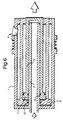
- a typical approximated force / stroke diagram for a single stage compact ram such as is schematically shown in Fig 1a appears in Fig. 1b.
- the thrust efficiency expressed as the equivalent average force divided by the peak force, is summarised in Table 1, together with the energy efficiency expressed as the expansion work done by the gas divided by the total energy available from adiabatic expansion of the gas to zero relative pressure.
- the importance of the peak force is that it is usually limited by the physical properties of the item being ejected or the allowable reaction force which can be tolerated by the launch platform.
- Energy efficiency is important in achieving a high ejection mass final velocity from a given volume of compressed gas. Work done first portion (i.e.
- Telescopic piston assemblies are used to obtain greater ram stroke, and hence energy output, from a given actuator installed length.
- their lateral stiffness is good because, if the sequence of extension is unrestrained, the high initial gas pressure acts on the largest piston area first, and as the gas expands, its reduced pressure then acts on the smallest area. But for the same reasons the thrust and energy efficiencies are poor. Nonetheless, a modest increase in energy output/installed length is obtained.
- the results are of the general form shown in Fig. 3b and Table 3.
- Ejector rams have been designed, especially for use with 'hot gas' (i.e. as generated by a pyrotechnic gas generator or 'cartridge'), to ensure that the highest pressure acts upon the smallest area first, (see UK patent GB 2 078 912 B and Fig. 4a herein) but even this is an incomplete solution because eventually, the volume masked from the high pressure gas during the first stage of ram extension is suddenly exposed to the gas, and the resultant expansion and depressurisation negates much of the advantage of having a larger working area during the second stage. Again, a further modest improvement in energy output is obtained, but the resultant force / stroke characteristic is still far from ideal, and is shown in Fig 4b and Table 4.
- the invention provides a piston assembly comprising an inner component, an intermediate component and an outer component, all telescopingly interfitted together, the intermediate component making a sliding seal with the inner component, characterised in that the inner component comprises a fluid outlet at one end; the intermediate component comprising a closed end surrounding the inner component fluid outlet end, the outer component making a first sliding seal with the intermediate component and a second sliding seal with the inner component; a detent being operative to hold the outer component in an extended position relative to the inner component.
- This arrangement can offer a reduced size gas storage volume, and/or a significant improvement in energy efficiency compared with conventional art, by providing a more sustained thrust from the extending 'ram' in a manner which will be described hereunder. This may be achieved without compromise to the structural efficiency of the ram assembly under the influence of lateral forces during extension.
- a feature of this invention is to provide the benefits of high gas pressure acting on a small area, followed by a lower pressure acting on a larger area, but without the intermediate expansion (as in Fig. 4a) which degrades the second stage starting pressure to an excessive extent, and without exposing the slenderest piston first.
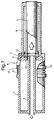
- a housing 1 provides structural support for the moving components and features a fixed inner component in the form of a gas entry sleeve 2 whose purpose is inter alia to carry high pressure gas to the end of the intermediate component, i.e. a hollow piston 3.
- a latching system 4 forming the detent for the outer component or hollow cylinder 6.
- the area on which gas initially acts is defined by the outer diameter of the entry sleeve 2, which engages on a sliding gas seal 5 in the inner wall of the piston 3 to contain the gas during the first stage of telescopic extension.
- the cylinder 6 is sealed to the entry sleeve 2 by a sliding gas seal 13 so that relative movement between piston 3 and cylinder 6 will tend to create a partial vacuum in the sealed space between these components, with the result that atmospheric pressure acting on the left hand end of cylinder 6 as illustrated in Fig. 6 will cause it to tend to move with the piston 3 as desired. This movement may be satisfactory under ideal conditions with low frictional forces, lightweight moving components and low ram extension speeds.
- the hollow piston 3 is latched to the cylinder 6 so that said cylinder is reliably transported with the piston during the first stage of extension.
- a series of radial latching elements 7 engage in a triangular sectioned groove made in the internal diameter of the cylinder, and are prevented from disengaging before the end of the first extension stage by the outer diameter of the gas entry sleeve 2. In this way, the piston 3 and the cylinder 6 move as a single assembly during the first stage.
- the latching elements 7 clear the entry sleeve 2 and are free to move toward the centre of the piston, thereby releasing the piston 3 from the cylinder 6.
- seal 5 clears the entry sleeve 2, allowing gas to enter the gap between the larger end of the piston 3 and the adjacent face of the cylinder 6 end, thereby applying an end load on these two components, attempting to separate them.
- the cylinder 6, however, is prevented from moving in a reverse direction by multiple pivoting dogs 8 of the latching system 4 (only one dog shown) which have engaged the cylinder 6 right hand end under the action of a spring 9 and collar 10 as the cylinder 6 is arrested by a resilient buffer 11.
- the dogs 8 are distributed about the circumference of the housing 1.
- the gas is now contained by the piston 3, the sleeve 2, the seal 12 on the piston outer diameter and the seal 13 between the cylinder 6 and the sleeve 2 outer diameter.
- the piston 3 is free to continue its movement and travels the length of the cylinder 6 bore under the motivation provided by the gas acting now on the larger diameter of the piston head.
- the final position of the components is depicted in Fig. 8 in which the piston head 14 contacts a buffer 15 in the right hand end of the cylinder 6.
- Table 10 summarises the performance characteristics of each of the described prior art piston designs and the Figs. 6-8 embodiment for comparison.
Applications Claiming Priority (2)
| Application Number | Priority Date | Filing Date | Title |
|---|---|---|---|
| GB9804701 | 1998-03-05 | ||
| GB9804701A GB2335004B (en) | 1998-03-05 | 1998-03-05 | Telescopic piston |
Publications (2)
| Publication Number | Publication Date |
|---|---|
| EP0940584A2 true EP0940584A2 (de) | 1999-09-08 |
| EP0940584A3 EP0940584A3 (de) | 2000-05-03 |
Family
ID=10828045
Family Applications (1)
| Application Number | Title | Priority Date | Filing Date |
|---|---|---|---|
| EP99301402A Withdrawn EP0940584A3 (de) | 1998-03-05 | 1999-02-25 | Teleskopischer Zylinder |
Country Status (4)
| Country | Link |
|---|---|
| US (1) | US6234062B1 (de) |
| EP (1) | EP0940584A3 (de) |
| GB (1) | GB2335004B (de) |
| IL (1) | IL128708A (de) |
Cited By (10)
| Publication number | Priority date | Publication date | Assignee | Title |
|---|---|---|---|---|
| DE19954577C1 (de) * | 1999-11-12 | 2001-06-21 | Hyco Pacoma Gmbh | Liftzylindereinheit für eine Hebebühne |
| WO2004007975A1 (en) * | 2002-07-11 | 2004-01-22 | Autoliv Asp, Inc. | Linear actuator |
| US7063019B2 (en) | 2002-07-11 | 2006-06-20 | Autoliv Asp, Inc. | Assemblies including extendable, reactive charge-containing actuator devices |
| US7182191B2 (en) | 2002-07-11 | 2007-02-27 | Autoliv Asp, Inc. | Motion damper |
| DE102005051657A1 (de) * | 2005-10-28 | 2007-05-03 | GM Global Technology Operations, Inc., Detroit | Pyrotechnischer Aktuator |
| US7303040B2 (en) | 2004-05-18 | 2007-12-04 | Autolive Asp, Inc. | Active vehicle hood system and method |
| WO2015177355A1 (de) * | 2014-05-22 | 2015-11-26 | Sms Meer Gmbh | Vorrichtung in form einer kolbeneinheit und verfahren zu deren betrieb |
| EP2190586A4 (de) * | 2007-08-21 | 2016-02-24 | Agco Corp | Integrierte abrisszylinder und verfahren zur konstruktion einer auslegeranordnung |
| DE102020108235A1 (de) | 2020-03-25 | 2021-09-30 | Prominent Gmbh | Hydraulikelement und Verdrängerpumpe mit einem solchen |
| IL274262A (en) * | 2020-04-26 | 2021-10-31 | Rafael Advanced Defense Systems Ltd | Pneumatic launcher |
Families Citing this family (9)
| Publication number | Priority date | Publication date | Assignee | Title |
|---|---|---|---|---|
| CA2415982C (en) * | 2003-01-09 | 2008-11-18 | Industries Mailhot Inc. | A bore sealing telescopic hoist |
| DE10302501A1 (de) * | 2003-01-23 | 2004-08-05 | Roche Diagnostics Gmbh | Vorrichtung und Verfahren zur Aufnahme einer Körperflüssigkeit für Analysezwecke |
| CN101100272A (zh) * | 2006-07-04 | 2008-01-09 | 现代自动车株式会社 | 用于将车轮安装至车辆的篮式装置 |
| US7597038B2 (en) * | 2007-01-31 | 2009-10-06 | The Boeing Company | Load reducing stores launch tube |
| US8297165B2 (en) | 2007-01-31 | 2012-10-30 | The Boeing Company | Load reducing stores launch tube |
| WO2008125110A2 (en) * | 2007-04-16 | 2008-10-23 | Falck Schmidt Defence Systems A/S | Telescoping mast |
| ITBS20080180A1 (it) * | 2008-10-14 | 2010-04-15 | Tecnomac Srl | Dispositivo generatore di energia elettrica da fonte rinnovabile |
| CN106460884A (zh) * | 2014-05-08 | 2017-02-22 | Tk控股公司 | 用于烟火致动器的多用途且可调整压力室 |
| GB2530762B (en) * | 2014-09-30 | 2017-05-31 | Edo Mbm Tech Ltd | Retractable telescopic piston |
Citations (2)
| Publication number | Priority date | Publication date | Assignee | Title |
|---|---|---|---|---|
| GB2078912A (en) | 1979-06-04 | 1982-01-13 | Nash Frazer Ltd | Missile launcher |
| US4850553A (en) | 1986-09-12 | 1989-07-25 | Scot, Incorporated | Ejector arrangement for aircraft store racks |
Family Cites Families (14)
| Publication number | Priority date | Publication date | Assignee | Title |
|---|---|---|---|---|
| US668321A (en) * | 1900-04-26 | 1901-02-19 | Dental Mfg Co Ltd | Seat raising or lowering mechanism for dental chairs. |
| US1799298A (en) * | 1929-01-25 | 1931-04-07 | Walker Mfg Co | Hydraulic lifting jack |
| US3010752A (en) * | 1957-11-29 | 1961-11-28 | Geffner Ted | Ejection bolt mechanism |
| GB1003691A (en) * | 1960-12-07 | 1965-09-08 | Sidler Ltd | Improvements in or relating to hydraulic rams |
| US3426651A (en) * | 1966-07-26 | 1969-02-11 | Pneumo Dynamics Corp | Air-oil suspension |
| US3614912A (en) * | 1969-09-29 | 1971-10-26 | Lionel Pacific Inc | Telescoping piston central lock hydraulic actuator |
| US3958376A (en) * | 1974-02-15 | 1976-05-25 | Zip Up, Inc. | Extendible tower structure |
| US4075929A (en) * | 1976-01-28 | 1978-02-28 | The United States Of America As Represented By The Secretary Of The Air Force | Three stage thrusting device |
| DE2701895C2 (de) * | 1976-03-09 | 1984-05-24 | R. Alkan & Cie, 94460 Valenton | Ausstoßer einer Flugzeuglast-Abwerfvorrichtung |
| US4388853A (en) * | 1980-07-24 | 1983-06-21 | Frazer-Nash Limited | Missile launchers |
| US4466334A (en) * | 1982-03-09 | 1984-08-21 | The United States Of America As Represented By The Secretary Of The Navy | Hydraulic aircraft/stores cartridge |
| SE434535B (sv) * | 1982-12-15 | 1984-07-30 | Electrolux Ab | Manoverdon vid med vakuum arbetande transportsystem for vetskor, foretredesvis vakuumavloppssystem |
| US5850713A (en) * | 1996-12-20 | 1998-12-22 | Yuasa Koki Co., Ltd | Device raising and lowering apparatus |
| US6073886A (en) * | 1998-08-20 | 2000-06-13 | Mcdonnell Douglas Corporation | Constant pressure area telescoping piston and method of using same |
-
1998
- 1998-03-05 GB GB9804701A patent/GB2335004B/en not_active Expired - Fee Related
-
1999
- 1999-02-24 IL IL12870899A patent/IL128708A/xx not_active IP Right Cessation
- 1999-02-25 EP EP99301402A patent/EP0940584A3/de not_active Withdrawn
- 1999-03-02 US US09/260,753 patent/US6234062B1/en not_active Expired - Fee Related
Patent Citations (2)
| Publication number | Priority date | Publication date | Assignee | Title |
|---|---|---|---|---|
| GB2078912A (en) | 1979-06-04 | 1982-01-13 | Nash Frazer Ltd | Missile launcher |
| US4850553A (en) | 1986-09-12 | 1989-07-25 | Scot, Incorporated | Ejector arrangement for aircraft store racks |
Cited By (15)
| Publication number | Priority date | Publication date | Assignee | Title |
|---|---|---|---|---|
| US6378412B1 (en) | 1999-11-12 | 2002-04-30 | Kurt Wittich | Lifting cylinder unit for a lifting platform |
| DE19954577C1 (de) * | 1999-11-12 | 2001-06-21 | Hyco Pacoma Gmbh | Liftzylindereinheit für eine Hebebühne |
| WO2004007975A1 (en) * | 2002-07-11 | 2004-01-22 | Autoliv Asp, Inc. | Linear actuator |
| US6907817B2 (en) | 2002-07-11 | 2005-06-21 | Autoliv Asp, Inc. | Linear actuator |
| US7063019B2 (en) | 2002-07-11 | 2006-06-20 | Autoliv Asp, Inc. | Assemblies including extendable, reactive charge-containing actuator devices |
| US7182191B2 (en) | 2002-07-11 | 2007-02-27 | Autoliv Asp, Inc. | Motion damper |
| US7303040B2 (en) | 2004-05-18 | 2007-12-04 | Autolive Asp, Inc. | Active vehicle hood system and method |
| DE102005051657A1 (de) * | 2005-10-28 | 2007-05-03 | GM Global Technology Operations, Inc., Detroit | Pyrotechnischer Aktuator |
| US8549975B2 (en) | 2005-10-28 | 2013-10-08 | GM Global Technology Operations LLC | Pyrotechnic actuator with a cylinder having communicating chambers |
| US8596180B2 (en) | 2005-10-28 | 2013-12-03 | GM Global Technology Operations LLC | Pyrotechnic actuator with a cylinder having communicating chambers |
| EP2190586A4 (de) * | 2007-08-21 | 2016-02-24 | Agco Corp | Integrierte abrisszylinder und verfahren zur konstruktion einer auslegeranordnung |
| WO2015177355A1 (de) * | 2014-05-22 | 2015-11-26 | Sms Meer Gmbh | Vorrichtung in form einer kolbeneinheit und verfahren zu deren betrieb |
| DE102020108235A1 (de) | 2020-03-25 | 2021-09-30 | Prominent Gmbh | Hydraulikelement und Verdrängerpumpe mit einem solchen |
| IL274262A (en) * | 2020-04-26 | 2021-10-31 | Rafael Advanced Defense Systems Ltd | Pneumatic launcher |
| WO2021220129A1 (en) * | 2020-04-26 | 2021-11-04 | Rafael Advanced Defense Systems Ltd. | Pneumatic actuator |
Also Published As
| Publication number | Publication date |
|---|---|
| IL128708A (en) | 2001-08-26 |
| GB9804701D0 (en) | 1998-04-29 |
| IL128708A0 (en) | 2000-01-31 |
| US6234062B1 (en) | 2001-05-22 |
| GB2335004A (en) | 1999-09-08 |
| EP0940584A3 (de) | 2000-05-03 |
| GB2335004B (en) | 2002-02-27 |
Similar Documents
| Publication | Publication Date | Title |
|---|---|---|
| EP0940584A2 (de) | Teleskopischer Zylinder | |
| CA1287699C (en) | Indirect firing fastener driving tool | |
| US5114095A (en) | Arrangement for the unlatching and extension of the stabilizing fins of a projectile | |
| US4091621A (en) | Pyrotechnic piston actuator | |
| US6073886A (en) | Constant pressure area telescoping piston and method of using same | |
| CN108519028B (zh) | 爆炸分离螺栓 | |
| US4817496A (en) | Firearm | |
| GB2312659A (en) | Buffers | |
| CN109436286A (zh) | 一种用于冲压空气涡轮的变刚度弹力释放作动装置 | |
| US6492632B1 (en) | Lock and slide mechanism for tube launched projectiles | |
| US7571610B2 (en) | Extendible exhaust nozzle bell for a rocket engine | |
| US4753151A (en) | Self-retracting ballistic actuator system | |
| JPH115600A (ja) | ブースタロケットの結合装置 | |
| EP3201477B1 (de) | Einfahrbar teleskopischer stellantrieb mit auslösbaren verriegelungsmitteln | |
| US3656781A (en) | Quick-disconnect coupling | |
| US3442179A (en) | Double-acting explosive actuator | |
| EP1056570B1 (de) | Kraftbetriebenes werkzeug mit kolben mit automatischem zurückfahren des kolbens | |
| US6655569B1 (en) | Power actuated tool and shroud for use with the tool | |
| RU2246025C1 (ru) | Раздвижное сопло ракетного двигателя | |
| CN216000392U (zh) | 一种射钉器发射管组件 | |
| CN110986675A (zh) | 多级活塞缸式裸弹燃气弹射装置和方法 | |
| CN219666513U (zh) | 一种管夹撑开装置 | |
| CN215333737U (zh) | 一种活塞式液压缸缓冲机构 | |
| RU2309283C1 (ru) | Раздвижное сопло ракетного двигателя | |
| CN113551564B (zh) | 一种可径向收缩的弹射装置锥形缓冲止动尾罩结构 |
Legal Events
| Date | Code | Title | Description |
|---|---|---|---|
| PUAI | Public reference made under article 153(3) epc to a published international application that has entered the european phase |
Free format text: ORIGINAL CODE: 0009012 |
|
| AK | Designated contracting states |
Kind code of ref document: A2 Designated state(s): DE FR IT |
|
| AX | Request for extension of the european patent |
Free format text: AL;LT;LV;MK;RO;SI |
|
| PUAL | Search report despatched |
Free format text: ORIGINAL CODE: 0009013 |
|
| AK | Designated contracting states |
Kind code of ref document: A3 Designated state(s): AT BE CH CY DE DK ES FI FR GB GR IE IT LI LU MC NL PT SE |
|
| AX | Request for extension of the european patent |
Free format text: AL;LT;LV;MK;RO;SI |
|
| 17P | Request for examination filed |
Effective date: 20001101 |
|
| AKX | Designation fees paid |
Free format text: FR GB IT |
|
| RBV | Designated contracting states (corrected) |
Designated state(s): DE FR IT |
|
| REG | Reference to a national code |
Ref country code: DE Ref legal event code: 8566 |
|
| RAP1 | Party data changed (applicant data changed or rights of an application transferred) |
Owner name: MBM TECHNOLOGY LIMITED |
|
| GRAP | Despatch of communication of intention to grant a patent |
Free format text: ORIGINAL CODE: EPIDOSNIGR1 |
|
| STAA | Information on the status of an ep patent application or granted ep patent |
Free format text: STATUS: THE APPLICATION IS DEEMED TO BE WITHDRAWN |
|
| 18D | Application deemed to be withdrawn |
Effective date: 20031219 |