EP0940164B1 - Procédé de séparation par adsorption d'un mélange gazeux - Google Patents
Procédé de séparation par adsorption d'un mélange gazeux Download PDFInfo
- Publication number
- EP0940164B1 EP0940164B1 EP99400500A EP99400500A EP0940164B1 EP 0940164 B1 EP0940164 B1 EP 0940164B1 EP 99400500 A EP99400500 A EP 99400500A EP 99400500 A EP99400500 A EP 99400500A EP 0940164 B1 EP0940164 B1 EP 0940164B1
- Authority
- EP
- European Patent Office
- Prior art keywords
- adsorber
- cycle
- process according
- pressure
- way valve
- Prior art date
- Legal status (The legal status is an assumption and is not a legal conclusion. Google has not performed a legal analysis and makes no representation as to the accuracy of the status listed.)
- Expired - Lifetime
Links
- 238000000034 method Methods 0.000 title claims description 22
- 238000001179 sorption measurement Methods 0.000 title claims description 20
- 230000008569 process Effects 0.000 title claims description 19
- 239000000203 mixture Substances 0.000 title claims description 5
- 238000004891 communication Methods 0.000 claims description 8
- 230000006835 compression Effects 0.000 claims description 7
- 238000007906 compression Methods 0.000 claims description 7
- 238000003860 storage Methods 0.000 claims description 2
- 238000004519 manufacturing process Methods 0.000 description 37
- 238000009434 installation Methods 0.000 description 30
- 239000001301 oxygen Substances 0.000 description 24
- 229910052760 oxygen Inorganic materials 0.000 description 24
- QVGXLLKOCUKJST-UHFFFAOYSA-N atomic oxygen Chemical compound [O] QVGXLLKOCUKJST-UHFFFAOYSA-N 0.000 description 23
- 238000010586 diagram Methods 0.000 description 15
- 239000007789 gas Substances 0.000 description 11
- 238000010926 purge Methods 0.000 description 10
- 230000006837 decompression Effects 0.000 description 7
- 238000010828 elution Methods 0.000 description 7
- 230000004048 modification Effects 0.000 description 7
- 238000012986 modification Methods 0.000 description 7
- 239000003463 adsorbent Substances 0.000 description 6
- 230000001052 transient effect Effects 0.000 description 6
- 238000005265 energy consumption Methods 0.000 description 5
- 238000005086 pumping Methods 0.000 description 5
- XXONZJKORUUFIZ-UHFFFAOYSA-N 3-sulfanylpyridine-2-sulfonamide Chemical compound NS(=O)(=O)C1=NC=CC=C1S XXONZJKORUUFIZ-UHFFFAOYSA-N 0.000 description 4
- 230000007704 transition Effects 0.000 description 4
- 238000013022 venting Methods 0.000 description 4
- 241000196324 Embryophyta Species 0.000 description 3
- 230000000694 effects Effects 0.000 description 3
- 235000021183 entrée Nutrition 0.000 description 3
- 239000008246 gaseous mixture Substances 0.000 description 3
- 238000000926 separation method Methods 0.000 description 3
- 239000003990 capacitor Substances 0.000 description 2
- 238000009826 distribution Methods 0.000 description 2
- 239000002245 particle Substances 0.000 description 2
- XLYOFNOQVPJJNP-UHFFFAOYSA-N water Substances O XLYOFNOQVPJJNP-UHFFFAOYSA-N 0.000 description 2
- 240000008042 Zea mays Species 0.000 description 1
- 230000009286 beneficial effect Effects 0.000 description 1
- 238000007796 conventional method Methods 0.000 description 1
- 230000003247 decreasing effect Effects 0.000 description 1
- 230000009977 dual effect Effects 0.000 description 1
- 239000012530 fluid Substances 0.000 description 1
- 230000006872 improvement Effects 0.000 description 1
- 239000012535 impurity Substances 0.000 description 1
- 230000033001 locomotion Effects 0.000 description 1
- 150000002926 oxygen Chemical class 0.000 description 1
- 230000036284 oxygen consumption Effects 0.000 description 1
- 230000002028 premature Effects 0.000 description 1
- 230000009467 reduction Effects 0.000 description 1
- 230000008929 regeneration Effects 0.000 description 1
- 238000011069 regeneration method Methods 0.000 description 1
- 238000011160 research Methods 0.000 description 1
- 238000010079 rubber tapping Methods 0.000 description 1
- 239000013589 supplement Substances 0.000 description 1
- 238000011144 upstream manufacturing Methods 0.000 description 1
Images


Classifications
-
- B—PERFORMING OPERATIONS; TRANSPORTING
- B01—PHYSICAL OR CHEMICAL PROCESSES OR APPARATUS IN GENERAL
- B01D—SEPARATION
- B01D53/00—Separation of gases or vapours; Recovering vapours of volatile solvents from gases; Chemical or biological purification of waste gases, e.g. engine exhaust gases, smoke, fumes, flue gases, aerosols
- B01D53/02—Separation of gases or vapours; Recovering vapours of volatile solvents from gases; Chemical or biological purification of waste gases, e.g. engine exhaust gases, smoke, fumes, flue gases, aerosols by adsorption, e.g. preparative gas chromatography
- B01D53/04—Separation of gases or vapours; Recovering vapours of volatile solvents from gases; Chemical or biological purification of waste gases, e.g. engine exhaust gases, smoke, fumes, flue gases, aerosols by adsorption, e.g. preparative gas chromatography with stationary adsorbents
- B01D53/0407—Constructional details of adsorbing systems
- B01D53/0446—Means for feeding or distributing gases
-
- B—PERFORMING OPERATIONS; TRANSPORTING
- B01—PHYSICAL OR CHEMICAL PROCESSES OR APPARATUS IN GENERAL
- B01D—SEPARATION
- B01D53/00—Separation of gases or vapours; Recovering vapours of volatile solvents from gases; Chemical or biological purification of waste gases, e.g. engine exhaust gases, smoke, fumes, flue gases, aerosols
- B01D53/02—Separation of gases or vapours; Recovering vapours of volatile solvents from gases; Chemical or biological purification of waste gases, e.g. engine exhaust gases, smoke, fumes, flue gases, aerosols by adsorption, e.g. preparative gas chromatography
- B01D53/04—Separation of gases or vapours; Recovering vapours of volatile solvents from gases; Chemical or biological purification of waste gases, e.g. engine exhaust gases, smoke, fumes, flue gases, aerosols by adsorption, e.g. preparative gas chromatography with stationary adsorbents
- B01D53/047—Pressure swing adsorption
-
- B—PERFORMING OPERATIONS; TRANSPORTING
- B01—PHYSICAL OR CHEMICAL PROCESSES OR APPARATUS IN GENERAL
- B01D—SEPARATION
- B01D2256/00—Main component in the product gas stream after treatment
- B01D2256/12—Oxygen
-
- B—PERFORMING OPERATIONS; TRANSPORTING
- B01—PHYSICAL OR CHEMICAL PROCESSES OR APPARATUS IN GENERAL
- B01D—SEPARATION
- B01D2257/00—Components to be removed
- B01D2257/10—Single element gases other than halogens
- B01D2257/102—Nitrogen
-
- B—PERFORMING OPERATIONS; TRANSPORTING
- B01—PHYSICAL OR CHEMICAL PROCESSES OR APPARATUS IN GENERAL
- B01D—SEPARATION
- B01D2259/00—Type of treatment
- B01D2259/40—Further details for adsorption processes and devices
- B01D2259/40003—Methods relating to valve switching
-
- B—PERFORMING OPERATIONS; TRANSPORTING
- B01—PHYSICAL OR CHEMICAL PROCESSES OR APPARATUS IN GENERAL
- B01D—SEPARATION
- B01D2259/00—Type of treatment
- B01D2259/40—Further details for adsorption processes and devices
- B01D2259/40011—Methods relating to the process cycle in pressure or temperature swing adsorption
- B01D2259/40058—Number of sequence steps, including sub-steps, per cycle
- B01D2259/40066—Six
-
- B—PERFORMING OPERATIONS; TRANSPORTING
- B01—PHYSICAL OR CHEMICAL PROCESSES OR APPARATUS IN GENERAL
- B01D—SEPARATION
- B01D2259/00—Type of treatment
- B01D2259/40—Further details for adsorption processes and devices
- B01D2259/403—Further details for adsorption processes and devices using three beds
-
- B—PERFORMING OPERATIONS; TRANSPORTING
- B01—PHYSICAL OR CHEMICAL PROCESSES OR APPARATUS IN GENERAL
- B01D—SEPARATION
- B01D53/00—Separation of gases or vapours; Recovering vapours of volatile solvents from gases; Chemical or biological purification of waste gases, e.g. engine exhaust gases, smoke, fumes, flue gases, aerosols
- B01D53/02—Separation of gases or vapours; Recovering vapours of volatile solvents from gases; Chemical or biological purification of waste gases, e.g. engine exhaust gases, smoke, fumes, flue gases, aerosols by adsorption, e.g. preparative gas chromatography
- B01D53/04—Separation of gases or vapours; Recovering vapours of volatile solvents from gases; Chemical or biological purification of waste gases, e.g. engine exhaust gases, smoke, fumes, flue gases, aerosols by adsorption, e.g. preparative gas chromatography with stationary adsorbents
- B01D53/047—Pressure swing adsorption
- B01D53/053—Pressure swing adsorption with storage or buffer vessel
Definitions
- the present invention relates to a method of separation by adsorption of a gaseous mixture in at least one adsorber by setting of a pressure variation cycle comprising a succession of steps by means of at least one compression machine.
- the invention applies in particular to the production of oxygen from air atmospheric and, in the following, reference will be made to this application as preferential example.
- One of the ways to reduce the cost of production of oxygen by PSA is to decrease substantially investment by maintaining energy consumption constant.
- FIG. 1 schematically represents an example of a PSA installation of oxygen production from atmospheric air.
- This installation comprises: a blower 1; three adsorbers A1 to A3; a line 2 for supplying the adsorbers with air, which connects the discharge of the fan to the lower ends or adsorber entrances via respective valves V11 to V13; a vacuum pump 3 whose backflow is connected to the surrounding atmosphere; a line 4 evacuation that connects the suction of the vacuum pump to the adsorber inputs via respective valves V21 to V23; and a line 5 of oxygen circulation connected to the end upper or outlet of each adsorber by two taps in parallel: respective connections 6-1 to 6-3 equipped with respective valves V31 to V33, for the production of oxygen, and respective connections 7-1 to 7-3, equipped with valves respectively V41 to V43, for the repressurization of adsorber.
- Line 5 is also connected to a circuit of oxygen consumption schematized in 8.
- the installation also comprises means, known per se and not shown, control, regulation and power supply, adapted to perform the cycle shown in Figure 2.
- Figure 2 is a diagram that illustrates a cycle typical adsorption process carried out by means of the installation of Figure 1.
- the current enters the adsorber through the inlet end of the adsorber; if the upwardly directed arrow is above the pressure line, the stream exits the adsorber through the outlet end of the adsorber, the inlet and outlet ends being respectively those of the adsorber gas to be treated and gas withdrawn during the production phase; when an arrow is in the direction of decreasing ordinates (towards the bottom of the diagram), the current is said against the current, in the adsorber.
- the stream exits the adsorber through the inlet end of the adsorber; if the downward arrow is above the pressure line, the current enters the adsorber through the outlet end of the adsorber, the inlet and outlet ends always being those of the gas at the outlet. process and gas withdrawn during the production phase.
- FIG. 3 The diagram of FIG. 3, where the time t is plotted on the abscissa and the pressure P on the ordinate, illustrates and makes it possible to clearly understand this evolution. Indeed, in the vicinity of the switching of the vacuum pump from one adsorber to another, that is to say in the vicinity of instants T / 3, 2T / 3 and T, there is a distortion of the curve actual C1 with respect to the theoretical curve C2. More precisely, in this FIG. 3, the duration x corresponds to the closing time of the valves V2i (V21 in the example), and the duration y to the opening of the valves V2 (i + 1) (V22 in the example) . These times are of the order of 0.5 to 2 seconds depending on the size of the valves.
- valves V21, V22 and V23 are different from the valves used for the 3 x 90s cycle.
- the object of the invention is to eliminate, or at least reduce, important, the extra energy cost during these transitional phases.
- the subject of the invention is a method according to claim 1.
- GB-A-2 053 020 discloses a dehumidifier with two adsorbers, with regeneration by circulation of dry gas starting with a balancing phase between the dry gas outlet ends of the adsorbers.
- An installation separation by adsorption of a gaseous mixture, in particular atmospheric air, for carrying out the process according to the invention comprises at least one adsorber and means to implement in it a cycle of pressure variation, these means comprising a machine for compression and selective linking means of at least a terminal of this machine to a first space and to a second space, and also includes control means which, at certain predetermined times, put the said terminal simultaneously in communication with the first space and with the second space.
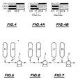
- FIGS. 4, 4A, 4B in which the open state of the valves is shown in white and their state closed in gray.
- the purge step (b) is carried out, from T3 to 2T / 3, with the valve V21 open while the valves V22 and V23 are closed.
- time 2T / 3 at times x and y close, we close V21 and opens V22 ( Figure 4).
- the suction of the vacuum pump is permanently connected to at least one adsorber, including during the switching phases from one adsorber to another.
- the vacuum pump does not pump at any time on the only evacuation line 4, and its aspiration is constantly finds pressure close to the pressure theoretical corresponding to a maneuver of the valves infinitely fast.
- valve V41 can also be open before 2T / 3, especially at t1.
- the Countercurrent repressurization with oxygen begins then in A1, simultaneously with the first co-current repressurization with air. This allows to limit the negative effects that may cycle, the introduction of air at too low a pressure into a adsorber as to the advance of the impurity front in the adsorbents.
- FIGS. 5 to 7 illustrate schematically the corresponding sequence of operations, which is understood immediately at the sight of these figures and explanations which precede.
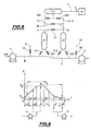
- the installation represented as an example on the Figure 8 is of the MPSA type with two adsorbers A1 and A2.
- the installation also includes a 9 tapping venting the discharge of the compressor 1, equipped with a valve V5, and a quilting 10 of venting the suction of the vacuum pump 3, equipped with a V6 valve.
- the exits adsorbers are connected in parallel with one another balancing line 11 provided with a valve V7 and by a elution conduit 12 provided with a valve V8.
- these outputs are connected to a buffer capacity 12 by respective pipes 13-1 and 13-2 equipped with valves respective V91 and V92.
- the capacity 12 makes it possible to ensure Oxygen production continuously at the pressure PM.
- Figure 9 represents a similar way to the Figure 2 a classic cycle implemented using this installation, between the high pressure PM, typically from the order of 1.5 bar, and a low pressure Pm, typically of the order of 400 mbar.
- a constant flow of oxygen is withdrawn from the capacity 12 as a production flow.
- the Air compressor 1 is not used.
- the compressed flow is vented through the V5 valve.
- the energy consumption of the machine is then minimal.
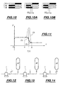
- step (b) we observe the transition from step (b) to step (c1), for reasons similar to what has been explained above, energy overconsumption.
- the normal sequence ( Figure 10) consists of close valve V11 then open valve V5. Thereby, line 2, of small volume relative to the adsorbers, Compressed at a pressure greater than the pressure normal service.
- the valve is opened V5 before closing valve V11, as shown in Figure 10A.
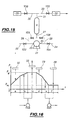
- Figures 15 to 22A illustrate the application of the invention to an installation of the monoadsorbeur type.
- This installation essentially comprises: single adsorber A; a compression machine 21 to a single direction of rotation forming both air compressor and vacuum pump; an air inlet pipe 22 connected to a terminal 23 of the machine 21 and equipped with a valve V22; a exhaust pipe 24 connected to the other terminal 25 of the machine and equipped with a V24 valve; a pipe 26 equipped a valve V26, connecting the terminal 23 to the lower entrance 27 of the adsorber; a pipe 28 equipped with a valve V28, connecting terminal 25 to entry 27; an elution capacity 29; an elution line 30 equipped with a valve V30 and connecting the capacity 29 to the top outlet 31 of the adsorber; production capacity 32; and driving 33 equipped with a valve V33 and connecting the 32 capacity at exit 32.
- a constant flow of oxygen is withdrawn from the capacity 32 as a throughput.
- the maneuvering mode of the valves described above in the case of several cycles and installations particulars can apply to all PSA units, MPSA or PSA having any number of adsorbers N ⁇ 1. It can be used, in general, to avoid over-consumption of energy when switching a compression machine (compressor, blower or pump vacuum) from one adsorber to another adsorber or from from adsorber to the surrounding atmosphere or vice versa.
- a compression machine compressor, blower or pump vacuum
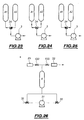
- This mode of maneuver can be achieved by means of of a three-way valve, as shown in FIGS. at 25 in the case of switching a vacuum pump a adsorber A1 (FIG. 23) to another adsorber A2 (FIG. 25). For this, during an intermediate stage of the switching, the three channels of the valve are opened ( Figure 24).
- Figure 26 illustrates similarly the use of two three-way valves in the case of installing the Figure 15, for switching the machine 21 between the adsorber and the surrounding atmosphere, in place of on the one hand valves V22 and V26 (three-way valve 35), and on the other hand valves V24 and V28 (three-way valve 36).
- valve three-way any type of fluid dispenser allowing, in one of its service positions, the in simultaneous communication of the three spaces that it connects, and, in two other service positions, placing one of these three spaces in communication with one or the other of the other two spaces.
- Such a distributor may in particular be constituted by a three-way valve proper, or by a three-way distributor with sliding or rotating drawer.
- the opening-closing sequences of the invention may also be beneficial, although for other reasons, when switching a compressor of oxygen 37, for example as shown in FIG. from one adsorber to another by operation of valves V4i.
- the premature opening of the second valve of production avoids the depression of the aspiration of this compressor, and therefore the risks of air intake and of humidity in the oxygen circuit.
Description
- les cycles dits VSA (Vaccum Swing Adsorption), dans lesquels l'adsorption s'effectue sensiblement à la pression atmosphérique et la pression minimale du cycle est nettement inférieure à cette pression atmosphérique et typiquement de l'ordre de 250 à 400 mbar. Ces cycles sont généralement mis en oeuvre au moyen d'unités à trois adsorbeurs.
- les cycles transatmosphériques dits MPSA, qui diffèrent des précédents par le fait que l'adsorption s'effectue à une pression nettement supérieure à la pression atmosphérique et typiquement de l'ordre de 1,3 à 2 bars. Ces cycles sont généralement mis en oeuvre au moyen d'unités à deux adsorbeurs.
- les cycles dits PSA (Pressure Swing Adsorption), dans lesquels l'adsorption s'effectue à une pression nettement supérieure à la pression atmosphérique, typiquement de l'ordre de 3 à 8 bars, tandis que la pression minimale du cycle est sensiblement égale à la pression atmosphérique.
Le procédé suivant invention peut comporter une ou plusieurs des caractéristiques suivantes :
- la durée de ladite opération intermédiaire est au plus égale au tiers, et de préférence comprise entre 1/3 et 1/50ème, de la plus courte des étapes du cycle qu'elle relie ;
- l'un desdits espaces est un volume de mélange gazeux à séparer, typiquement l'atmosphère environnante ;
- l'un au moins desdits espaces est une capacité de stockage de gaz;
- l'un au moins desdits espaces est un premier adsorbeur qui, pendant ladite opération intermédiaire, communique avec la machine par l'une de ses extrémités;
- pendant ladite opération intermédiaire, ledit premier adsorbeur est également mis en communication avec un troisième espace par son autre extrémité ;
- ledit troisième espace est un autre adsorbeur qui se trouve à une pression différente de celle dudit premier adsorbeur;
- la machine est une soufflante ou un compresseurd d'air, ou une pompe à vide à une seule fonction;
- la machine est adaptée pour fonctionner en compresseur d'air ou en pompe à vide suivant les étapes du cycle;
- ladite commutation s'effectue par fermeture d'une première vanne deux-voies et ouverture d'une deuxième vanne deux-voies, et ladite opération intermédiaire par ouverture de la deuxième vanne deux-voies avant fermeture de la première vanne deux-voies ;
- ladite commutation s'effectue par fermeture d'une première voie d'une vanne trois-voies et ouverture d'une deuxième voie de cette vanne trois-voies, la troisième voie de cette vanne trois-voies étant ouverte, et ladite opération intermédiaire par ouverture de la deuxième voie de la vanne trois-voies avant la fermeture de ladite première voie.
- lesdits moyens de liaison sélective comprennent deux vannes deux-voies, et lesdits moyens de commande sont adaptés pour ouvrir simultanément les deux vannes deux-voies auxdits instants prédéterminés;
- lesdits moyens de liaison sélective comprennent une vanne trois-voies, et lesdits moyens de commande sont adaptés pour ouvrir simultanément les trois voies de cette vanne trois-voies.
- La Figure 1 représente schématiquement une installation VSA à trois adsorbeurs pour la production d'oxygène à partir d'air atmosphérique;
- la Figure 2 est un diagramme illustrant un cycle connu mis en oeuvre au moyen de cette installation;
- la Figure 2A est un diagramme analogue à la Figure 2 illustrant une première modification du cycle conforme à l'invention;
- La Figure 2B est un diagramme analogue illustrant une seconde modification du cycle conforme à l'invention;
- la Figure 3 est un diagramme qui illustre la variation de pression à l'aspiration de la pompe à vide, dans le cas du cycle connu et dans celui d'un cycle suivant l'invention;
- la Figure 4 est un schéma qui illustre la commutation des vannes pendant une phase transitoire, dans le cas de la Figure 2;
- les Figures 4A et 4B sont des schémas analogues qui correspondent respectivement aux Figures 2A et 2B;
- les Figures 5 à 7 sont des vues schématiques partielles qui illustrent d'une autre manière une phase transitoire suivant l'invention;
- la Figure 8 est une vue schématique d'une installation à deux adsorbeurs pour la production d'oxygène à partir d'air atmosphérique;
- la Figure 9 est un diagramme analogue à la Figure 2 qui illustre un cycle connu mis en oeuvre au moyen de l'installation de la Figure 8;
- la Figure 10 est un schéma analogue à la Figure 4 qui illustre la commutation des vannes pendant une phase transitoire du compresseur, dont le cycle de la Figure 9;
- les Figures 10A et 10B sont des schémas analogues correspondant respectivement à deux modifications du cycle conformes à l'invention;
- la Figure 11 est un diagramme analogue à la Figure 3 qui illustre le phénomène de surconsommation du compresseur pendant les phases transitoires dans le cycle de la Figure 9, ainsi que l'amélioration apportée par l'invention;
- les Figures 12 à 14 sont des vues schématiques analogues aux Figures 5 à 7 mais correspondant à l'installation de la Figure 8;
- la Figure 15 représente schématiquement une installation du type monoadsorbeur pour la production d'oxygène à partir d'air atmosphérique;
- la Figure 16 est un diagramme analogue à la Figure 2 qui illustre un cycle connu mis en oeuvre au moyen de l'installation de la Figure 15;
- les Figures 17 à 19 sont des vues schématiques partielles qui illustrent d'une autre manière la commutation classique des vannes à la fin de la phase de purge/élution;
- les Figures 17A à 19A sont des vues analogues correspondant à la mise en oeuvre de l'invention;
- les Figures 20 à 22 sont des vues analogues aux Figures 17 à 19 respectivement, illustrant la commutation classique des vannes à la fin de la phase d'adsorption;
- les Figures 20A à 22A sont des vues analogues correspondant à la mise en oeuvre de l'invention;
- les Figures 23 à 25 sont des vues schématiques partielles qui illustrent l'utilisation d'une vanne trois-voies pour assurer la commutation de la pompe à vide conforme à l'invention, dans le cas de l'installation de la Figure 8; et
- la Figure 26 représente l'utilisation de deux vannes trois-voies dans l'installation de la Figure 15 pour la mise en oeuvre de l'invention.
- De T/3 à t1 (Figure 5), la pompe à vide 3 n'est reliée qu'à l'adsorbeur A1. A l'instant t1, la pression dans A1 est sensiblement Pm, tandis que l'adsorbeur A2, qui termine l'étape (a) de production, est à la pression haute PM.
- De t1 à 2T/3 (Figure 6), la pompe à vide est reliée aux deux adsorbeurs A1 et A2. Il se produit donc une brève décompression à contre-courant de A2, à la fois vers A1, qui subit donc une brève première repressurisation à contre-courant, et vers la pompe à vide. Cette brève repressurisation est réalisée essentiellement avec de l'air contenu dans la zone d'entrée de l'adsorbeur A2, c'est-à-dire dans le volume libre de distribution situé à l'amont des adsorbants et dans les espaces libres du premier lit (ou de la première zone dans le cas d'un lit unique) servant à arrêter l'eau et le CO2 de l'eau. Les recherches menées par la demanderesse ont permis de constater que cette repressurisation partielle à l'air n'avait pas d'impact négatif sur les performances du cycle.
- A partir de l'instant 2T/3, la pompe à vide n'est reliée qu'à l'adsorbeur A2, qui est ainsi purgé.
- Pendant l'étape (f), les vannes V26 et V24 sont
ouvertes tandis que les vannes V22 et V28 sont fermées
(Figure 17). Puis :
- on ferme la vanne 26 (Figure 18), puis
- on ouvre la vanne 24, ce qui réalise la mise à l'air de la machine 21 (Figure 19).
- Pendant l'étape (c), les vannes V22 et V28 sont
ouvertes et les vannes V26 et V24 sont fermées (Figure 20).
Puis
- on ferme la vanne V28 (Figure 21), puis
- on ouvre la vanne V24, ce qui réalise la mise à l'air de la machine 21 (Figure 22).
Claims (13)
- Procédé se séparation par adsorption d'un mélange gazeux dans au moins un adsorbeur, par mise en oeuvre d'un cycle de variation de pression comportant une succession d'étapes au moyen d'au moins une machine de compression (1,3 ;21) ayant une borne sélectivement connectable à l'adsorbeur, procédé dans lequel, à au moins un instant du cycle, la bome de machine de compression (1,3;21) est commutée d'un premier espace qui se trouve à une première pression P1 à un deuxième espace qui se trouve à une deuxième pression P2 nettement différente de la première pression P1, et où ladite commutation comporte une opération intermédiaire dans laquelle ladite borne est mise temporairement en communication simultanément avec le premier espace et avec le deuxième espace.
- Procédé suivant la revendication 1, caractérisé en ce que la durée de ladite opération intermédiaire est au plus égale au tiers, et de préférence comprise entre 1/3 et 1/50ème, de la plus courte des étapes du cycle qu'elle relie.
- Procédé suivant l'une des revendications précédentes, caractérisé en ce que l'un desdits espaces est un volume dudit mélange gazeux à séparer.
- Procédé suivant l'une des revendications précédentes, caractérisé en ce que l'un au moins desdits espaces est une capacité de stockage de gaz.
- Procédé suivant l'une des revendications précédentes, caractérisé en ce que l'un au moins desdits espaces est un premier adsorbeur (A1 à A3; A1, A2; A) qui, pendant ladite opération intermédiaire, communique avec la borne de la machine (1,3 ;21).
- Procédé suivant la revendication 5, caractérisé en ce que pendant ladite opération intermédiaire, ledit premier adsorbeur (A1 à A3; A1, A2) est également mis en communication avec un troisième espace (A1 à A3; A1, A2).
- Procédé suivant la revendication 6, caractérisé en ce que ledit troisième espace est un autre adsorbeur (A1 à A3; A1, A2) qui se trouve à une pression différente de celle dudit premier adsorbeur (A1 à A3 ; A1, A2).
- Procédé suivant l'une des revendications précédentes, caractérisé en ce que la machine (1,3) est une soufflante ou un compresseur d'air, ou une pompe à vide, à une seule fonction.
- Procédé suivant l'une des revendications 1 à 7, caractérisé en ce que la machine (21) est adaptée pour fonctionner en compresseur d'air ou en pompe à vide suivant les étapes du cycle.
- Procédé suivant l'une des revendications 1 à 9, caractérisé en ce que ladite commutation s'effectue par une séquence programmée d'ouverture/fermeture de voies reliant ladite borne aux dits premier et deuxième espaces.
- Procédé suivant la revendication 10, caractérisé en ce que ladite commutation s'effectue par fermeture d'une première vanne deux-voies et ouverture d'une deuxième vanne deux-voies, et ladite opération intermédiaire par ouverture de la deuxième vanne deux-voies avant fermeture de la première vanne deux-voies.
- Procédé suivant la revendication 10, caractérisé en ce que ladite commutation s'effectue par fermeture d'une première voie d'une vanne trois-voies et ouverture d'une deuxième voie de cette vanne trois-voies, la troisième voie de cette vanne trois-voies étant ouverte, et ladite opération intermédiaire par ouverture de la deuxième voie de la vanne trois-voies avant la fermeture de ladite première voie.
- Procédé suivant l'une des revendications précédentes, où le mélange gazeux à séparer est de l'air atmosphérique.
Applications Claiming Priority (2)
| Application Number | Priority Date | Filing Date | Title |
|---|---|---|---|
| FR9802785A FR2775619B1 (fr) | 1998-03-06 | 1998-03-06 | Procede et installation de separation par adsorption d'un melange gazeux |
| FR9802785 | 1998-03-06 |
Publications (2)
| Publication Number | Publication Date |
|---|---|
| EP0940164A1 EP0940164A1 (fr) | 1999-09-08 |
| EP0940164B1 true EP0940164B1 (fr) | 2005-04-20 |
Family
ID=9523760
Family Applications (1)
| Application Number | Title | Priority Date | Filing Date |
|---|---|---|---|
| EP99400500A Expired - Lifetime EP0940164B1 (fr) | 1998-03-06 | 1999-03-02 | Procédé de séparation par adsorption d'un mélange gazeux |
Country Status (8)
| Country | Link |
|---|---|
| US (1) | US6099618A (fr) |
| EP (1) | EP0940164B1 (fr) |
| JP (1) | JPH11290637A (fr) |
| CN (1) | CN1234288A (fr) |
| CA (1) | CA2264445A1 (fr) |
| DE (1) | DE69924779T2 (fr) |
| ES (1) | ES2241245T3 (fr) |
| FR (1) | FR2775619B1 (fr) |
Families Citing this family (10)
| Publication number | Priority date | Publication date | Assignee | Title |
|---|---|---|---|---|
| FR2804729B1 (fr) * | 2000-02-07 | 2002-05-10 | Air Liquide | Procede de mise en oeuvre d'une machine de compression de fluide, installation de traitement de fluide comprenant une telle machine, et application d'une telle installation a la production d'un constituant de l'air |
| US6425938B1 (en) * | 2000-11-01 | 2002-07-30 | Air Products And Chemicals, Inc. | Single bed pressure swing adsorption process |
| FR2825291A1 (fr) * | 2001-06-01 | 2002-12-06 | Air Liquide | Procede de traitement d'un gaz par adsortion et installation de mise en oeuvre du procede |
| DE10152359A1 (de) * | 2001-10-24 | 2003-05-08 | Linde Ag | Molsiebstation |
| US6878186B2 (en) * | 2003-09-09 | 2005-04-12 | David Lloyd Neary | Pure vacuum swing adsorption system and apparatus |
| US7179324B2 (en) * | 2004-05-19 | 2007-02-20 | Praxair Technology, Inc. | Continuous feed three-bed pressure swing adsorption system |
| US7763100B2 (en) * | 2006-07-06 | 2010-07-27 | Praxair Technology, Inc. | Vacuum pressure swing adsorption process and enhanced oxygen recovery |
| CN101954234A (zh) * | 2009-07-15 | 2011-01-26 | 中国船舶重工集团公司第七一八研究所 | 双吸收床二氧化碳脱除机 |
| KR101926559B1 (ko) * | 2010-05-05 | 2019-03-12 | 루머스 테크놀로지 엘엘씨 | 흡착제 베드의 단계적 블로우다운 |
| CN113731102A (zh) * | 2020-12-22 | 2021-12-03 | 李保军 | 一种常温提取超高纯度气体的方法及生产装置 |
Family Cites Families (17)
| Publication number | Priority date | Publication date | Assignee | Title |
|---|---|---|---|---|
| US4015956A (en) * | 1971-04-23 | 1977-04-05 | Bergwerksverband Gmbh | Process and arrangement for the enrichment of gases |
| US3738087A (en) * | 1971-07-01 | 1973-06-12 | Union Carbide Corp | Selective adsorption gas separation process |
| IT1121117B (it) * | 1979-06-06 | 1986-03-26 | Lattuada Sergio | Metodo per automatizzare ed ottimizzare il ciclo operativo di impianti di disidratazione ad adsorbimento |
| GB2086258A (en) * | 1980-10-30 | 1982-05-12 | Boc Ltd | Process and apparatus for separation of a gaseous mixture |
| FR2633847B1 (fr) * | 1988-07-08 | 1991-04-19 | Air Liquide | Procede de traitement d'un melange gazeux par adsorption |
| DE3829584A1 (de) * | 1988-09-01 | 1990-03-08 | Bayer Ag | Trennung von gasgemischen durch vakuum swing adsorption in einem zwei-adsorber-system |
| EP0380723B1 (fr) * | 1989-02-01 | 1994-04-06 | Kuraray Chemical Co., Ltd. | Procédé pour séparer des gaz contenant de l'azote avec un système d'adsorption à pression alternée |
| ES2089202T3 (es) * | 1990-03-02 | 1996-10-01 | Air Liquide | Procedimiento de produccion de oxigeno mediante separacion de aire por adsorcion. |
| DE69124276T2 (de) * | 1990-03-29 | 1997-05-07 | Boc Group Inc | Verfahren zur Herstellung eines mit Sauerstoff angereicherten Produktstroms |
| JPH0411919A (ja) * | 1990-04-27 | 1992-01-16 | Ebara Corp | 圧力変動式の吸着分離法及びその装置 |
| US5114441A (en) * | 1990-11-02 | 1992-05-19 | Ryder International Corporation | Oxygen concentrator system and valve structure |
| US5232473A (en) * | 1992-05-07 | 1993-08-03 | The Boc Group, Inc. | Pressure swing adsorption with countercurrent feed pressurization |
| US5248322A (en) * | 1992-10-01 | 1993-09-28 | Air Products And Chemicals, Inc. | Depressurization effluent repressurized adsorption process |
| US5429666A (en) * | 1994-02-03 | 1995-07-04 | Air Products And Chemicals, Inc. | VSA adsorption process with continuous operation |
| FR2721531B1 (fr) * | 1994-06-27 | 1996-08-23 | Air Liquide | Procédé de traitement d'un mélange gazeux par adsorption à variation de pression. |
| US5518526A (en) * | 1994-10-07 | 1996-05-21 | Praxair Technology, Inc. | Pressure swing adsorption process |
| FR2750888B1 (fr) * | 1996-07-11 | 1998-09-25 | Air Liquide | Procede de traitement d'un melange gazeux par adsorption |
-
1998
- 1998-03-06 FR FR9802785A patent/FR2775619B1/fr not_active Expired - Fee Related
-
1999
- 1999-03-02 DE DE69924779T patent/DE69924779T2/de not_active Expired - Fee Related
- 1999-03-02 ES ES99400500T patent/ES2241245T3/es not_active Expired - Lifetime
- 1999-03-02 EP EP99400500A patent/EP0940164B1/fr not_active Expired - Lifetime
- 1999-03-05 CA CA002264445A patent/CA2264445A1/fr not_active Abandoned
- 1999-03-05 JP JP11059217A patent/JPH11290637A/ja active Pending
- 1999-03-08 CN CN99103211.XA patent/CN1234288A/zh active Pending
- 1999-03-08 US US09/263,831 patent/US6099618A/en not_active Expired - Fee Related
Also Published As
| Publication number | Publication date |
|---|---|
| FR2775619A1 (fr) | 1999-09-10 |
| EP0940164A1 (fr) | 1999-09-08 |
| CA2264445A1 (fr) | 1999-09-06 |
| CN1234288A (zh) | 1999-11-10 |
| JPH11290637A (ja) | 1999-10-26 |
| FR2775619B1 (fr) | 2001-04-20 |
| DE69924779D1 (de) | 2005-05-25 |
| DE69924779T2 (de) | 2006-04-27 |
| US6099618A (en) | 2000-08-08 |
| ES2241245T3 (es) | 2005-10-16 |
Similar Documents
| Publication | Publication Date | Title |
|---|---|---|
| EP0575591B1 (fr) | Procede de production d'un gaz a teneur substantielle en oxygene | |
| EP0948989A1 (fr) | Procédé et unité de production d'oxygene par adsorption avec cycle court | |
| EP0350373B1 (fr) | Procédé de traitement d'un mélange gazeux par adsorption | |
| FR2776939A1 (fr) | Procede de production d'oxygene par adsorption a variation de pression transatmospherique | |
| EP0798028B1 (fr) | Procédé de traitement d'un mélange de gaz par adsorption à variation de pression | |
| EP1023934B1 (fr) | Procédé d'épuration d'un gaz par adsorption | |
| EP0227771B1 (fr) | Procede de traitement d'un melange gazeux par adsorption | |
| EP0940164B1 (fr) | Procédé de séparation par adsorption d'un mélange gazeux | |
| CA2054199A1 (fr) | Procede de production d'oxygene par separation d'air par adsorption | |
| EP0689862B1 (fr) | Procédé de traitement d'un mélange gazeux par adsorption à variation de pression | |
| EP0988883B1 (fr) | Procédé de traitement d'un mélange gazeux par adsorption à modulation de pression, à débit variable de production | |
| EP0655941A1 (fr) | Procede et dispositif de separation de composants d'un gaz par adsorption | |
| EP0923977B1 (fr) | Procédé de séparation gazeuse par adsorption avec production a débit variable | |
| EP2179776B1 (fr) | Repressurisation d'un VSA CO2 traitant un mélange gazeux comprenant un combustible | |
| EP1752205B1 (fr) | Procédé de séparation de gaz dans une unité PSA à deux compresseurs | |
| EP1347817A1 (fr) | Procede de traitement d'un gaz par adsorption et installation correspondante | |
| EP0868936A1 (fr) | Procédé et installation de séparation d'un mélange gazeux par adsorption | |
| FR2755875A1 (fr) | Procede et installation de separation de melanges gazeux par adsorption a variation de pression | |
| EP3758830B1 (fr) | Procédé de production d'oxygène par vsa o2, minimisant les ouvertures et fermetures de vanne | |
| EP0888164A1 (fr) | Procede et dispositif de separation selective d'au moins un composant d'un melange gazeux | |
| FR2579484A1 (fr) | Procede de traitement de gaz par adsorption | |
| FR2633846A1 (fr) | Procede de traitement d'un melange gazeux par adsorption a variation de pression | |
| FR2624759A1 (fr) | Procede de traitement d'un melange gazeux par adsorption | |
| FR2750888A1 (fr) | Procede de traitement d'un melange gazeux par adsorption | |
| FR2653355A1 (fr) | Procede pour separer les melanges gazeux par adsorption, par changement de pression. |
Legal Events
| Date | Code | Title | Description |
|---|---|---|---|
| PUAI | Public reference made under article 153(3) epc to a published international application that has entered the european phase |
Free format text: ORIGINAL CODE: 0009012 |
|
| AK | Designated contracting states |
Kind code of ref document: A1 Designated state(s): DE ES IT NL SE |
|
| AX | Request for extension of the european patent |
Free format text: AL;LT;LV;MK;RO;SI |
|
| 17P | Request for examination filed |
Effective date: 20000308 |
|
| AKX | Designation fees paid |
Free format text: DE ES IT NL SE |
|
| RAP1 | Party data changed (applicant data changed or rights of an application transferred) |
Owner name: L'AIR LIQUIDE, S.A. A DIRECTOIRE ET CONSEIL DE SUR |
|
| 17Q | First examination report despatched |
Effective date: 20030805 |
|
| GRAP | Despatch of communication of intention to grant a patent |
Free format text: ORIGINAL CODE: EPIDOSNIGR1 |
|
| RTI1 | Title (correction) |
Free format text: PROCESS FOR SEPARATING A GAS MIXTURE BY ADSORPTION |
|
| GRAS | Grant fee paid |
Free format text: ORIGINAL CODE: EPIDOSNIGR3 |
|
| GRAA | (expected) grant |
Free format text: ORIGINAL CODE: 0009210 |
|
| AK | Designated contracting states |
Kind code of ref document: B1 Designated state(s): DE ES IT NL SE |
|
| PG25 | Lapsed in a contracting state [announced via postgrant information from national office to epo] |
Ref country code: NL Free format text: LAPSE BECAUSE OF FAILURE TO SUBMIT A TRANSLATION OF THE DESCRIPTION OR TO PAY THE FEE WITHIN THE PRESCRIBED TIME-LIMIT Effective date: 20050420 |
|
| REF | Corresponds to: |
Ref document number: 69924779 Country of ref document: DE Date of ref document: 20050525 Kind code of ref document: P |
|
| PG25 | Lapsed in a contracting state [announced via postgrant information from national office to epo] |
Ref country code: SE Free format text: LAPSE BECAUSE OF FAILURE TO SUBMIT A TRANSLATION OF THE DESCRIPTION OR TO PAY THE FEE WITHIN THE PRESCRIBED TIME-LIMIT Effective date: 20050720 |
|
| REG | Reference to a national code |
Ref country code: ES Ref legal event code: FG2A Ref document number: 2241245 Country of ref document: ES Kind code of ref document: T3 |
|
| NLV1 | Nl: lapsed or annulled due to failure to fulfill the requirements of art. 29p and 29m of the patents act | ||
| PGFP | Annual fee paid to national office [announced via postgrant information from national office to epo] |
Ref country code: DE Payment date: 20060217 Year of fee payment: 8 |
|
| PLBE | No opposition filed within time limit |
Free format text: ORIGINAL CODE: 0009261 |
|
| STAA | Information on the status of an ep patent application or granted ep patent |
Free format text: STATUS: NO OPPOSITION FILED WITHIN TIME LIMIT |
|
| PGFP | Annual fee paid to national office [announced via postgrant information from national office to epo] |
Ref country code: ES Payment date: 20060302 Year of fee payment: 8 |
|
| PGFP | Annual fee paid to national office [announced via postgrant information from national office to epo] |
Ref country code: IT Payment date: 20060331 Year of fee payment: 8 |
|
| 26N | No opposition filed |
Effective date: 20060123 |
|
| PG25 | Lapsed in a contracting state [announced via postgrant information from national office to epo] |
Ref country code: DE Free format text: LAPSE BECAUSE OF NON-PAYMENT OF DUE FEES Effective date: 20071002 |
|
| REG | Reference to a national code |
Ref country code: ES Ref legal event code: FD2A Effective date: 20070303 |
|
| PG25 | Lapsed in a contracting state [announced via postgrant information from national office to epo] |
Ref country code: ES Free format text: LAPSE BECAUSE OF NON-PAYMENT OF DUE FEES Effective date: 20070303 |
|
| PG25 | Lapsed in a contracting state [announced via postgrant information from national office to epo] |
Ref country code: IT Free format text: LAPSE BECAUSE OF NON-PAYMENT OF DUE FEES Effective date: 20070302 |