EP0939723B1 - Anker - Google Patents
Anker Download PDFInfo
- Publication number
- EP0939723B1 EP0939723B1 EP97946169A EP97946169A EP0939723B1 EP 0939723 B1 EP0939723 B1 EP 0939723B1 EP 97946169 A EP97946169 A EP 97946169A EP 97946169 A EP97946169 A EP 97946169A EP 0939723 B1 EP0939723 B1 EP 0939723B1
- Authority
- EP
- European Patent Office
- Prior art keywords
- anchor
- accordance
- side surfaces
- corners
- suction
- Prior art date
- Legal status (The legal status is an assumption and is not a legal conclusion. Google has not performed a legal analysis and makes no representation as to the accuracy of the status listed.)
- Expired - Lifetime
Links
- 238000004873 anchoring Methods 0.000 claims description 4
- 238000003466 welding Methods 0.000 claims description 4
- 238000004519 manufacturing process Methods 0.000 claims description 2
- 238000005452 bending Methods 0.000 description 4
- 238000009434 installation Methods 0.000 description 4
- 238000010586 diagram Methods 0.000 description 3
- 239000012528 membrane Substances 0.000 description 3
- 239000002689 soil Substances 0.000 description 3
- 230000005540 biological transmission Effects 0.000 description 2
- XLYOFNOQVPJJNP-UHFFFAOYSA-N water Substances O XLYOFNOQVPJJNP-UHFFFAOYSA-N 0.000 description 2
- 229910000831 Steel Inorganic materials 0.000 description 1
- 238000010276 construction Methods 0.000 description 1
- 230000001419 dependent effect Effects 0.000 description 1
- 238000003780 insertion Methods 0.000 description 1
- 230000037431 insertion Effects 0.000 description 1
- 239000000463 material Substances 0.000 description 1
- 230000002787 reinforcement Effects 0.000 description 1
- 238000010008 shearing Methods 0.000 description 1
- 239000010959 steel Substances 0.000 description 1
Images


Classifications
-
- B—PERFORMING OPERATIONS; TRANSPORTING
- B63—SHIPS OR OTHER WATERBORNE VESSELS; RELATED EQUIPMENT
- B63B—SHIPS OR OTHER WATERBORNE VESSELS; EQUIPMENT FOR SHIPPING
- B63B21/00—Tying-up; Shifting, towing, or pushing equipment; Anchoring
- B63B21/24—Anchors
- B63B21/30—Anchors rigid when in use
-
- B—PERFORMING OPERATIONS; TRANSPORTING
- B63—SHIPS OR OTHER WATERBORNE VESSELS; RELATED EQUIPMENT
- B63B—SHIPS OR OTHER WATERBORNE VESSELS; EQUIPMENT FOR SHIPPING
- B63B21/00—Tying-up; Shifting, towing, or pushing equipment; Anchoring
- B63B21/24—Anchors
-
- B—PERFORMING OPERATIONS; TRANSPORTING
- B63—SHIPS OR OTHER WATERBORNE VESSELS; RELATED EQUIPMENT
- B63B—SHIPS OR OTHER WATERBORNE VESSELS; EQUIPMENT FOR SHIPPING
- B63B21/00—Tying-up; Shifting, towing, or pushing equipment; Anchoring
- B63B21/24—Anchors
- B63B21/26—Anchors securing to bed
Definitions
- the present invention concerns an anchor for anchoring submarine structures, such as pipes, and floating structures at sea, in particular floating platforms for the production of oil and/or gas, comprising a hollow body which is designed to be submerged in the sea bed by means of suction or by some other means.
- Circular suction anchors so-called bucket anchors, of the above type have been known previously.
- Such bucket anchors have a large volume and large end surfaces which mean that the anchor has a large dynamic weight during the installation phase.
- the shell of the bucket anchor is subject to instability. This applies, in particular, to installations where there are large anchor forces and where the soil is weak. Bucket anchors with a very great diameter are required here, which means that the shell must be built with very thick plate. This results in the weight of the steel itself being very great. Together with the enormous dynamic additional force which arises on account of the resonating, confined water and the resonating quantity of water at the ends, this results in the requirements made of the installation vessel being very strict where size, stability, winch power and other conditions are concerned.
- the present invention represents an anchor solution which is much lighter, has a lower dynamic additional force when the anchor is installed and thus much lower construction and installation costs, but which still has an anchoring capacity (anchoring force) which is at least as great as that of the bucket anchor.
- the present invention is characterised in that the anchor body consists of a polygon with concave side surfaces.
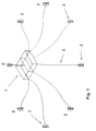
- Fig. 1 shows, as stated, a perspective diagram of a platform 1 which is anchored, via anchor lines 3, to anchors 2 in accordance with the present invention.
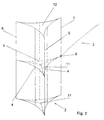
- the anchor 2 is, in the example shown here, triangular (star-shaped) with concave (curved) side surfaces 4, but with straight generants and corners 5, 6 and 7 which are aligned in the vertical direction of the anchor.
- An anchor which is designed for suction is fitted with a top plate 12, whereas an anchor which is lowered (knocked) into the soil in another way is appropriately open at both ends.
- Fig. 3 shows a horizontal section of the anchor shown in Fig. 2 with a force arrow "F" which indicates the tensile force and its direction for the anchor line.
- the side surfaces 4 meet at corners 5, 6 and 7, which are preferably without eccentricity (see, in particular, Fig. 4) so that no bending moments occur around the corners.
- the corners 5, 6 and 7 can be formed most easily by welding the side surfaces 4 directly to each other but should preferably, as shown in the figure, be formed by welding the side surfaces 4 to a hollow section in the form of a square section, tubular section or possibly plain bar.
- the corner 7, which also forms the fixing point for the anchor line 3, should be provided with a reinforced part (not shown in detail), preferably a thicker plate, in the area of the fixing eye 9 (see Fig. 2) for the line 3.
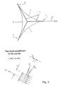
- Fig. 4 shows, in principle, how the anchor is subjected to load in the operating state.
- the tension in the front side surfaces 4, represented by “S” in Fig. 4 balances the compressive forces in the side surfaces while the pressure represented by “C” supports the compressive forces which act along the rear surface 4.
- the plates are preferably so soft that, if the pressure is anything other than that assumed, the corners will assume a different position until a new equilibrium is achieved.
- the pressure in the side surfaces is thus in equilibrium with the tension, the membrane stresses in the plates, without large bending stresses being created.
- the principle of membrane stresses occurring without bending stresses is due to the curved shape of the side surfaces and contributes to allowing the thickness of the material to be made very thin in comparison with a similar anchor with straight sides so that the weight of the anchor is reduced accordingly.
- the design of the present invention with curved side surfaces also contributes to better force transmission from the anchor line as the forces are mainly absorbed as tensile and compressive forces in the side surfaces (membrane stresses). With a bucket anchor, the force transmission from the anchor line will also result in large bending stresses.
- the size of a suction anchor designed for a floating platform in the North Sea, with curved sides in accordance with the present invention can be 10-15 metres in height (depth) and 8-10 metres for the width of the side surfaces.
- depth depth
- width of the side surfaces could be 4-6 metres.
- Fig. 5 shows an alternative design of an anchor in accordance with the present invention which is provided with four side surfaces.
- the present invention as it is described in the above and shown in the figures, is not restricted to anchors with three or four side surfaces, but can in reality also be used for anchors with any number of sides.
- An anchor in accordance with the present invention with three side surfaces as shown in Fig. 3 will, in an operational situation, i.e. when it has been submerged sufficiently in the bed, be "self-supporting" in the sense that it is not necessary to have any cross-stays or reinforcements in addition to that which is mentioned above concerning the fixing eye for the anchor line.
- a suction anchor and depending on the quality of the soil (bed)
- the stays Under normal operating conditions, after the anchor has been submerged in the bed, the stays will not, however, fulfil any function.
- the advantage of the shape of an anchor with four or more corners is that it allows for side surfaces with greater curvature, which increases the strength of the anchor in cases in which the anchor has to be pressed up again (suction anchor), for example in the event of incorrect positioning.
Landscapes
- Chemical & Material Sciences (AREA)
- Engineering & Computer Science (AREA)
- Combustion & Propulsion (AREA)
- Mechanical Engineering (AREA)
- Ocean & Marine Engineering (AREA)
- Piles And Underground Anchors (AREA)
- Revetment (AREA)
- Laying Of Electric Cables Or Lines Outside (AREA)
- Surgical Instruments (AREA)
- Valve Device For Special Equipments (AREA)
- Iron Core Of Rotating Electric Machines (AREA)
Claims (6)
- Anker für die Verankerung von schwimmenden Strukturen auf See, insbesondere von schwimmenden Plattformen für die Produktion von Öl und/oder Gas, Anker der einen Hohlkörper (2) aufweist, der so konzipiert ist, dass er durch Ansaugen oder durch irgendein anderes Hilfsmittel in dem Seebett untergetaucht werden kann,
dadurch gekennzeichnet, dass
der Körper ein konkave Seitenoberflächen aufweisendes Polygon ist. - Anker gemäss Anspruch 1
dadurch gekennzeichnet, dass
die Seiten des Ankers direkt an einer jeden Ecke durch Schweißen miteinander verbunden sind. - Anker gemäss Anspruch 1
dadurch gekennzeichnet, dass
die Seiten an einer jeden Ecke durch Schweißen via einen einfachen Stab oder ein Profil miteinander verbunden sind. - Anker gemäss Anspruch 3
dadurch gekennzeichnet, dass
das profil einen quadratischen oder röhrenförmigen Querschnitt aufweist. - Anker gemäss den Ansprüchen 1- 4,
dadurch gekennzeichnet, dass
der Anker ein Sauganker ist und dass das obere Ende des Ankers geschlossen ist. - Anker gemäss den Ansprüchen 1- 5,
dadurch gekennzeichnet, dass
der Körper mit Streben 11 versehen ist, die sich von einer jeden Ecke aus erstrecken und die in der zentralen Achse miteinander verbunden sind.
Applications Claiming Priority (3)
| Application Number | Priority Date | Filing Date | Title |
|---|---|---|---|
| NO964931 | 1996-11-20 | ||
| NO964931A NO304279B1 (no) | 1996-11-20 | 1996-11-20 | Anker |
| PCT/NO1997/000296 WO1998022334A1 (en) | 1996-11-20 | 1997-11-10 | Anchor |
Publications (2)
| Publication Number | Publication Date |
|---|---|
| EP0939723A1 EP0939723A1 (de) | 1999-09-08 |
| EP0939723B1 true EP0939723B1 (de) | 2002-02-06 |
Family
ID=19900082
Family Applications (1)
| Application Number | Title | Priority Date | Filing Date |
|---|---|---|---|
| EP97946169A Expired - Lifetime EP0939723B1 (de) | 1996-11-20 | 1997-11-10 | Anker |
Country Status (11)
| Country | Link |
|---|---|
| US (1) | US6202586B1 (de) |
| EP (1) | EP0939723B1 (de) |
| CN (1) | CN1086661C (de) |
| AU (1) | AU713561B2 (de) |
| BR (1) | BR9713117A (de) |
| CA (1) | CA2272300A1 (de) |
| DK (1) | DK0939723T3 (de) |
| ID (1) | ID22152A (de) |
| NO (1) | NO304279B1 (de) |
| RU (1) | RU2198814C2 (de) |
| WO (1) | WO1998022334A1 (de) |
Families Citing this family (1)
| Publication number | Priority date | Publication date | Assignee | Title |
|---|---|---|---|---|
| CN103299894B (zh) * | 2013-06-20 | 2014-09-17 | 连云港海之林复合材料有限公司 | 一种可调式环保型深海水产养殖专用撑杆及其制备方法 |
Family Cites Families (12)
| Publication number | Priority date | Publication date | Assignee | Title |
|---|---|---|---|---|
| US1305507A (en) * | 1919-06-03 | Liam fkoger | ||
| US2556279A (en) * | 1948-04-10 | 1951-06-12 | Edwin L Johnson | Anchor |
| US3431879A (en) * | 1967-08-11 | 1969-03-11 | Gulf Oil Corp | Method and apparatus for offshore anchoring |
| US3496900A (en) * | 1968-05-23 | 1970-02-24 | Texaco Inc | Method for installing a deep water anchor |
| US3823563A (en) * | 1972-09-05 | 1974-07-16 | Eng Technology Analysts Inc | Spud tank for offshore drilling unit |
| JPS5389191A (en) * | 1977-01-14 | 1978-08-05 | Mitsubishi Heavy Ind Ltd | Triangular sinker with pawl |
| US4155673A (en) | 1977-05-26 | 1979-05-22 | Mitsui Engineering & Shipbuilding Co. Ltd. | Floating structure |
| GB2201338B (en) * | 1984-01-30 | 1989-06-01 | Patrick Michael Kenny Sr | Embedment anchor |
| US4710061A (en) * | 1985-04-12 | 1987-12-01 | Atlantic Richfield Company | Offshore well apparatus and method |
| SU1556999A1 (ru) * | 1987-02-24 | 1990-04-15 | Московский Геологоразведочный Институт Им.Серго Орджоникидзе | Гидростатический корь |
| GB2227988B (en) * | 1988-09-07 | 1992-08-26 | John Bevan | An omnidirectional burial anchor |
| GB8905985D0 (en) | 1989-03-15 | 1989-04-26 | Roxbury Ltd | Improvements in or relating to piles |
-
1996
- 1996-11-20 NO NO964931A patent/NO304279B1/no not_active IP Right Cessation
-
1997
- 1997-11-10 RU RU99113021/28A patent/RU2198814C2/ru not_active IP Right Cessation
- 1997-11-10 WO PCT/NO1997/000296 patent/WO1998022334A1/en not_active Ceased
- 1997-11-10 EP EP97946169A patent/EP0939723B1/de not_active Expired - Lifetime
- 1997-11-10 ID IDW990378A patent/ID22152A/id unknown
- 1997-11-10 DK DK97946169T patent/DK0939723T3/da active
- 1997-11-10 CA CA002272300A patent/CA2272300A1/en not_active Abandoned
- 1997-11-10 AU AU51398/98A patent/AU713561B2/en not_active Ceased
- 1997-11-10 BR BR9713117-2A patent/BR9713117A/pt active Search and Examination
- 1997-11-10 US US09/308,561 patent/US6202586B1/en not_active Expired - Fee Related
- 1997-11-10 CN CN97199914A patent/CN1086661C/zh not_active Expired - Fee Related
Also Published As
| Publication number | Publication date |
|---|---|
| WO1998022334A1 (en) | 1998-05-28 |
| NO964931D0 (no) | 1996-11-20 |
| EP0939723A1 (de) | 1999-09-08 |
| NO964931L (no) | 1998-05-22 |
| CN1086661C (zh) | 2002-06-26 |
| RU2198814C2 (ru) | 2003-02-20 |
| DK0939723T3 (da) | 2002-05-21 |
| NO304279B1 (no) | 1998-11-23 |
| AU713561B2 (en) | 1999-12-02 |
| AU5139898A (en) | 1998-06-10 |
| CA2272300A1 (en) | 1998-05-28 |
| US6202586B1 (en) | 2001-03-20 |
| ID22152A (id) | 1999-09-09 |
| BR9713117A (pt) | 2000-04-11 |
| CN1237932A (zh) | 1999-12-08 |
Similar Documents
| Publication | Publication Date | Title |
|---|---|---|
| US4810135A (en) | Compliant offshore structure with fixed base | |
| KR102875546B1 (ko) | 해양 설비를 지지하기 위한 구조물 및 그 실행 방법(structure for supporting marine installations and procedure for the execution thereof) | |
| JP2020514181A (ja) | 浮体式海洋プラットフォーム | |
| EP0991566B1 (de) | Halbtauchende offshorestruktur mit grossem tiefgang | |
| US4696603A (en) | Compliant offshore platform | |
| KR900005914B1 (ko) | 가요성 해양 플랫포옴(Flexible Offshore Platform) | |
| WO2002031270A1 (en) | Heave suppressed offshore drilling and production platform | |
| EP0580714A1 (de) | Tiefseeplattform mit schwimmenden flexiblen pfeilern | |
| US4669917A (en) | Fixed marine steel structure and procedure for assembly of the structure | |
| CN1964886A (zh) | 浮动平台方法和装置 | |
| US4696604A (en) | Pile assembly for an offshore structure | |
| DK167541B1 (da) | Offshore platform med sammensatte ben | |
| US5713296A (en) | Lightweight concrete dock | |
| US4567843A (en) | Mooring system | |
| JPH11503383A (ja) | フローティング装置 | |
| EP0939723B1 (de) | Anker | |
| IE53081B1 (en) | An offshore mooring construction | |
| EP0830280B1 (de) | Aufzeichnungsschicht für verwendung mit farbstofftinten | |
| US4834014A (en) | Floating platform structure | |
| NL1023320C2 (nl) | De uitvinding heeft betrekking op een methode voor fabricage, installatie en verwijderen van een offshore platform. | |
| CN114084302B (zh) | 海上风机固定式基础、海上风机装置及海上风机整机的运输安装方法 | |
| US7422394B2 (en) | Tendon for tension leg platform | |
| EP0178311A1 (de) | Schwerkraftbühne für grosse wassertiefen, deren herstellungsverfahren und bühne | |
| MXPA99004564A (en) | Anchor | |
| JPS58166195A (ja) | タンクの頂部サポ−ト |
Legal Events
| Date | Code | Title | Description |
|---|---|---|---|
| PUAI | Public reference made under article 153(3) epc to a published international application that has entered the european phase |
Free format text: ORIGINAL CODE: 0009012 |
|
| 17P | Request for examination filed |
Effective date: 19990621 |
|
| AK | Designated contracting states |
Kind code of ref document: A1 Designated state(s): DK GB NL |
|
| GRAG | Despatch of communication of intention to grant |
Free format text: ORIGINAL CODE: EPIDOS AGRA |
|
| 17Q | First examination report despatched |
Effective date: 20010329 |
|
| GRAG | Despatch of communication of intention to grant |
Free format text: ORIGINAL CODE: EPIDOS AGRA |
|
| GRAH | Despatch of communication of intention to grant a patent |
Free format text: ORIGINAL CODE: EPIDOS IGRA |
|
| GRAH | Despatch of communication of intention to grant a patent |
Free format text: ORIGINAL CODE: EPIDOS IGRA |
|
| GRAA | (expected) grant |
Free format text: ORIGINAL CODE: 0009210 |
|
| REG | Reference to a national code |
Ref country code: GB Ref legal event code: IF02 |
|
| AK | Designated contracting states |
Kind code of ref document: B1 Designated state(s): DK GB NL |
|
| REG | Reference to a national code |
Ref country code: DK Ref legal event code: T3 |
|
| PG25 | Lapsed in a contracting state [announced via postgrant information from national office to epo] |
Ref country code: GB Free format text: LAPSE BECAUSE OF NON-PAYMENT OF DUE FEES Effective date: 20021110 |
|
| PLBE | No opposition filed within time limit |
Free format text: ORIGINAL CODE: 0009261 |
|
| STAA | Information on the status of an ep patent application or granted ep patent |
Free format text: STATUS: NO OPPOSITION FILED WITHIN TIME LIMIT |
|
| PG25 | Lapsed in a contracting state [announced via postgrant information from national office to epo] |
Ref country code: DK Free format text: LAPSE BECAUSE OF NON-PAYMENT OF DUE FEES Effective date: 20021231 |
|
| 26N | No opposition filed |
Effective date: 20021107 |
|
| PG25 | Lapsed in a contracting state [announced via postgrant information from national office to epo] |
Ref country code: NL Free format text: LAPSE BECAUSE OF NON-PAYMENT OF DUE FEES Effective date: 20030601 |
|
| GBPC | Gb: european patent ceased through non-payment of renewal fee | ||
| REG | Reference to a national code |
Ref country code: DK Ref legal event code: EBP |
|
| NLV4 | Nl: lapsed or anulled due to non-payment of the annual fee |
Effective date: 20030601 |