EP0939448A1 - Battery case and surface-treated steel sheet for battery case - Google Patents
Battery case and surface-treated steel sheet for battery case Download PDFInfo
- Publication number
- EP0939448A1 EP0939448A1 EP97918403A EP97918403A EP0939448A1 EP 0939448 A1 EP0939448 A1 EP 0939448A1 EP 97918403 A EP97918403 A EP 97918403A EP 97918403 A EP97918403 A EP 97918403A EP 0939448 A1 EP0939448 A1 EP 0939448A1
- Authority
- EP
- European Patent Office
- Prior art keywords
- nickel
- steel sheet
- container
- plating
- battery case
- Prior art date
- Legal status (The legal status is an assumption and is not a legal conclusion. Google has not performed a legal analysis and makes no representation as to the accuracy of the status listed.)
- Granted
Links
Classifications
-
- C—CHEMISTRY; METALLURGY
- C25—ELECTROLYTIC OR ELECTROPHORETIC PROCESSES; APPARATUS THEREFOR
- C25D—PROCESSES FOR THE ELECTROLYTIC OR ELECTROPHORETIC PRODUCTION OF COATINGS; ELECTROFORMING; APPARATUS THEREFOR
- C25D3/00—Electroplating: Baths therefor
- C25D3/02—Electroplating: Baths therefor from solutions
- C25D3/56—Electroplating: Baths therefor from solutions of alloys
- C25D3/562—Electroplating: Baths therefor from solutions of alloys containing more than 50% by weight of iron or nickel or cobalt
-
- H—ELECTRICITY
- H01—ELECTRIC ELEMENTS
- H01M—PROCESSES OR MEANS, e.g. BATTERIES, FOR THE DIRECT CONVERSION OF CHEMICAL ENERGY INTO ELECTRICAL ENERGY
- H01M50/00—Constructional details or processes of manufacture of the non-active parts of electrochemical cells other than fuel cells, e.g. hybrid cells
- H01M50/10—Primary casings; Jackets or wrappings
- H01M50/116—Primary casings; Jackets or wrappings characterised by the material
- H01M50/117—Inorganic material
- H01M50/119—Metals
-
- H—ELECTRICITY
- H01—ELECTRIC ELEMENTS
- H01M—PROCESSES OR MEANS, e.g. BATTERIES, FOR THE DIRECT CONVERSION OF CHEMICAL ENERGY INTO ELECTRICAL ENERGY
- H01M50/00—Constructional details or processes of manufacture of the non-active parts of electrochemical cells other than fuel cells, e.g. hybrid cells
- H01M50/10—Primary casings; Jackets or wrappings
- H01M50/116—Primary casings; Jackets or wrappings characterised by the material
- H01M50/124—Primary casings; Jackets or wrappings characterised by the material having a layered structure
- H01M50/1243—Primary casings; Jackets or wrappings characterised by the material having a layered structure characterised by the internal coating on the casing
-
- H—ELECTRICITY
- H01—ELECTRIC ELEMENTS
- H01M—PROCESSES OR MEANS, e.g. BATTERIES, FOR THE DIRECT CONVERSION OF CHEMICAL ENERGY INTO ELECTRICAL ENERGY
- H01M50/00—Constructional details or processes of manufacture of the non-active parts of electrochemical cells other than fuel cells, e.g. hybrid cells
- H01M50/10—Primary casings; Jackets or wrappings
- H01M50/116—Primary casings; Jackets or wrappings characterised by the material
- H01M50/124—Primary casings; Jackets or wrappings characterised by the material having a layered structure
- H01M50/126—Primary casings; Jackets or wrappings characterised by the material having a layered structure comprising three or more layers
- H01M50/128—Primary casings; Jackets or wrappings characterised by the material having a layered structure comprising three or more layers with two or more layers of only inorganic material
-
- H—ELECTRICITY
- H01—ELECTRIC ELEMENTS
- H01M—PROCESSES OR MEANS, e.g. BATTERIES, FOR THE DIRECT CONVERSION OF CHEMICAL ENERGY INTO ELECTRICAL ENERGY
- H01M50/00—Constructional details or processes of manufacture of the non-active parts of electrochemical cells other than fuel cells, e.g. hybrid cells
- H01M50/10—Primary casings; Jackets or wrappings
- H01M50/131—Primary casings; Jackets or wrappings characterised by physical properties, e.g. gas permeability, size or heat resistance
- H01M50/133—Thickness
-
- H—ELECTRICITY
- H01—ELECTRIC ELEMENTS
- H01M—PROCESSES OR MEANS, e.g. BATTERIES, FOR THE DIRECT CONVERSION OF CHEMICAL ENERGY INTO ELECTRICAL ENERGY
- H01M50/00—Constructional details or processes of manufacture of the non-active parts of electrochemical cells other than fuel cells, e.g. hybrid cells
- H01M50/10—Primary casings; Jackets or wrappings
- H01M50/131—Primary casings; Jackets or wrappings characterised by physical properties, e.g. gas permeability, size or heat resistance
- H01M50/134—Hardness
-
- H—ELECTRICITY
- H01—ELECTRIC ELEMENTS
- H01M—PROCESSES OR MEANS, e.g. BATTERIES, FOR THE DIRECT CONVERSION OF CHEMICAL ENERGY INTO ELECTRICAL ENERGY
- H01M50/00—Constructional details or processes of manufacture of the non-active parts of electrochemical cells other than fuel cells, e.g. hybrid cells
- H01M50/50—Current conducting connections for cells or batteries
- H01M50/543—Terminals
- H01M50/552—Terminals characterised by their shape
- H01M50/559—Terminals adapted for cells having curved cross-section, e.g. round, elliptic or button cells
- H01M50/56—Cup shaped terminals
-
- H—ELECTRICITY
- H01—ELECTRIC ELEMENTS
- H01M—PROCESSES OR MEANS, e.g. BATTERIES, FOR THE DIRECT CONVERSION OF CHEMICAL ENERGY INTO ELECTRICAL ENERGY
- H01M10/00—Secondary cells; Manufacture thereof
- H01M10/24—Alkaline accumulators
- H01M10/30—Nickel accumulators
-
- H—ELECTRICITY
- H01—ELECTRIC ELEMENTS
- H01M—PROCESSES OR MEANS, e.g. BATTERIES, FOR THE DIRECT CONVERSION OF CHEMICAL ENERGY INTO ELECTRICAL ENERGY
- H01M2300/00—Electrolytes
- H01M2300/0002—Aqueous electrolytes
- H01M2300/0014—Alkaline electrolytes
-
- H—ELECTRICITY
- H01—ELECTRIC ELEMENTS
- H01M—PROCESSES OR MEANS, e.g. BATTERIES, FOR THE DIRECT CONVERSION OF CHEMICAL ENERGY INTO ELECTRICAL ENERGY
- H01M50/00—Constructional details or processes of manufacture of the non-active parts of electrochemical cells other than fuel cells, e.g. hybrid cells
- H01M50/10—Primary casings; Jackets or wrappings
- H01M50/116—Primary casings; Jackets or wrappings characterised by the material
- H01M50/124—Primary casings; Jackets or wrappings characterised by the material having a layered structure
-
- Y—GENERAL TAGGING OF NEW TECHNOLOGICAL DEVELOPMENTS; GENERAL TAGGING OF CROSS-SECTIONAL TECHNOLOGIES SPANNING OVER SEVERAL SECTIONS OF THE IPC; TECHNICAL SUBJECTS COVERED BY FORMER USPC CROSS-REFERENCE ART COLLECTIONS [XRACs] AND DIGESTS
- Y02—TECHNOLOGIES OR APPLICATIONS FOR MITIGATION OR ADAPTATION AGAINST CLIMATE CHANGE
- Y02E—REDUCTION OF GREENHOUSE GAS [GHG] EMISSIONS, RELATED TO ENERGY GENERATION, TRANSMISSION OR DISTRIBUTION
- Y02E60/00—Enabling technologies; Technologies with a potential or indirect contribution to GHG emissions mitigation
- Y02E60/10—Energy storage using batteries
-
- Y—GENERAL TAGGING OF NEW TECHNOLOGICAL DEVELOPMENTS; GENERAL TAGGING OF CROSS-SECTIONAL TECHNOLOGIES SPANNING OVER SEVERAL SECTIONS OF THE IPC; TECHNICAL SUBJECTS COVERED BY FORMER USPC CROSS-REFERENCE ART COLLECTIONS [XRACs] AND DIGESTS
- Y10—TECHNICAL SUBJECTS COVERED BY FORMER USPC
- Y10T—TECHNICAL SUBJECTS COVERED BY FORMER US CLASSIFICATION
- Y10T428/00—Stock material or miscellaneous articles
- Y10T428/12—All metal or with adjacent metals
- Y10T428/12493—Composite; i.e., plural, adjacent, spatially distinct metal components [e.g., layers, joint, etc.]
- Y10T428/12771—Transition metal-base component
- Y10T428/12861—Group VIII or IB metal-base component
- Y10T428/12937—Co- or Ni-base component next to Fe-base component
Definitions
- the present invention concerns a container where alkaline solution is packed.
- a method of barrel plating after press forming cold-rolled steel strip into a battery container or a method of press forming nickel-plated steel strip into a battery container have been adopted for manufacturing a battery container for such as alkali-manganese batteries and nickel cadmium batteries in which strong alkaline solution is packed.
- nickel plating is used for batteries such as alkali manganese batteries and nickel cadmium batteries.
- Nickel having excellent corrosion resistance to alkali is suitable for these batteries whose electrolyte is chiefly strong alkaline potassium hydroxide.
- nickel is suitable for batteries since nickel has steady contact resistance when the battery is connected with an external terminal.
- nickel has excellent spot welding properties in case where each component is spot welded when assembled into a battery in the battery manufacturing process.
- the lower the contact resistance between the inside of the positive electrode container and the positive electrode mix of the alkali manganese battery consisting of manganese dioxide as a positive electrode active material, graphite as a conductor, and potassium hydroxide as electrolyte
- the positive electrode mix and the positive electrode container are in contact, and the positive electrode container serves as not only a container of the battery but also as a conductor which transfers electrons.
- the contact resistance between the positive electrode mix and the inner surface of the positive electrode container is great, the internal resistance of the battery rises. It causes decrease in the operation voltage and in the electrical discharge duration, obstructing the battery performance. So, it is desirable to decrease the contact resistance between the positive electrode mix and the inner surface of the positive electrode container. Therefore, roughing the surface inner surface the positive electrode container, making a ditch on the positive electrode container in the vertical direction, and applying conductive coating or a conducting material made by adding binder to graphite are proposed to decrease the contact resistance between the positive electrode mix and the inner surface of the positive electrode container.
- DI drawing and ironing
- DTR drawing thin and redraw
- the DI forming method and the DTR forming method are effective for increasing battery capacity as mentioned above, there is a disadvantage when they are used for continuous forming because the deformation resistance of the material in those methods is greater than in the conventional multi step deep-drawing forming method.
- the powdering quality prowdery dropout of the plating layer
- the powder adheres to the die and the punch in the ironing process causing a defect in the container side wall.
- the similar phenomenon happens in the deep-drawing forming, the above-mentioned defect is more remarkable in the DI forming method and the DTR forming method because the container wall has small surface roughness, which produced more lustrous appearance.
- powdering quality is more critical in the DI forming method and the DTR forming method. Also, because the contact pressure of the material and the tool is greater in the DI forming method and the DTR forming method than that in the drawing method, favorable lubrication is requested for tool life. Therefore, materials which have a favorable powdering quality and retention of the press lubricant are requested.
- one of the ways to improve the retention of the lubricant is to cause cracks in the plating layer at the press-forming step and to hold the lubricant in the part where cracks are caused.
- gloss nickel plating producing a hard plating layer is generally brought to mind.
- the gloss nickel plating produces a hard gloss plating layer, it is brittle and it has inferior powdering quality at the press-forming.
- the inventor of the present invention examined various materials for a battery container having excellent formability in the DI forming method and the DTR forming method from such viewpoints, and found that nickel-cobalt alloy plating is suitable.
- the present invention is based on such findings and it is aimed at a battery container having high quality and excellent continuous formability and a surface treated steel sheet which is suitable for producing the said battery container.
- Another objective of the present invention is to improve the removability of container (strippability) after the DI forming and the DTR forming. This is taken into consideration since the difficulty of stripping the container from the punch (strippability) in the final pressing process is critical in the container manufacturing in addition to the above-mentioned powdering quality.
- stripping where the container is pulled out from the punch hitching fingernails on the edge of the container, there was a problem that an inferior stripping caused breaking and split at the open edge portion of the container more frequently, which deteriorated the productivity.
- the battery container as claimed in Claim 1 which achieves the above mentioned purpose is obtained by forming a surface treated steel sheet, of which inside and outside are plated with nickel-cobalt alloy, using DI forming method or DTR forming method.
- the battery container as claimed in Claim 2 is assumed to be the battery container as claimed in Claim 1 in which cobalt content of the above-mentioned nickel-cobalt alloy plating is from 0.5 to 10 percent by weight.
- the battery container claimed in Claim 3 is assumed to be the battery container as claimed in Claim 1 in which the thickness of the above-mentioned nickel cobalt-alloy plating is from 0.5 to 3 ⁇ m for the inside of the container and from 1.0 to 4 ⁇ m for the outside of the container.
- the battery container claimed in Claim 4 is obtained by forming a surface treated steel sheet, of which inside and outside are plated with nickel-iron alloy, using DI forming method or DTR forming method.
- the battery container as claimed in Claim 5 is assumed to be the battery container as claimed in Claim 4 in which the iron content of the above-mentioned nickel-iron alloy plating is from 0.5 to 5 percent by weight.
- the battery container as claimed in Claim 6 is assumed to be the battery container as claimed in Claim 5 in which the thickness of the above-mentioned nickel-iron alloy plating is from 0.5 to 3 ⁇ m for the inside of the container and from 1.0 to 4 ⁇ m for the outside of the container.
- the surface treated steel sheet as claimed in Claim 7 is made by plating inside and outside a steel sheet with nickel-cobalt alloy.
- the surface treated steel sheet as claimed in Claim 8 is assumed to be the surface treated steel sheet as claimed in Claim 7 in which the cobalt content of the above-mentioned nickel-cobalt alloy plating is from 0.5 to 10 percent by weight.
- the surface treated steel sheet as claimed in Claim 9 is made by plating inside and outside a steel sheet with nickel-iron alloy.
- the surface treated steel sheet as claimed in Claim 10 is assumed to be the surface treated steel sheet as claimed in Claim 9 in which iron content of the above-mentioned nickel-iron alloy plating is from 0.5 to 5 percent by weight.
- the surface hardness of the plating by the nickel sulfamate bath rises to about 300 to 320 (Vickers hardness) when cobalt is added by 1g/ l (cobalt content 5%), while it is about 220 to 230 (Vickers hardness ) when cobalt is not added.
- the hardness of the plating layer of the nickel-iron alloy plating reaches about 500 (Vickers hardness) when containing iron by 3 to 5% in the nickel plating layer.
- the surface treated steel sheet having hardened plating layer was manufactured, and then this surface treated steel sheet was formed into a battery container (alkali manganese battery LR6 type) using the DI forming method and the DTR forming method, etc. And when the side wall inside and outside of the battery container was observed with a microscope, a fine surface roughening was observed.
- the lubricant inside and outside of the manufactured battery container was removed with an organic solvent and then the powder dropped out from the plating layer was adhered to the adhesive tape and the amount was observed with the magnifying glass (magnification 25 times). As a result, remarkable decrease in the powdering quality was observed.
- the punching load is small because the lubricant enters the above-mentioned finely rugged surface of the surface treated steel sheet in the cupping process and the friction resistance decreases in the subsequent ironing process of the DI forming and the stretching process of the DTR forming due to the favorable retention of the lubricant between the materials and the die or the punch. It is greatly advantageous that the defects of the die and the punch due to metal-to-metal contact decrease because of the lowered punching load, resulting in longer die life and improved continuous productivity of the battery container. And favorable retention of the lubricant is also advantageous for the removability (strippability) of the battery container which is an important factor in the DI formability and the DTR formability.
- the present invention is not only applied in the DI forming method and the DTR forming method as a means to thin the wall of the battery container, but also favorably applicable in the conventional multi step deep-drawing method because it improves the powdering quality and decreases defects.
- the adhesion of the positive electrode mix to the inside of the container, and the adhesion of the graphite coating coated inside the battery container to the positive electrode mix after formed into the battery container are improved by the existence of the above-mentioned finely rugged surface.
- the use of the plated steel sheet of the present invention compensates the drawbacks that the surface roughness inside the container formed using the DI forming method and the DTR forming method is small and that the adhesion of it to the positive electrode mix or the graphite coating is inferior.
- the nickel-based alloy plating containing cobalt and iron of the present invention are involved in the iron-group which has excellent resistance to alkali corrosion and dissolution, it is a suitable material for the batteries such as the alkali manganese batteries, the nickel cadmium batteries, and the nickel hydrogen batteries of which electrolyte is high concentration alkaline solution.
- the suitable cobalt content of the nickel-cobalt alloy plating is from 0.5% to 10%.
- the cobalt content is less than 0.5%, it is not effective for hardening the cobalt plating layer.
- the cobalt content is exceeding 10%, it is uneconomical because the hardening effect on the surface treated steel sheet is saturated and also because cobalt is expensive precious metal.
- the suitable iron content is from 0.5% to 5%.
- the iron content is less than 0.5%, hardening effect can not be obtained.
- the iron content is exceeding 5%, the hardening effect is saturated, and it also causes difficulty to control the bath when the iron content increases any further.
- the preferable range for the inside of the container is from 0.5 to 3.0 ⁇ m both for the nickel-cobalt alloy plating and the nickel-iron alloy plating.
- the preferable range for the outside of it is from 1.0 to 4.0 ⁇ m.
- the plating thickness of inside the container is less than 0.5 ⁇ m, the exposure of the steel substrate is increased and the corrosion resistance is inferior in the container of batteries such as alkali manganese battery, causing deterioration in the battery performance due to dissolving out of the ferrous ion into the electrolyte.
- the plating thickness outside the container is less than 1.0 ⁇ m, rust might be generated on the battery container during press forming process and the battery manufacturing process and while preserving it for a long period of time since it does not have enough corrosion resistance.
- the upper limits of the plating thicknesses inside and outside of the container are 0.3 ⁇ m and 0.4 ⁇ m, respectively, because the effect is saturated when the plating thickness exceeds these values and also it is uneconomical to make them any thicker.
- a low carbon aluminum killed steel is suitably used a base material of a surface treated steel sheet.
- cold-rolled steel strip prepared from non-aging hyper low carbon steel (carbon content is less than 0.01%) with niobium and / or titanium added is also used.
- the steel strip subjected Electro-cleaning, annealing, and temper rolling after cold-rolling using a conventional method is used as a substrate for plating. After that a surface treated steel sheet is manufactured by plating the steel substrate with nickel-cobalt alloy or nickel-iron alloy.
- sulfamate bath is suitable since it is comparatively easy to be controlled. Since either ratio of cobalt or iron to nickel deposited into plating layer is several times greater than that of concentration in either plating bath, it is possible to use nickel anode for anode and to supply cobalt and ferrous ions in the form of sulfamate or sulfate.
- Low carbon aluminum killed steel sheets subjected to cold-rolling, annealing, and temper rolling having the thickness of 0.25 mm and 0.4 mm were used as the substrates for plating.
- the chemical compositions of both steel substrates were as follows. C:0.04% (% means percent by weight, same for the following), Mn:0.22%, Si:0.01%, P:0.012%, S:0.006%, Al:0.048%, N:0.0025%.
- the above-mentioned steel substrates were plated with nickel-cobalt alloy and nickel-iron alloy on the following conditions and made into surface treated steel sheets.
- the amount of iron content and the thickness of the plating film were varied by changing the amount of adding iron sulfamate and the electrolysis duration on the above-mentioned conditions. After the above-mentioned nickel-cobalt alloy plating and the nickel-iron alloy plating were done, the plating layer was dissolved to 3 % nitric acid and the plating thickness and the alloy composition of the plating film were analyzed with ICP (inductively coupled plasma atomic emission spectrochemical analysis) method.
- ICP inductively coupled plasma atomic emission spectrochemical analysis
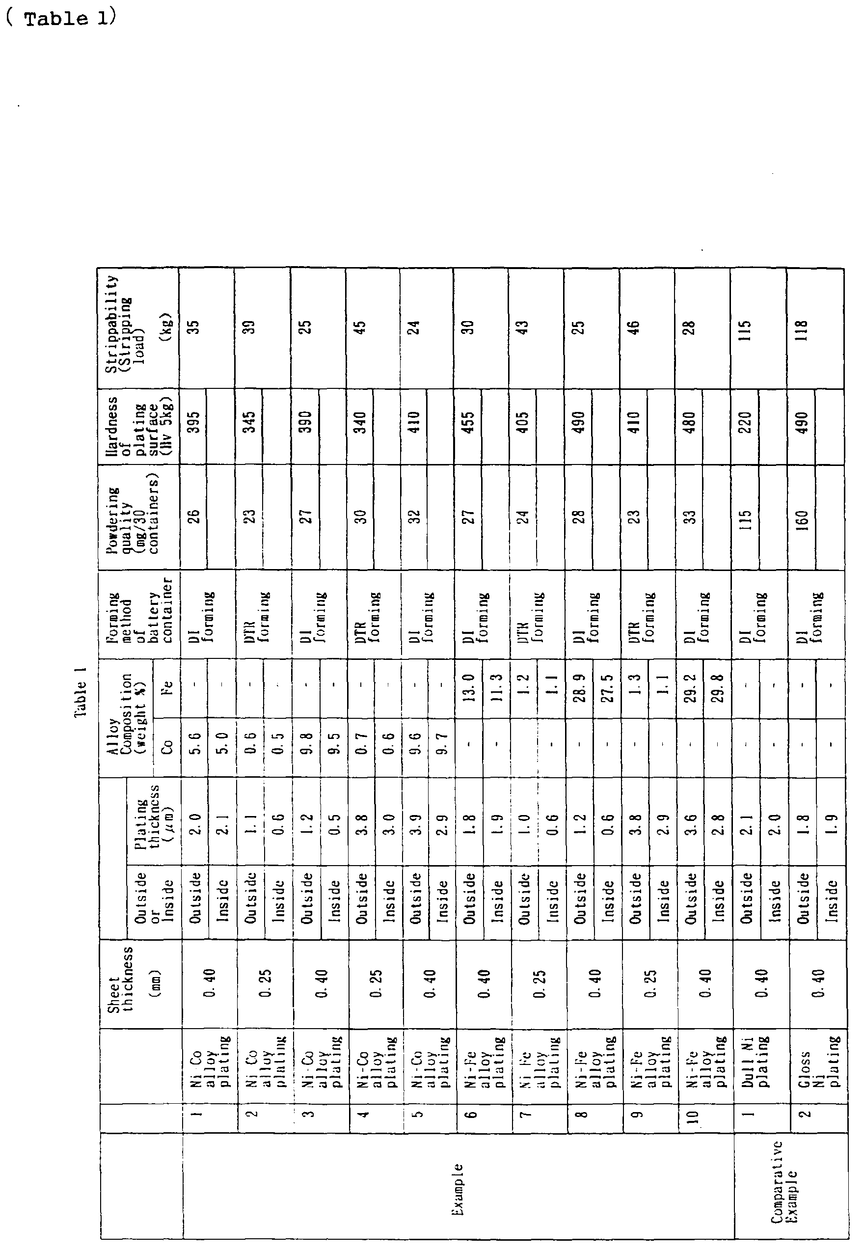
- the plating thickness ( ⁇ m) was determined by dividing the dissolved amount value of each element with the value of the plated area and considering the specific gravity of each element. Table 1 shows those results.
- the battery container formed by the DI forming method As for the battery container formed by the DI forming method, the above-mentioned plated steel sheet having the thickness of 0.4 mm was punched out into a blank 41 mm in diameter, drawn into a cup 20.5 mm in diameter, and then formed into 13.8 mm in outside diameter, 0.20 mm in container wall thickness and 56 mm in height by redrawing and two-step ironing using DI forming machine. Finally, the upper part was trimmed off to shape a LR6 type battery container 49.3 mm in height.
- the plated steel sheet 0.25 mm in sheet thickness was punched out into a blank 58 mm in diameter, and then shaped into a LR type battery container 13.8 mm in outside diameter, 0.20 mm in container wall thickness and 49.3 mm in height by several times of drawing and redrawing.
- the powdering quality was evaluated by the decrease in weight after forming in the manufacturing process of the above-mentioned battery container.
- the process was comprising blanking ⁇ cupping ⁇ degreasing ⁇ weight measurement (1) ⁇ forming ⁇ degreasing ⁇ weight measurement (2).
- Degreasing was conducted by alkali dipping degreasing followed by ultrasonic cleaning in acetone.
- Table 1 shows the result. As is apparent in Table 1, while in the comparative example of 1 to 6, a large number of powders dropout from the containers (from 74 to 160 mg/30 containers), in this present inventions example of 1 to 10, a small number of powders dropout (from 23 to 33/(30 containers)). This shows that the battery container of the present invention is excellent in powdering.
- the surface hardness of the plating layer of the samples obtained in the examples and the comparative examples were measured using the Vickers hardness testing machine (load: 5g). Table 1 shows the result.
- Strippability in the DI forming was measured as follows.
- the stripping load required when pulling out the container from the punch by returning the punch after ironing process was measured with a load cell installed in the punch. As shown in Table 1, the stripping load of each example of this invention is less than 50 kg, while those of comparative examples exceed 100 kg. This shows that the stripability of the battery container of the present invention is excellent.
- the battery container as claimed in Claim 1 is obtained by forming surface treated steel sheet, which is made by plating inside and outside the substrate of steel sheet with nickel-cobalt alloy, using DI forming method or DTR forming method. Since the powdering is remarkably decreased in the nickel-cobalt alloy plating, the punching load can be lowered in the cupping process. Therefore, generation of defects of the die and the punch due to metal-to metal contact is reduced, resulting in longer die life and improved continuous productivity of the battery container. Moreover, favorable retention of the lubricant improves the removability of the battery container (strippability) which is an important factor in the DI formability and the DTR formability.
- the cobalt content contained in the nickel-cobalt alloy plating of the battery container as claimed in Claim 2 is from 0.5 to 10 percent by weight. This enables to fully harden the nickel-cobalt alloy plating inside and outside of the battery container while considering the economy.
- the thickness of the nickel-cobalt alloy plating of the battery container as claimed in Claim 3 is from 0.5 to 3 ⁇ m for the inside of it and from 1.0 to 4 ⁇ m for the outside of it. So, deterioration in the battery performance due to the ferrous ion solve-out into the electrolyte resulted from corrosion at the exposed portion of the steel substrate can be surely prevented. At the same time, it enables to smoothly conduct the press working of the battery container and to surely prevent the rust generation while preserving the container for a long period of time.
- the battery container as claimed in Claim 4 is obtained by forming the surface treated steel sheet, which is prepared by plating inside and outside of the steel substrate with nickel-iron alloy, using the DI forming method or the DTR forming method. Since powdering can be remarkably decreased in the nickel-iron alloy plating as well as in the nickel-cobalt alloy plating, the punch load can be lowered in the cupping process. This enables to reduce the generation of defects of the die and the punch due to metal-to metal contact, resulting in longer die life and improved continuous productivity of the battery container.
- the iron content of the nickel-iron alloy plating of the battery container as claimed in Claim 5 is from 0.5 to 5 percent by weight. This enables to fully harden the nickel-iron alloy plating inside and outside of the battery container as well as to control the bath steadily while considering the economy.
- the thickness of the nickel-iron alloy plating of the battery container as claimed in Claim 6 is from 0.5 to 3 ⁇ m for the inside of the container. On the other hand, it is from 1.0 to 4 ⁇ m for the outside of it.
- the surface treated steel sheet as claimed in Claim 7 is a suitable material for the battery container as claimed in Claim 1, since the nickel-cobalt alloy plating is given to the inside and outside of the substrate.
- the cobalt content of the nickel-cobalt alloy plating of the surface treated steel sheet as claimed in Claim 8 is from 0.5 to 10 percent by weight. This surface treated steel sheet enables to fully harden the nickel-cobalt alloy plating inside and outside of the battery container when the it is manufactured into a battery container while considering the economy.
- the surface treated steel sheet as claimed in Claim 9 is a suitable material for the battery container as claimed in Claim 4 since the nickel-iron alloy plating is given to the inside and outside of the steel substrate.
- the iron content of the nickel-iron alloy plating of the surface treated steel sheet as claimed in Claim 10 is from 0.5 to 5 percent by weight.
- This surface treated steel sheet enables to fully harden the nickel-iron alloy plating inside and outside of the battery container as well as to control the bath steadily when it is manufactured into a battery container while considering the economy.
Landscapes
- Chemical & Material Sciences (AREA)
- Chemical Kinetics & Catalysis (AREA)
- Electrochemistry (AREA)
- General Chemical & Material Sciences (AREA)
- Inorganic Chemistry (AREA)
- Engineering & Computer Science (AREA)
- Materials Engineering (AREA)
- Metallurgy (AREA)
- Organic Chemistry (AREA)
- Sealing Battery Cases Or Jackets (AREA)
- Electroplating Methods And Accessories (AREA)
Abstract
Description
| nickel sulfamate | Ni(NH2SO3)·4H2O | 600 g/l |
| nickel chloride | NiCl2·6H2O | 10 g/ l |
| cobalt sulfate | CoSO4·6H2O | 5-20g/ l |
| boric acid | H3BO3 | 40 g/ l |
| citric acid | 0.6 g/l | |
| saccharin | 0.5 g/l |
| nickel sulfamate | Ni(NH2SO3)·4H2O | 450 g/l |
| iron sulfamate | Fe(NH2SO3)·5H2O | 0-7 g/l |
| boric acid | H3BO3 | 45 g/ l |
| citric acid | 0.6 g/l | |
| saccharin | 0.5 g/l |
Claims (10)
- A battery container obtained by forming a surface treated steel sheet of which inside and outside are plated with nickel-cobalt alloy using DI forming method or DTR forming method.
- The battery container as claimed in Claim 1, in which the cobalt content of the said nickel-cobalt alloy plating is from 0.5 to 10 percent by weight.
- The battery container as claimed in Claim 1, in which the thickness of the said nickel-cobalt alloy plating is from 0.5 to 3 µm for the inside of the container and from 1.0 to 4 µm for the outside of the container.
- The battery container obtained by forming a surface treated steel sheet of which inside and outside are plated with nickel-iron alloy, using DI forming method or DTR forming method.
- The battery container as claimed in Claim 4, in which the iron content of the said nickel-iron alloy plating is from 0.5 to 5 percent by weight.
- The battery container as claimed in Claim 4, in which the thickness of the said nickel-iron alloy plating is from 0.5 to 3 µm for the inside surface of the container and from 1.0 to 4 µm for the outside of the container.
- A surface treated steel sheet for battery container made by plating inside and outside a steel sheet with nickel-cobalt alloy.
- The surface treated steel board as claimed in Claim 7, in which the cobalt content of the said nickel-cobalt alloy plating is from 0.5 to 10 percent by weight.
- A surface treated steel sheet for battery container made by plating inside and outside a steel sheet with nickel-iron alloy.
- The surface treated steel board as claimed in Claim 9, in which the iron content of the said nickel-iron alloy plating is from 0.5 to 5 percent by weight.
Priority Applications (1)
| Application Number | Priority Date | Filing Date | Title |
|---|---|---|---|
| EP01112900A EP1191615B1 (en) | 1996-05-09 | 1997-05-09 | A method for manufacturing a surface treated steel sheet to be formed into a battery container |
Applications Claiming Priority (3)
| Application Number | Priority Date | Filing Date | Title |
|---|---|---|---|
| JP13775096 | 1996-05-09 | ||
| JP13775096 | 1996-05-09 | ||
| PCT/JP1997/001576 WO1997042667A1 (en) | 1996-05-09 | 1997-05-09 | Battery case and surface-treated steel sheet for battery case |
Related Child Applications (1)
| Application Number | Title | Priority Date | Filing Date |
|---|---|---|---|
| EP01112900A Division EP1191615B1 (en) | 1996-05-09 | 1997-05-09 | A method for manufacturing a surface treated steel sheet to be formed into a battery container |
Publications (3)
| Publication Number | Publication Date |
|---|---|
| EP0939448A1 true EP0939448A1 (en) | 1999-09-01 |
| EP0939448A4 EP0939448A4 (en) | 1999-09-01 |
| EP0939448B1 EP0939448B1 (en) | 2003-03-19 |
Family
ID=15205967
Family Applications (2)
| Application Number | Title | Priority Date | Filing Date |
|---|---|---|---|
| EP01112900A Expired - Lifetime EP1191615B1 (en) | 1996-05-09 | 1997-05-09 | A method for manufacturing a surface treated steel sheet to be formed into a battery container |
| EP97918403A Expired - Lifetime EP0939448B1 (en) | 1996-05-09 | 1997-05-09 | Battery case and surface-treated steel sheet for battery case |
Family Applications Before (1)
| Application Number | Title | Priority Date | Filing Date |
|---|---|---|---|
| EP01112900A Expired - Lifetime EP1191615B1 (en) | 1996-05-09 | 1997-05-09 | A method for manufacturing a surface treated steel sheet to be formed into a battery container |
Country Status (9)
| Country | Link |
|---|---|
| US (3) | US6087040A (en) |
| EP (2) | EP1191615B1 (en) |
| JP (1) | JP3429319B2 (en) |
| KR (1) | KR100436326B1 (en) |
| CN (1) | CN1198342C (en) |
| AU (1) | AU2652197A (en) |
| DE (2) | DE69720028T2 (en) |
| TW (1) | TW338071B (en) |
| WO (1) | WO1997042667A1 (en) |
Cited By (1)
| Publication number | Priority date | Publication date | Assignee | Title |
|---|---|---|---|---|
| US6979515B2 (en) | 2000-08-04 | 2005-12-27 | Toyo Kohan Co., Ltd. | Surface-treated steel plate for battery case and battery case |
Families Citing this family (25)
| Publication number | Priority date | Publication date | Assignee | Title |
|---|---|---|---|---|
| CN1127158C (en) * | 1996-09-03 | 2003-11-05 | 东洋钢钣株式会社 | Surface-treated steel sheet for battery case, battery case, and battery using same |
| JP3595347B2 (en) * | 1997-07-08 | 2004-12-02 | 東洋鋼鈑株式会社 | Surface-treated steel sheet for battery case, battery case, and battery using the same |
| JP3604879B2 (en) * | 1997-08-05 | 2004-12-22 | 松下電器産業株式会社 | Battery manufacturing method |
| DE19852202C2 (en) * | 1998-11-12 | 2002-01-24 | Hille & Mueller Gmbh & Co | Battery case made from formed, cold-rolled sheet metal and method for producing battery cases |
| AU3841000A (en) * | 1999-04-22 | 2000-11-10 | Toyo Kohan Co. Ltd. | Battery case and surface treated steel sheet for battery case |
| WO2000065672A1 (en) * | 1999-04-23 | 2000-11-02 | Toyo Kohan Co., Ltd. | Battery case and surface treated steel sheet for battery case |
| DE19949549A1 (en) * | 1999-10-14 | 2001-04-26 | Hille & Mueller Gmbh & Co | Electrolytically coated cold strip, preferably for use in the production of battery sleeves and processes for coating the same |
| WO2001084647A1 (en) * | 2000-04-28 | 2001-11-08 | Matsushita Electric Industrial Co., Ltd. | Cell tube and method of manufacturing the cell tube |
| JP4750950B2 (en) * | 2001-01-19 | 2011-08-17 | 新日本製鐵株式会社 | Ni-plated steel plate for alkaline manganese battery positive electrode can |
| US6730433B2 (en) * | 2002-01-16 | 2004-05-04 | The Gillette Company | Thin-wall anode can |
| US7507297B2 (en) | 2002-05-20 | 2009-03-24 | Panasonic Corporation | Cleaning method and cleaning apparatus |
| US20060159989A1 (en) * | 2005-01-19 | 2006-07-20 | Truelove & Maclean, Inc. | System and process for forming battery cans |
| JP3742422B1 (en) * | 2005-03-17 | 2006-02-01 | 日立マクセル株式会社 | Flat battery |
| US8158280B2 (en) * | 2006-05-24 | 2012-04-17 | Eveready Battery Company, Inc. | Battery container having cruciform vent and cover |
| US8304108B2 (en) * | 2009-07-17 | 2012-11-06 | Tesla Motors, Inc. | Method and apparatus for maintaining cell wall integrity using a high yield strength outer sleeve |
| JP5593167B2 (en) * | 2010-08-26 | 2014-09-17 | Fdkエナジー株式会社 | Alkaline battery |
| CN102117896B (en) * | 2011-01-28 | 2012-12-05 | 福建南平南孚电池有限公司 | Line rolling method of cylindrical battery |
| WO2012147843A1 (en) * | 2011-04-28 | 2012-11-01 | 東洋鋼鈑株式会社 | Surface-treated steel sheet for battery cases, battery case, and battery |
| JP6117099B2 (en) * | 2011-07-07 | 2017-04-19 | 東洋鋼鈑株式会社 | Surface-treated steel sheet for battery container and manufacturing method thereof, battery container and battery |
| WO2014061352A1 (en) | 2012-10-15 | 2014-04-24 | 東洋鋼鈑株式会社 | Method for producing metal plate having alloy plating layer |
| JP6292789B2 (en) | 2013-07-31 | 2018-03-14 | 東洋鋼鈑株式会社 | Surface-treated steel sheet for battery container, battery container and battery |
| WO2017153254A1 (en) * | 2016-03-07 | 2017-09-14 | Tata Steel Uk Limited | Method for manufacturing a steel sheet for a battery case and battery case made according the method |
| CN106367789B (en) * | 2016-11-04 | 2019-08-09 | 宁波堇山新材料有限公司 | Battery steel strip, battery steel case using the steel strip, and preparation method of the steel case |
| CN113748225B (en) * | 2019-04-27 | 2024-04-30 | 东洋钢钣株式会社 | Surface treated steel sheet and method for producing the same |
| CN110484945B (en) * | 2019-09-03 | 2021-06-15 | 福建南平南孚电池有限公司 | Electroplating solution and method for electroplating shell of battery by using same |
Family Cites Families (27)
| Publication number | Priority date | Publication date | Assignee | Title |
|---|---|---|---|---|
| US3607439A (en) * | 1969-07-02 | 1971-09-21 | Olin Mathieson | Minature battery or power cell containers |
| JPS5347939A (en) * | 1976-10-13 | 1978-04-28 | Fuji Electrochemical Co Ltd | Electric cell |
| JPS5359828A (en) * | 1976-10-21 | 1978-05-30 | Tokyo Shibaura Electric Co | Battery |
| CH626750A5 (en) * | 1977-03-31 | 1981-11-30 | Leclanche Sa | Alkaline button cell and method for manufacturing it |
| EP0031580B1 (en) * | 1979-12-29 | 1985-11-21 | Ebara Corporation | Coating metal for preventing the crevice corrosion of austenitic stainless steel |
| JPS6039455B2 (en) * | 1980-10-15 | 1985-09-06 | 日立造船株式会社 | Mold for continuous casting equipment |
| JPS6017854A (en) * | 1984-06-22 | 1985-01-29 | Matsushita Electric Ind Co Ltd | alkaline storage battery |
| JPS6233795A (en) * | 1985-08-05 | 1987-02-13 | Sumitomo Metal Ind Ltd | Ni-fe alloy plated steel sheet for fuel vessel |
| JPS6247496A (en) * | 1985-08-27 | 1987-03-02 | Nippon Steel Corp | Surface treated steel sheet for fuel vessel |
| JPS62297473A (en) * | 1986-06-16 | 1987-12-24 | Nippon Steel Corp | Ni alloy multilayer plated steel sheet having superior corrosion resistance, weldability and paintability |
| JPH01313848A (en) * | 1988-06-10 | 1989-12-19 | Matsushita Electric Ind Co Ltd | Manufacturing method of prismatic sealed battery and its battery container |
| JPH0288796A (en) * | 1988-09-26 | 1990-03-28 | Nippon Steel Corp | Surface-treated steel sheet for high-performance lead frame having excellent corrosion resistance, solderability, and platability |
| JPH0765214B2 (en) * | 1988-11-18 | 1995-07-12 | 新日本製鐵株式会社 | Ni, Co, and Ni-Co alloy plated Cr-containing steel sheet having excellent plating adhesion and corrosion resistance |
| JPH02168554A (en) * | 1988-12-21 | 1990-06-28 | Yuasa Battery Co Ltd | Sealed storage battery |
| JP2991379B2 (en) * | 1989-08-31 | 1999-12-20 | 片山特殊工業株式会社 | Method for manufacturing molded product made of Ni-plated steel sheet, method for manufacturing Ni-plated steel sheet, and Ni-plated steel sheet |
| JPH03216952A (en) * | 1990-01-20 | 1991-09-24 | Sanyo Electric Co Ltd | Manufacture of battery case for alkaline battery |
| JP2810257B2 (en) * | 1991-07-12 | 1998-10-15 | 片山特殊工業株式会社 | Battery can and can forming material |
| DE69216217T2 (en) * | 1991-08-09 | 1997-04-24 | Yuasa Battery Co Ltd | FLAT BATTERY |
| JP3045612B2 (en) * | 1992-06-22 | 2000-05-29 | 東洋鋼鈑株式会社 | High corrosion resistant nickel-plated steel strip and its manufacturing method |
| US5576113A (en) * | 1993-06-04 | 1996-11-19 | Katayama Special Industries, Ltd. | Battery can, sheet for forming battery can, and method for manufacturing sheet |
| JP2785237B2 (en) * | 1993-09-28 | 1998-08-13 | キヤノン株式会社 | Wireless communication device |
| WO1995011527A1 (en) * | 1993-10-22 | 1995-04-27 | Toyo Kohan Co., Ltd. | Surface-treated steel sheet for battery case and battery case |
| JP3216952B2 (en) | 1994-03-07 | 2001-10-09 | 株式会社神戸製鋼所 | Runout equipment for tire uniformity machines |
| EP0732758A1 (en) * | 1995-03-15 | 1996-09-18 | Matsushita Electric Industrial Co., Ltd. | A method to manufacture cell-cans |
| JPH0950793A (en) * | 1995-08-07 | 1997-02-18 | Matsushita Electric Ind Co Ltd | Battery can manufacturing method |
| US6126759A (en) * | 1996-02-08 | 2000-10-03 | Nkk Corporation | Steel sheet for 2-piece battery can having excellent formability, anti secondary work embrittlement and corrosion resistance |
| JP3625008B2 (en) * | 1997-04-04 | 2005-03-02 | 東芝電池株式会社 | Alkaline battery |
-
1997
- 1997-05-08 TW TW086106256A patent/TW338071B/en not_active IP Right Cessation
- 1997-05-09 WO PCT/JP1997/001576 patent/WO1997042667A1/en not_active Ceased
- 1997-05-09 AU AU26521/97A patent/AU2652197A/en not_active Abandoned
- 1997-05-09 EP EP01112900A patent/EP1191615B1/en not_active Expired - Lifetime
- 1997-05-09 DE DE69720028T patent/DE69720028T2/en not_active Expired - Lifetime
- 1997-05-09 JP JP53975097A patent/JP3429319B2/en not_active Expired - Lifetime
- 1997-05-09 KR KR10-1998-0708992A patent/KR100436326B1/en not_active Expired - Lifetime
- 1997-05-09 DE DE69740150T patent/DE69740150D1/en not_active Expired - Lifetime
- 1997-05-09 US US09/171,978 patent/US6087040A/en not_active Expired - Lifetime
- 1997-05-09 CN CNB971943680A patent/CN1198342C/en not_active Expired - Lifetime
- 1997-05-09 EP EP97918403A patent/EP0939448B1/en not_active Expired - Lifetime
-
2000
- 2000-02-23 US US09/511,900 patent/US6261718B1/en not_active Expired - Lifetime
-
2001
- 2001-01-29 US US09/770,250 patent/US6485863B2/en not_active Expired - Lifetime
Cited By (3)
| Publication number | Priority date | Publication date | Assignee | Title |
|---|---|---|---|---|
| US6979515B2 (en) | 2000-08-04 | 2005-12-27 | Toyo Kohan Co., Ltd. | Surface-treated steel plate for battery case and battery case |
| EP1311010A4 (en) * | 2000-08-04 | 2009-04-01 | Toyo Kohan Co Ltd | Surface-treated steel plate for battery case and battery case |
| US8043741B2 (en) | 2000-08-04 | 2011-10-25 | Toyo Kohan Co., Ltd. | Surface-treated steel plate for battery case and battery case |
Also Published As
| Publication number | Publication date |
|---|---|
| WO1997042667A1 (en) | 1997-11-13 |
| TW338071B (en) | 1998-08-11 |
| AU2652197A (en) | 1997-11-26 |
| CN1198342C (en) | 2005-04-20 |
| DE69740150D1 (en) | 2011-04-28 |
| EP0939448B1 (en) | 2003-03-19 |
| US20010006748A1 (en) | 2001-07-05 |
| US6485863B2 (en) | 2002-11-26 |
| US6087040A (en) | 2000-07-11 |
| US6261718B1 (en) | 2001-07-17 |
| EP1191615A3 (en) | 2003-07-02 |
| KR100436326B1 (en) | 2004-09-18 |
| CN1217820A (en) | 1999-05-26 |
| DE69720028D1 (en) | 2003-04-24 |
| EP1191615A2 (en) | 2002-03-27 |
| DE69720028T2 (en) | 2003-08-14 |
| JP3429319B2 (en) | 2003-07-22 |
| KR20000010849A (en) | 2000-02-25 |
| EP1191615B1 (en) | 2011-03-16 |
| EP0939448A4 (en) | 1999-09-01 |
Similar Documents
| Publication | Publication Date | Title |
|---|---|---|
| EP0939448B1 (en) | Battery case and surface-treated steel sheet for battery case | |
| JP6394847B1 (en) | Surface-treated steel sheet | |
| KR100518143B1 (en) | Surface-treated steel plate for battery case and battery case | |
| JPWO1997042667A1 (en) | Battery case and surface-treated steel sheet for battery case | |
| WO1995011527A1 (en) | Surface-treated steel sheet for battery case and battery case | |
| JPWO1995011527A1 (en) | Surface-treated steel sheets for battery cases and battery cases | |
| US6270922B1 (en) | Surface-treated steel plate for battery case, battery case and battery using the case | |
| US7150939B2 (en) | Surface-treated steel sheet for battery container, a battery container, and a battery using same | |
| JPH07122246A (en) | Surface-treated steel plate for battery case and battery case | |
| JP3678347B2 (en) | Battery case and surface-treated steel sheet for battery case | |
| JPWO2005018021A1 (en) | Surface-treated steel sheet for battery case, battery case and battery using the same | |
| JP3631143B2 (en) | Battery case and surface-treated steel sheet for battery case | |
| EP1544326A1 (en) | Surface treated steel plate for battery cases and battery case using same | |
| JP7578899B1 (en) | Surface-treated steel sheet and method for manufacturing surface-treated steel sheet | |
| JPWO2000065672A1 (en) | Battery case and surface-treated steel sheet for battery case | |
| US4157694A (en) | Method of producing a tin-plated seamless container | |
| JPH08260191A (en) | Battery case | |
| JP2004288653A (en) | Surface treated steel plate for battery case, battery case, and battery using it |
Legal Events
| Date | Code | Title | Description |
|---|---|---|---|
| PUAI | Public reference made under article 153(3) epc to a published international application that has entered the european phase |
Free format text: ORIGINAL CODE: 0009012 |
|
| 17P | Request for examination filed |
Effective date: 19981120 |
|
| A4 | Supplementary search report drawn up and despatched |
Effective date: 19990610 |
|
| AK | Designated contracting states |
Kind code of ref document: A4 Designated state(s): DE FR GB NL Kind code of ref document: A1 Designated state(s): DE FR GB NL |
|
| 17Q | First examination report despatched |
Effective date: 20001107 |
|
| GRAH | Despatch of communication of intention to grant a patent |
Free format text: ORIGINAL CODE: EPIDOS IGRA |
|
| GRAH | Despatch of communication of intention to grant a patent |
Free format text: ORIGINAL CODE: EPIDOS IGRA |
|
| GRAA | (expected) grant |
Free format text: ORIGINAL CODE: 0009210 |
|
| AK | Designated contracting states |
Designated state(s): DE FR GB NL |
|
| REG | Reference to a national code |
Ref country code: GB Ref legal event code: FG4D |
|
| REF | Corresponds to: |
Ref document number: 69720028 Country of ref document: DE Date of ref document: 20030424 Kind code of ref document: P |
|
| RAP2 | Party data changed (patent owner data changed or rights of a patent transferred) |
Owner name: TOYO KOHAN CO., LTD. |
|
| NLT2 | Nl: modifications (of names), taken from the european patent patent bulletin |
Owner name: TOYO KOHAN CO., LTD. |
|
| ET | Fr: translation filed | ||
| PLBQ | Unpublished change to opponent data |
Free format text: ORIGINAL CODE: EPIDOS OPPO |
|
| PLBI | Opposition filed |
Free format text: ORIGINAL CODE: 0009260 |
|
| PLAX | Notice of opposition and request to file observation + time limit sent |
Free format text: ORIGINAL CODE: EPIDOSNOBS2 |
|
| 26 | Opposition filed |
Opponent name: HILLE & MUELLER GMBH Effective date: 20031219 |
|
| NLR1 | Nl: opposition has been filed with the epo |
Opponent name: HILLE & MUELLER GMBH |
|
| PLAX | Notice of opposition and request to file observation + time limit sent |
Free format text: ORIGINAL CODE: EPIDOSNOBS2 |
|
| PLBB | Reply of patent proprietor to notice(s) of opposition received |
Free format text: ORIGINAL CODE: EPIDOSNOBS3 |
|
| RIN2 | Information on inventor provided after grant (corrected) |
Inventor name: OHMURA, HIDEO,TOYO KOHAN CO., LTD. Inventor name: TOMOMORI, TATSUO,TOYO KOHAN CO., LTD. Inventor name: OHMURA, HITOSHI,TOYO KOHAN CO., LTD. |
|
| PLCK | Communication despatched that opposition was rejected |
Free format text: ORIGINAL CODE: EPIDOSNREJ1 |
|
| PLBN | Opposition rejected |
Free format text: ORIGINAL CODE: 0009273 |
|
| STAA | Information on the status of an ep patent application or granted ep patent |
Free format text: STATUS: OPPOSITION REJECTED |
|
| 27O | Opposition rejected |
Effective date: 20070129 |
|
| NLR2 | Nl: decision of opposition |
Effective date: 20070129 |
|
| PGFP | Annual fee paid to national office [announced via postgrant information from national office to epo] |
Ref country code: GB Payment date: 20130529 Year of fee payment: 17 |
|
| PGFP | Annual fee paid to national office [announced via postgrant information from national office to epo] |
Ref country code: NL Payment date: 20130516 Year of fee payment: 17 Ref country code: FR Payment date: 20130605 Year of fee payment: 17 |
|
| REG | Reference to a national code |
Ref country code: NL Ref legal event code: V1 Effective date: 20141201 |
|
| GBPC | Gb: european patent ceased through non-payment of renewal fee |
Effective date: 20140509 |
|
| PG25 | Lapsed in a contracting state [announced via postgrant information from national office to epo] |
Ref country code: NL Free format text: LAPSE BECAUSE OF NON-PAYMENT OF DUE FEES Effective date: 20141201 |
|
| REG | Reference to a national code |
Ref country code: FR Ref legal event code: ST Effective date: 20150130 |
|
| PG25 | Lapsed in a contracting state [announced via postgrant information from national office to epo] |
Ref country code: GB Free format text: LAPSE BECAUSE OF NON-PAYMENT OF DUE FEES Effective date: 20140509 Ref country code: FR Free format text: LAPSE BECAUSE OF NON-PAYMENT OF DUE FEES Effective date: 20140602 |
|
| PGFP | Annual fee paid to national office [announced via postgrant information from national office to epo] |
Ref country code: DE Payment date: 20160421 Year of fee payment: 20 |
|
| REG | Reference to a national code |
Ref country code: DE Ref legal event code: R071 Ref document number: 69720028 Country of ref document: DE |