JP3678347B2 - Battery case and surface-treated steel sheet for battery case - Google Patents
Battery case and surface-treated steel sheet for battery case Download PDFInfo
- Publication number
- JP3678347B2 JP3678347B2 JP2000614520A JP2000614520A JP3678347B2 JP 3678347 B2 JP3678347 B2 JP 3678347B2 JP 2000614520 A JP2000614520 A JP 2000614520A JP 2000614520 A JP2000614520 A JP 2000614520A JP 3678347 B2 JP3678347 B2 JP 3678347B2
- Authority
- JP
- Japan
- Prior art keywords
- battery case
- nickel plating
- semi
- plating layer
- battery
- Prior art date
- Legal status (The legal status is an assumption and is not a legal conclusion. Google has not performed a legal analysis and makes no representation as to the accuracy of the status listed.)
- Expired - Lifetime
Links
Classifications
-
- H—ELECTRICITY
- H01—ELECTRIC ELEMENTS
- H01M—PROCESSES OR MEANS, e.g. BATTERIES, FOR THE DIRECT CONVERSION OF CHEMICAL ENERGY INTO ELECTRICAL ENERGY
- H01M50/00—Constructional details or processes of manufacture of the non-active parts of electrochemical cells other than fuel cells, e.g. hybrid cells
- H01M50/50—Current conducting connections for cells or batteries
- H01M50/543—Terminals
- H01M50/545—Terminals formed by the casing of the cells
-
- H—ELECTRICITY
- H01—ELECTRIC ELEMENTS
- H01M—PROCESSES OR MEANS, e.g. BATTERIES, FOR THE DIRECT CONVERSION OF CHEMICAL ENERGY INTO ELECTRICAL ENERGY
- H01M50/00—Constructional details or processes of manufacture of the non-active parts of electrochemical cells other than fuel cells, e.g. hybrid cells
- H01M50/10—Primary casings, jackets or wrappings of a single cell or a single battery
- H01M50/116—Primary casings, jackets or wrappings of a single cell or a single battery characterised by the material
- H01M50/124—Primary casings, jackets or wrappings of a single cell or a single battery characterised by the material having a layered structure
- H01M50/126—Primary casings, jackets or wrappings of a single cell or a single battery characterised by the material having a layered structure comprising three or more layers
- H01M50/128—Primary casings, jackets or wrappings of a single cell or a single battery characterised by the material having a layered structure comprising three or more layers with two or more layers of only inorganic material
-
- H—ELECTRICITY
- H01—ELECTRIC ELEMENTS
- H01M—PROCESSES OR MEANS, e.g. BATTERIES, FOR THE DIRECT CONVERSION OF CHEMICAL ENERGY INTO ELECTRICAL ENERGY
- H01M50/00—Constructional details or processes of manufacture of the non-active parts of electrochemical cells other than fuel cells, e.g. hybrid cells
- H01M50/10—Primary casings, jackets or wrappings of a single cell or a single battery
- H01M50/116—Primary casings, jackets or wrappings of a single cell or a single battery characterised by the material
- H01M50/117—Inorganic material
- H01M50/119—Metals
-
- H—ELECTRICITY
- H01—ELECTRIC ELEMENTS
- H01M—PROCESSES OR MEANS, e.g. BATTERIES, FOR THE DIRECT CONVERSION OF CHEMICAL ENERGY INTO ELECTRICAL ENERGY
- H01M50/00—Constructional details or processes of manufacture of the non-active parts of electrochemical cells other than fuel cells, e.g. hybrid cells
- H01M50/10—Primary casings, jackets or wrappings of a single cell or a single battery
- H01M50/131—Primary casings, jackets or wrappings of a single cell or a single battery characterised by physical properties, e.g. gas-permeability or size
-
- Y—GENERAL TAGGING OF NEW TECHNOLOGICAL DEVELOPMENTS; GENERAL TAGGING OF CROSS-SECTIONAL TECHNOLOGIES SPANNING OVER SEVERAL SECTIONS OF THE IPC; TECHNICAL SUBJECTS COVERED BY FORMER USPC CROSS-REFERENCE ART COLLECTIONS [XRACs] AND DIGESTS
- Y02—TECHNOLOGIES OR APPLICATIONS FOR MITIGATION OR ADAPTATION AGAINST CLIMATE CHANGE
- Y02E—REDUCTION OF GREENHOUSE GAS [GHG] EMISSIONS, RELATED TO ENERGY GENERATION, TRANSMISSION OR DISTRIBUTION
- Y02E60/00—Enabling technologies; Technologies with a potential or indirect contribution to GHG emissions mitigation
- Y02E60/10—Energy storage using batteries
Landscapes
- Chemical & Material Sciences (AREA)
- Chemical Kinetics & Catalysis (AREA)
- Electrochemistry (AREA)
- General Chemical & Material Sciences (AREA)
- Inorganic Chemistry (AREA)
- Sealing Battery Cases Or Jackets (AREA)
- Electroplating Methods And Accessories (AREA)
Description
【技術分野】
本発明は、アルカリ液を封入する容器、より詳しくはアルカリマンガン電池やニッケルカドミウム電池などの電池ケース、及び同ケースの作製に好適に用いることができる電池ケース用表面処理鋼板に関する。
【0002】
【背景技術】
従来、アルカリマンガン電池やニッケルカドミウム電池などの強アルカリ液を封入する電池ケースには、冷延鋼帯を電池ケ−スにプレス成形後、バレルめっきする方法またはニッケルめっき鋼帯を電池ケ−スにプレス成形する方法が採用されてきた。このように、アルカリマンガン電池やニッケルカドミウム電池などの電池用途に、ニッケルめっきが使用される理由は、これら電池は主として強アルカリ性の水酸化カリウムを電解液としているため、耐アルカリ腐食性にニッケルが強いこと、さらに電池を外部端子に接続する場合、安定した接触抵抗をニッケルは有していること、更には電池製造時、各構成部品を溶接し、電池に組み立てられる際、スポット溶接が行われるが、ニッケルはスポット溶接性にも優れるという利点があるからである。
【0003】
ところで、近年、バレルめっき法は、特にケ−ス内面側にはニッケルめっきを均一に付着させることが困難で、めっき厚のバラツキが大きく、品質の不安定性から、鋼帯に予めニッケルめっきが施されたプレめっき法が主流を占めてきた。なお、プレめっき法についても主として耐食性を向上させるため、ニッケルめっき後、熱拡散処理を施こす方法が適用されるようになってきた。
【0004】
一方、アルカリマンガン電池の電池性能と正極ケ−ス(電池ケース)の関係については、該電池性能と正極ケ−スの内面の性状とは関係があり、アルカリマンガン電池の正極合剤(正極活物質である二酸化マンガンと導電剤である黒鉛、及び電解質の水酸化カリウムからなる)との接触抵抗が低い方が電池性能に優れると言われている。アルカリマンガン電池の場合、正極合剤と正極ケ−スが接触しており、正極ケ−スは電池の収納容器とともに、電子の授受を担う導電体でもある。従って正極合剤と正極ケ−スの内面の接触抵抗が高い場合、電池の内部抵抗が高くなる結果、作動電圧が低下したり、放電持続時間が減少し電池性能を阻害することになる。従って正極合剤と正極ケ−スの内面の接触抵抗がを低くすることが望まれる。このため正極合剤と正極ケ−スとの接触抵抗の低減する目的で正極ケ−ス内面の表面粗さを粗くしたり、正極ケ−スの縦方向に溝を付ける方法や、導電性塗料や黒鉛にバインダ−を加えた導電剤を塗布する方法が提案されている。
【0005】
さらに、近年、電池ケースのプレス成形法として、電池容量の増大を図るため、多段深絞り法に替わって、薄肉化する方法としてDI(drawing and ironing)成形法も用いられるようになった(特公平7−99686号公報参照)。このDI成形法やDTR(drawing thin and redraw)成形法は、底面厚よりケース側壁厚が薄くなる分だけ、正極、負極活物質が多く内填でき、電池の容量増加が図れるとともに、ケース底が厚いため、電池の耐圧強度の向上をも得られる利点がある。
【0006】
ところで、DI成形法やDTR成形法は前述のように、電池容量の増大には有効な成形法であるが、一方成形性においては、従来法である多段深絞り成形法に比較して、材料の変形抵抗は大きいため、連続成形性において不利な側面を有する。
具体的には、DI成形法やDTR成形法のカッピング工程でのパウダリング性(めっき層の粉状脱落)が劣る場合、しごき工程でダイならびにパンチに付着し、その結果としてケース側壁に疵を生じることになる。この現象は深絞り成形でも同様のことが起こるが、DI成形法やDTR成形法は、ケース壁面の表面粗さが小さく、より光沢のある外観になることから、上記の疵が目立ちやすくなり、パウダリング性の良否は、DI成形法やDTR成形法のほうがより重要になる。また、DI成形法やDTR成形法は絞り成形に比べて材料と工具の接触面圧が高いため、工具寿命の点から潤滑性の良好なことが求められる。従って、材料面からはパウダリング性が良く、かつプレス潤滑剤の保持性の良好な材料が求められる。
【0007】
まず、ニッケルめっき鋼板を用いて潤滑剤の保持性を良好ならしめる手段としては、プレス成形時にめっき層にクラックを生じせしめ、該クラック部に潤滑を保持させることが考えられる。このための手段として、一般にはめっき層の硬度が高い光沢ニッケルめっきを思いつく。しかし、光沢ニッケルめっき単層は、光沢めっき層は硬いけれども、脆い性質があり、プレス成形時のパウダリング性に劣るという欠点を有する。また、電池ケース外面では、光沢ニッケルめっき単層では加工によりクラックが発生し、クラック部での鉄露出により耐食性が劣る。この耐食性を改善する方法として、無光沢ニッケルめっきの上に光沢ニッケルめっきを行う方法が考えられる。しかし、有効な光沢度(平滑度)を得るためには、光沢ニッケルめっき層を厚くするか、または、高価な光沢剤を多量に添加して光沢度を上げることになるが、コストアップになる。さらに、電析の結晶粒を微細化するための硫黄含有有機添加物(例えば=C−SO2−基をもつスルフォン酸など)を含むため、DI成形、DTR成形のしごき、および、ストレッチ工程での材料温度の上昇により、硫黄による脆化が助長されて、より耐パウダリング性を劣化させる。
【0008】
そこで、本発明者等は、このような観点から、DI成形法ならびにDTR成形法における成形性及び電池性能に優れた電池ケース用材料を種々検討した結果、硫黄含有有機添加剤を含まない半光沢ニッケルめっき層が耐パウダリング性に優れた特性を示すことを見いだしたものである。
また、ニッケルめっき後、調質圧延してもよい。調質圧延を行うと、光沢度が上がり、外観が良くなる。例えば、半光沢ニッケルめっき後の光沢度(JIS Z 8741、鏡面光沢度ー測定方法)が900であった試料は、圧延率0.5%で調質圧延を行うと、光沢度は960と向上する。しかも、加工部の耐食性は調質圧延により悪化せず同程度である。
本発明は、このような知見に基づいてなされたものであり、高品質でしかも連続成形性にも優れた電池ケース及び該電池ケースを作製するために好適に用いることができる表面処理鋼板を提供することを技術的課題とする。
【0009】
【発明の開示】
本発明の電池ケースは、電池ケース内面には半光沢ニッケルめっき層が形成され、電池ケース外面は、下層に半光沢ニッケルめっき層が形成されており、上層に光沢ニッケルめっき層が形成されていることを特徴とする。
本発明の電池ケースは、電池ケース内面には無光沢ニッケルめっき層が形成されており、電池ケース外面は、下層に半光沢ニッケルめっき層が形成されており、上層に光沢ニッケルめっき層が形成されていることを特徴とする。
本発明の電池ケースは、電池ケース内面には無光沢ニッケルめっき層が形成され、電池ケース外面には半光沢ニッケルめっき層が形成されていることを特徴とする。
本発明の電池ケース用表面処理鋼板は、電池ケース内面になる側には半光沢ニッケルめっき層が形成されており、電池ケース外面になる側には、下層に半光沢ニッケルめっき層が形成されており、上層に光沢ニッケルめっき層が形成されていることを特徴とする。
本発明の電池ケース用表面処理鋼板は、電池ケース内面になる側に、無光沢ニッケルめっき層が形成されており、電池ケース外面になる側には、下層に半光沢ニッケルめっき層が形成されており、上層に光沢ニッケルめっき層が形成されていることを特徴とする。
本発明の電池ケース用表面処理鋼板は、電池ケース内面になる側に、無光沢ニッケルめっき層が形成されており、電池ケース外面になる側に、半光沢ニッケルめっき層が形成されていることを特徴とする。
【0010】
【発明を実施するための最良の形態】
上記した電池ケース及び表面処理鋼板における半光沢ニッケルめっきの生成について述べると、ワット浴、スルファミン酸浴に硫黄含有有機添加剤を含まない半光沢剤を添加した場合、半光沢剤がニッケルと共析し、その結果、共析めっき層はめっき被膜中の半光沢剤含有量の増加と共に、めっき被膜層の硬さが高くなる。具体的には、硫酸ニッケル浴のめっき表面硬度は、半光沢剤無添加の場合、340〜370程度(ビッカース硬度)であるのに対し、半光沢剤を2〜3cc/l添加した場合、350〜420程度(ビッカース硬度)に高くなる。
このように半光沢ニッケルめっき鋼板を作製し、さらに、この半光沢ニッケルめっき鋼板を、DI成形法およびDTR成形法によって成形して、電池ケース(アルカリマンガン電池LR6型)を作製した。
【0011】
また、パウダリング性をみるため、作製した電池ケースを有機溶剤にてケース内外面の潤滑剤を除去してセロハンテ−プにめっき層の脱落したパウダ−を付着させ、その量の大小を拡大鏡(倍率25倍)で観察した結果、パウダリング性が著しく低減していることを確認した。
さらに、電池ケースの連続成形性をみるため、深絞り成形法とDI成形法、DTR成形法の3通りの成形法でのパウダリング性を測定した。その結果、光沢ニッケルめっき単層鋼板に比較して、本発明に係る半光沢ニッケルめっき層を有する表面処理鋼板はパンチ荷重が低いことを見い出した。
【0012】
このように、本発明に係る表面処理鋼板を成形した場合のパンチ荷重が、光沢ニッケルめっき単層と比べて低いのは、硫黄含有半光沢剤を含まないため、カッピング工程、次工程でのDI成形のしごき工程、DTR成形のストレッチ工程において、摩擦抵抗が下がり、パンチ荷重が低減することによると考えられる。
そして、パンチ荷重が下がる結果、金属接触によるダイおよびパンチの疵の発生が抑えられるため、金型寿命が伸び、電池ケースの連続生産性が向上することは大きな利点となる。次いで摩擦抵抗が低いことは、DI成形性やDTR成形性において重要な要素である電池ケースの抜け性(ストリッピング性)にとっても好都合となる。
なお、本発明は、電池ケースのケース壁を薄肉化する手段としてのDI成形法やDTR成形法に限らず、従来法の多段深絞り成形法においても、パウダリング性の改善が得られ、好適に用いることができる。
【0013】
硫黄を含まない半光沢ニッケルめっき浴への半光沢剤は含窒素複素還化合物と含窒素脂肪族化合物の混合物、不飽和アルコールのポリオキシーエチレン付加物あるいは不飽和カルボン酸ホルムアルデヒドの単独あるいは2種以上の混合物が良い。半光沢剤の添加量は合計で0.3〜10cc/lの範囲が好適である。半光沢剤の添加量が0.3cc/l未満では、半光沢剤のめっき層へ耐パウダリング性に効果がなく、一方、半光沢剤の添加量が10cc/lを超えると、表面処理鋼板の光沢度の一つの尺度である平滑性の効果が飽和に達しかつ半光沢剤が高価であることから不経済である。
【0014】
本発明の表面処理鋼板のめっき厚みは、ケース内面相当側の半光沢ニッケルめっきでは0.5〜3.0μmの範囲が、そして、ケース外面相当側のニッケルめっき厚みの合計では1.0〜4.0μmの範囲が望ましい。ケース内面側のめっき厚が0.5μm未満では、アルカリマンガン電池などの電池において、鋼素地の鉄露出が多く、腐食性が劣り電解液中への鉄イオン溶出による電池性能の劣化を起こすからである。一方、ケース外面のめっき厚が1.0μm未満では、耐食性が十分ではなく、電池ケースのプレス工程、電池作製工程ならびに長期保存中での錆び発生により、1.0μm以上が必要だからである。
ケース内外面のめっき厚の上限(3.0μm、4.0μm)は、それぞれ、めっき厚がこれらの値より大きい場合は、効果が飽和に達しており、それ以上厚くすることは不経済であるからである。
【0015】
表面処理鋼板の母材となる鋼板、即ち、めっき原板としては、通常、低炭素アルミキルド鋼が好適に用いられる。さらに、ニオブ、チタンを添加し、非時効性極低炭素鋼(炭素0.01%未満)から製造された冷延鋼帯も用いられる。
そして、通常法により、冷延後、電解清浄、焼鈍、調質圧延した鋼帯をめっき原板とする。その後、このめっき原板を用い、半光沢ニッケルめっきを行い、表面処理鋼板を作製する。めっき後、調質圧延を行っても良い。
めっき浴は公知の硫酸浴、スルファミン酸浴のいずれでもかまわないが、浴管理が比較的容易な硫酸浴が好適である。
【0016】
【実施例】
本発明について、さらに、以下の実施例を参照して具体的に説明する。
板厚0.25mmならびに0.4mmの冷延、焼鈍、調質圧延済の低炭素アルミキルド鋼板を、それぞれ、めっき原板とした。両めっき原板の鋼化学組成は、共に、下記の通りである。
C:0.04%(%は重量%、以下同じ)、Mn:0.22%、Si:0.01%、P:0.012%、S:0.006%、Al:0.048%、N:0.0025%、上記めっき原板を、常法により、アルカリ電解脱脂、水洗、硫酸浸漬、水洗後の前処理を行った後、下記の条件で半光沢ニッケルめっきを行ない、表面処理鋼板を作製した。
【0017】
1)半光沢ニッケルめっき 下記の硫酸ニッケル浴に半光沢剤を添加して作製した。
浴組成
硫酸ニッケル NiSO4・6H2O 320g/l
塩化ニッケル NiCl2・6H2O 10g/l
硼酸 H3BO3 40g/l
浴pH:4(硫酸で調整)
撹拌:空気撹拌
浴温度:60℃
陰極電流密度:10A/dm2
アノード:Sペレット(INCO社製商品名、球状)をチタンバスケットに装填してポリプロレン製バッグで覆ったものを使用。
半光沢剤として、不飽和カルボン酸ホルムアルデヒドあるいはポリオキシーエチレン付加物を用いた。上記の条件で、半光沢剤の添加量および電解時間を変えて、光沢度、めっき厚を変化させた。
【0018】
2)光沢ニッケルめっき 硫酸ニッケル浴に光沢剤を添加して光沢ニッケルめっきを行った。硫黄を含む光沢剤としてベンゼンスルフォン酸誘導体を用い、硫黄を含まない光沢剤として含窒素複素還化合物と含窒素脂肪族化合物の混合物を使った。
浴組成
硫酸ニッケル NiSO4・6H2O 300g/l
硼酸 H3BO3 45g/l
浴温度:50℃
陰極電流密度:10A/dm2
アノード:Sペレット(INCO社製商品名、球状)をチタンバスケットに装填してポリプロレン製バッグで覆ったものを使用。
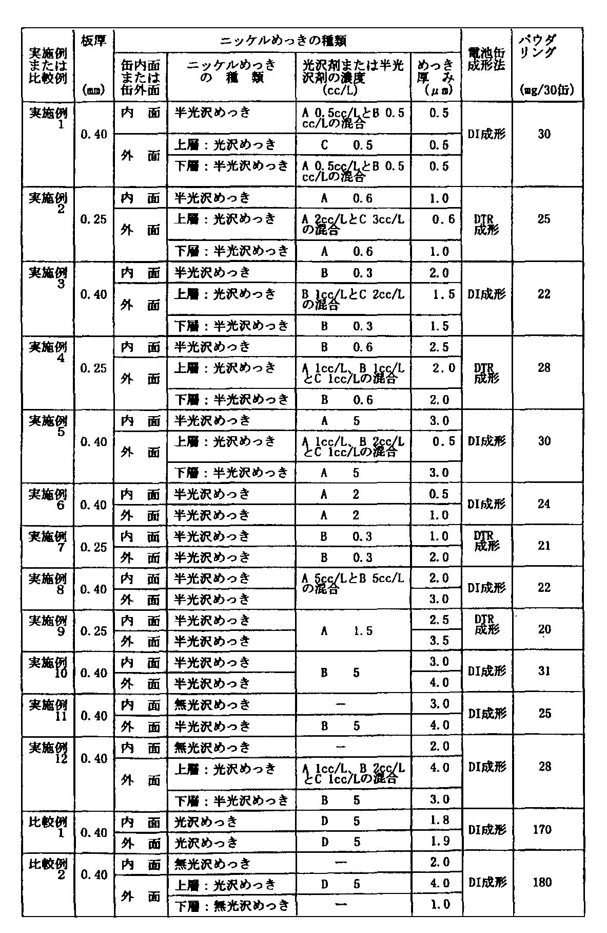
上記の条件で、光沢剤の添加量および電解時間を変えて、めっき厚を変化させた。上記の半光沢ニッケルめっきおよび光沢ニッケルめっきを行った後、めっき厚とめっき被膜合金組成はめっき層を3%硝酸に溶解し、ICP(誘導結合プラズマ発光分光分析)法によって分析した。めっき厚は溶解した各元素の量をめっき面積で除して各元素の比重を勘案してめっき厚(μm)とした。それらの結果を表1に示す。なお、表1において、光沢剤または半光沢剤として不飽和カルボン酸ホルムアルデヒドはAで、ポリオキシーエチレン付加物はBで、含窒素複素還化合物と含窒素脂肪族化合物の混合物はCで、ベンゼンスルフォン酸誘導体はDでそれぞれ示した。また、実施例8と実施例11についてはめっき後、圧延率0.5%の調質圧延を行った。
【0019】
(電池ケース作製)
DI成形法による電池ケースの成形は、板厚0.4mmの上記めっき鋼板を用い直径41mmのブランク径から直径20.5mmのカッピングの後、DI成形機でリドロ−および2段階のしごき成形を行って外径13.8mm、ケース壁0.20mm、高さ56mmに成形した。最終的に上部をトリミングして、高さ49.3mmのLR6型電池ケースを作製した。
一方:DTR成形法の電池ケースの作製は、板厚0.25mmのめっき鋼板を用い、ブランク径58mmに打ち抜き、数回の絞り、再絞り成形によって外径13.8mm、ケース壁0.20mm、高さ49.3mmのLR6型電池ケースを作製した。
【0020】
(パウダリング性評価)
パウダリング性の評価は、上記電池ケースの作製過程における、成形前後、すなわち、ブランク打ち抜き→カッピング→脱脂→重量測定(1)→成形→脱脂→重量測定(2)の重量減によりパウダリング性を評価した。なお、脱脂は、アルカリ浸漬脱脂に引き続き、アセトンによる超音波洗浄を行った。この重量減は1ケースずつの測定では誤差が大きいため、30ケースを1測定単位として3回繰り返し、測定を行った。その結果を表1に示す。
表1から明らかなように、比較例は、脱落したパウダー量が170〜180mg/30ケースと大きな値をとっているのに対し、本発明の実施例1〜12は、いずれも、脱落したパウダー量が20〜31mg/30ケースと小さな値となっている。このことは、本発明に係る電池ケースがパウダリング性に優れていることを示している。
【0021】
【表1】
【産業上の利用可能性】
本発明の電池ケースは、前記半光沢ニッケルめっき層が硫黄含有半光沢剤を含まないことを特徴とする。ここに、半光沢ニッケルめっきはパウダリング性が著しく低減できるので、カッピング工程でパンチ荷重を低くすることができ、金属接触によるダイおよびパンチの疵の発生が抑えられるため、金型寿命が伸び、電池ケースの連続生産性を向上することができる。【Technical field】
The present invention relates to a container enclosing an alkaline solution, more specifically to a battery case such as an alkaline manganese battery or a nickel cadmium battery, and a surface-treated steel sheet for a battery case that can be suitably used for producing the case.
[0002]
[Background]
Conventionally, a battery case enclosing a strong alkaline solution such as an alkaline manganese battery or a nickel cadmium battery is formed by pressing a cold-rolled steel strip into a battery case and then barrel-plating or using a nickel-plated steel strip as a battery case. The press molding method has been employed. As described above, nickel plating is used for battery applications such as alkaline manganese batteries and nickel cadmium batteries, because these batteries mainly use strong alkaline potassium hydroxide as an electrolyte, so that nickel is resistant to alkali corrosion resistance. It is strong, and when connecting the battery to the external terminal, nickel has a stable contact resistance. Further, when the battery is manufactured, each component is welded and spot welding is performed when it is assembled to the battery. However, nickel has the advantage of being excellent in spot weldability.
[0003]
By the way, in recent years, in the barrel plating method, it is difficult to uniformly deposit nickel plating particularly on the inner surface of the case, the plating thickness varies widely, and the steel strip is preliminarily coated due to unstable quality. The pre-plating method used has been the mainstream. As for the pre-plating method, in order to mainly improve the corrosion resistance, a method of applying a thermal diffusion treatment after nickel plating has been applied.
[0004]
On the other hand, the relationship between the battery performance of the alkaline manganese battery and the positive electrode case (battery case) is related to the battery performance and the properties of the inner surface of the positive electrode case. It is said that the battery performance is better when the contact resistance between the substance manganese dioxide and the conductive agent graphite and the electrolyte potassium hydroxide is lower. In the case of an alkaline manganese battery, the positive electrode mixture and the positive electrode case are in contact with each other, and the positive electrode case is a conductor for transferring and receiving electrons together with the battery container. Therefore, when the contact resistance between the positive electrode mixture and the inner surface of the positive electrode case is high, the internal resistance of the battery increases, resulting in a decrease in operating voltage or a decrease in discharge duration, thereby impairing battery performance. Therefore, it is desired to reduce the contact resistance between the positive electrode mixture and the inner surface of the positive electrode case. For this reason, in order to reduce the contact resistance between the positive electrode mixture and the positive electrode case, the surface roughness of the inner surface of the positive electrode case is increased, or a groove is formed in the vertical direction of the positive electrode case, or a conductive paint. There has also been proposed a method of applying a conductive agent in which a binder is added to graphite.
[0005]
Further, in recent years, as a press forming method for battery cases, a DI (drawing and ironing) forming method has been used as a thinning method instead of the multistage deep drawing method in order to increase the battery capacity (special feature). No. 7-99686). This DI molding method and DTR (drawing thin and redraw) molding method can accommodate more positive and negative electrode active materials by the thickness of the case side wall than the bottom surface thickness, and can increase the capacity of the battery and the case bottom. Since it is thick, there is an advantage that an improvement in the pressure strength of the battery can be obtained.
[0006]
By the way, as described above, the DI molding method and the DTR molding method are effective molding methods for increasing the battery capacity. On the other hand, in terms of moldability, compared to the conventional multistage deep drawing molding method, Since the deformation resistance of is large, it has a disadvantageous aspect in continuous formability.
Specifically, if the powdering property (powder removal of the plating layer) in the cupping process of the DI molding method or DTR molding method is inferior, it adheres to the die and punch in the ironing process, and as a result, wrinkles are formed on the case side wall. Will occur. This phenomenon also occurs in deep drawing, but the DI molding method and DTR molding method have a small surface roughness on the case wall and a more glossy appearance. The DI molding method and the DTR molding method are more important for the quality of powdering. In addition, since the contact surface pressure between the material and the tool is higher in the DI molding method and the DTR molding method than in the drawing molding, good lubricity is required from the viewpoint of tool life. Therefore, a material with good powdering property and good press lubricant retention is required from the material aspect.
[0007]
First, as a means for improving the retention of the lubricant by using a nickel-plated steel sheet, it is conceivable to cause a crack in the plated layer during press forming, and keep the crack in the lubrication. As means for this purpose, generally bright nickel plating having a high hardness of the plating layer can be conceived. However, the bright nickel-plated single layer has the disadvantage that the bright plated layer is brittle and has poor brittleness and poor powdering properties during press molding. Further, on the outer surface of the battery case, cracks are generated by processing in the bright nickel-plated single layer, and corrosion resistance is inferior due to iron exposure at the crack portion. As a method for improving the corrosion resistance, a method of performing bright nickel plating on the matte nickel plating can be considered. However, in order to obtain an effective gloss (smoothness), the gloss nickel plating layer is made thicker, or a large amount of expensive brightener is added to increase the gloss, but the cost increases. . Furthermore, since it contains a sulfur-containing organic additive (for example, sulfonic acid having a ═C—SO 2 — group) for refining the crystal grains of electrodeposition, DI molding, ironing for DTR molding, and stretching process The increase in the material temperature promotes embrittlement due to sulfur and further deteriorates the powdering resistance.
[0008]
Therefore, the present inventors have studied various battery case materials excellent in moldability and battery performance in the DI molding method and the DTR molding method from such a viewpoint. As a result, the semi-gloss that does not contain a sulfur-containing organic additive. It has been found that the nickel plating layer exhibits excellent properties in powdering resistance.
Further, after nickel plating, temper rolling may be performed. When temper rolling is performed, the glossiness increases and the appearance improves. For example, a sample having a gloss (JIS Z 8741, specular gloss measurement method) of 900 after semi-bright nickel plating is improved to 960 when subjected to temper rolling at a rolling rate of 0.5%. To do. And the corrosion resistance of a process part is not deteriorated by temper rolling, but is comparable.
The present invention has been made based on such knowledge, and provides a battery case having high quality and excellent continuous formability, and a surface-treated steel sheet that can be suitably used for producing the battery case. Doing this is a technical issue.
[0009]
DISCLOSURE OF THE INVENTION
In the battery case of the present invention, a semi-bright nickel plating layer is formed on the inner surface of the battery case, a semi-bright nickel plating layer is formed on the lower layer, and a bright nickel plating layer is formed on the upper layer. It is characterized by that.
In the battery case of the present invention, a matte nickel plating layer is formed on the inner surface of the battery case, a semi-glossy nickel plating layer is formed on the lower layer, and a bright nickel plating layer is formed on the upper layer. It is characterized by.
The battery case of the present invention is characterized in that a matte nickel plating layer is formed on the inner surface of the battery case and a semi-bright nickel plating layer is formed on the outer surface of the battery case.
The surface-treated steel sheet for a battery case of the present invention has a semi-bright nickel plating layer formed on the side that becomes the battery case inner surface, and a semi-bright nickel plating layer formed on the lower layer on the side that becomes the battery case outer surface. And a bright nickel plating layer is formed on the upper layer.
The surface-treated steel sheet for a battery case of the present invention has a matte nickel plating layer formed on the side that becomes the battery case inner surface, and a semi-glossy nickel plating layer formed on the lower layer on the side that becomes the battery case outer surface. And a bright nickel plating layer is formed on the upper layer.
The surface-treated steel sheet for a battery case of the present invention has a matte nickel plating layer formed on the side that becomes the battery case inner surface, and a semi-bright nickel plating layer formed on the side that becomes the battery case outer surface. Features.
[0010]
BEST MODE FOR CARRYING OUT THE INVENTION
The generation of semi-bright nickel plating in the above battery case and surface-treated steel sheet will be described. When a semi-bright agent not containing a sulfur-containing organic additive is added to the Watt bath and sulfamic acid bath, the semi-bright agent is co-deposited with nickel. As a result, the eutectoid plated layer increases the hardness of the plated coating layer as the semi-brightening agent content in the plated coating increases. Specifically, the plating surface hardness of the nickel sulfate bath is about 340 to 370 (Vickers hardness) when the semi-gloss agent is not added, whereas it is 350 when the semi-gloss agent is added at 2 to 3 cc / l. ˜420 (Vickers hardness).
Thus, a semi-bright nickel-plated steel plate was prepared, and this semi-bright nickel-plated steel plate was formed by the DI forming method and the DTR forming method to prepare a battery case (alkali manganese battery LR6 type).
[0011]
In addition, in order to check the powdering property, remove the lubricant on the inner and outer surfaces of the battery case with an organic solvent and attach the powder from which the plating layer has fallen to the cellophane tape. As a result of observation at (magnification 25 times), it was confirmed that the powdering property was remarkably reduced.
Furthermore, in order to see the continuous formability of the battery case, the powdering property was measured by three molding methods: a deep drawing method, a DI molding method, and a DTR molding method. As a result, it was found that the surface-treated steel sheet having the semi-bright nickel plating layer according to the present invention has a lower punch load than the bright nickel-plated single layer steel sheet.
[0012]
Thus, the punch load when the surface-treated steel sheet according to the present invention is formed is lower than that of the bright nickel-plated single layer because it does not contain a sulfur-containing semi-brightening agent. In the ironing process of molding and the stretching process of DTR molding, it is considered that the frictional resistance is lowered and the punch load is reduced.
As a result of the reduced punch load, the occurrence of die and punch wrinkles due to metal contact is suppressed, so that it is a great advantage that the mold life is extended and the continuous productivity of the battery case is improved. Next, the low frictional resistance is advantageous for battery case detachability (stripping), which is an important factor in DI moldability and DTR moldability.
Note that the present invention is not limited to the DI molding method and the DTR molding method as means for thinning the case wall of the battery case, and the powdering property can be improved in the conventional multistage deep drawing molding method. Can be used.
[0013]
Semi-brighter for sulfur-free semi-bright nickel plating baths is a mixture of nitrogen-containing heterocyclic compounds and nitrogen-containing aliphatic compounds, polyoxy-ethylene adducts of unsaturated alcohols or unsaturated carboxylic acid formaldehydes alone or in combination of two or more. A mixture of is good. The total amount of the semi-brightening agent is preferably in the range of 0.3 to 10 cc / l. When the addition amount of the semi-brightening agent is less than 0.3 cc / l, there is no effect on the powdering resistance to the plating layer of the semi-brightening agent. On the other hand, when the addition amount of the semi-brightening agent exceeds 10 cc / l, the surface-treated steel sheet It is uneconomical because the effect of smoothness, which is a measure of the glossiness of the toner, reaches saturation and the semi-brighter is expensive.
[0014]
The plating thickness of the surface-treated steel sheet of the present invention is in the range of 0.5 to 3.0 μm for semi-bright nickel plating on the case inner surface equivalent side, and 1.0 to 4 in total for the nickel plating thickness on the case outer surface equivalent side. A range of 0.0 μm is desirable. If the plating thickness on the inner surface of the case is less than 0.5μm, the exposure of iron in the steel substrate is high in batteries such as alkaline manganese batteries, and the corrosiveness is inferior, resulting in deterioration of battery performance due to elution of iron ions in the electrolyte. is there. On the other hand, if the plating thickness on the outer surface of the case is less than 1.0 μm, the corrosion resistance is not sufficient, and 1.0 μm or more is necessary due to rusting during the battery case pressing process, battery manufacturing process, and long-term storage.
The upper limit (3.0 μm, 4.0 μm) of the plating thickness on the inner and outer surfaces of the case is saturated when the plating thickness is larger than these values, and it is uneconomical to increase the thickness further. Because.
[0015]
As a steel plate that serves as a base material for the surface-treated steel plate, that is, a plating original plate, usually, a low carbon aluminum killed steel is suitably used. Furthermore, a cold-rolled steel strip produced by adding niobium and titanium and made from non-aging ultra-low carbon steel (carbon less than 0.01%) is also used.
And the steel strip which carried out the electrolytic cleaning, the annealing, and the temper rolling after the cold rolling by a normal method is used as a plating original plate. Then, using this plating original plate, semi-bright nickel plating is performed to produce a surface-treated steel plate. After plating, temper rolling may be performed.
The plating bath may be either a known sulfuric acid bath or a sulfamic acid bath, but a sulfuric acid bath whose bath management is relatively easy is suitable.
[0016]
【Example】
The present invention will be further specifically described with reference to the following examples.
Cold-rolled, annealed, and temper-rolled low-carbon aluminum killed steel plates having a thickness of 0.25 mm and 0.4 mm were used as plating original plates, respectively. The steel chemical composition of both plating original plates is as follows.
C: 0.04% (% is% by weight, the same applies hereinafter), Mn: 0.22%, Si: 0.01%, P: 0.012%, S: 0.006%, Al: 0.048% , N: 0.0025%, the above-mentioned plating original plate is subjected to pretreatment after alkaline electrolytic degreasing, water washing, sulfuric acid immersion, water washing by a conventional method, followed by semi-bright nickel plating under the following conditions, and a surface-treated steel sheet Was made.
[0017]
1) Semi-bright nickel plating It was prepared by adding a semi-bright agent to the following nickel sulfate bath.
Bath composition nickel sulfate NiSO 4 · 6H 2 O 320g / l
Nickel chloride NiCl 2 · 6H 2 O 10g / l
Boric acid H 3 BO 3 40 g / l
Bath pH: 4 (adjusted with sulfuric acid)
Stirring: Air stirring bath temperature: 60 ° C
Cathode current density: 10 A / dm 2
Anode: S pellets (trade name, manufactured by INCO, spherical shape) loaded in a titanium basket and covered with a polyprolene bag are used.
As the semi-brightener, unsaturated carboxylic acid formaldehyde or polyoxy-ethylene adduct was used. Under the above conditions, the addition amount of the semi-brightening agent and the electrolysis time were changed to change the glossiness and the plating thickness.
[0018]
2) Bright nickel plating Bright nickel plating was performed by adding a brightener to the nickel sulfate bath. A benzenesulfonic acid derivative was used as a brightener containing sulfur, and a mixture of a nitrogen-containing heterocyclic compound and a nitrogen-containing aliphatic compound was used as a brightener not containing sulfur.
Bath composition nickel sulfate NiSO 4 · 6H 2 O 300g / l
Boric acid H 3 BO 3 45 g / l
Bath temperature: 50 ° C
Cathode current density: 10 A / dm 2
Anode: S pellets (trade name, manufactured by INCO, spherical shape) loaded in a titanium basket and covered with a polyprolene bag are used.
Under the above conditions, the plating thickness was changed by changing the addition amount of the brightener and the electrolysis time. After performing the above-mentioned semi-bright nickel plating and bright nickel plating, the plating thickness and the plating film alloy composition were analyzed by ICP (inductively coupled plasma emission spectroscopy) method by dissolving the plating layer in 3% nitric acid. The plating thickness was determined by dividing the amount of each dissolved element by the plating area and taking into account the specific gravity of each element, thereby obtaining the plating thickness (μm). The results are shown in Table 1. In Table 1, as the brightener or semi-brightener, the unsaturated carboxylic acid formaldehyde is A, the polyoxyethylene adduct is B, the mixture of the nitrogen-containing heterocyclic compound and the nitrogen-containing aliphatic compound is C, and benzenesulfone The acid derivatives are indicated by D, respectively. Moreover, about Example 8 and Example 11, temper rolling with a rolling rate of 0.5% was performed after plating.
[0019]
(Battery case fabrication)
The battery case is formed by the DI forming method using the above-mentioned plated steel sheet having a thickness of 0.4 mm, cupping from a blank diameter of 41 mm to a diameter of 20.5 mm, and then performing redo and two-stage ironing with a DI molding machine. The outer diameter was 13.8 mm, the case wall was 0.20 mm, and the height was 56 mm. Finally, the upper part was trimmed to produce an LR6 type battery case having a height of 49.3 mm.
On the other hand: The battery case of the DTR forming method was prepared by using a plated steel plate having a thickness of 0.25 mm, punched to a blank diameter of 58 mm, drawn several times, and redrawed to an outer diameter of 13.8 mm, a case wall of 0.20 mm, An LR6 type battery case having a height of 49.3 mm was produced.
[0020]
(Powdering property evaluation)
The evaluation of the powdering property is based on the powdering property before and after molding, that is, blanking, cupping, degreasing, weight measurement (1), molding, degreasing, weight measurement (2) in the battery case manufacturing process. evaluated. In addition, the degreasing | defatting performed the ultrasonic cleaning by acetone following alkali immersion degreasing. Since this weight loss has a large error in the measurement for each case, the measurement was repeated three times with 30 cases as one measurement unit. The results are shown in Table 1.
As is clear from Table 1, in the comparative examples, the amount of powder dropped off was as large as 170 to 180 mg / 30 cases, whereas in Examples 1 to 12 of the present invention, all of the powders dropped off. The amount is as small as 20 to 31 mg / 30 cases. This has shown that the battery case which concerns on this invention is excellent in powdering property.
[0021]
[Table 1]
[Industrial applicability]
The battery case of the present invention is characterized in that the semi-bright nickel plating layer does not contain a sulfur-containing semi-bright agent. Here, the semi-bright nickel plating can remarkably reduce the powdering property, so the punch load can be lowered in the cupping process, and the occurrence of die and punch wrinkles due to metal contact is suppressed, so the mold life is extended, Continuous productivity of the battery case can be improved.
Claims (6)
【0001】A surface-treated steel sheet for a battery case, wherein a matte nickel plating layer is formed on the inner side of the battery case and a semi-glossy nickel plating layer is formed on the outer side of the battery case.
[0001]
Applications Claiming Priority (2)
| Application Number | Priority Date | Filing Date | Title |
|---|---|---|---|
| JP11667299 | 1999-04-23 | ||
| PCT/JP2000/002602 WO2000065672A1 (en) | 1999-04-23 | 2000-04-20 | Battery case and surface treated steel sheet for battery case |
Publications (1)
| Publication Number | Publication Date |
|---|---|
| JP3678347B2 true JP3678347B2 (en) | 2005-08-03 |
Family
ID=14693046
Family Applications (1)
| Application Number | Title | Priority Date | Filing Date |
|---|---|---|---|
| JP2000614520A Expired - Lifetime JP3678347B2 (en) | 1999-04-23 | 2000-04-20 | Battery case and surface-treated steel sheet for battery case |
Country Status (3)
| Country | Link |
|---|---|
| JP (1) | JP3678347B2 (en) |
| AU (1) | AU3841100A (en) |
| WO (1) | WO2000065672A1 (en) |
Cited By (1)
| Publication number | Priority date | Publication date | Assignee | Title |
|---|---|---|---|---|
| CN109689942A (en) * | 2016-09-13 | 2019-04-26 | 东洋钢钣株式会社 | The manufacturing method of battery case surface treated steel plate |
Families Citing this family (3)
| Publication number | Priority date | Publication date | Assignee | Title |
|---|---|---|---|---|
| KR100696929B1 (en) * | 2002-04-22 | 2007-03-20 | 도요 고한 가부시키가이샤 | Surface treated steel sheet for battery case, battery case and battery using the case |
| JP5108342B2 (en) * | 2007-03-15 | 2012-12-26 | Fdkエナジー株式会社 | Metal parts for batteries and batteries |
| JP6860087B2 (en) * | 2017-12-07 | 2021-04-14 | 株式会社豊田自動織機 | Power storage device, manufacturing method of power storage device, and electrolytic plating method |
Family Cites Families (5)
| Publication number | Priority date | Publication date | Assignee | Title |
|---|---|---|---|---|
| JPS5325538B2 (en) * | 1974-02-28 | 1978-07-27 | ||
| TW430698B (en) * | 1996-05-09 | 2001-04-21 | Toyo Kohan Co Ltd | Surface-Treatment Steel plate for battery case, its manufacture, battery case and battery |
| TW338071B (en) * | 1996-05-09 | 1998-08-11 | Toyo Koban Kk | A battery container and surface treated steel sheet for battery container |
| JP3432521B2 (en) * | 1996-05-23 | 2003-08-04 | 東洋鋼鈑株式会社 | Plated steel sheet for battery case, method for manufacturing the same, battery case, and battery |
| CN1212680C (en) * | 1996-09-03 | 2005-07-27 | 东洋钢钣株式会社 | Surface treatment steel plate for battery case, battery case and battery using the case |
-
2000
- 2000-04-20 JP JP2000614520A patent/JP3678347B2/en not_active Expired - Lifetime
- 2000-04-20 AU AU38411/00A patent/AU3841100A/en not_active Abandoned
- 2000-04-20 WO PCT/JP2000/002602 patent/WO2000065672A1/en active Application Filing
Cited By (1)
| Publication number | Priority date | Publication date | Assignee | Title |
|---|---|---|---|---|
| CN109689942A (en) * | 2016-09-13 | 2019-04-26 | 东洋钢钣株式会社 | The manufacturing method of battery case surface treated steel plate |
Also Published As
| Publication number | Publication date |
|---|---|
| WO2000065672A1 (en) | 2000-11-02 |
| AU3841100A (en) | 2000-11-10 |
Similar Documents
| Publication | Publication Date | Title |
|---|---|---|
| JP3429319B2 (en) | Battery case and surface treated steel sheet for battery case | |
| JP4808834B2 (en) | Surface-treated steel sheet for battery case | |
| WO1995011527A1 (en) | Surface-treated steel sheet for battery case and battery case | |
| KR102479919B1 (en) | Manufacturing method of surface-treated steel sheet for battery container | |
| KR100428831B1 (en) | Surface-treated steel plate for battery case, battery case and battery using the case | |
| US7150939B2 (en) | Surface-treated steel sheet for battery container, a battery container, and a battery using same | |
| JP2963318B2 (en) | Surface treated steel sheet for battery case and battery case | |
| JP3678347B2 (en) | Battery case and surface-treated steel sheet for battery case | |
| JP3631143B2 (en) | Battery case and surface-treated steel sheet for battery case | |
| JP3272866B2 (en) | Surface treated steel sheet for alkaline battery case, alkaline battery case and alkaline battery | |
| JP2534604B2 (en) | Highly workable nickel-tin plated steel strip for battery cases | |
| JP6798979B2 (en) | Manufacturing method of surface-treated steel sheet for battery container and surface-treated steel sheet for battery container | |
| JP2002155394A (en) | Surface-treated steel plate for battery case, method of manufacturing surface-treated steel plate for battery case, and battery case | |
| JP2784746B2 (en) | Battery case | |
| JP4911952B2 (en) | Plated steel sheet for battery container, battery container using the plated steel sheet for battery container, and battery using the battery container | |
| JP4968877B2 (en) | Plated steel sheet for battery container, method for producing the same, battery container using the plated steel sheet for battery container, and battery using the battery container | |
| JP2012114097A (en) | Plated steel sheet for battery container, method for producing the same, battery container using the plated steel sheet for battery container and battery using the battery container | |
| JPS5917198B2 (en) | Seamless can manufacturing method | |
| JP2004288653A (en) | Surface treated steel plate for battery case, battery case, and battery using it |
Legal Events
| Date | Code | Title | Description |
|---|---|---|---|
| A131 | Notification of reasons for refusal |
Free format text: JAPANESE INTERMEDIATE CODE: A131 Effective date: 20041214 |
|
| A521 | Request for written amendment filed |
Free format text: JAPANESE INTERMEDIATE CODE: A523 Effective date: 20050214 |
|
| A131 | Notification of reasons for refusal |
Free format text: JAPANESE INTERMEDIATE CODE: A131 Effective date: 20050325 |
|
| A521 | Request for written amendment filed |
Free format text: JAPANESE INTERMEDIATE CODE: A523 Effective date: 20050330 |
|
| TRDD | Decision of grant or rejection written | ||
| A01 | Written decision to grant a patent or to grant a registration (utility model) |
Free format text: JAPANESE INTERMEDIATE CODE: A01 Effective date: 20050506 |
|
| A61 | First payment of annual fees (during grant procedure) |
Free format text: JAPANESE INTERMEDIATE CODE: A61 Effective date: 20050506 |
|
| R150 | Certificate of patent or registration of utility model |
Ref document number: 3678347 Country of ref document: JP Free format text: JAPANESE INTERMEDIATE CODE: R150 Free format text: JAPANESE INTERMEDIATE CODE: R150 |
|
| FPAY | Renewal fee payment (event date is renewal date of database) |
Free format text: PAYMENT UNTIL: 20080520 Year of fee payment: 3 |
|
| FPAY | Renewal fee payment (event date is renewal date of database) |
Free format text: PAYMENT UNTIL: 20090520 Year of fee payment: 4 |
|
| R250 | Receipt of annual fees |
Free format text: JAPANESE INTERMEDIATE CODE: R250 |
|
| FPAY | Renewal fee payment (event date is renewal date of database) |
Free format text: PAYMENT UNTIL: 20090520 Year of fee payment: 4 |
|
| FPAY | Renewal fee payment (event date is renewal date of database) |
Free format text: PAYMENT UNTIL: 20100520 Year of fee payment: 5 |
|
| R250 | Receipt of annual fees |
Free format text: JAPANESE INTERMEDIATE CODE: R250 |
|
| FPAY | Renewal fee payment (event date is renewal date of database) |
Free format text: PAYMENT UNTIL: 20110520 Year of fee payment: 6 |
|
| R250 | Receipt of annual fees |
Free format text: JAPANESE INTERMEDIATE CODE: R250 |
|
| R250 | Receipt of annual fees |
Free format text: JAPANESE INTERMEDIATE CODE: R250 |
|
| FPAY | Renewal fee payment (event date is renewal date of database) |
Free format text: PAYMENT UNTIL: 20120520 Year of fee payment: 7 |
|
| FPAY | Renewal fee payment (event date is renewal date of database) |
Free format text: PAYMENT UNTIL: 20130520 Year of fee payment: 8 |
|
| R250 | Receipt of annual fees |
Free format text: JAPANESE INTERMEDIATE CODE: R250 |
|
| FPAY | Renewal fee payment (event date is renewal date of database) |
Free format text: PAYMENT UNTIL: 20140520 Year of fee payment: 9 |
|
| R250 | Receipt of annual fees |
Free format text: JAPANESE INTERMEDIATE CODE: R250 |
|
| R250 | Receipt of annual fees |
Free format text: JAPANESE INTERMEDIATE CODE: R250 |
|
| R250 | Receipt of annual fees |
Free format text: JAPANESE INTERMEDIATE CODE: R250 |
|
| R250 | Receipt of annual fees |
Free format text: JAPANESE INTERMEDIATE CODE: R250 |
|
| R250 | Receipt of annual fees |
Free format text: JAPANESE INTERMEDIATE CODE: R250 |
|
| R250 | Receipt of annual fees |
Free format text: JAPANESE INTERMEDIATE CODE: R250 |
|
| R250 | Receipt of annual fees |
Free format text: JAPANESE INTERMEDIATE CODE: R250 |
|
| EXPY | Cancellation because of completion of term |