EP0939189A2 - Remote control door mechanisms - Google Patents
Remote control door mechanisms Download PDFInfo
- Publication number
- EP0939189A2 EP0939189A2 EP99301396A EP99301396A EP0939189A2 EP 0939189 A2 EP0939189 A2 EP 0939189A2 EP 99301396 A EP99301396 A EP 99301396A EP 99301396 A EP99301396 A EP 99301396A EP 0939189 A2 EP0939189 A2 EP 0939189A2
- Authority
- EP
- European Patent Office
- Prior art keywords
- door
- frame
- bolt
- shaft
- motor
- Prior art date
- Legal status (The legal status is an assumption and is not a legal conclusion. Google has not performed a legal analysis and makes no representation as to the accuracy of the status listed.)
- Withdrawn
Links
Images

Classifications
-
- E—FIXED CONSTRUCTIONS
- E05—LOCKS; KEYS; WINDOW OR DOOR FITTINGS; SAFES
- E05F—DEVICES FOR MOVING WINGS INTO OPEN OR CLOSED POSITION; CHECKS FOR WINGS; WING FITTINGS NOT OTHERWISE PROVIDED FOR, CONCERNED WITH THE FUNCTIONING OF THE WING
- E05F15/00—Power-operated mechanisms for wings
- E05F15/60—Power-operated mechanisms for wings using electrical actuators
- E05F15/603—Power-operated mechanisms for wings using electrical actuators using rotary electromotors
- E05F15/665—Power-operated mechanisms for wings using electrical actuators using rotary electromotors for vertically-sliding wings
- E05F15/668—Power-operated mechanisms for wings using electrical actuators using rotary electromotors for vertically-sliding wings for overhead wings
- E05F15/681—Power-operated mechanisms for wings using electrical actuators using rotary electromotors for vertically-sliding wings for overhead wings operated by flexible elongated pulling elements, e.g. belts
- E05F15/684—Power-operated mechanisms for wings using electrical actuators using rotary electromotors for vertically-sliding wings for overhead wings operated by flexible elongated pulling elements, e.g. belts by chains
-
- E—FIXED CONSTRUCTIONS
- E05—LOCKS; KEYS; WINDOW OR DOOR FITTINGS; SAFES
- E05D—HINGES OR SUSPENSION DEVICES FOR DOORS, WINDOWS OR WINGS
- E05D13/00—Accessories for sliding or lifting wings, e.g. pulleys, safety catches
- E05D13/10—Counterbalance devices
- E05D13/12—Counterbalance devices with springs
- E05D13/1253—Counterbalance devices with springs with canted-coil torsion springs
- E05D13/1261—Counterbalance devices with springs with canted-coil torsion springs specially adapted for overhead wings
-
- E—FIXED CONSTRUCTIONS
- E05—LOCKS; KEYS; WINDOW OR DOOR FITTINGS; SAFES
- E05D—HINGES OR SUSPENSION DEVICES FOR DOORS, WINDOWS OR WINGS
- E05D15/00—Suspension arrangements for wings
- E05D15/40—Suspension arrangements for wings supported on arms movable in vertical planes
- E05D15/44—Suspension arrangements for wings supported on arms movable in vertical planes with pivoted arms and vertically-sliding guides
- E05D15/445—Suspension arrangements for wings supported on arms movable in vertical planes with pivoted arms and vertically-sliding guides specially adapted for overhead wings
-
- E—FIXED CONSTRUCTIONS
- E05—LOCKS; KEYS; WINDOW OR DOOR FITTINGS; SAFES
- E05Y—INDEXING SCHEME RELATING TO HINGES OR OTHER SUSPENSION DEVICES FOR DOORS, WINDOWS OR WINGS AND DEVICES FOR MOVING WINGS INTO OPEN OR CLOSED POSITION, CHECKS FOR WINGS AND WING FITTINGS NOT OTHERWISE PROVIDED FOR, CONCERNED WITH THE FUNCTIONING OF THE WING
- E05Y2900/00—Application of doors, windows, wings or fittings thereof
- E05Y2900/10—Application of doors, windows, wings or fittings thereof for buildings or parts thereof
- E05Y2900/106—Application of doors, windows, wings or fittings thereof for buildings or parts thereof for garages
Definitions
- This invention relates to remote control door mechanisms particularly garage doors of the so-called up-and-over type.
- up-and-over door arrangements There are basically two types of up-and-over door arrangements, namely the retractable type in which horizontal tracks extending backwardly from the door frame for supporting the upper edge of the door panel when it is opened and the canopy-type in which the door panel is suspended on pivoted links and a spring loaded lifting arrangement is provided for counterbalancing the door panel.
- the latter type is the less expensive and the easier to install as all the parts of the door mechanism are mounted in the plane of the door opening.
- a door mechanism comprising the combination of:
- the door frame, the door panel, the suspension means, the counterbalancing means, and the power operable door operating means are supplied pre-assembled and ready to attach in a door opening.
- the amount of skill required by the installer is much reduced as compared with the prior art arrangements.
- the frame is of inverted U-shaped configuration and the power-operable door operating means is mounted on the upper member of the frame.
- the counterbalancing means includes a rotary shaft
- the door operating means comprises a motor which is operatively coupled to the door via the rotary shaft.
- the motor is preferably coupled to the shaft via a clutch.
- the door mechanism preferably also includes a bolt on the door and the motor may also be arranged to drive a capture device for drivingly engaging the bolt and displacing the latter between closed and partially open positions.
- the invention also has as an object to provide a convenient form of door operating mechanism which is both inexpensive to construct and reliable in operation.
- a power operable door operating mechanism for a canopy-type up-and-over door which includes a motor driven door bolt capture device for drivingly engaging a bolt on the door and displacing the latter between closed and partially opened positions, means for detecting positioning of the door in said partially open position and motor driven means for applying rotary movement to a shaft forming part of door counterbalancing means for urging the door from its partially open position towards a fully open position.
- the same motor is employed for driving said bolt capture device and said means for applying rotary movement to said shaft.
- said means for applying torque to said shaft includes a clutch arrangement under the control of said door position detecting means to be disengaged when the door is between said partially open position and said closed position.
- said bolt capture means comprises a drive chain with which the bolt is engageable which chain transmits torque to the clutch input side.
- the door arrangement comprises a rigid inverted U-shaped outer door frame 10 on which a door panel 11 is suspended by door suspension means.
- the suspension means is of a type which is already known in principle, comprising a shaft 12 extending along the top of the door opening, counterbalancing spring means 13 for applying torque to the shaft 12, a pair of links 14 each pivotally connected at one end to a bracket 15 on the frame and at the other end to the door panel, and means, in the present case a pair of drive chains 16 on sprockets 17 on the shaft, connecting the shaft points on the door panel below the lower ends of the links 14 when the door is closed.
- Suspension means of this type usually includes a single long counterbalancing spring, but in the present construction two such springs are employed respectively acting on opposite end portions of the shaft.
- the points to which the chains 16 are connected are shown in more detail in Figure 1A, from which it will be seen that there is a guide pin 18 fixed to the door at each such point and projecting into a guide channel 19 attached to the adjacent vertical leg of the frame 10.
- a roller 20 on the pin fits in the channel to provide a smooth low friction guide action.
- Each chain 16 has its two ends connected to a link 21 on the pin 18.
- the chain may be contained within the door frame 10 and the guide channel 19.
- Figure 1B An example of this is shown in Figure 1B, in which the frame 10 has side members made up of a closed channel, with a box section secured inside it. One run of the chain is in the box section.
- the door suspension itself operates in a substantially conventional manner, that is to say the springs 13 are pre-tensioned to provide drive torque to the shaft 12.
- This drive torque causes the chains 16 to apply an upward force on the pins 18, but as these pins 18 lie directly below the links 14 which extend substantially vertically when the door is closed, there is no turning moment on the door. It is possible, however, in the absence of any locks, bolts or latches holding the door shut, to push the upper part of the door inwardly which results in a turning moment being applied to the door by the springs 13 via the chains 16. Initially this moment is small, but as the links 14 swing inwardly and the pins 18 travel up the guides 19, the moment increases, although the torque produced by the spring increases.
- the linkage geometry and the spring pre-tension are such that, at the closed end of the door travel the moment of the door's weight exceeds the moment of the counterbalancing torque so that the door is urged shut. At the opposite end of the door travel the door is urged open by the combined effects of gravity and the counterbalancing springs.
- a drive gear which as shown in Figure 2, when actuated, initially tilts the door to a partially open position and then drives the door fully open by turning the shaft 12.
- the drive gear comprises a drive chassis 30 attached to the upper rail of the door frame at the centre thereof.
- a drive motor 31 mounted on the chassis 30, provides drive action to a sprocket spindle 32 via a worm and pinion drive 33.
- a sprocket 34 on the spindle 32 is engaged with an endless chain 35 which also extends around a similar sprocket forming the input member of a friction clutch 37 the output member of which is fast with the shaft 12.
- the clutch 37 is operated by a spring 38 on the shaft 12 which urges the clutch parts into driving engagement.
- a lever 39 pivotally mounted at one end on the chassis is provided for disengaging the clutch by relieving the force applied by spring 38 when required.
- the chain 35 forms part of a door bolt capture arrangement.
- a bolt 41 mounted on the upper part of the door has a notched end to enable it to engage lugs provided on opposite sides of the chain.
- the upper part of the door is moved towards or away from the frame depending on the direction of drive.
- the bolt 41 also co-acts with the lever 39 to form a door position detecting means.
- the bolt 41 When the bolt 41 is engaged with the chain 35, it also engages the lever, turning it against the spring loading to disengage the clutch.
- the bolt causes the clutch 37 to disengage. If the motor is driven in door opening position, the bolt is carried away from the frame, opening the door, until the bolt eventually becomes disengaged from both the chain 35 and the lever 39.
- the clutch 37 is now engaged so that continued rotation of the motor shaft is transmitted via the chain 35 and the clutch 37 to the spindle 12, thereby raising the pins 18 and continuing opening movement of the door.
- the bolt 41 can be manually withdrawn downwardly out of engagement with the chain 35 and lever 39. This allows some inward movement of the upper edge of the door to be initiated, but as the clutch becomes engaged when the bolt is withdrawn such movement is limited.
- a separate mechanism is provided for displacing lever 39 when required to release the clutch.
- This mechanism employs a cam 42 in a hole in the lever 39. The cam can be turned by a knob, handle or key on the underside of the chassis.
- an L-shaped manual release lever is pivotally mounted by a vertical pivot pin in a pressed steel chassis having an inverted channel section in which the chain 35 and sprockets, the clutch 36 and a clutch lever (having a similar function to lever 39) are mounted.
- a clutch-adjacent end of the clutch lever is pivotally mounted on the chassis via a vertical pivot pin.
- One of the arms of the manual release lever projects through a slot in an end plate fitted to the inner end of the chassis so that such arm is exposed for manual operation.
- the other arm of the manual release lever is engageable with the end of the clutch lever remote from the clutch so that manual pivoting of the lever can be effected to cause the clutch lever to release the motor drive transmission. It is possible to attach a release cable to the manual release lever to select manual operation from alongside the door frame (which may for example be of benefit to an elderly or infirm door operator).
- detectors are provided for sensing when the door is fully open and fully closed and for stopping the motor. These detectors may form part of a remotely controllable motor control circuit (not shown).
- the detectors may be provided as limit switches (optical, electrical or magnetic).
- One such switch or other detector may be in the chassis 30 and detects the arrival of the bolt 41 at the door closed position.
- the other may be arranged to co-act with the pin 18 to detect the door open condition.
- the detector arranged to detect the door open condition may be a motor current sensor which detects when the motor current rises as a result of the motor stalling when one of the rollers 20 engages against a rubber stop.
- the door is supplied pre-assembled with the frame so that it can be mounted very easily behind a door opening. All necessary adjustments to the mechanism can thus be made during manufacture of the door/frame assembly so as to ensure that there is no difficulty in setting up the operating gear on installation.
- a chain drive as part of the bolt capture means is particularly advantageous as it allows the same motor to drive the bolt and the shaft. It is to be understood, however, that the invention may also be realised utilising quite different bolt capture and shaft-rotating arrangements. These could, for example, be driven by two independent motors if required, and the invention also comprehends the use of door position detecting switches to switch drive between one motor and the other at the point where the limit of bolt capture drive is reached.
Landscapes
- Power-Operated Mechanisms For Wings (AREA)
- Closing And Opening Devices For Wings, And Checks For Wings (AREA)
Abstract
Description
- This invention relates to remote control door mechanisms particularly garage doors of the so-called up-and-over type.
- There are basically two types of up-and-over door arrangements, namely the retractable type in which horizontal tracks extending backwardly from the door frame for supporting the upper edge of the door panel when it is opened and the canopy-type in which the door panel is suspended on pivoted links and a spring loaded lifting arrangement is provided for counterbalancing the door panel. The latter type is the less expensive and the easier to install as all the parts of the door mechanism are mounted in the plane of the door opening. However, it is relatively difficult to provide remotely controllable power operating means for canopy-type doors as the motion of the door during opening is complex.
- Various remotely controllable power operating arrangements have, nonetheless, been proposed in the past, but these have tended to suffer from considerable complication, making installation a difficult task and requiring a precision beyond the competence of many building construction workers.
- It is one object of the present invention, therefore, to provide a door mechanism which is very simple to install.
- In accordance with one aspect of the invention there is provided, as an article of manufacture, a door mechanism comprising the combination of:
- (a) a rigid frame for mounting in a door opening;
- (b) a door panel;
- (c) door panel suspension means suspending the door in the frame for up-and-over opening movement;
- (d) door panel counterbalancing means acting between the frame and the door panel; and
- (e) power operable door operating means mounted on said frame and operatively coupled to the door.
-
- With such an arrangement, the door frame, the door panel, the suspension means, the counterbalancing means, and the power operable door operating means are supplied pre-assembled and ready to attach in a door opening. The amount of skill required by the installer is much reduced as compared with the prior art arrangements.
- Preferably the frame is of inverted U-shaped configuration and the power-operable door operating means is mounted on the upper member of the frame.
- Preferably also, the counterbalancing means includes a rotary shaft, and the door operating means comprises a motor which is operatively coupled to the door via the rotary shaft. The motor is preferably coupled to the shaft via a clutch. The door mechanism preferably also includes a bolt on the door and the motor may also be arranged to drive a capture device for drivingly engaging the bolt and displacing the latter between closed and partially open positions.
- The invention also has as an object to provide a convenient form of door operating mechanism which is both inexpensive to construct and reliable in operation.
- In accordance with this aspect of the invention, there is provided a power operable door operating mechanism for a canopy-type up-and-over door which includes a motor driven door bolt capture device for drivingly engaging a bolt on the door and displacing the latter between closed and partially opened positions, means for detecting positioning of the door in said partially open position and motor driven means for applying rotary movement to a shaft forming part of door counterbalancing means for urging the door from its partially open position towards a fully open position.
- Preferably, the same motor is employed for driving said bolt capture device and said means for applying rotary movement to said shaft. Conveniently said means for applying torque to said shaft includes a clutch arrangement under the control of said door position detecting means to be disengaged when the door is between said partially open position and said closed position.
- In one convenient arrangement, said bolt capture means comprises a drive chain with which the bolt is engageable which chain transmits torque to the clutch input side.
- An example of the invention is shown in the accompanying drawings in which:
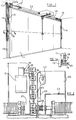
- Figure 1 is a perspective view of a door arrangement in accordance with the invention;
- Figure 1A is a fragmentary section taken on line A-A in Figure 1 and showing a guide arrangement for the door;
- Figure 1B is a fragmentary section of a modification of the arrangement shown in Figure 1A;
- Figure 2 is a plan view of part of a motorised operating gear for the door;
- Figure 3 is a view of a retractable door bolt which coacts with the operating gear; and
- Figure 4 is a fragmentary view showing the door in a partially open position.
-
- As shown in Figure 1 the door arrangement comprises a rigid inverted U-shaped
outer door frame 10 on which adoor panel 11 is suspended by door suspension means. The suspension means is of a type which is already known in principle, comprising ashaft 12 extending along the top of the door opening, counterbalancing spring means 13 for applying torque to theshaft 12, a pair oflinks 14 each pivotally connected at one end to abracket 15 on the frame and at the other end to the door panel, and means, in the present case a pair ofdrive chains 16 onsprockets 17 on the shaft, connecting the shaft points on the door panel below the lower ends of thelinks 14 when the door is closed. Suspension means of this type usually includes a single long counterbalancing spring, but in the present construction two such springs are employed respectively acting on opposite end portions of the shaft. The points to which thechains 16 are connected are shown in more detail in Figure 1A, from which it will be seen that there is aguide pin 18 fixed to the door at each such point and projecting into aguide channel 19 attached to the adjacent vertical leg of theframe 10. Aroller 20 on the pin fits in the channel to provide a smooth low friction guide action. Eachchain 16 has its two ends connected to alink 21 on thepin 18. In an alternative arrangement the chain may be contained within thedoor frame 10 and theguide channel 19. An example of this is shown in Figure 1B, in which theframe 10 has side members made up of a closed channel, with a box section secured inside it. One run of the chain is in the box section. - The door suspension itself operates in a substantially conventional manner, that is to say the
springs 13 are pre-tensioned to provide drive torque to theshaft 12. This drive torque causes thechains 16 to apply an upward force on thepins 18, but as thesepins 18 lie directly below thelinks 14 which extend substantially vertically when the door is closed, there is no turning moment on the door. It is possible, however, in the absence of any locks, bolts or latches holding the door shut, to push the upper part of the door inwardly which results in a turning moment being applied to the door by thesprings 13 via thechains 16. Initially this moment is small, but as thelinks 14 swing inwardly and thepins 18 travel up theguides 19, the moment increases, although the torque produced by the spring increases. - The linkage geometry and the spring pre-tension are such that, at the closed end of the door travel the moment of the door's weight exceeds the moment of the counterbalancing torque so that the door is urged shut. At the opposite end of the door travel the door is urged open by the combined effects of gravity and the counterbalancing springs.
- To enable the door arrangement described above to be motor driven a drive gear is provided which as shown in Figure 2, when actuated, initially tilts the door to a partially open position and then drives the door fully open by turning the
shaft 12. The drive gear comprises adrive chassis 30 attached to the upper rail of the door frame at the centre thereof. Adrive motor 31 mounted on thechassis 30, provides drive action to asprocket spindle 32 via a worm andpinion drive 33. Asprocket 34 on thespindle 32 is engaged with anendless chain 35 which also extends around a similar sprocket forming the input member of afriction clutch 37 the output member of which is fast with theshaft 12. Theclutch 37 is operated by aspring 38 on theshaft 12 which urges the clutch parts into driving engagement. Alever 39 pivotally mounted at one end on the chassis is provided for disengaging the clutch by relieving the force applied byspring 38 when required. - The
chain 35 forms part of a door bolt capture arrangement. A bolt 41 mounted on the upper part of the door has a notched end to enable it to engage lugs provided on opposite sides of the chain. Thus when the chain is driven whilst the bolt is engaged, the upper part of the door is moved towards or away from the frame depending on the direction of drive. - The bolt 41 also co-acts with the
lever 39 to form a door position detecting means. When the bolt 41 is engaged with thechain 35, it also engages the lever, turning it against the spring loading to disengage the clutch. Thus, when the door is closed, the bolt causes theclutch 37 to disengage. If the motor is driven in door opening position, the bolt is carried away from the frame, opening the door, until the bolt eventually becomes disengaged from both thechain 35 and thelever 39. Theclutch 37 is now engaged so that continued rotation of the motor shaft is transmitted via thechain 35 and theclutch 37 to thespindle 12, thereby raising thepins 18 and continuing opening movement of the door. - From the open position of the door, rotation of the motor shaft in the door closing position will initially cause progressive lowering of
pins 18 and consequent door closing movement, until the bolt 41 becomes engaged withchain 35 andlever 39. This causes the clutch to be disengaged and final closing movement is effected by capture of the bolt bychain 35. - It will be appreciated that capture of the bolt 41 by the
chain 35 effectively locks the door closed, as the chain cannot drive the motor shaft through the worm and pinion drive. Further latches may be provided at the sides of the door if required. - However, to allow manual door opening, the bolt 41 can be manually withdrawn downwardly out of engagement with the
chain 35 and lever 39. This allows some inward movement of the upper edge of the door to be initiated, but as the clutch becomes engaged when the bolt is withdrawn such movement is limited. As shown in Figure 2, however, a separate mechanism is provided for displacinglever 39 when required to release the clutch. This mechanism employs acam 42 in a hole in thelever 39. The cam can be turned by a knob, handle or key on the underside of the chassis. - In an alternative arrangement (not shown), an L-shaped manual release lever is pivotally mounted by a vertical pivot pin in a pressed steel chassis having an inverted channel section in which the
chain 35 and sprockets, the clutch 36 and a clutch lever (having a similar function to lever 39) are mounted. A clutch-adjacent end of the clutch lever is pivotally mounted on the chassis via a vertical pivot pin. One of the arms of the manual release lever projects through a slot in an end plate fitted to the inner end of the chassis so that such arm is exposed for manual operation. The other arm of the manual release lever is engageable with the end of the clutch lever remote from the clutch so that manual pivoting of the lever can be effected to cause the clutch lever to release the motor drive transmission. It is possible to attach a release cable to the manual release lever to select manual operation from alongside the door frame (which may for example be of benefit to an elderly or infirm door operator). - Although not shown in the drawings, detectors are provided for sensing when the door is fully open and fully closed and for stopping the motor. These detectors may form part of a remotely controllable motor control circuit (not shown). The detectors may be provided as limit switches (optical, electrical or magnetic). One such switch or other detector may be in the
chassis 30 and detects the arrival of the bolt 41 at the door closed position. The other may be arranged to co-act with thepin 18 to detect the door open condition. Alternatively, the detector arranged to detect the door open condition may be a motor current sensor which detects when the motor current rises as a result of the motor stalling when one of therollers 20 engages against a rubber stop. - As mentioned above, the door is supplied pre-assembled with the frame so that it can be mounted very easily behind a door opening. All necessary adjustments to the mechanism can thus be made during manufacture of the door/frame assembly so as to ensure that there is no difficulty in setting up the operating gear on installation.
- The use of a chain drive as part of the bolt capture means is particularly advantageous as it allows the same motor to drive the bolt and the shaft. It is to be understood, however, that the invention may also be realised utilising quite different bolt capture and shaft-rotating arrangements. These could, for example, be driven by two independent motors if required, and the invention also comprehends the use of door position detecting switches to switch drive between one motor and the other at the point where the limit of bolt capture drive is reached.
Claims (10)
- A door mechanism as an article of manufacture comprising the combination of:(a) a rigid frame for mounting in a door opening;(b) a door panel;(c) door panel suspension means suspending the door in the frame for up-and-over opening movement;(d) door panel counterbalancing means acting between the frame and the door panel; and(e) power operable door operating means mounted on said frame and operatively coupled to the door.
- A door mechanism as claimed in claim 1, wherein the frame is of inverted U-shaped configuration and the power-operable door operating means is mounted on an upper member of the frame.
- A door mechanism as claimed in claim 1 or 2, wherein the counterbalancing means includes a rotary shaft, and the door operating means comprises a motor which is operatively coupled to the door via the rotary shaft.
- A door mechanism as claimed in claim 3, wherein the motor is coupled to the shaft via a clutch.
- A door mechanism as claimed in any preceding claim, further including a bolt on the door, and wherein the motor is arranged to drive a capture device for drivingly engaging the bolt and displacing the latter between closed and partially open positions.
- A power operable door operating mechanism for a canopy-type up-and-over door which includes a motor driven door bolt capture device for drivingly engaging a bolt on the door and displacing the latter between closed and partially opened positions, means for detecting positioning of the door in said partially open position, and motor driven means for applying rotary movement to a shaft forming part of door counterbalancing means for urging the door from its partially open position towards a fully open position.
- A mechanism as claimed in claim 6, wherein the same motor is employed for driving said bolt capture device and said means for applying rotary movement to said shaft.
- A mechanism as claimed in claim 6 or 7, wherein said means for applying rotary movement to said shaft includes a clutch arrangement under the control of said door position detecting means to be disengaged when the door is between said partially open position and said closed position.
- A mechanism as claimed in claim 8, wherein said bolt capture device comprises a drive chain with which the bolt is engageable, which chain transmits torque to an input side of the clutch arrangement.
- A mechanism as claimed in claim 1 or 6, substantially as hereinbefore described with reference to the accompanying drawings.
Applications Claiming Priority (2)
| Application Number | Priority Date | Filing Date | Title |
|---|---|---|---|
| GB9803971 | 1998-02-26 | ||
| GB9803971A GB2334750A (en) | 1998-02-26 | 1998-02-26 | Power-operated door mechanisms |
Publications (2)
| Publication Number | Publication Date |
|---|---|
| EP0939189A2 true EP0939189A2 (en) | 1999-09-01 |
| EP0939189A3 EP0939189A3 (en) | 2000-05-31 |
Family
ID=10827576
Family Applications (1)
| Application Number | Title | Priority Date | Filing Date |
|---|---|---|---|
| EP99301396A Withdrawn EP0939189A3 (en) | 1998-02-26 | 1999-02-25 | Remote control door mechanisms |
Country Status (2)
| Country | Link |
|---|---|
| EP (1) | EP0939189A3 (en) |
| GB (2) | GB2344138B (en) |
Cited By (4)
| Publication number | Priority date | Publication date | Assignee | Title |
|---|---|---|---|---|
| WO2001079640A2 (en) * | 2000-04-13 | 2001-10-25 | Wayne-Dalton Corp. | Overhead door locking operator |
| US6561255B1 (en) | 2000-04-13 | 2003-05-13 | Wayne-Dalton Corp. | Overhead door locking operator |
| US7397342B2 (en) | 2004-02-19 | 2008-07-08 | Wayne-Dalton Corp. | Operating system for a motorized barrier operator with a radio frequency energized light kit and/or switch and methods for programming the same |
| ITUB20153562A1 (en) * | 2015-09-11 | 2017-03-11 | Key Automation S R L | SYSTEM OF OPERATION OF A SECTIONAL DOOR |
Families Citing this family (3)
| Publication number | Priority date | Publication date | Assignee | Title |
|---|---|---|---|---|
| FR2850421B1 (en) * | 2003-01-28 | 2006-02-10 | Systeme D Automatismes Fermetu | DEVICE FOR ASSISTING THE STARTING OF THE OPENING OF A TILTING DOOR |
| EP2960420B1 (en) | 2014-06-26 | 2020-10-14 | Serrande de Nardi - S.r.l. | Device to open/close garage doors |
| IT201700004519A1 (en) * | 2017-01-17 | 2018-07-17 | Sandrini Serrande Srl | Overhead door, comprising an improved balancing device and / or a parachute device and / or an improved fixing system. |
Citations (4)
| Publication number | Priority date | Publication date | Assignee | Title |
|---|---|---|---|---|
| US4472910A (en) * | 1982-09-29 | 1984-09-25 | Chamnberlain Manufacturing Corporation | Integral device for garage door opener |
| FR2624186A3 (en) * | 1987-12-02 | 1989-06-09 | Mueller Guenter | Up-and-over door, especially intended for garages |
| EP0524900A1 (en) * | 1991-07-24 | 1993-01-27 | Richard Bubendorff | Electro-mechanical drive device for overhead door, especially for overhead garage door |
| GB2305466A (en) * | 1995-09-20 | 1997-04-09 | Vega Ltd | Canopy door: guide linkage |
Family Cites Families (6)
| Publication number | Priority date | Publication date | Assignee | Title |
|---|---|---|---|---|
| GB1382707A (en) * | 1972-05-30 | 1975-02-05 | Henderson P C Ltd | Apparatus for opening a door window or panel of a type having top hung arms and vertical tracks |
| GB2073814B (en) * | 1980-04-03 | 1983-10-12 | Garage Door Automation Ltd | Apparatus for opening and closing a panel in a frame |
| IT1216428B (en) * | 1986-10-24 | 1990-02-28 | Silvelox Spa | GUIDE AND DRIVE EQUIPMENT OF A SWINGING SWING. |
| GB2221951B (en) * | 1988-07-14 | 1992-04-15 | Jack Metcalf | Power operated garage door opener |
| GB8927034D0 (en) * | 1989-11-29 | 1990-01-17 | Alley Patrick H | Improvement in or relating to apparatus for displacing a door or closure member |
| US5373663A (en) * | 1992-10-09 | 1994-12-20 | Aprimatic S.P.A. | Device for motorizing an overhead swinging door for a garage or the like, and motorized overhead swinging door provided with this device |
-
1998
- 1998-02-26 GB GB0004019A patent/GB2344138B/en not_active Expired - Fee Related
- 1998-02-26 GB GB9803971A patent/GB2334750A/en not_active Withdrawn
-
1999
- 1999-02-25 EP EP99301396A patent/EP0939189A3/en not_active Withdrawn
Patent Citations (4)
| Publication number | Priority date | Publication date | Assignee | Title |
|---|---|---|---|---|
| US4472910A (en) * | 1982-09-29 | 1984-09-25 | Chamnberlain Manufacturing Corporation | Integral device for garage door opener |
| FR2624186A3 (en) * | 1987-12-02 | 1989-06-09 | Mueller Guenter | Up-and-over door, especially intended for garages |
| EP0524900A1 (en) * | 1991-07-24 | 1993-01-27 | Richard Bubendorff | Electro-mechanical drive device for overhead door, especially for overhead garage door |
| GB2305466A (en) * | 1995-09-20 | 1997-04-09 | Vega Ltd | Canopy door: guide linkage |
Cited By (13)
| Publication number | Priority date | Publication date | Assignee | Title |
|---|---|---|---|---|
| WO2001079640A2 (en) * | 2000-04-13 | 2001-10-25 | Wayne-Dalton Corp. | Overhead door locking operator |
| WO2001079640A3 (en) * | 2000-04-13 | 2002-02-21 | Wayne Dalton Corp | Overhead door locking operator |
| US6561255B1 (en) | 2000-04-13 | 2003-05-13 | Wayne-Dalton Corp. | Overhead door locking operator |
| US6568454B1 (en) | 2000-04-13 | 2003-05-27 | Wayne-Dalton Corp. | Overhead door locking operator |
| US6739372B2 (en) | 2000-04-13 | 2004-05-25 | Wayne-Dalton Corp. | Overhead door locking operator |
| US6845804B2 (en) | 2000-04-13 | 2005-01-25 | Wayne-Dalton Corp. | Overhead door locking operator |
| US6851465B2 (en) | 2000-04-13 | 2005-02-08 | Wayne-Dalton Corp. | Overhead door locking operator |
| US6880609B2 (en) | 2000-04-13 | 2005-04-19 | Wayne-Dalton Corp. | Overhead door locking operator |
| US7143804B2 (en) | 2000-04-13 | 2006-12-05 | Wayne-Dalton Corp. | Overhead door locking operator with remote light assembly |
| US7246647B2 (en) | 2000-04-13 | 2007-07-24 | Wayne-Dalton Corp. | Overhead door locking operator |
| US7397342B2 (en) | 2004-02-19 | 2008-07-08 | Wayne-Dalton Corp. | Operating system for a motorized barrier operator with a radio frequency energized light kit and/or switch and methods for programming the same |
| ITUB20153562A1 (en) * | 2015-09-11 | 2017-03-11 | Key Automation S R L | SYSTEM OF OPERATION OF A SECTIONAL DOOR |
| EP3141686A1 (en) * | 2015-09-11 | 2017-03-15 | Key Automation S.r.l. | Operating system for a sectional door |
Also Published As
| Publication number | Publication date |
|---|---|
| GB2344138A (en) | 2000-05-31 |
| GB9803971D0 (en) | 1998-04-22 |
| GB2344138B (en) | 2000-10-04 |
| EP0939189A3 (en) | 2000-05-31 |
| GB0004019D0 (en) | 2000-04-12 |
| GB2334750A (en) | 1999-09-01 |
Similar Documents
| Publication | Publication Date | Title |
|---|---|---|
| US5698073A (en) | Automatic sectional door opener | |
| US8375635B2 (en) | Apparatus for opening and closing overhead sectional doors | |
| US6561255B1 (en) | Overhead door locking operator | |
| US6253824B1 (en) | Disconnect for powered sectional door | |
| US4819376A (en) | Driving and guiding apparatus for a horizontally pivoted wing | |
| AU771245B2 (en) | System and related methods for detecting a force profile deviation of a garage door | |
| PT90016B (en) | DOOR DRIVE DEVICE WITH ELEVATOR LOCK MECHANISM | |
| JPH044439B2 (en) | ||
| JP6501604B2 (en) | Automatic door device | |
| KR100704451B1 (en) | Door automatic open and shut apparatus | |
| EP0939189A2 (en) | Remote control door mechanisms | |
| US20060090861A1 (en) | Direct transmission garage door opener | |
| US4721146A (en) | Rolling door operating mechanism | |
| GB2087475A (en) | Device for Closing and Opening Blinds, Shutters, and Hinged Window Members in General | |
| EP0190025A2 (en) | Operating mechanism for an up-and-over door | |
| US5406751A (en) | Electrical operator for doors and windows | |
| US3591981A (en) | Door operator | |
| US3436863A (en) | Door operating means | |
| US5325628A (en) | Automatic door operator | |
| US5918418A (en) | Overhead door operator | |
| US3436862A (en) | Automatic door lock actuator | |
| GB2308399A (en) | Tracked canopy door with motor driven opening and closing mechanism | |
| JP2674973B2 (en) | Airtight door opening / closing device | |
| US1846514A (en) | Closure operator | |
| US3353299A (en) | Overhead door and operating means therefor |
Legal Events
| Date | Code | Title | Description |
|---|---|---|---|
| PUAI | Public reference made under article 153(3) epc to a published international application that has entered the european phase |
Free format text: ORIGINAL CODE: 0009012 |
|
| AK | Designated contracting states |
Kind code of ref document: A2 Designated state(s): AT BE CH CY DE DK ES FI FR GB GR IE IT LI LU MC NL PT SE |
|
| AX | Request for extension of the european patent |
Free format text: AL;LT;LV;MK;RO;SI |
|
| PUAL | Search report despatched |
Free format text: ORIGINAL CODE: 0009013 |
|
| AK | Designated contracting states |
Kind code of ref document: A3 Designated state(s): AT BE CH CY DE DK ES FI FR GB GR IE IT LI LU MC NL PT SE |
|
| AX | Request for extension of the european patent |
Free format text: AL;LT;LV;MK;RO;SI |
|
| STAA | Information on the status of an ep patent application or granted ep patent |
Free format text: STATUS: REQUEST FOR EXAMINATION WAS MADE |
|
| 17P | Request for examination filed |
Effective date: 20001129 |
|
| AKX | Designation fees paid |
Free format text: AT BE DE DK ES FI FR IE IT NL SE |
|
| 18D | Application deemed to be withdrawn |
Effective date: 20020903 |