EP0938910A2 - Scheidenelektrode zur Behandlung von Harninkontinenz - Google Patents
Scheidenelektrode zur Behandlung von Harninkontinenz Download PDFInfo
- Publication number
- EP0938910A2 EP0938910A2 EP99301407A EP99301407A EP0938910A2 EP 0938910 A2 EP0938910 A2 EP 0938910A2 EP 99301407 A EP99301407 A EP 99301407A EP 99301407 A EP99301407 A EP 99301407A EP 0938910 A2 EP0938910 A2 EP 0938910A2
- Authority
- EP
- European Patent Office
- Prior art keywords
- ring
- shaped
- conductive
- electrode
- bands
- Prior art date
- Legal status (The legal status is an assumption and is not a legal conclusion. Google has not performed a legal analysis and makes no representation as to the accuracy of the status listed.)
- Withdrawn
Links
- 238000011282 treatment Methods 0.000 title claims abstract description 35
- 206010046543 Urinary incontinence Diseases 0.000 title claims abstract description 15
- 239000002184 metal Substances 0.000 claims abstract description 67
- 238000003780 insertion Methods 0.000 claims abstract description 45
- 230000037431 insertion Effects 0.000 claims abstract description 45
- 239000010703 silicon Substances 0.000 claims abstract description 41
- 229910052710 silicon Inorganic materials 0.000 claims abstract description 41
- 239000012811 non-conductive material Substances 0.000 claims abstract description 35
- 238000004519 manufacturing process Methods 0.000 claims abstract description 31
- 238000000465 moulding Methods 0.000 claims abstract description 26
- 238000000034 method Methods 0.000 claims abstract description 22
- 230000003387 muscular Effects 0.000 claims abstract description 15
- 230000008569 process Effects 0.000 claims abstract description 9
- 239000011159 matrix material Substances 0.000 claims description 33
- 239000004020 conductor Substances 0.000 claims description 11
- 238000005476 soldering Methods 0.000 claims description 11
- 239000000463 material Substances 0.000 claims description 9
- 239000004033 plastic Substances 0.000 claims description 7
- 230000008878 coupling Effects 0.000 claims description 2
- 238000010168 coupling process Methods 0.000 claims description 2
- 238000005859 coupling reaction Methods 0.000 claims description 2
- 239000011796 hollow space material Substances 0.000 abstract 1
- XUIMIQQOPSSXEZ-UHFFFAOYSA-N Silicon Chemical compound [Si] XUIMIQQOPSSXEZ-UHFFFAOYSA-N 0.000 description 28
- 210000003205 muscle Anatomy 0.000 description 13
- 230000000638 stimulation Effects 0.000 description 12
- 229920001940 conductive polymer Polymers 0.000 description 8
- 210000001215 vagina Anatomy 0.000 description 7
- 230000008901 benefit Effects 0.000 description 6
- 230000002232 neuromuscular Effects 0.000 description 4
- 210000003903 pelvic floor Anatomy 0.000 description 3
- 230000003449 preventive effect Effects 0.000 description 3
- 230000001012 protector Effects 0.000 description 3
- 238000006243 chemical reaction Methods 0.000 description 2
- 238000010586 diagram Methods 0.000 description 2
- 238000002651 drug therapy Methods 0.000 description 2
- 230000000694 effects Effects 0.000 description 2
- 238000005259 measurement Methods 0.000 description 2
- 239000000047 product Substances 0.000 description 2
- 238000001356 surgical procedure Methods 0.000 description 2
- 238000002560 therapeutic procedure Methods 0.000 description 2
- XLYOFNOQVPJJNP-UHFFFAOYSA-N water Substances O XLYOFNOQVPJJNP-UHFFFAOYSA-N 0.000 description 2
- OKTJSMMVPCPJKN-UHFFFAOYSA-N Carbon Chemical compound [C] OKTJSMMVPCPJKN-UHFFFAOYSA-N 0.000 description 1
- 206010010774 Constipation Diseases 0.000 description 1
- 208000034347 Faecal incontinence Diseases 0.000 description 1
- 239000004677 Nylon Substances 0.000 description 1
- 230000002745 absorbent Effects 0.000 description 1
- 239000002250 absorbent Substances 0.000 description 1
- 239000000853 adhesive Substances 0.000 description 1
- 230000001070 adhesive effect Effects 0.000 description 1
- 230000032683 aging Effects 0.000 description 1
- 229910052799 carbon Inorganic materials 0.000 description 1
- 230000035606 childbirth Effects 0.000 description 1
- 238000004140 cleaning Methods 0.000 description 1
- 230000008602 contraction Effects 0.000 description 1
- 230000007423 decrease Effects 0.000 description 1
- 230000002950 deficient Effects 0.000 description 1
- 239000000645 desinfectant Substances 0.000 description 1
- 230000006866 deterioration Effects 0.000 description 1
- 230000009429 distress Effects 0.000 description 1
- 238000002847 impedance measurement Methods 0.000 description 1
- 239000007769 metal material Substances 0.000 description 1
- 238000012986 modification Methods 0.000 description 1
- 230000004048 modification Effects 0.000 description 1
- 210000004126 nerve fiber Anatomy 0.000 description 1
- 229920001778 nylon Polymers 0.000 description 1
- 239000012466 permeate Substances 0.000 description 1
- 238000000554 physical therapy Methods 0.000 description 1
- 229920000642 polymer Polymers 0.000 description 1
- 230000003252 repetitive effect Effects 0.000 description 1
- 239000011347 resin Substances 0.000 description 1
- 229920005989 resin Polymers 0.000 description 1
- 230000035939 shock Effects 0.000 description 1
- 229910000679 solder Inorganic materials 0.000 description 1
- 239000007787 solid Substances 0.000 description 1
- 239000011343 solid material Substances 0.000 description 1
- 238000012546 transfer Methods 0.000 description 1
Images


Classifications
-
- A—HUMAN NECESSITIES
- A61—MEDICAL OR VETERINARY SCIENCE; HYGIENE
- A61N—ELECTROTHERAPY; MAGNETOTHERAPY; RADIATION THERAPY; ULTRASOUND THERAPY
- A61N1/00—Electrotherapy; Circuits therefor
- A61N1/02—Details
- A61N1/04—Electrodes
- A61N1/05—Electrodes for implantation or insertion into the body, e.g. heart electrode
- A61N1/0521—Genital electrodes
- A61N1/0524—Vaginal electrodes
-
- A—HUMAN NECESSITIES
- A61—MEDICAL OR VETERINARY SCIENCE; HYGIENE
- A61N—ELECTROTHERAPY; MAGNETOTHERAPY; RADIATION THERAPY; ULTRASOUND THERAPY
- A61N1/00—Electrotherapy; Circuits therefor
- A61N1/02—Details
- A61N1/04—Electrodes
- A61N1/05—Electrodes for implantation or insertion into the body, e.g. heart electrode
- A61N1/0507—Electrodes for the digestive system
- A61N1/0512—Anal electrodes
Definitions
- the present invention relates to an electrode for insertion into a body cavity, and in particular, to an electrode for insertion into a vagina for urinary incontinence treatment.
- Urinary incontinence is a common problem throughout the world and is particularly prevalent in the female population and in the aged. A large number of women suffer from urinary incontinence due to childbirth or general deterioration of body structures as an aging process and so on. It is known that about 20-30% of women over 50 years old suffers from urinary incontinence. Resulting from urinary incontinence is embarrassment, discomfort and distress, loss of sleep and the necessity for large monetary disbursements by the patients for absorbent pads, diapers, rubber sheeting and for cleaning of soiled clothing.
- an electrode for delivering electrical pulses to a vaginal muscle.
- This electrode is generally made in cylindrical shape suitable for insertion into a vagina.
- One example of this cylinder-shaped electrode is disclosed in U.S.P. 5,199,443.
- the electrode is formed cylindrically, non-conductive polymer bands and conductive polymer bands alternatively disposed.
- the conductive polymer band is used to deliver electrical signals to the vaginal muscle or detect an EMG signal from the vaginal muscle. Accordingly, the conductive polymer band is necessary to be coupled to an external device that generates electrical signals and this connection is made with sockets and electrical wires.
- the conductive polymer bands are in general more comfortable to insert into the vagina than metal bands, the conductivity of the polymer band is much lower than that of the metal band.
- multiple band-type of metal rings are inserted at the inner circumference of the conductive polymer bands. More specifically, in the electrode disclosed in USP. 5,199,443, the diameter of the metal rings are slightly larger than the inner diameter of the conductive polymer band and the metal rings are also discontinuous, which gives the metal rings resilient force. This resilient force of the metal rings causes the electrical/mechanical connection to be supported between the conductive polymer bands and the metal ring.
- the front end and the rear end are separately formed in cap shape and then coupled to the main member, for example, by adhesives or the like, which results in reducing the durability at the cap connection portion.
- the electrode for insertion into a vagina requires to be very frequently washed, if any crevice at the cap connection portions, water and disinfectant are apt to permeate through the crevice.
- the hollow of the electrode decreases the durability as well as increases the possibility of an electrical shock accident in case of the water leakage through the cap crevice.
- the object of the present invention is to provide an electrode for insertion into a body cavity during medical treatment, which has high durability and no water-leakage possibility, and is suitable for easy manufacturing.
- Another object of the present invention is to provide an electrode for insertion into a body cavity during medical treatment, which is comfortable & convenient to use.
- Still another object of the present invention is to provide a manufacturing method of such electrodes.
- an electrode for medical treatment purposes which may be inserted into a body cavity and used in contact with a muscular surface, and through which at least one electrical signal is applied to the muscular surface under a control of a controller and at least one EMG signal is detected from the muscular surface
- the electrode comprising: a rod-shaped main body composed of non-conductive material; a plurality of ring-shaped conductive bands each of which is disposed apart from one another along a longitudinal axis of the rod-shaped main body; a plurality of ring-shaped metal bands each of which is buried within one of the plurality of ring-shaped conductive bands, respectively; and a plurality of electrical lines each of which has one end connected to a corresponding ring-shaped metal band and buried within the rod-shaped main body, and the other end extended through a rear side of the rod-shaped main body to be electrically coupled to the controller.
- the rod-shaped main body is made of non-conductive silicon.
- the ring-shaped conductive bands are made of conductive silicon.
- Each of the ring-shaped conductive bands has been formed while projecting outside in comparison with adjacent parts of the main body.
- each of the ring-shaped conductive bands has a radius larger than that of an outer surface of the main body by 0.1 to 0.3 mm.
- the electrode may also have a missing preventive projecting part in the middle of the rod-shaped main body and at least one (preferably one) of the ring-shaped conductive bands is located on the missing preventive projecting part.
- the ring-shaped conductive band located on the projecting part may be coupled to a ground potential.
- the conductivity of the conductive silicon is preferably in the range of 5-20 ⁇ .cm.
- the width of the ring-shaped conductive band is preferably in the range of 3-15mm.
- the conductive bands are separately disposed from each other by 2-20mm.
- the electrode may be in general a vaginal electrode for treatment of urinary incontinence treatment.
- the solidity of the rod-shaped of main body is preferably in the range of 30-80 Shore A.
- the diameter of the ring-shaped main body is 15-30mm and the length is 80-135mm.
- the front side of the main body is preferably dome-shaped.
- the electrode may further comprises an electrical line protecting member at the rear side of the rod-shaped main body and a insertion-depth control member which can be coupled to the rear side of the main body so as to control the depth of insertion into a body cavity.
- an electrode for medical treatment purposes which may be inserted into a body cavity and used in contact with a muscular surface, and through which at least one electrical signal is applied to the muscular surface under a control of a controller and at least one EMG signal is detected from the muscular surface
- the electrode comprising: a rod-shaped main body composed of non-conductive material; a plurality of ring-shaped conductive bands each of which is disposed apart from one another along the longitudinal axis of the rod-shaped main body; and a plurality of electrical lines each of which has one end connected to a corresponding one of the plurality of ring-shaped conductive bands and buried within the rod-shaped main body and the other end extended through a rear side of the rod-shaped main body to be electrically coupled to the controller.
- the rod-shaped main body may be made of plastic material and the ring-shaped conductive bands may be made of metal.
- a manufacturing method of an electrode for insertion into a body cavity during medical treatment comprising the steps of: forming a plurality of ring-shaped metal bands; forming a plurality of ring-shaped conductive bands surrounding the inner and/or outer circumferences of the plurality of ring-shaped metal bands by molding process using conductive material; soldering a plurality of electrical lines to the plurality of ring-shaped metal bands, respectively; disposing the plurality of conductive bands including the ring-shaped metal bands coupled to the electrical lines in the longitudinal direction one a rod-shape matrix and arranging the electrical lines such that one ends of the electrical lines are extended through one end of the rod-shaped matrix to outside of the matrix; and molding the non-conductive material in between and inside of the ring-shaped conductive bands on the matrix, so as to form the electrode.
- the plurality of ring-shaped conductive bands is molded by using conductive silicon and the non-conductive material is non-conductive silicon.
- the manufacturing method of an electrode for insertion into a body cavity during medical treatment comprises the steps of: forming a plurality of ring-shaped metal bands; soldering a plurality of electrical lines to the plurality of ring-shaped metal bands, respectively; disposing the plurality of metal bands coupled to the electrical lines in the longitudinal direction on a rod-shape matrix and arranging the electrical lines such that one ends of the electrical lines are extended through one end of the rod-shaped matrix to outside of the matrix; and molding non-conductive material in between and inside of the ring-shaped conductive bands on the matrix.
- the conductive material may be conductive silicon and the non-conductive material may be formed of plastic.
- the manufacturing method of an electrode for insertion into a body cavity includes the steps of: forming a plurality of ring-shaped metal bands; forming a plurality of ring-shaped conductive bands by molding conductive material surrounding the inner and outer circumferences of the ring-shaped metal bands; soldering a plurality of electrical lines to the ring-shaped metal bands, respectively; molding non-conductive material into a supporting member; inserting the supporting member into the plurality of ring-shaped conductive bands including the ring-shaped metal bands coupled to the electrical lines such that the ring-shaped conductive bands are disposed apart from one another; mounting the supporting member inserted into the plurality of conductive bands on a rod-shaped matrix and arranging the electrical lines such that one ends of the electrical lines are extended through one end of the rod-shaped matrix to outside of the matrix; and molding non-conductive material in between and inside of the ring-shaped conductive bands on the matrix.
- the conductive material may be conductive silicon and the non-conductive material may be non-conductive silicon
- the manufacturing method of an electrode for insertion into a body cavity includes the steps of: forming a plurality of ring-shaped metal bands; forming a plurality of ring-shaped conductive bands by molding conductive material surrounding the inner and outer circumferences of the ring-shaped metal bands; soldering a plurality of electrical lines to the ring-shaped metal bands, respectively; molding a first non-conductive material into a first and a second supporting members, wherein the first and the second supporting members have structures suitable for connection to each other and the first supporting member includes an electrical line guide opening; inserting the second supporting member into the plurality of ring-shaped conductive bands including the ring-shaped metal bands coupled to the electrical lines such that the ring-shaped conductive bands are disposed apart from one another; making the electrical lines pass through the electrical line guide opening of the first supporting member; coupling the first and the second supporting members together; mounting the resulting produce on a rod-shaped matrix; and molding a second non-conductive material in between and inside of the ring-shaped metal bands
- the electrode for insertion into a body cavity is generally inserted into a body cavity for medical treatment.
- electrode for insertion into a body There are two purposes of electrode for insertion into a body; one is to apply electrical stimulation signals to the muscle within the body cavity, and the other is to detect EMG signals from the muscle. In addition, it is used to detect the EMG signals as a reaction to an electrical stimulation current signal applied to the muscle. Applying electrical stimulation signals to a body surface is called neuromuscular electrical stimulation method, and the medical treatment using EMG signals as a reaction to the stimulation is called biofeedback method.
- the most common examples of electrodes for insertion into a body cavity are rectal and vaginal electrodes.
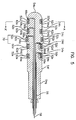
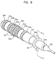
- FIG.1 is a perspective view of a first embodiment of an electrode for insertion into a body cavity in accordance with the present invention.
- the main body 54a, 54b, 54c, 54d, 54e, 54f, 54g, 54h, 54i, 54j consisting of electrically non-conductive material is rod-shaped overall.
- the front portion 54a of the rod-shaped main body is dome-shaped for easy insertion into the vagina.
- there is a projecting part 70 in the middle of the rod-shaped main body which is larger in diameter than the rest of the main body, preventing dislocation of the electrode.
- This projecting part 70 while the electrode is inserted in the vagina, prevents the electrode from being dislocated or slipping out by a mechanical impact of the patient's activity or an external cause.
- ring-shaped conductive bands 52a, 52b, 52c, 52d, 52e are formed on the rod-shaped main body.
- the number of ring-shaped conductive bands 52a, 52b, 52c, 52d and 52e is 5, at least two conductive bands can be formed.
- ring-shaped conductive bands In case of five ring-shaped conductive bands being formed, one of them is used for supplying a ground potential, the others in pairs used either for applying appropriate electrical stimulation signals for urinary incontinence treatment or for detecting EMG signals. At this time, the ring-shaped conductive band 52c on the above-mentioned missing preventive projecting part 70 can be used as such a ground potential node.
- the ring-shaped conductive bands 52a, 52b, 52c, 52d, 52e be larger in diameter than the adjacent non-conductive regions.
- the ring-shaped conductive bands 52a, 52b, 52c, 52d, 52e can be projected by 01-0.3mm in comparison with the adjacent non-conductive regions. This is in order to prevent the non-conductive materials from covering the conductive bands during the molding process.
- the rear part 54h, 54i, 54j of the main body is increasing in diameter. This is for placing an electrical line protector 92 described below with reference to FIG.8, and is also formed by a molding process.
- the step-down between the portions 54f and 54g of the main body also helps insertion with ease and comfort.
- the electrode shown in the drawing being a vaginal electrode
- the diameter and the length of the electrode might vary depending on demography.
- the width of the above-mentioned ring-shaped conductive bands may desirably range from 3 to 15mm, and the bands may be disposed apart from each other by 2-20mm.
- the non-conductive parts 54a, 54b, 54c, 54d, 54e, 54f, 54g, 54h, 54i, 54j of the main body might be made of solid materials such as plastic, nylon resin or the like. In this case, due to its solidity, an advantage lies in that the main body can firmly support the ring-shaped conductive bands mechanically.
- the non-conductive parts 54a, 54b, 54c, 54d, 54e, 54f, 54g, 54h, 54i and 54j are made of non-conductive silicon and the conductive bands 52a, 52b, 52c, 52d and 52e are made of conductive silicon.
- the conductivity of the conductive silicon should be similar to that of muscles which is 5-10 ⁇ .cm to prevent the current from being concentrated on a certain area, which might be painful to the patient.
- Such conductive silicon may be manufactured by adding carbon to silicon or may be purchased as a product sold under the name of Rc-1516 by Rhone-Poulenc Company.
- the conductive parts 52a, 52b, 52c, 52d, 52e are made of conductive silicon, its conductivity is remarkably lower than metallic materials. Thus it is desirable to use current-driven amplifier so that the input resistance of the instrumentation amplifier is more than a couple of hundred M ⁇ .cm for electrical stimulation and EMG biofeedback measurement.
- the solidity of the electrode may be 30-80 Shore A.
- the main body are not formed separately by parts, but formed as one unit by a molding process.
- an advantage lies in that the unit is highly waterproof while being washed.
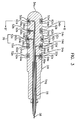
- FIG.2 is a perspective view of a second embodiment of an electrode for insertion into a body cavity.
- the same parts with those of FIG.1 have the same reference numerals and the description thereof will be omitted.
- the electrode for insertion into a body cavity shown in FIG.2, different from FIG.1, does not have a projecting part 70 in the middle of the main body.
- the ring-shaped conductive bands shown in FIGs.1 and 2 are electrically coupled to an external controller 100. Electrical stimulation is applied to the muscle under the control of the external controller and/or EMG signals captured from the muscle are delivered to the controller 100.
- FIG.2 the structure of the electrical connection between the ring-shaped conductive bands and the controller 100 is described in conjunction with the FIGs.3 to 5.
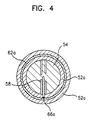
- FIG.3 is a sectional view of a first embodiment of the electrode taken along line A-A' of FIG.1; and FIG.4 is a sectional view of the electrode shown in FIG.3 taken along line B-B'.
- FIGs.3 and 4 the same parts with those of FIG.1 have the same reference numerals and the description thereof will be omitted.
- a plurality of ring-shaped metal bands 62a, 62b, 62c, 62d, 62e are embedded inside the ring-shaped conductive bands 52a, 52b, 52c, 52d, 52e, respectively.
- the ring-shaped metal bands 62a, 62b, 62c, 62d, 62e are embedded by the ring-shaped conductive bands 52a, 52b, 52c, 52d, 52e, respectively.
- These ring-shaped metal bands 62a, 62b, 62c, 62d, 62e are connected to electrical lines 58 by solders 661, 66b, 66c, 66d, 66e.
- Five electrical lines 58 are covered by a wiring cable 56 and are extended through the rear side of the main body to the outside so as to be coupled to the controller.
- the reference numerals 64a, 64b, 64c, 64d, 64e show that the ring-shaped conductive bands 52a, 52b, 52c, 52d, 52e are projecting compared to the adjacent main body parts 54a, 54b, 54c, 54d, 54e, 54f.
- FIG.5 is a sectional view of a second embodiment of the electrode taken along line A-A' of FIG.1. Only the inner and outer circumferences of the ring-shaped metal bands 62a, 62b, 62c, 62d, 62e are covered by the ring-shaped conductive bands 52a, 52b, 52c, 52d, 52e. Such a structure has an advantage in that soldering of the electrical lines to the metal bands is accomplished easily.
- the ring-shaped metal bands 62a, 62b, 62c, 62d, 62e are molded and embedded in the ring-shaped conductive bands 52a, 52b, 52c, 52d, 52e, thus the coherence of the two is excellent. Therefore, the connections between the ring-shaped conductive bands and the ring-shaped metal bands can not be separated even by a mechanical impact of the patient's activity or an external cause.
- the main body 54a, 54b, 54c, 54d, 54e, 54f, 54g, 54h, 54I, 54j of the electrode for insertion into a body cavity according to the present invention is formed as one unit with non-conductive materials such as non-conductive silicon. Namely, inside the ring-shaped conductive bands are filled with the non-conductive materials.
- This structure of the body can be formed by a silicon molding process and thus the coherence of the main body and the ring-shaped conductive bands 52a, 52b, 52c, 52d, 52e is excellent and the manufacturing process becomes very easy.
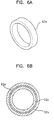
- FIGs.6A to 6C are diagrams of an exemplary manufacturing method of the electrode for insertion into a body cavity.
- pluralities of ring-shaped metal band 62a are formed. It is desirable that the width of the ring-shaped metal band 62a be the slightly smaller than that of the ring-shaped conductive silicon band 52a. Also the diameter of the ring-shaped metal band 62c placed in the projecting part 70 is desirably a little larger than the diameter of the rest of the metal bands.
- ring-shaped conductive bands are molded on the interior and exterior circumferences of the metal bands using conductive materials such as conductive silicon, as shown in FIG.6B. Then the ring-shaped metal bands inside the plurality of ring-shaped conductive bands 52a, 52b, 52c, 52d, and 52e are connected by soldering to the corresponding electrical line 58.
- the ring-shaped conductive bands 52a, 52b, 52c, 52d, 52e are disposed apart from each other in the longitudinal direction of the rod-shaped main body matrix and the electrical lines are also disposed such that one end thereof, which is to be coupled to the controller, is extended through the rear part of the rod-shaped matrix to the outside.
- the main body is molded in a rod-shaped matrix 80 using non-conductive silicon for example.
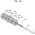
- FIGs.7A to 7D are drawings for illustrating another manufacturing method of the electrode for insertion into a body cavity according to another embodiment of the present invention.
- the ring-shaped metal bands 62a, 62b, 62c, 62d, 62e and ring-shaped conductive bands 52a, 52b, 52c, 52d, 52e surrounding the ring-shaped metal bands are sequentially formed as the same method described in FIGs.6A to 6B.
- the ring-shaped metal bands 62a, 62b, 62c, 62d, 62e are connected the corresponding electrical lines inside the cable 56 by soldering as seen in FIG.7A.
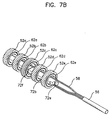
- a first and a second supporting members 72a and 72b are made by a molding process.
- the first supporting member 72a and the second supporting member 72b should be made of non-conductive materials, for example non-conductive silicon or plastic, and may be preferably formed using the same materials as the non-conductive materials forming the main body.
- the second supporting member 72b has a projecting part 72f corresponding to the ring-shaped conductive band 52c.
- the first supporting member 72a and the second supporting member 72b have the structures 72d, 72e suitable to fit into each other, for example the joint structure between prominence and depression. Namely, the first supporting member 72a has a T-shaped depression 72d sticking in and the second supporting member 72b has a T-shaped prominence part 72e sticking out. Other structures that will fix the two parts in place might be applied.
- the first supporting member 72a has a cylindrical sleeve through which the electrical cable including multiple electrical lines passes and an opening 72c that guides the electrical lines to the outside of the supporting member.
- the second supporting member 72b is placed inside the ring-shaped conductive bands enclosing the ring-shaped metal bands connected to the wires, while the ring-shaped conductive bands are arranged apart from each other by a predetermined distance.
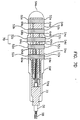
- the electrical cable passes through the sleeve.
- the first and the second supporting members 72a and 72b are put together then the electrical cable is fastened.
- the fixed parts up to the above step are mounted in the cylindrical matrix as shown in FIG.7D, and non-conductive materials such as non-conductive silicon is filled and molded in between the ring-shaped conductive bands 52a, 52b, 52c, 52d, 52e.
- non-conductive materials such as non-conductive silicon is filled and molded in between the ring-shaped conductive bands 52a, 52b, 52c, 52d, 52e.
- the supporting members 72a and 72b are merged into the main body.
- the supporting members to manufacture electrodes for insertion into a body cavity is not only convenient but also effective in reducing the manufacturing of defective products.
- the first and second supporting members can be manufactured by molding, which is very inexpensive. In result, it reduces the manufacturing time and costs of electrodes. Compared to the existing methods, the manufacturing method of the present invention can reduce the manufacturing costs by 90%.
- an electrode for insertion into a body cavity with three or more supporting members.
- FIG.8 is a perspective view of a third embodiment of an electrode for insertion into a body cavity.
- the electrode for insertion into a body cavity of the present invention is supplied with an insertion-depth control member 90 and electrical line protector 92.
- the insertion-depth control member 90 is used together with the main body and can be made of materials of a high frictional resistance against the materials constituting the main body, such as plastic. And the frictional resistance should be just enough so that the insertion-depth control member can be moved along the length of the electrode by hand before being inserted into the patient's body cavity.
- the insertion-depth control member while the electrode is being inserted into a body cavity, stays outside the body cavity.
- the electrical line protector 92 is attached to the sleeve of the rear side of the electrode for insertion into a body cavity, and should be made of materials that is firmer than the materials constituting the main body.
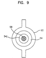
- FIG.9 is a sectional view of the electrode taken along line C-C' of FIG.8, and the inner diameter of the insertion depth control member 90 should be substantially the same as the outer diameter of the main body.
- the electrode for insertion into a body cavity described so far can be utilized not only for treatment for urinary incontinence, but also treatment for constipation, fecal incontinence, and for low-frequency physical therapy, EMG signal measurement, muscle stimulation treatment and bladder impedance measurement.
- the electrode for insertion into a body cavity of the present invention can be manufactured very easily and cost-effectively, and very comfortable to insert if made of silicon.
- the insertion-depth control member 90 has an advantage in that it can control the depth of insertion according to the length of the body cavity of the patient.
Landscapes
- Health & Medical Sciences (AREA)
- Cardiology (AREA)
- Heart & Thoracic Surgery (AREA)
- Engineering & Computer Science (AREA)
- Biomedical Technology (AREA)
- Nuclear Medicine, Radiotherapy & Molecular Imaging (AREA)
- Radiology & Medical Imaging (AREA)
- Life Sciences & Earth Sciences (AREA)
- Animal Behavior & Ethology (AREA)
- General Health & Medical Sciences (AREA)
- Public Health (AREA)
- Veterinary Medicine (AREA)
- Electrotherapy Devices (AREA)
Applications Claiming Priority (6)
| Application Number | Priority Date | Filing Date | Title |
|---|---|---|---|
| KR19980005997 | 1998-02-25 | ||
| KR9805997 | 1998-02-25 | ||
| KR5909798 | 1998-02-25 | ||
| KR1019980027301A KR100357435B1 (ko) | 1998-02-25 | 1998-07-07 | 질병치료를위한체강삽입용전극및그의제조방법 |
| KR9827301 | 1998-07-07 | ||
| KR2730198 | 1998-07-07 |
Publications (2)
| Publication Number | Publication Date |
|---|---|
| EP0938910A2 true EP0938910A2 (de) | 1999-09-01 |
| EP0938910A3 EP0938910A3 (de) | 2000-06-14 |
Family
ID=26633470
Family Applications (1)
| Application Number | Title | Priority Date | Filing Date |
|---|---|---|---|
| EP99301407A Withdrawn EP0938910A3 (de) | 1998-02-25 | 1999-02-25 | Scheidenelektrode zur Behandlung von Harninkontinenz |
Country Status (1)
| Country | Link |
|---|---|
| EP (1) | EP0938910A3 (de) |
Cited By (7)
| Publication number | Priority date | Publication date | Assignee | Title |
|---|---|---|---|---|
| FR2806634A1 (fr) | 2000-03-22 | 2001-09-28 | Emc Thiers | Sonde endocavitaire vaginale ou anale pour traitement par electrotherapie |
| EP1279413A1 (de) | 2001-07-27 | 2003-01-29 | Electroformage Medical Concept Thiers | Elastisch deformierbare Sonde zur Rehabilitation von Perineal- und Sphinktermuskeln |
| RU2278698C1 (ru) * | 2004-11-25 | 2006-06-27 | Александр Александрович Карасев | Ректально-вагинальное электродное устройство |
| EP2711047A1 (de) * | 2012-09-21 | 2014-03-26 | Beacmed S.r.L. | Dammsonde mit Elektroden und mit einem deformierbaren Verbindungselement |
| TWI458511B (de) * | 2012-04-10 | 2014-11-01 | ||
| CN106994091A (zh) * | 2017-03-31 | 2017-08-01 | 厦门尼金自动化设备有限公司 | 一种用于人体理疗和康复的理疗仪 |
| US11896823B2 (en) | 2017-04-04 | 2024-02-13 | Btl Healthcare Technologies A.S. | Method and device for pelvic floor tissue treatment |
Citations (1)
| Publication number | Priority date | Publication date | Assignee | Title |
|---|---|---|---|---|
| US5199443A (en) | 1991-03-26 | 1993-04-06 | Empi, Inc. | Incontinence electrode apparatus |
Family Cites Families (4)
| Publication number | Priority date | Publication date | Assignee | Title |
|---|---|---|---|---|
| GB1480103A (en) * | 1974-01-24 | 1977-07-20 | Garbe D | Incontinence control |
| US4909263A (en) * | 1988-10-28 | 1990-03-20 | C. R. Bard, Inc. | Method and apparatus for fitting a patient with a body cavity electrode |
| US5046511A (en) * | 1989-11-28 | 1991-09-10 | Empi, Inc. | Vaginal electrode with snap-on electrode pad and method for preparing electrode for use |
| US5456709A (en) * | 1994-03-16 | 1995-10-10 | Myo Kinetic Systems, Inc. | Interlocking electrode carrying body cavity insert for treating medical conditions |
-
1999
- 1999-02-25 EP EP99301407A patent/EP0938910A3/de not_active Withdrawn
Patent Citations (1)
| Publication number | Priority date | Publication date | Assignee | Title |
|---|---|---|---|---|
| US5199443A (en) | 1991-03-26 | 1993-04-06 | Empi, Inc. | Incontinence electrode apparatus |
Cited By (10)
| Publication number | Priority date | Publication date | Assignee | Title |
|---|---|---|---|---|
| FR2806634A1 (fr) | 2000-03-22 | 2001-09-28 | Emc Thiers | Sonde endocavitaire vaginale ou anale pour traitement par electrotherapie |
| EP1279413A1 (de) | 2001-07-27 | 2003-01-29 | Electroformage Medical Concept Thiers | Elastisch deformierbare Sonde zur Rehabilitation von Perineal- und Sphinktermuskeln |
| FR2827779A1 (fr) | 2001-07-27 | 2003-01-31 | Emc Thiers | Sonde de reeducation perineo-sphincterienne a deformation elastique |
| RU2278698C1 (ru) * | 2004-11-25 | 2006-06-27 | Александр Александрович Карасев | Ректально-вагинальное электродное устройство |
| TWI458511B (de) * | 2012-04-10 | 2014-11-01 | ||
| EP2711047A1 (de) * | 2012-09-21 | 2014-03-26 | Beacmed S.r.L. | Dammsonde mit Elektroden und mit einem deformierbaren Verbindungselement |
| US9101280B2 (en) | 2012-09-21 | 2015-08-11 | BEACMED S.r.L. | Perineal probe and process for making a perineal probe |
| CN106994091A (zh) * | 2017-03-31 | 2017-08-01 | 厦门尼金自动化设备有限公司 | 一种用于人体理疗和康复的理疗仪 |
| US11896823B2 (en) | 2017-04-04 | 2024-02-13 | Btl Healthcare Technologies A.S. | Method and device for pelvic floor tissue treatment |
| US12465762B2 (en) | 2017-04-04 | 2025-11-11 | Btl Healthcare Technologies A.S. | Method and device for pelvic floor tissue treatment |
Also Published As
| Publication number | Publication date |
|---|---|
| EP0938910A3 (de) | 2000-06-14 |
Similar Documents
| Publication | Publication Date | Title |
|---|---|---|
| US6185465B1 (en) | Vaginal electrode for urinary incontinence treatment | |
| US5800501A (en) | Intravaginal or intrarectal electrode | |
| US5370671A (en) | Incontinence electrode apparatus | |
| US6086549A (en) | Apparatus and method for treating female urinary incontinence | |
| US5667615A (en) | Method of making an incontinence electrode | |
| EP1318853B1 (de) | Sonde zur behandlung von inkontinenz | |
| US5649976A (en) | Neuromuscular stimulator electrode | |
| US6625495B1 (en) | Body-cavity probe with body conformable member | |
| US4909263A (en) | Method and apparatus for fitting a patient with a body cavity electrode | |
| US6432037B1 (en) | Intravaginal device for electrically stimulating and/or for sensing electrical activity of muscles and/or nerves defining and surrounding the intravaginal cavity | |
| EP0598459A2 (de) | Elektrode zur Reizung und/oder Feststellung der Muskelaktivität von durch eine Körperöffnung eines Patienten erreichbaren Muskels oder Muskelgruppen | |
| KR20200100774A (ko) | 신경의 전기 자극 시스템 | |
| EP0938910A2 (de) | Scheidenelektrode zur Behandlung von Harninkontinenz | |
| AU6485498A (en) | Tampon, in particular for women suffering from urinary incontinence | |
| WO2003105948A1 (en) | Female underpants structure provided with means to augment perineal muscles | |
| KR100674042B1 (ko) | 압력 센서를 구비하는 요실금 치료장치 | |
| KR100357435B1 (ko) | 질병치료를위한체강삽입용전극및그의제조방법 | |
| GB2284991A (en) | Intravaginal or intrarectal electrode | |
| KR20020000231A (ko) | 체강 삽입용 전극 | |
| EP1313529A2 (de) | Körperhohlensonde und verfahren | |
| KR102858860B1 (ko) | 골반저근 자극을 위한 전기자극 장치 | |
| ITPV940009A1 (it) | Sonda vaginale/anale per la terapia dell'incontinenza mediante elettrostimolazione e/o biofeedback pressorio o elettromiografico |
Legal Events
| Date | Code | Title | Description |
|---|---|---|---|
| PUAI | Public reference made under article 153(3) epc to a published international application that has entered the european phase |
Free format text: ORIGINAL CODE: 0009012 |
|
| AK | Designated contracting states |
Kind code of ref document: A2 Designated state(s): DE FR GB |
|
| AX | Request for extension of the european patent |
Free format text: AL;LT;LV;MK;RO;SI |
|
| PUAL | Search report despatched |
Free format text: ORIGINAL CODE: 0009013 |
|
| AK | Designated contracting states |
Kind code of ref document: A3 Designated state(s): AT BE CH CY DE DK ES FI FR GB GR IE IT LI LU MC NL PT SE |
|
| AX | Request for extension of the european patent |
Free format text: AL;LT;LV;MK;RO;SI |
|
| 17P | Request for examination filed |
Effective date: 20001027 |
|
| AKX | Designation fees paid |
Free format text: DE FR GB |
|
| 17Q | First examination report despatched |
Effective date: 20031020 |
|
| GRAP | Despatch of communication of intention to grant a patent |
Free format text: ORIGINAL CODE: EPIDOSNIGR1 |
|
| STAA | Information on the status of an ep patent application or granted ep patent |
Free format text: STATUS: THE APPLICATION IS DEEMED TO BE WITHDRAWN |
|
| 18D | Application deemed to be withdrawn |
Effective date: 20051202 |