EP0938432B1 - Capuchon de fermeture - Google Patents
Capuchon de fermeture Download PDFInfo
- Publication number
- EP0938432B1 EP0938432B1 EP97944669A EP97944669A EP0938432B1 EP 0938432 B1 EP0938432 B1 EP 0938432B1 EP 97944669 A EP97944669 A EP 97944669A EP 97944669 A EP97944669 A EP 97944669A EP 0938432 B1 EP0938432 B1 EP 0938432B1
- Authority
- EP
- European Patent Office
- Prior art keywords
- cover
- outer skirt
- skirt
- container
- hinge
- Prior art date
- Legal status (The legal status is an assumption and is not a legal conclusion. Google has not performed a legal analysis and makes no representation as to the accuracy of the status listed.)
- Expired - Lifetime
Links
Images


Classifications
-
- B—PERFORMING OPERATIONS; TRANSPORTING
- B65—CONVEYING; PACKING; STORING; HANDLING THIN OR FILAMENTARY MATERIAL
- B65D—CONTAINERS FOR STORAGE OR TRANSPORT OF ARTICLES OR MATERIALS, e.g. BAGS, BARRELS, BOTTLES, BOXES, CANS, CARTONS, CRATES, DRUMS, JARS, TANKS, HOPPERS, FORWARDING CONTAINERS; ACCESSORIES, CLOSURES, OR FITTINGS THEREFOR; PACKAGING ELEMENTS; PACKAGES
- B65D47/00—Closures with filling and discharging, or with discharging, devices
- B65D47/04—Closures with discharging devices other than pumps
- B65D47/06—Closures with discharging devices other than pumps with pouring spouts or tubes; with discharge nozzles or passages
- B65D47/08—Closures with discharging devices other than pumps with pouring spouts or tubes; with discharge nozzles or passages having articulated or hinged closures
- B65D47/0804—Closures with discharging devices other than pumps with pouring spouts or tubes; with discharge nozzles or passages having articulated or hinged closures integrally formed with the base element provided with the spout or discharge passage
- B65D47/0833—Hinges without elastic bias
- B65D47/0838—Hinges without elastic bias located at an edge of the base element
-
- B—PERFORMING OPERATIONS; TRANSPORTING
- B65—CONVEYING; PACKING; STORING; HANDLING THIN OR FILAMENTARY MATERIAL
- B65D—CONTAINERS FOR STORAGE OR TRANSPORT OF ARTICLES OR MATERIALS, e.g. BAGS, BARRELS, BOTTLES, BOXES, CANS, CARTONS, CRATES, DRUMS, JARS, TANKS, HOPPERS, FORWARDING CONTAINERS; ACCESSORIES, CLOSURES, OR FITTINGS THEREFOR; PACKAGING ELEMENTS; PACKAGES
- B65D50/00—Closures with means for discouraging unauthorised opening or removal thereof, with or without indicating means, e.g. child-proof closures
- B65D50/02—Closures with means for discouraging unauthorised opening or removal thereof, with or without indicating means, e.g. child-proof closures openable or removable by the combination of plural actions
- B65D50/04—Closures with means for discouraging unauthorised opening or removal thereof, with or without indicating means, e.g. child-proof closures openable or removable by the combination of plural actions requiring the combination of simultaneous actions, e.g. depressing and turning, lifting and turning, maintaining a part and turning another one
- B65D50/045—Closures with means for discouraging unauthorised opening or removal thereof, with or without indicating means, e.g. child-proof closures openable or removable by the combination of plural actions requiring the combination of simultaneous actions, e.g. depressing and turning, lifting and turning, maintaining a part and turning another one where one action elastically deforms or deflects at least part of the closure, the container or an intermediate element, e.g. a ring
-
- B—PERFORMING OPERATIONS; TRANSPORTING
- B65—CONVEYING; PACKING; STORING; HANDLING THIN OR FILAMENTARY MATERIAL
- B65D—CONTAINERS FOR STORAGE OR TRANSPORT OF ARTICLES OR MATERIALS, e.g. BAGS, BARRELS, BOTTLES, BOXES, CANS, CARTONS, CRATES, DRUMS, JARS, TANKS, HOPPERS, FORWARDING CONTAINERS; ACCESSORIES, CLOSURES, OR FITTINGS THEREFOR; PACKAGING ELEMENTS; PACKAGES
- B65D2215/00—Child-proof means
- B65D2215/04—Child-proof means requiring the combination of different actions in succession
-
- B—PERFORMING OPERATIONS; TRANSPORTING
- B65—CONVEYING; PACKING; STORING; HANDLING THIN OR FILAMENTARY MATERIAL
- B65D—CONTAINERS FOR STORAGE OR TRANSPORT OF ARTICLES OR MATERIALS, e.g. BAGS, BARRELS, BOTTLES, BOXES, CANS, CARTONS, CRATES, DRUMS, JARS, TANKS, HOPPERS, FORWARDING CONTAINERS; ACCESSORIES, CLOSURES, OR FITTINGS THEREFOR; PACKAGING ELEMENTS; PACKAGES
- B65D2251/00—Details relating to container closures
- B65D2251/10—Details of hinged closures
- B65D2251/1016—Means for locking the closure in closed position
-
- B—PERFORMING OPERATIONS; TRANSPORTING
- B65—CONVEYING; PACKING; STORING; HANDLING THIN OR FILAMENTARY MATERIAL
- B65D—CONTAINERS FOR STORAGE OR TRANSPORT OF ARTICLES OR MATERIALS, e.g. BAGS, BARRELS, BOTTLES, BOXES, CANS, CARTONS, CRATES, DRUMS, JARS, TANKS, HOPPERS, FORWARDING CONTAINERS; ACCESSORIES, CLOSURES, OR FITTINGS THEREFOR; PACKAGING ELEMENTS; PACKAGES
- B65D2251/00—Details relating to container closures
- B65D2251/10—Details of hinged closures
- B65D2251/1066—Actuating means
Definitions
- the invention relates to a closure cap for sealing a container. More particularly the invention relates to a closure cap which is very easy to open by an adult.
- Closure caps are known, which are child resistant and comprise a skirt that must be manually squeezed in a given radial direction to permit unscrewing of it and removal from the container.
- closure caps which comprise a foldable top cover that can be snapped down in a closed position. To release the cover and open the container, one has to apply pressure on top of it to deform its edges and cause it to unsnap. Closures of this type are described, by way of examples, in U.S. patents Nos. 3,612,322 (see Figs. 18 to 20 of it); 3,934,745 (see Figs. 3 and 4 of it); 3,845,872 and 4,535,905.
- DE-A-3 625 477 discloses a closure cap according to the preamble of appended claim 1, having an inner skirt connectable to the neck of a container, an outer skirt extending externally over the inner skirt at a given distance from the same, and a cover that is attached to the outer skirt by a hinge.
- the inner and outer skirts are connected to each other via a peripheral transversal wall extending between their upper portions.
- Snap means are provided to releasably lock the cover in a closed position.
- the snap means comprise a pair of opposite fingers that are cut into the outer skirt and respectively positioned at an angle of 90° with respect to the hinge. When a pressure is applied onto the fingers, they bend radially inwardly and release the cover, which then must be folded up manually.
- US-A-5,573,127 discloses a cap having an inner skirt, an outer skirt extending externally over the inner skirt at a given distance from the same, and a cover that is attached to the outer skirt by a hinge.
- the inner and outer skirt are connected to each other via a peripheral transversal wall extending between their upper portions.
- Means are provided to push up the cover in open position. These means comprise a finger that is cut out in both the outer skirt and the peripheral transversal wall and is pivotably connected to the bottom portion of the inner skirt. When a pressure is applied onto this finger, it bends radially inwardly and its top end acts as a cam and pushes the cover up.
- the object of the present invention is to provide a closure cap which satisfies the above mentioned needs. This is achieved by the cap described in appended claim 1 and the combination of a cap and a container described in appended claim 14.
- the invention as broadly disclosed provides a closure cap for sealing a container having an opening surrounded by a neck.
- This cap comprises an inner skirt shaped and sized to fit externally onto the neck.
- This inner skirt has an upper portion and a lower portion.
- Attachment means are provided, which are integral to the inner skirt and devised in such a way as to cooperate with corresponding attachment means provided onto the neck for securing the inner skirt onto it , preferably in a non-removable manner.
- the cap also comprises an outer skirt projecting from the inner skirt.
- This outer skirt has an upper portion, a lower portion and an external surface. It is made of a material that is resiliently flexible and can be deformed when an external pressure is applied onto its external surface. It extends over the inner skirt at a given distance from the same, thereby defining a gap therebetween.
- the cap further comprises a cover shaped and sized to close the opening of the container.
- This cover has a peripheral edge attached to the outer skirt by a hinge and being foldable up and down about the hinge.
- Snap means are provided for releasably locking the cover in a closed position when it is folded down over the neck of the container.
- These snap means are located on the cap in an opposite position with respect to the hinge of the cover and have one part integral to the upper portion of the outer skirt and another part integral to the cover.
- the one part of the snap means that is integral to the upper portion of the outer skirt is positioned and devised to move and disengage the other part of the snap means, thus releasing the cover, when external pressure is applied at a suitable location onto the external surface of the lower portion of the outer skirt.
- the outer skirt may be connected either to the upper portion of the inner skirt or to the lower portion of said inner skirt.
- the invention as claimed is restricted to the first one of these two embodiments, viz. the one where the outer skirt has its upper portion connected to the upper portion of the inner skirt by a peripheral transversal wall that is made of the same resiliently flexible material.
- the one part of the snap means that is integral to the upper portion of the outer skirt extends above the peripheral transversal wall and projects towards the hinge in such a manner as to engage the other part of the snap means when the cover is in the closed position.
- the closure cap In use, the closure cap is attached to the neck of the container and the cover maintained by the snap means in a closed position to close the container opening. To release the cover, one has only to exert sufficient pressure onto a suitable location of the outer surface of the outer skirt.
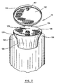
- the cap 10 according to the first embodiment of the invention as shown in Figs.1 to 6 is intended to be used for closing the opening of the container 60.
- the container 60 which is shown on Figs. 2 and 3 is of a conventional shape and comprises an opening surrounded by a neck portion 62.
- the cap 10 comprises an inner skirt 20 and an outer skirt 30.
- the inner skirt 20 has an upper portion and a lower portion and is shaped and sized to fit externally onto the neck 62.
- the inner skirt 20 is provided with attachment means which are integral to the inner skirt 20. These attachment means cooperate with corresponding attachment means provided onto the neck 62.
- non-removable attachment means may consist of one or more peripheral beads 22 or of a succession of small bumps, provided on the internal face of the inner skirt 20 and on the external face of the neck portion 62 in such a manner as to shape within each other.
- Removable attachment means may consist of a screwing device.
- the outer skirt 30 is preferably tubular in shape.
- the outer skirt 30 could be of another shape.
- the outer skirt 30 could comprise two flat surfaces on which pressure would be applied.
- This outer skirt 30 is connected to and projects from the upper portion of the inner skirt 20.
- the outer skirt 30 extends over the inner skirt 20 at a given distance from the same, thereby defining a gap 24 between the same and the neck portion 62 of the container 60.
- the outer skirt 30 is connected to the upper portion of the inner skirt 20 by a peripheral transversal wall 27.
- This wall 27 propagates the force induced by a pressure which may be applied on the outer skirt 30.
- Some portions 26 of the wall 27 may advantageously be cut-out. Such cut-out portions 26 are located respectively at substantially the same distance from both the hinge 54 and the snap means 31 as will be better described hereinafter.
- the cap 10 also comprises a cover 50 shaped and sized to close the opening of the container 60.
- the cover 50 has a peripheral edge 52 that is attached to the outer skirt 30 by a hinge 54 (shown in Fig.4).
- the cover 50 is foldable up and down about this hinge 54.
- the inner skirt 20 is provided with a partition element 28 which projects inwardly and partly obturates the container opening.
- the partition element 28 may extend the peripheral transversal wall 27 and comprises an orifice 29 which is advantageously sized and shaped according to the texture of the product (i.e. solid, liquid, colloidal, etc..) with which the container 60 is filled up, in order to permit good outflow of this product when one uses the container 60.
- the cover 50 has its inner surface provided with a sealing ring 58 shaped and sized to seal the periphery of the orifice 29 of the opening of the partition element 28 when the cover is in a closed position.
- the cover 50 and/or the partition element 28 may also be provided with any sealing devices, such as a sealing ring. This is well known in the art and need not be further described.
- the cover 50 When the cover 50 is folded down over the neck portion 62 of the container 60, it is releasably locked in a closed position (shown in Figs. 2, 3 or 4) by snap means 31 of a conventional structure.
- the snap means 31 and the hinge 54 are located in radially opposite positions.
- the snap means 31 has one part 32 integral to the upper portion of the outer skirt 30 and another part 56 integral to the cover 50, respectively.
- the outer skirt 30 is made of a material, preferably a plastic material, that is resiliently flexible and can be deformed when an external pressure is applied onto its external surface.
- the part 32 of the snap means 31 that is integral to the upper portion of the outer skirt 30 is positioned and devised to move and disengage the other part 56 of the snap means 31, thus releasing the cover 50, when external pressure is applied at a suitable location onto the external surface of the lower portion of the outer skirt 30.
- Marking means may be provided onto the external surface of the outer skirt 30 underneath the snap means 31 in order to mark the position of the suitable location where the external pressure must be applied to release the cover 50.
- These marking means may consist of grooves 36 made into the outer surface of the outer skirt 30. They may also consist of a change in the texture of the outer surface of the outer skirt 30 which would be noticeable when one would touch the latter, even in the dark. Alternatively they may consist of a depression or a simple coloured spot.
- a part of the outer skirt 30 can project upwardly and thus overlay at least partially the peripheral edge 52 of the cover 50 so that the joint between the cover 50 and the outer skirt 30 is not accessible.
- Such a design is desirable as it may prevent grasping of the cover 50 by a child to force the container to open.
- the line defining the joint between the cover 50 and the outer skirt 30 may be of any design.
- the closure cap 10 is snapped or otherwise secured onto the neck of the container 60 and the cover 50 is maintained by the snap means 31 in a close position.
- the cover 50 To release the cover 50, one has only to exert sufficient pressure onto the suitable location that is marked on the outer surface of the outer skirt 30 and below the hinge. As illustrated in Fig. 3 this suitable location is underneath the snap means 32. Deformation of the inner skirt 30 as a result of the pressure exerted by the user is made possible thanks to the gap 24 between the outer skirt 30 and the inner skirt 20 and/or the external surface of the neck portion 62 of the container 60.
- To close the cover 50 one needs only to fold it down over the neck 62 of the container 60 and engage the two part 32 and 56 of the snap means by applying sufficient pressure on top of the cover 50.
- the slotted portions 26 in the transversal wall 27, if any, facilitate the deformation of the outer skirt 30.
- a short description or logo explaining how to use the cap can be printed or stamped on it at a suitable location.
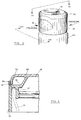
- Figs. 5 and 6 emphasize in a schematic manner the radial and vertical deformations of the outer skirt 30 when the same is pressed. Such deformations causes the snap part 32 to swivel outwardly and to disengage from the corresponding snap part 56 of the cover 50. In the meantime, the cover 50 is pushed up to open and pivot about its hinge 54 by the vertical deformation of the cap shown in Fig. 6.
- the latter could have portions of reduced thickness. Such portions should be provided peripherally and substantially at the same distance from both the hinge 54 and the snap means 31.
- the cap 110 according to the second embodiment of the invention as shown in Fig. 7 is similar to the one shown in Figs. 1 to 6, except that, in order to facilitate deformation of its outer skirt 130, the latter has, instead of portions of a reduced thickness, slotted portions 136 provided peripherally and substantially at the same distance from both the hinge 154 and the snap means 131.
- the peripheral edge 152 of the cover 150 and the upper portion of the outer skirt 130 are also preferably shaped so as to define together a smooth external surface when the cover is locked in a closed position, thereby improving the safety of the cap 110 by preventing grasping of the cover 150 by a child to force the container to open.
- the cap further comprises a pin 151 provided on the internal surface of the cover 150 to seal the orifice 129,
- This pin 151 is shaped and sized to fit within the orifice 129 provided on the partition element 128 of the cap 110. This is particularly efficient to seal the orifice 129 when this orifice is of a small diameter, like the one illustrated in Fig.7.
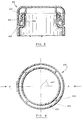
- the cap 310 shown in Fig. 8 is also similar to the caps shown in Figs. 1 to 7, except that the lower portion of its outer skirt 330 is connected to and projects upwardly from the lower portion of its inner skirt 320. This embodiment is excluded from the scope of the claims on file. Once again, provided that there is a sufficient gap 324 between the inner skirt 220 and the outer skirt 330, disengagement of the snap means 331 and thus release of the cover 350 is achieved if sufficient pressure (shown in dotted lines) is applied onto the outer skirt 330.
- the cap 310 according to the third embodiment of the invention as shown in Fig. 9 is similar to the caps shown in Figs. 1 to 7 except that it further comprises radial reinforcement ribs 340 between the inner skirt 320 and the other skirt 330. These ribs 340 are advantageously located along straight lines extending at an optimal angle of about 45° with respect to an axis AA extending between the hinge 354 and the snap means (not shown).
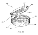
- the cap 410 according to the fourth embodiment of the invention as shown in Fig. 10 is similar to the caps shown in Figs. 1 to 9 except that the snap means comprises at least two distinct sets of elements. Each set has one part 432' or 432" integral to the upper portion of the outer skirt 430 and another part 456' or 456" integral to the cover 450. These two distinct sets are peripherally spaced apart from each other. These two distinct sets and the hinge 454 are located in substantially opposite positions.
- a depression 436 is provided into the external surface of the outer skirt 430 to mark the position of the suitable location where the external pressure must be applied to release the cover 450. As is shown, this depression 436 is positioned between the two distinct sets of elements.
- the closure cap 510 according to the fifth embodiment of the invention as shown in Fig. 11 is similar to the caps shown in Figs. 1 to 10 except that it is made integral to the container 560 itself.
- the container 560 is provided with a tubular wall 564, whose upper portion is integral to the inner skirt 520.
- the cap 510 is secured to the container 560 by the upper portion of the wall 564, the container 560 requires no more to be provided with any neck portion or attachment means to secure the closure cap 510 on it.
- This embodiment provides a one-piece container 560 having an efficient and easy-to-open closure system.
- the cap 510 may be advantageously provided with one or more of the previously described embodiments relating to the inner skirt 520; the outer skirt 530, the cap 550, the partition wall 528, the snaps means 531, etc.
- the upper portion of the container 560 defining the inner skirt 520 has to be made of the resilient material which has been described hereinabove for the manufacture of the closure caps shown in Figs. 1 to 10.
- closure caps described above may be moulded in one piece with any kind of plastic material. This is well known in the art and need not be further described.
Landscapes
- Engineering & Computer Science (AREA)
- Mechanical Engineering (AREA)
- Closures For Containers (AREA)
- Finger-Pressure Massage (AREA)
- Transmission Of Braking Force In Braking Systems (AREA)
- Glass Compositions (AREA)
Claims (14)
- Un capuchon (10, 110, 410) pour fermer un contenant (60) ayant une ouverture entourée d'un col, ledit capuchon comprenant:caractérisé en ce que:a) une jupe intérieure (20) façonnée et dimensionnée pour s'emboíter extérieurement sur le col, ladite jupe intérieure ayant une portion supérieure (22) et une portion inférieure;b) les moyens d'attache intégraux à la jupe intérieure, lesdits moyens d'attache coopérant avec des moyens d'attache correspondants prévus sur le col pour fixer la jupe intérieure à même ledit col;c) une jupe extérieure (30, 130, 430) ayant une portion supérieure, une portion inférieure et une surface externe, ladite jupe extérieure s'étendant sur la jupe intérieure à une distance donnée de celle-ci pour former avec elle un espace (24), ladite jupe extérieure étant d'une épaisseur donnée et ayant sa portion supérieure connectée à la portion supérieure de la jupe inférieure par une paroi transversale périphérique (27);d) un couvercle (50, 150, 450) façonné et dimensionné pour fermer l'ouverture du contenant, ledit couvercle ayant une arête périphérique (52) attachée à la jupe extérieure par une charnière (54) et étant pliable vers le haut et vers le bas par rapport à ladite charnière au-dessus de la paroi périphérique; ete) des moyens de fermeture (31, 131) ayant une première partie (32) intégrale à la portion supérieure de la jupe extérieure et une autre partie (56) intégrale au couvercle, pour fixer de façon réversible le couvercle dans une position fermée lorsqu'il est plié vers le bas sur le col du contenant;la jupe extérieure (30, 130, 430) et la paroi périphérique (27) sont faites d'un matériau qui est flexible et résilient et peut être déformé lorsqu'une pression externe est appliquée sur la surface externe de ladite jupe extérieure;les moyens de fermeture (31, 131) sont localisés sur le capuchon à un endroit opposé à la charnière (54) sur le couvercle; etla première partie (32) des moyens de fermeture qui est intégrale à la portion supérieure de la jupe externe (30) s'étend au-dessus de la paroi transversale périphérique (27) en direction de la charnière (54) de façon à engager l'autre partie (56) des moyens de fermeture lorsque le couvercle est dans sa position fermée;de sorte que lorsque la pression externe est appliquée sur la surface externe de la jupe extérieure (30, 130, 430) en dessous desdits moyens de fermeture (31, 131), ladite jupe extérieure est déformée à la fois latéralement et verticalement et amène la première partie (32) des moyens de fermeture à se déformer vers l'extérieur, à désengager l'autre partie (56) des moyens de fermeture et à ainsi libérer le couvercle (50, 150, 450) tout en poussant simultanément ledit couvercle vers le haut pour l'ouvrir et le pivoter autour de la charnière (54).
- Le capuchon selon la revendication 1, caractérisé en ce que la jupe extérieure est de forme tubulaire.
- Le capuchon selon la revendication 2, caractérisé en ce qu'il comprend en outre des moyens (36) disposés sur la surface externe de la jupe extérieure (30) en dessous des moyens de fermeture (31) et de la charnière (54) de façon à marquer deux endroits opposés où la pression externe doit être appliquée pour relâcher le couvercle (50).
- Le capuchon selon la revendication 2, caractérisé en ce que les moyens de fermeture comprennent au moins deux jeux distincts d'éléments (432', 432") qui sont espacés périphériquement et en ce que ledit capuchon (410) comprend en outre des moyens (436) disposés sur la surface extérieure de la jupe extérieure entre les deux jeux distincts d'éléments de façon à marquer la position de l'endroit adéquat où la pression extérieure pour relâcher le couvercle (450) doit être appliquée.
- Le capuchon selon l'une quelconque des revendications 1 à 4, caractérisé en ce que l'arête périphérique (52) du couvercle (50) et la portion supérieure de la jupe extérieure (30) sont façonnés pour définir ensemble une surface externe lisse quand le couvercle (50) est fixé en position fermée, ceci évitant la prise ou le saisissement du couvercle en vue de l'ouvrir de force.
- Le capuchon selon l'une quelconque des revendications 1 à 4, caractérisé en ce que l'arête périphérique (52) du couvercle dans sa position fermée et la jupe extérieure (30) définissant ensemble un joint et en ce que la portion supérieure de la jupe extérieure (30) s'étend verticalement pour recouvrir ledit joint.
- Le capuchon selon l'une quelconque des revendications 1 à 6, caractérisé en ce que des portions (26) de la paroi transversale périphérique (27) sont coupées, lesdites portions (26) étant disposées substantiellement à la même distance à la fois de la charnière et des moyens de fermeture.
- Le capuchon selon l'une quelconque des revendications 1 à 7, caractérisé en ce que la jupe extérieure (130) a des portions coupées (136) pour faciliter la déformation de ladite jupe extérieure, ces portions coupées étant disposées périphériquement et sensiblement à la même distance à la fois de la charnière (154) et des moyens de fermeture (131).
- Le capuchon selon l'une quelconque des revendications 1 à 8, caractérisé en ce qu'il comprend en outre des nervures de renforcement radiales entre les jupes intérieure et extérieure, ces nervures étant disposées selon des lignes droites s'étendant à un angle d'environ 45° par rapport à un axe s'étendant entre la charnière et les moyens de fermeture.
- Le capuchon selon l'une quelconque des revendications 1 à 9, caractérisé en ce que des moyens d'attache (22) intégraux à la jupe intérieure (20, 320) sont constitués par un fermoir.
- Le capuchon selon l'une quelconques des revendications 1 à 10, caractérisé en ce que ledit capuchon est fait de plastique moulé.
- Le capuchon selon l'une quelconque des revendications 1 à 10, caractérisé en ce que le couvercle (50) a une surface interne pourvue d'un anneau de guidage et de scellage (58) dimensionné pour s'emboíter dans l'ouverture du contenant (60) lorsque le couvercle est dans une position fermée.
- Le capuchon selon la revendication 12, caractérisé en ce que la jupe extérieure est pourvue d'un élément de séparation (128) qui s'étend à l'intérieur et obstrue partiellement l'ouverture du contenant, ledit élément comprenant un orifice (129), et en ce que le couvercle (150) a une surface interne pourvue d'un dispositif de scellage (151) façonné et dimensionné pour sceller l'orifice de l'élément de séparation lorsque le couvercle est dans une position fermée.
- La combinaison d'un capuchon (510) avec un contenant ayant une ouverture, caractérisée en ce que ledit capuchon (510) comprend:a) une jupe intérieure (520) qui est intégrale au contenant dans une zone entourant l'ouverture, ladite jupe intérieure ayant une portion supérieure et une portion inférieure;b) une jupe extérieure (530) ayant une portion supérieure, une portion inférieure et une surface externe, ladite jupe extérieure s'étendant sur la jupe intérieure à une distance donnée de celle-ci pour former avec elle un espace, ladite jupe extérieure étant d'une épaisseur donnée et ayant sa portion supérieure connectée à la portion supérieure de la jupe intérieure par une paroi transversale périphérique;c) un couvercle (550) façonné et dimensionné pour fermer l'ouverture du contenant, ledit couvercle ayant une arête périphérique attachée à la jupe extérieure par une charnière et étant pliable vers le haut et vers le bas par rapport à ladite charnière au-dessus de la paroi périphérique; etd) des moyens de fermeture (531) ayant une première partie intégrale à la portion supérieure de la jupe extérieure et une autre partie intégrale au couvercle, pour fixer de façon réversible le couvercle dans une position fermée lorsqu'il est plié vers le bas sur le col du contenant,
dans lequel:de sorte que lorsque la pression externe est appliquée sur la surface externe de la jupe extérieure en dessous desdits moyens de fermeture, ladite jupe extérieure est déformée à la fois latéralement et verticalement et amène la première partie des moyens de fermeture à se déformer vers l'extérieur, à désengager l'autre partie des moyens de fermeture et à ainsi libérer le couvercle (550) tout en poussant simultanément ledit couvercle vers le haut pour l'ouvrir et le faire pivoter autour de la charnière.la jupe extérieure (530) et la paroi périphérique sont faites en un matériau qui est flexible et résilient et peut être déformé lorsqu'une pression externe est appliquée sur la surface externe de ladite jupe extérieure;la première partie des moyens de fermeture (531) qui est intégrale à la portion supérieure de la jupe extérieure s'étend au-dessus de la paroi transversale périphérique dans la direction de la charnière de façon à engager l'autre partie de moyen de fermeture lorsque le couvercle est dans la position fermée,
Applications Claiming Priority (3)
| Application Number | Priority Date | Filing Date | Title |
|---|---|---|---|
| CA2190172 | 1996-11-12 | ||
| CA002190172A CA2190172C (fr) | 1996-11-12 | 1996-11-12 | Bouchon |
| PCT/CA1997/000773 WO1998021113A1 (fr) | 1996-11-12 | 1997-10-17 | Capuchon de fermeture |
Publications (2)
| Publication Number | Publication Date |
|---|---|
| EP0938432A1 EP0938432A1 (fr) | 1999-09-01 |
| EP0938432B1 true EP0938432B1 (fr) | 2001-04-11 |
Family
ID=4159241
Family Applications (1)
| Application Number | Title | Priority Date | Filing Date |
|---|---|---|---|
| EP97944669A Expired - Lifetime EP0938432B1 (fr) | 1996-11-12 | 1997-10-17 | Capuchon de fermeture |
Country Status (10)
| Country | Link |
|---|---|
| US (1) | US5860543A (fr) |
| EP (1) | EP0938432B1 (fr) |
| JP (1) | JP4044144B2 (fr) |
| AT (1) | ATE200457T1 (fr) |
| AU (1) | AU725411B2 (fr) |
| BR (1) | BR9713016A (fr) |
| CA (1) | CA2190172C (fr) |
| DE (1) | DE69704567T2 (fr) |
| ES (1) | ES2156006T3 (fr) |
| WO (1) | WO1998021113A1 (fr) |
Families Citing this family (36)
| Publication number | Priority date | Publication date | Assignee | Title |
|---|---|---|---|---|
| AU2253201A (en) * | 1999-12-03 | 2001-06-12 | Sussex Technology, Inc. | Toggle action dispensing closure with locking means |
| US6439409B1 (en) * | 2001-01-03 | 2002-08-27 | Mark W. Dressel | Child-resistant and elder-friendly vial closure system |
| US6460712B2 (en) | 2001-02-02 | 2002-10-08 | Seaquist Closures Foreign, Inc. | One-piece tamper-evident closure system with a resealable, hinged lid |
| US6578744B2 (en) * | 2001-03-22 | 2003-06-17 | Crown Cork & Seal Technologies Corporation | Watertight tube closure |
| DE10121232C2 (de) * | 2001-04-30 | 2003-10-02 | Braun Gmbh E | Vorrichtung zum Verabreichen von Medikamenten |
| FR2824812B1 (fr) * | 2001-05-16 | 2003-09-19 | Oreal | Capsule de distribution avec ouverture securisee |
| US6866164B2 (en) * | 2002-04-26 | 2005-03-15 | Rexam Medical Packaging Inc. | Child resistant dispenser |
| US20020179644A1 (en) * | 2002-05-30 | 2002-12-05 | Evans Christopher T. | Toggle action dispensing closure with locking means |
| JP4416612B2 (ja) * | 2004-09-17 | 2010-02-17 | ダイキョーニシカワ株式会社 | キャップ |
| US8172101B2 (en) | 2004-07-13 | 2012-05-08 | Becton, Dickinson And Company | Flip top cap with contamination protection |
| US7717284B2 (en) * | 2004-07-27 | 2010-05-18 | Becton, Dickinson And Company | Flip top cap |
| US7451896B2 (en) * | 2004-10-27 | 2008-11-18 | Owens-Illinois Closure, Inc. | Child-resistant dispensing closure, package and method of manufacture |
| US7861881B2 (en) * | 2004-10-28 | 2011-01-04 | General Mills Cereals, Llc. | Removable overcap for microwaveable packaged good article |
| US7370773B2 (en) * | 2004-12-21 | 2008-05-13 | Mcneil-Ppc, Inc. | Child-resistant closure for dispensing containers |
| US20060191933A1 (en) * | 2005-02-25 | 2006-08-31 | Seaquist Closures Foreign, Inc. | Closure system with improved sealing of lid |
| US7823736B1 (en) * | 2005-03-30 | 2010-11-02 | Rexam Closure Systems Inc. | Plastic closure having mounting ring for containers |
| US20060219652A1 (en) * | 2005-03-30 | 2006-10-05 | Owens-Illinois Closure Inc. | Plastic closure for containers |
| US7546931B2 (en) * | 2005-07-08 | 2009-06-16 | Becton, Dickinson And Company | Flip top cap |
| US8308004B2 (en) * | 2005-11-22 | 2012-11-13 | Rexam Healthcare Packaging Inc. | Dispensing package having non-removable and non-rotatable dispensing closure |
| US7798348B2 (en) * | 2005-12-02 | 2010-09-21 | Berry Plastics Corporation | Child-resistant closure |
| US8074821B2 (en) * | 2006-03-15 | 2011-12-13 | Mcneil-Ppc, Inc. | Child-resistant container and container cap |
| US20070251909A1 (en) * | 2006-04-27 | 2007-11-01 | Gilles Decelles | Flip-top closure cap |
| ES2262450B1 (es) * | 2006-05-18 | 2007-09-16 | Seaplast, S.A. | "tapon con tapa abatible para botellas y similares dotado de un sistema automatico de apertura de la tapa que comprende un pulsador mejorado". |
| US20080083758A1 (en) * | 2006-06-12 | 2008-04-10 | Kraft Foods Holdings, Inc. | Push button flip top with attached second container |
| US20080245795A1 (en) * | 2007-04-05 | 2008-10-09 | Berge Gary L | Auto open closure |
| JP5437235B2 (ja) * | 2007-05-04 | 2014-03-12 | フレセニウス・メディカル・ケア・ドイチュラント・ゲーエムベーハー | 体外血液治療装置の血液治療ユニットを監視する方法及び装置 |
| TW200917824A (en) * | 2007-10-12 | 2009-04-16 | Univ Nat Taiwan | Shockproof method for digital imaging |
| US7918360B2 (en) | 2008-03-07 | 2011-04-05 | Silgan Plastics Corporation | Container with overcap |
| US8292110B2 (en) * | 2008-10-10 | 2012-10-23 | Gunn And Richards, Inc. | Container having dual-mode closure assembly |
| GB0922117D0 (en) | 2009-12-18 | 2010-02-03 | Obrist Closures Switzerland | A child-resistant closure |
| EP2588384B1 (fr) * | 2011-03-03 | 2014-05-14 | AptarGroup, Inc. | Fermeture comprenant un élément inviolable |
| US8596196B2 (en) * | 2011-07-29 | 2013-12-03 | Sun Same Enterprises Co., Ltd. | Adjustment wheel assembly of an adjustable stamp |
| USD741655S1 (en) * | 2012-10-04 | 2015-10-27 | Healthylicious Living LLC | Water bottle |
| USD716660S1 (en) | 2013-09-11 | 2014-11-04 | Intercontinental Great Brands Llc | Confectionery container |
| WO2017139529A1 (fr) * | 2016-02-12 | 2017-08-17 | Csp Technologies, Inc. | Réceptacle comportant une fermeture de sécurité à l'épreuve des enfants et ses procédés de fabrication |
| WO2019099746A1 (fr) * | 2017-11-15 | 2019-05-23 | Pollen Gear Llc | Récipients et plate-forme résistant à l'accès pour la manipulation de plantes |
Family Cites Families (29)
| Publication number | Priority date | Publication date | Assignee | Title |
|---|---|---|---|---|
| US2852054A (en) * | 1956-11-23 | 1958-09-16 | Motley Murat Brunson | Container and closure therefor |
| US3462048A (en) * | 1961-01-19 | 1969-08-19 | Continental Can Co | Plastic dispensing nozzle with captive cap |
| US3612322A (en) * | 1969-08-11 | 1971-10-12 | Robert P Linkletter | Container cap |
| US3845872A (en) * | 1973-04-09 | 1974-11-05 | E Towns | Containers and safety closure therefor |
| US3934745A (en) * | 1972-12-15 | 1976-01-27 | Lovell Walter C | Safety bottle cap |
| US3826394A (en) * | 1972-12-19 | 1974-07-30 | M Stull | Safety cap |
| US3941268A (en) * | 1975-01-08 | 1976-03-02 | Owens-Illinois, Inc. | Safety closure and container |
| US4042105A (en) * | 1976-06-28 | 1977-08-16 | Taylor Clarence R | Safety closure for a container and method for opening the closure |
| DE2805046A1 (de) * | 1977-02-10 | 1978-08-17 | Createchnic Patent Ag | Kunststoffverschluss fuer feste und deformierbare behaelter |
| US4284200A (en) * | 1979-10-01 | 1981-08-18 | Sunbeam Plastics Corporation | Child-resistant dispensing closure |
| US4334639A (en) * | 1979-12-31 | 1982-06-15 | Sunbeam Plastics Corporation | Child-resistant dispensing closure |
| US4535905A (en) * | 1982-11-15 | 1985-08-20 | Jeffrey Sandhaus | Closure |
| DE3625477C2 (de) * | 1986-07-28 | 1994-08-04 | Friedhoff & Mueller Fm Plast | Kindergesicherter Klappscharnierverschluß für Flaschen oder ähnliche Behälter |
| US4759455A (en) * | 1987-04-29 | 1988-07-26 | Polytop Corporation | Child resistant closure with deformable panel |
| FR2628716B1 (fr) * | 1988-03-17 | 1990-08-17 | Sanofi Sa | Dispositif de securite pour recipient a capsule encliquetable de fermeture |
| US4838441A (en) * | 1988-04-11 | 1989-06-13 | Chernack Milton P | Child resistant closure |
| US4807768A (en) * | 1988-04-22 | 1989-02-28 | Sunbeam Plastics Corporation | Child resistant dispensing closure |
| US4892208A (en) * | 1988-09-19 | 1990-01-09 | Specialty Packaging Licensing Company | Child-resistant closure assembly |
| FR2649678B1 (fr) * | 1989-07-12 | 1991-09-27 | Bouchons Plastiques | Bouchon-verseur a bande de garantie dechirable |
| US5092493A (en) * | 1989-09-12 | 1992-03-03 | Pehr Harold T | Captive key release closure structure |
| CH683611A5 (de) * | 1991-09-10 | 1994-04-15 | Zeller Plastik Koehn Graebner | Verfahren und Werkzeug zur Herstellung eines Verschlusses für Behälter sowie nach dem Verfahren hergestellter Verschluss. |
| CH686300A5 (de) * | 1992-08-06 | 1996-02-29 | Createchnic Ag | Kunststoffverschluss mit Garantieelement. |
| US5346069A (en) * | 1992-09-24 | 1994-09-13 | Intini Thomas D | Container |
| FR2699145A1 (fr) * | 1992-12-14 | 1994-06-17 | Lotorre Gilbert | Bouchon à vis de protection, réalisé en matière plastique moulée. |
| AT400432B (de) * | 1993-07-14 | 1995-12-27 | Feichtinger Ernst Expan | Einteiliges schnappscharnier |
| US5354539A (en) * | 1993-11-12 | 1994-10-11 | Hovatter Kenneth R | Microtube having press-to-seal and twist-to-lock closure cap |
| US5472542A (en) * | 1994-01-13 | 1995-12-05 | Kraft Jacobs Suchard R&D, Inc. | Reclosable container and a method of forming and assembling a reclosable container |
| US5579957A (en) * | 1995-04-25 | 1996-12-03 | Chesebrough-Pond's Usa Co., Division Of Conopco, Inc. | Child-resistant closure |
| JP3276532B2 (ja) * | 1995-05-16 | 2002-04-22 | 株式会社ニフコ | 容器用キャップ |
-
1996
- 1996-11-12 CA CA002190172A patent/CA2190172C/fr not_active Expired - Lifetime
-
1997
- 1997-02-03 US US08/794,095 patent/US5860543A/en not_active Expired - Lifetime
- 1997-10-17 EP EP97944669A patent/EP0938432B1/fr not_active Expired - Lifetime
- 1997-10-17 WO PCT/CA1997/000773 patent/WO1998021113A1/fr active IP Right Grant
- 1997-10-17 DE DE69704567T patent/DE69704567T2/de not_active Expired - Lifetime
- 1997-10-17 BR BR9713016-8A patent/BR9713016A/pt not_active IP Right Cessation
- 1997-10-17 ES ES97944669T patent/ES2156006T3/es not_active Expired - Lifetime
- 1997-10-17 AT AT97944669T patent/ATE200457T1/de active
- 1997-10-17 AU AU46132/97A patent/AU725411B2/en not_active Ceased
- 1997-10-17 JP JP52196998A patent/JP4044144B2/ja not_active Expired - Fee Related
Also Published As
| Publication number | Publication date |
|---|---|
| DE69704567D1 (de) | 2001-05-17 |
| DE69704567T2 (de) | 2001-09-13 |
| ES2156006T3 (es) | 2001-06-01 |
| ATE200457T1 (de) | 2001-04-15 |
| JP4044144B2 (ja) | 2008-02-06 |
| AU725411B2 (en) | 2000-10-12 |
| BR9713016A (pt) | 2000-01-25 |
| CA2190172A1 (fr) | 1998-05-12 |
| US5860543A (en) | 1999-01-19 |
| EP0938432A1 (fr) | 1999-09-01 |
| AU4613297A (en) | 1998-06-03 |
| CA2190172C (fr) | 2005-06-14 |
| JP2001508382A (ja) | 2001-06-26 |
| WO1998021113A1 (fr) | 1998-05-22 |
Similar Documents
| Publication | Publication Date | Title |
|---|---|---|
| EP0938432B1 (fr) | Capuchon de fermeture | |
| US4838441A (en) | Child resistant closure | |
| US5603421A (en) | Two-finger child resistant closure | |
| EP0473717B1 (fr) | Fermeture de distribution | |
| KR100216714B1 (ko) | 리세스 내에 위치된 래치를 갖는 아동 안전용 마개 | |
| US6299005B1 (en) | Closure | |
| EP0289111B1 (fr) | Fermeture dispensatrice résistante aux enfants | |
| CA1235389A (fr) | Fermeture a l'epreuve des manipulations par les enfants, et assemblage de fermeture et contenant | |
| US7404495B2 (en) | Child-resistant flip-top dispensing closure and package | |
| EP0265219B1 (fr) | Fermeture pour récipient | |
| EP1458620B1 (fr) | Recipient muni d'un couvercle articule | |
| US4002275A (en) | Safety cap | |
| US4807768A (en) | Child resistant dispensing closure | |
| EP0345394B1 (fr) | Dispositif de fermeture avec capuchon à charnière inviolable par les enfants | |
| GB2052454A (en) | Safety closure | |
| US4369888A (en) | Closure for container | |
| JPH0219257A (ja) | 幼児の開封が困難で取出量調節可能な封止体 | |
| US7296711B2 (en) | Safety cap | |
| EP1319605A1 (fr) | Bouchon de type pousser - tirer pour un récipient | |
| EP0428513B1 (fr) | Recipient avec bouchon a vis | |
| EP0894070B1 (fr) | Dispositif de fermeture articule pour distribution d'un produit | |
| JP2591883Y2 (ja) | ヒンジキャップ | |
| JPH0318370Y2 (fr) | ||
| WO2002016218A1 (fr) | Contenant unitaire et ensemble couvercle a l'epreuve des enfants | |
| JPH072440Y2 (ja) | ヒンジキャップ |
Legal Events
| Date | Code | Title | Description |
|---|---|---|---|
| PUAI | Public reference made under article 153(3) epc to a published international application that has entered the european phase |
Free format text: ORIGINAL CODE: 0009012 |
|
| 17P | Request for examination filed |
Effective date: 19990520 |
|
| AK | Designated contracting states |
Kind code of ref document: A1 Designated state(s): AT DE ES FR GB IT NL SE |
|
| GRAG | Despatch of communication of intention to grant |
Free format text: ORIGINAL CODE: EPIDOS AGRA |
|
| 17Q | First examination report despatched |
Effective date: 20000704 |
|
| GRAG | Despatch of communication of intention to grant |
Free format text: ORIGINAL CODE: EPIDOS AGRA |
|
| GRAG | Despatch of communication of intention to grant |
Free format text: ORIGINAL CODE: EPIDOS AGRA |
|
| GRAH | Despatch of communication of intention to grant a patent |
Free format text: ORIGINAL CODE: EPIDOS IGRA |
|
| GRAH | Despatch of communication of intention to grant a patent |
Free format text: ORIGINAL CODE: EPIDOS IGRA |
|
| GRAA | (expected) grant |
Free format text: ORIGINAL CODE: 0009210 |
|
| AK | Designated contracting states |
Kind code of ref document: B1 Designated state(s): AT DE ES FR GB IT NL SE |
|
| REF | Corresponds to: |
Ref document number: 200457 Country of ref document: AT Date of ref document: 20010415 Kind code of ref document: T |
|
| REF | Corresponds to: |
Ref document number: 69704567 Country of ref document: DE Date of ref document: 20010517 |
|
| ET | Fr: translation filed | ||
| ITF | It: translation for a ep patent filed |
Owner name: NOTARBARTOLO & GERVASI S.P.A. |
|
| REG | Reference to a national code |
Ref country code: ES Ref legal event code: FG2A Ref document number: 2156006 Country of ref document: ES Kind code of ref document: T3 |
|
| REG | Reference to a national code |
Ref country code: GB Ref legal event code: IF02 |
|
| PLBE | No opposition filed within time limit |
Free format text: ORIGINAL CODE: 0009261 |
|
| STAA | Information on the status of an ep patent application or granted ep patent |
Free format text: STATUS: NO OPPOSITION FILED WITHIN TIME LIMIT |
|
| 26N | No opposition filed | ||
| PG25 | Lapsed in a contracting state [announced via postgrant information from national office to epo] |
Ref country code: IT Free format text: LAPSE BECAUSE OF NON-PAYMENT OF DUE FEES;WARNING: LAPSES OF ITALIAN PATENTS WITH EFFECTIVE DATE BEFORE 2007 MAY HAVE OCCURRED AT ANY TIME BEFORE 2007. THE CORRECT EFFECTIVE DATE MAY BE DIFFERENT FROM THE ONE RECORDED. Effective date: 20051017 |
|
| PGFP | Annual fee paid to national office [announced via postgrant information from national office to epo] |
Ref country code: NL Payment date: 20101024 Year of fee payment: 14 Ref country code: FR Payment date: 20101105 Year of fee payment: 14 Ref country code: AT Payment date: 20101004 Year of fee payment: 14 |
|
| PGFP | Annual fee paid to national office [announced via postgrant information from national office to epo] |
Ref country code: DE Payment date: 20101027 Year of fee payment: 14 |
|
| PGFP | Annual fee paid to national office [announced via postgrant information from national office to epo] |
Ref country code: GB Payment date: 20101025 Year of fee payment: 14 Ref country code: SE Payment date: 20101027 Year of fee payment: 14 |
|
| PGFP | Annual fee paid to national office [announced via postgrant information from national office to epo] |
Ref country code: ES Payment date: 20101026 Year of fee payment: 14 |
|
| PGFP | Annual fee paid to national office [announced via postgrant information from national office to epo] |
Ref country code: IT Payment date: 20101027 Year of fee payment: 14 |
|
| PGRI | Patent reinstated in contracting state [announced from national office to epo] |
Ref country code: IT Effective date: 20110616 |
|
| REG | Reference to a national code |
Ref country code: NL Ref legal event code: V1 Effective date: 20120501 |
|
| GBPC | Gb: european patent ceased through non-payment of renewal fee |
Effective date: 20111017 |
|
| REG | Reference to a national code |
Ref country code: SE Ref legal event code: EUG |
|
| REG | Reference to a national code |
Ref country code: FR Ref legal event code: ST Effective date: 20120629 |
|
| PG25 | Lapsed in a contracting state [announced via postgrant information from national office to epo] |
Ref country code: NL Free format text: LAPSE BECAUSE OF NON-PAYMENT OF DUE FEES Effective date: 20120501 Ref country code: DE Free format text: LAPSE BECAUSE OF NON-PAYMENT OF DUE FEES Effective date: 20120501 |
|
| REG | Reference to a national code |
Ref country code: DE Ref legal event code: R119 Ref document number: 69704567 Country of ref document: DE Effective date: 20120501 |
|
| PG25 | Lapsed in a contracting state [announced via postgrant information from national office to epo] |
Ref country code: FR Free format text: LAPSE BECAUSE OF NON-PAYMENT OF DUE FEES Effective date: 20111102 Ref country code: GB Free format text: LAPSE BECAUSE OF NON-PAYMENT OF DUE FEES Effective date: 20111017 Ref country code: IT Free format text: LAPSE BECAUSE OF NON-PAYMENT OF DUE FEES Effective date: 20111017 |
|
| PG25 | Lapsed in a contracting state [announced via postgrant information from national office to epo] |
Ref country code: SE Free format text: LAPSE BECAUSE OF NON-PAYMENT OF DUE FEES Effective date: 20111018 |
|
| REG | Reference to a national code |
Ref country code: AT Ref legal event code: MM01 Ref document number: 200457 Country of ref document: AT Kind code of ref document: T Effective date: 20111017 |
|
| PG25 | Lapsed in a contracting state [announced via postgrant information from national office to epo] |
Ref country code: AT Free format text: LAPSE BECAUSE OF NON-PAYMENT OF DUE FEES Effective date: 20111017 |
|
| REG | Reference to a national code |
Ref country code: ES Ref legal event code: FD2A Effective date: 20130417 |
|
| PG25 | Lapsed in a contracting state [announced via postgrant information from national office to epo] |
Ref country code: ES Free format text: LAPSE BECAUSE OF NON-PAYMENT OF DUE FEES Effective date: 20111018 |