EP0937861B1 - Verfahren und Vorrichtung zum Komplettieren einer Bohrung - Google Patents
Verfahren und Vorrichtung zum Komplettieren einer Bohrung Download PDFInfo
- Publication number
- EP0937861B1 EP0937861B1 EP99301350A EP99301350A EP0937861B1 EP 0937861 B1 EP0937861 B1 EP 0937861B1 EP 99301350 A EP99301350 A EP 99301350A EP 99301350 A EP99301350 A EP 99301350A EP 0937861 B1 EP0937861 B1 EP 0937861B1
- Authority
- EP
- European Patent Office
- Prior art keywords
- liner
- section
- assembly
- wellbore
- packing assembly
- Prior art date
- Legal status (The legal status is an assumption and is not a legal conclusion. Google has not performed a legal analysis and makes no representation as to the accuracy of the status listed.)
- Expired - Lifetime
Links
- 238000000034 method Methods 0.000 title claims description 45
- 238000012856 packing Methods 0.000 claims description 106
- 239000012530 fluid Substances 0.000 claims description 57
- 239000000565 sealant Substances 0.000 claims description 33
- 238000007789 sealing Methods 0.000 claims description 14
- 230000000712 assembly Effects 0.000 claims description 11
- 238000000429 assembly Methods 0.000 claims description 11
- 230000008878 coupling Effects 0.000 claims description 9
- 238000010168 coupling process Methods 0.000 claims description 9
- 238000005859 coupling reaction Methods 0.000 claims description 9
- 239000013536 elastomeric material Substances 0.000 claims description 7
- 238000004891 communication Methods 0.000 claims description 6
- 238000005086 pumping Methods 0.000 claims description 5
- 238000005553 drilling Methods 0.000 description 16
- 239000004568 cement Substances 0.000 description 9
- 238000004519 manufacturing process Methods 0.000 description 9
- 239000000463 material Substances 0.000 description 6
- 238000007796 conventional method Methods 0.000 description 4
- 239000008186 active pharmaceutical agent Substances 0.000 description 3
- 230000013011 mating Effects 0.000 description 3
- XLYOFNOQVPJJNP-UHFFFAOYSA-N water Substances O XLYOFNOQVPJJNP-UHFFFAOYSA-N 0.000 description 3
- 229910000851 Alloy steel Inorganic materials 0.000 description 2
- 229910000831 Steel Inorganic materials 0.000 description 2
- 230000015572 biosynthetic process Effects 0.000 description 2
- 230000006835 compression Effects 0.000 description 2
- 238000007906 compression Methods 0.000 description 2
- 238000006073 displacement reaction Methods 0.000 description 2
- 230000000694 effects Effects 0.000 description 2
- 238000005755 formation reaction Methods 0.000 description 2
- 238000002347 injection Methods 0.000 description 2
- 239000007924 injection Substances 0.000 description 2
- 230000007246 mechanism Effects 0.000 description 2
- 239000002184 metal Substances 0.000 description 2
- 238000012986 modification Methods 0.000 description 2
- 230000004048 modification Effects 0.000 description 2
- 230000008569 process Effects 0.000 description 2
- 239000011347 resin Substances 0.000 description 2
- 229920005989 resin Polymers 0.000 description 2
- 239000007858 starting material Substances 0.000 description 2
- 239000010959 steel Substances 0.000 description 2
- 241000219109 Citrullus Species 0.000 description 1
- 235000012828 Citrullus lanatus var citroides Nutrition 0.000 description 1
- 238000010276 construction Methods 0.000 description 1
- 238000005520 cutting process Methods 0.000 description 1
- 238000013461 design Methods 0.000 description 1
- 230000009977 dual effect Effects 0.000 description 1
- 230000005251 gamma ray Effects 0.000 description 1
- 230000002401 inhibitory effect Effects 0.000 description 1
- 238000003780 insertion Methods 0.000 description 1
- 230000037431 insertion Effects 0.000 description 1
- 238000005259 measurement Methods 0.000 description 1
- 210000002445 nipple Anatomy 0.000 description 1
- 239000003208 petroleum Substances 0.000 description 1
- 230000000246 remedial effect Effects 0.000 description 1
- 230000008439 repair process Effects 0.000 description 1
- 239000011435 rock Substances 0.000 description 1
- 238000004513 sizing Methods 0.000 description 1
- 125000006850 spacer group Chemical group 0.000 description 1
- 230000000638 stimulation Effects 0.000 description 1
- 239000003643 water by type Substances 0.000 description 1
Images




Classifications
-
- E—FIXED CONSTRUCTIONS
- E21—EARTH OR ROCK DRILLING; MINING
- E21B—EARTH OR ROCK DRILLING; OBTAINING OIL, GAS, WATER, SOLUBLE OR MELTABLE MATERIALS OR A SLURRY OF MINERALS FROM WELLS
- E21B43/00—Methods or apparatus for obtaining oil, gas, water, soluble or meltable materials or a slurry of minerals from wells
- E21B43/02—Subsoil filtering
- E21B43/10—Setting of casings, screens, liners or the like in wells
- E21B43/103—Setting of casings, screens, liners or the like in wells of expandable casings, screens, liners, or the like
- E21B43/106—Couplings or joints therefor
-
- E—FIXED CONSTRUCTIONS
- E21—EARTH OR ROCK DRILLING; MINING
- E21B—EARTH OR ROCK DRILLING; OBTAINING OIL, GAS, WATER, SOLUBLE OR MELTABLE MATERIALS OR A SLURRY OF MINERALS FROM WELLS
- E21B33/00—Sealing or packing boreholes or wells
- E21B33/10—Sealing or packing boreholes or wells in the borehole
- E21B33/12—Packers; Plugs
- E21B33/124—Units with longitudinally-spaced plugs for isolating the intermediate space
-
- E—FIXED CONSTRUCTIONS
- E21—EARTH OR ROCK DRILLING; MINING
- E21B—EARTH OR ROCK DRILLING; OBTAINING OIL, GAS, WATER, SOLUBLE OR MELTABLE MATERIALS OR A SLURRY OF MINERALS FROM WELLS
- E21B41/00—Equipment or details not covered by groups E21B15/00 - E21B40/00
- E21B41/0035—Apparatus or methods for multilateral well technology, e.g. for the completion of or workover on wells with one or more lateral branches
- E21B41/0042—Apparatus or methods for multilateral well technology, e.g. for the completion of or workover on wells with one or more lateral branches characterised by sealing the junction between a lateral and a main bore
-
- E—FIXED CONSTRUCTIONS
- E21—EARTH OR ROCK DRILLING; MINING
- E21B—EARTH OR ROCK DRILLING; OBTAINING OIL, GAS, WATER, SOLUBLE OR MELTABLE MATERIALS OR A SLURRY OF MINERALS FROM WELLS
- E21B43/00—Methods or apparatus for obtaining oil, gas, water, soluble or meltable materials or a slurry of minerals from wells
- E21B43/02—Subsoil filtering
- E21B43/10—Setting of casings, screens, liners or the like in wells
- E21B43/103—Setting of casings, screens, liners or the like in wells of expandable casings, screens, liners, or the like
Definitions
- the present invention pertains to the completion of wellbores, and, more particularly, but not by way of limitation, to improved apparatus and methods for completing lateral wellbores in multilateral wells.
- Horizontal well drilling and production have become increasingly important to the oil industry in recent years. While horizontal wells have been known for many years, only relatively recently have such wells been determined to be a cost-effective alternative to conventional vertical well drilling. Although drilling a horizontal well usually costs more than its vertical counterpart, a horizontal well frequently improves production by a factor of five, ten, or even twenty in naturally-fractured reservoirs. Generally, projected productivity from a horizontal wellbore must triple that of a vertical wellbore for horizontal drilling to be economical. This increased production minimizes the number of platforms, cutting investment, and operation costs. Horizontal drilling makes reservoirs in urban areas, permafrost zones, and deep offshore waters more accessible. Other applications for horizontal wellbores include periphery wells, thin reservoirs that would require too many vertical wellbores, and reservoirs with coning problems in which a horizontal wellbore lowers the drawdown per foot of reservoir exposed to slow down coning problems.
- Some wellbores contain multiple wellbores extending laterally from the main wellbore. These additional lateral wellbores are sometimes referred to as drainholes, and main wellbores containing more than one lateral wellbore are referred to as multilateral wells. Multilateral wells allow an increase in the amount and rate of production by increasing the surface area of the wellbore in contact with the reservoir. Thus, multilateral wells are becoming increasingly important, both from the standpoint of new drilling operations and from the reworking of existing wellbores, including remedial and stimulation work.
- U.S. Patent. No. 4,807,704 discloses a system for completing multiple lateral wellbores using a dual packer and a deflective guide member.
- U.S. Patent No. 2,797,893 discloses a method for completing lateral wells using a flexible liner and deflecting tool.
- U.S. Patent No. 2,397,070 similarly describes lateral wellbore completion using flexible casing together with a closure shield for closing off the lateral.
- a removable whipstock assembly provides a means for locating (e.g.
- U.S. Patent Nos. 4,396,075; 4,415,205; 4,444,276; and 4,573,541 all relate generally to methods and devices for multilateral completions using a template or tube guide head.
- Other patents of general interest in the field of horizontal well completion include U.S. Patent Nos. 2,452,920 and 4,402,551.
- a selective injection packer apparatus which has a housing means having a longitudinal housing bore therethrough.
- a mandrel means has a longitudinal central bore therethrough and is slidably disposed in the housing bore of the housing means.
- An injection passage means is operatively associated with the housing means and the mandrel means for selectively communicating the mandrel bore with an intermediate exterior surface of the housing means between the upper and lower packer means so that fluids may be injected into a zone defined between the upper and lower packer means, or alternatively so that zone may be tested.
- U.S. Patent Nos. 5,318,122; 5,353,876; 5,388,648; and 5,520,252 have disclosed methods and apparatus for sealing the juncture between a vertical well and one or more horizontal wells.
- U.S. Patent No. 5,564,503 discloses several methods and systems for drilling and completing multilateral wells.
- U.S. Patent Nos. 5,566,763 and 5,613,559 both disclose decentralizing, centralizing, locating, and orienting apparatus and methods for multilateral well drilling and completion.
- the invention relates to apparatus and methods for completing a wellbore.
- the apparatus and methods use a first packing assembly, a second packing assembly, and a pressurization assembly disposed between the first and second packing assemblies to plastically deform a liner in a radially outward direction via hydraulic pressure.
- Another preferred embodiment uses a liner having a first section and a second section, and a packing assembly. The first section is deformable in a radially outward direction at a lower pressure than the second section.
- the packing assembly is used to plastically deform the first section of the liner in a radially outward direction via hydraulic pressure.
- One aspect of the present invention comprises a completion apparatus for coupling to a work string and for use within a liner of a wellbore.
- the completion apparatus includes a first packing assembly for creating a fluid tight seal against a liner in a wellbore; a second packing assembly for creating a second fluid tight seal against the liner; and a pressurization assembly disposed between the first and second packing assemblies, wherein the hydraulic pressurization of the annulus causes a portion of the liner between the first packing assembly and the second packing assembly to deform in a radically outward direction.
- the present invention comprises a method of completing a wellbore.
- a liner is disposed in a wellbore.
- a first packing assembly, a pressurization assembly, and a second packing assembly are coupled to a work string.
- the work string is run into the liner.
- a fluid tight seal is created between the first packing assembly and the liner, and a fluid tight seal is created between the second packing assembly and the liner.
- Fluid is pumped down the work string to the pressurization assembly.
- the pressurization assembly and fluid are utilized to pressurize an annulus defined by the pressurization assembly, the liner, the first packing assembly, and the second packing assembly. The pressure in the annulus is increased so as to deform the liner in a radially outward direction.
- the present invention comprises a method of completing a wellbore.
- a liner is provided having a first section and a second section. The first section is deformable in a radially outward direction at a lower pressure than the second section.
- the liner is disposed in a wellbore.
- a packing assembly is coupled to a work string, and the work string is run into the liner. A fluid tight seal is created between the packing assembly and the liner. Fluid is pumped down the work string to pressurize an interior of the liner after the packing assembly. The pressure in the interior of the liner is increased so as to deform the first section of the liner in a radially outward direction.
- FIGS. 1-10 of the drawings like numerals being used for like and corresponding parts of the various drawings.
- main well or wellbore whether the main well or wellbore is substantially vertical, substantially horizontal, or in between.
- lateral refers to a deviation well or wellbore from the main well or wellbore, or another lateral well or wellbore, whether the deviation is substantially vertical, substantially horizontal, or in between.
- vertical refers to a substantially vertical well or wellbore
- horizontal as used herein refers to a substantially horizontal well or wellbore.
- the main wellbore is drilled, and the main wellbore casing is installed and cemented into place. Once the desired location for a junction is identified, a window is then created in the main wellbore casing using an orientation device, a multilateral packer, a hollow whipstock, and a series of mills.
- the lateral wellbore is drilled, and a liner is disposed in the lateral wellbore and cemented into place.
- a mill is then used to drill through any cement plug at the top of the hollow whipstock and any portion of the lateral wellbore liner extending into the main wellbore to reestablish a fluid communicating bore through the main wellbore.
- a window bushing is disposed within the main wellbore casing, the hollow whipstock, and the multilateral packer. The window bushing facilitates the navigation of downhole tools through the junction between the main wellbore and the lateral wellbore.
- the present invention is related to a portion of the above-described process, namely the completion of the junction between the main wellbore and a lateral wellbore. However, as described above, certain other steps are performed before such a junction may be completed.
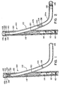
- FIG. 1 an exemplary junction 100 between a main wellbore 102 and a lateral wellbore 104 is illustrated.
- Main wellbore 102 is drilled using conventional techniques
- a main wellbore casing 106 is installed in main wellbore 102, and cement 108 is disposed between main wellbore 102 and main wellbore casing 106, using conventional techniques.
- a shearable work string having a window bushing locating profile 110, an orientation nipple 112, a multilateral packer assembly 114, a hollow whipstock 118, and a starter mill pilot lug (not shown) is run into main wellbore casing 106.
- Certain portions of such a work string are more fully disclosed in U.S Patent Nos. 5,613,559; 5,566,763; and 5,501,281
- the work string is located at the proper depth and orientation within main wellbore casing 106 using conventional pipe tally and/or gamma ray surveys for depth and measurement while drilling (MWD) orientation for azimuth.
- Packer assembly 114 is set against main wellbore casing 106 using slips, packing elements, and conventional hydraulic, mechanical, or hydraulic and mechanical setting techniques.
- whipstock 118 is used to guide work strings supporting a variety of tools and equipment to drill and complete lateral well bore 104.
- a series of mills such as a starter mill, a window mill, and a watermelon mill are used to create a window 120 in main wellbore casing 106.
- a drilling motor is used to drill lateral wellbore 104 from window 120.
- a lateral wellbore liner 122 is then disposed within lateral wellbore 104, and sealant 124 is disposed between lateral wellbore 104 and liner 122.
- liner 122 preferably has a generally cylindrical axial bore and a generally cylindrical external surface.
- Liner 122 is preferably made from steel, steel alloys, plastic, or other materials conventionally used for lateral liners.
- a work string 128 having a liner hanger 130, wiper plugs 132 and 133, and liner 122 is run down main wellbore casing 106 until liner 122 is deflected by hollow whipstock 118. This deflection causes liner 122 to be disposed in lateral wellbore 104 and junction 100.
- Liner hanger 130 and wiper plugs 132 and 133 remain disposed above window 120.
- Liner hanger 130 is then set against main wellbore casing 106 using conventional techniques.
- cementing of lateral wellbore 104 may be accomplished by either one or two-stage cementing depending on the length of wellbore 104.
- the length of lateral wellbore 104 is such that two stage cementing is preferred.
- liner 122 is equipped with a stage cementing tool 138.
- Stage cementing tool 138 is initially in a first position that allows fluid communication within liner 122 past tool 138, but does not allow fluid communication from liner 122 into the annulus between liner 122 and lateral wellbore 104.
- a first stage of cement 124a is pumped down drill string 128 and out a lower end 136 of liner 122
- First stage of cement 124a is preferably a conventional cement or conventional hardenable resin.
- a conventional wiper dart (not shown) is pumped down drill string 128 to land at wiper plugs 132 and 133. After landing, applied pressure releases wiper plug 132 and allows it to be pumped down to, and seal off, lower end 136 of liner 122.
- This displacement of wiper plug 132 causes first stage of cement 124a to flow throughout the annulus between liner 122 and lateral wellbore 104 up to stage cementing tool 138.
- An increase in pressure may be observed top hole by conventional pressure measuring devices upon the landing of wiper plug 132 in lower end 136.
- stage cementing tool 138 continues application of pressure moves stage cementing tool 138 to a second position that prevents fluid communication within liner 122 past stage cementing tool 138, but allows fluid communication from liner 122 into the annulus between liner 122 and lateral wellbore 104.
- a second stage of sealant 124b is then pumped down drill string 128 and into liner 122.
- a second wiper dart (not shown) is pumped down drill string 128 to land at wiper plug 133. After landing, applied pressure releases wiper plug 133 and allows it to be pumped down to, and seal off, liner 122 at stage cementing tool 138.
- wiper plug 133 causes second stage of sealant 124b to flow through stage cementing tool 138 and into the annulus between lateral wellbore 104, main wellbore casing 106, and liner 122 up to a top portion 134 of liner 122, positioning sealant 124b throughout junction 100.
- stage cementing tool 138 Once wiper plug 133 lands at stage cementing tool 138, continued application of pressure moves stage cementing tool 138 to a third position, preventing further circulation or backflow of sealant 124b.
- Sealant 124b is preferably a specialized multilateral junction cementitious sealant, or a specialized multilateral junction elastomeric sealant.
- a preferred example of such a cementitious sealant is M-SEAL ⁇ sold by Halliburton Energy Services of Carrollton, Texas.
- Such cementitious sealants are characterized by relatively low ductility and high compressive strength, as compared to such elastomeric sealants.
- a preferred example of such an elastomeric sealant is FLEX-CEM ⁇ sold by Halliburton Energy Services of Carrollton, Texas.
- Such elastomeric sealants are characterized by relatively high ductility and low compressive strength, as compared to such cementitious sealants.
- conventional cement or a conventional hardenable resin may be used as second stage sealant 124b.
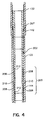
- Completion apparatus 200 preferably comprises a hollow mandrel having a lower packing assembly 202, an upper packing assembly 204, and a pressurization assembly 206.
- Completion apparatus 200 is preferably coupled to work string 128 above a supporting mandrel 140 for wiper plugs 132 and 133, and lower packing assembly 202, upper packing assembly 204, and pressurization assembly 206 are preferably coupled to each other by tool joints or other conventional means (not shown).
- liner 122 is preferably formed with a no-go shoulder 142 and an annular polished bore receptacle 144 below no-go shoulder 142.
- lower packing assembly 202 preferably includes a seal assembly 205, and a no-go sleeve 207 for mating with no-go shoulder 142 of liner 122
- Seal assembly 205 preferably comprises a plurality of annular sealing elements 208, such as conventional o-rings or packing devices, and an annular spacer member 210, both of which are disposed within an annular recess 212 on the external surface of lower packing assembly 202.
- Sealing elements 208 frictionally engage polished bore receptacle 144, which is located on the inner diameter of liner 122 and generally surrounds annular recess 212. Polished bore receptacle 144 cooperates with annular sealing elements 208 to create a fluid-tight seal.
- lower packing assembly 202 may comprise a conventional packer 220 having slips 222, packing elements 224, and actuating means 226.
- Packer 220 may be hydraulically, mechanically, or hydraulically and mechanically set via actuating means 226 so that packing elements 224 create a fluid tight seal against liner 122.
- liner 122 may be formed without no-go shoulder 142, if desired.
- Upper packing assembly 204 preferably has a substantially similar structure to lower packing assembly 202. If seal assembly 205 is utilized for lower packing assembly 202, upper packing assembly 204 preferably utilizes a similar seal assembly that mates with a polished bore receptacle located on the inner diameter of liner 122 below liner hanger 130. If packer 220 is used for lower packing assembly 202, upper packing assembly 204 preferably utilizes a similar packer designed to operate within the inner diameter of liner 122 proximate liner hanger 130. However, as shown in FIG. 3, upper packing assembly 204 does not require a no-go sleeve.
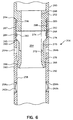
- Pressurization assembly 206 preferably comprises an a lower sub 250, an upper sub 252 removably coupled to lower sub 250, and a sealing sub 254 disposed within lower sub 250.
- Lower sub 250 preferably includes internally threaded ports 256a and 256b that provide a fluid communicating path between an axial bore 258 of lower sub 250 and an annulus 146 (FIG. 3) defined by an external surface 260 of pressurization assembly 206, an internal surface of liner 122, lower packing assembly 202, and upper packing assembly 204.
- Conventional rupture disks 262a and 262b are preferably removably contained in ports 256a and 256b, respectively. When contained in ports 256a and 256b, rupture disks 262a and 262b create a fluid tight seal between the interior of pressurization assembly 206 and annulus 146.
- a preferred rupture disk for rupture disks 262a and 262b is the disk sold by Oklahoma Safety Equipment Company (OSECO) of Broken Arrow, Oklahoma.
- OSECO Oklahoma Safety Equipment Company
- FIG. 6 Although not shown in FIG. 6, other conventional fluid bypass devices other than a rupture disk, such as a ball drop circulating valve, an internal pressure operated circulating valve, or other conventional circulating valve may be operatively coupled with ports 256a and 256b.
- a preferred internal pressure operated circulating valve is the IPO Circulating Valve sold by Halliburton Energy Services of Carrollton, Texas. All of these fluid bypass devices, including rupture disks 262a and 262b, have a first mode of operation that does not allow fluid to flow through ports 256a and 256b into annulus 146, and a second mode of operation that allows fluid to flow through ports 256a and 256b into annulus 146.
- Lower sub 250 also preferably includes ports 264a and 264b. Each of ports 264a and 264b provide a fluid communicating path between the interior of pressurization assembly 206 and annulus 146.
- Axial bore 258 preferably has an annular shoulder 265 and threads 267 disposed above ports 264a and 264b.
- Sealing sub 254 preferably includes an annular supporting member 266 and an annular, elastomeric sleeve 268 coupled to a lower end of supporting member 266.
- Sleeve 268 is preferably adhesively coupled to supporting member 266 along a portion 270 and shoulder 272 of support member 266.
- supporting member 266 and sleeve 268 define an axial bore 274 and an external surface 276.
- External surface 276 has an annular recess 278 proximate ports 264a and 264b; a shoulder 280 for mating with shoulder 265 of lower sub 250, and an annular slot 282 above annular recess 278.
- An o-ring 284 is disposed in slot 282 and creates a fluid tight seal between sealing sub 254 and lower sub 250. In its undeflected position, as shown in FIG. 6, a lower end 286 of sleeve 268 creates a fluid tight seal against axial bore 258 of lower sub 250.
- Upper sub 252 preferably includes an axial bore 288, an external surface 290, and a lower end 292.
- External surface 290 preferably includes an annular shoulder 294 for mating with lower sub 250, an annular slot 296, and threads 298 for removably engaging threads 267 of lower sub 250.
- An o-ring 300 is disposed within annular slot 296 to create a fluid tight seal between lower sub 250 and upper sub 252.
- Lower end 292 abuts support member 266 of sealing sub 254.
- completion apparatus 200 After wiper plug 133 is landed at, and seals off, stage cementing tool 138, work string 128 is pulled above top portion 134 of liner 122. Excess sealant within work string 128 and above top portion 134 of liner 122 is then circulated out of the well.
- a fluid tight seal is created proximate the end of work string 128 below lower packing assembly 202.
- a fluid tight seal is preferably formed using a wire-line plug, by pumping a plug down work string 128, or other conventional techniques.
- a preferred plug is the X-Lock ⁇ Plug sold by Halliburton Energy Services of Carrollton, Texas.
- a fluid such as water or drilling mud is pumped down work string 128. Due to the fluid tight seal created by the plug at the end work string 128, the pressure within pressurization assembly 206 is increased to the point where rupture disks 262a and 262b rupture. The rupturing of rupture disks 262a and 262b places the interior of pressurization assembly 206 in fluid communication with annulus 146 via ports 256a and 256b. Alternatively, if a fluid bypass device other than rupture disks are utilized, such pressurization causes the fluid bypass device to enter its second mode of operation that allows fluid to flow through ports 256a and 256b to annulus 146.
- the pressure within work string 128, and thus annulus 146 is preferably continuously and gradually increased so as to plastically deform the portion of liner 122 between lower packing assembly 202 and upper packing assembly 204 radially outward toward window 120, main wellbore casing 106, and lateral wellbore 104.
- sealant 124 proximate junction 100 such deformation of liner 122 must occur before the cementitious sealant or cement hardens.
- an elastomeric sealant is used for sealant 124 proximate junction 100, such deformation may occur before, or after, the elastomeric sealant hardens due to the ductility of the sealant.
- liner 122 provides significant advantages in the completion of junction 100.
- sealant 124 in the portion of the annulus between liner 122, main wellbore casing 106, and lateral wellbore 104 within junction 100 is placed in compression.
- Such compression provides a higher pressure rating for junction 100 during subsequent completion or production operations in the multilateral well.
- window 120 is defined by the intersection of cylindrical main wellbore casing 106 and generally cylindrical lateral wellbore 104, window 120 has a generally elliptical shape, with a major axis generally parallel to the longitudinal axis of main wellbore casing 106. Therefore, the outward deformation of liner 122 works to close the joints or gaps between liner 122 and window 120 present at the top and bottom of window 120. Such joint closure in turn minimizes leak paths, and thus leaks, within junction 100. In situations where the outward deformation of liner 122 may result in metal to metal contact of liner 122 and window 120, it is preferable to use a reinforced liner 122 to insure that any jagged or sharp edges on window 120 do not pierce liner 122.
- liner 122 increases the inner diameter of liner 122.
- This increase in inner diameter results in a larger flow path for petroleum from lateral wellbore 104, increasing the productivity of the well.
- This increase in inner diameter also results in a larger clearance for downhole tools to enter and exit lateral wellbore 104 during subsequent completion or production operations.
- a second work string with a sizing mandrel may optionally be run down main wellbore casing 106 and through junction 100 to insure adequate deformation of liner 122.
- Lateral liner 122a is formed with a grooved internal surface 500 and a grooved external surface 502.
- Liner 122a thus preferably has a cross-section 504 resembling a bellows.
- the geometry of grooved surfaces 500 and 502 facilitate the outward deformation of liner 122a at lower pressures.
- a lower pressure requirement for the outward deformation of liner 122a in turn reduces the risk of failure of the seals created by lower packing assembly 202 and upper packing assembly 204.
- liner 122a provides a larger, expanded outer diameter from a smaller, undeformed, run in outer diameter.
- grooved surfaces 500 and 502 preferably comprise grooves having a "sinusoidal" cross-section.
- grooved surfaces 500 and 502 may alternatively comprise grooves having a "saw tooth”, "square tooth”, or other cross-sectional geometry.
- preferably only the portion of liner 122a between lower packing assembly 202 and upper packing assembly 204 is formed with grooved external surface 502, and the remainder of liner 122a is formed with a generally cylindrical external surface.
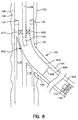
- Packing assembly 600 is preferably coupled to work string 128 above supporting mandrel 140, and packing assembly 600 preferably has a substantially identical structure to upper packing assembly 204 of completion apparatus 200.
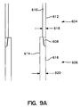
- Liner 602 is preferably comprised of an upper section 604, a lower section 606, and a tool joint or other conventional coupling mechanism 608 coupling upper section 604 and lower section 606.
- liner 602 can be machined to have upper section 604 and lower section 606, without the need for a coupling mechanism 608.
- liner 602 preferably includes a polished bore receptacle 610 located on the inner diameter of liner 602 below liner hanger 130. If packer 220 is used for packing assembly 600, polished bore receptacle 610 may be eliminated, if desired.
- upper section 604 and lower section 606 are made from the same material or casing grade.
- both upper section 604 and lower section 606 may be made of casing grade API N-80, which has a yield strength of approximately 80,000 psi (552 MPa).
- Upper section 604 preferably has a generally cylindrical axial bore 610 and a generally cylindrical external surface 612.
- Lower section 606 preferably has a generally cylindrical axial bore 614 a generally cylindrical external surface 616.
- upper section 604 has a wall thickness 618 smaller than a wall thickness 620 of lower section 606.
- upper section 604a preferably has a generally cylindrical axial bore 610a and a generally cylindrical external surface 612a.
- Lower section 606a has a generally cylindrical axial bore 614a a generally cylindrical external surface 616a.
- Upper section 604a has a wall thickness 618a substantially identical to a wall thickness 620a of lower section 606a.
- upper section 604a and lower section 606a are made from different materials or casing grades. More specifically, upper section 604a is made from a material or casing grade having a lower yield strength than the material or casing grade of lower section 606a.
- upper section 604a may be made from casing grade API K 55, which has a yield strength of approximately 55,000 psi (379 MPa), and lower section 606a may be made of casing grade API N-80, which has a yield strength of approximately 80,000 psi (552 MPa).
- upper section 604 may also be made from a casing grade having a lower yield strength that the casing grade used to make lower section 606.
- upper section 604a may also be formed with a smaller wall thickness 618a than wall thickness 620a of lower section 606a.
- liner 602 may be optimized so that for a given internal pressure, upper section 604 plastically deforms in a radially outward direction, and lower section 606 does not exhibit substantial radial deformation.
- a fluid such as water or drilling mud is pumped down work string 128 Due to the fluid tight seal created by packing assembly 600 against liner 602, fluid eventually fills all of liner 602 below packing assembly 600 down to wiper plug 133 sealed in stage cementing tool 138.
- the pressure within work string 128, and thus liner 602 is preferably continuously and gradually increased so as to plastically deform upper section 604 radially outward toward window 120, the portion of main wellbore casing 106 proximate window 120, and the portion of lateral wellbore 104 proximate window 120.
- lower section 606 preferably does not exhibit substantial radial deformation.
- upper section 604 provides substantially the same, significant advantages in the completion of junction 100 as described hereinabove for completion apparatus 200.
- upper section 604 may be formed with an external surface 612 similar to grooved external surface 502 of FIG. 7, if desired.
- Liner 700 has an interior cross-section 702 made from steel, steel alloys, plastic, or other generally non-elastomeric materials conventionally used for lateral liners.
- Interior cross-section 702 has an axial bore 704.
- Liner 700 further has an exterior cross-section 706 made from rubber or another conventional elastomeric material. When liner 700 is surrounded by sealant 124 and plastically deformed as described hereinabove, exterior cross-section 706 insures an adequate seal of junction 100.
- liner 700 may be plastically deformed as described hereinabove but without the use of sealant 124 in certain completions. In such completions, exterior cross-section 706 itself seals against window 120, main wellbore casing 106, and lateral wellbore 104.
- the present invention provides improved apparatus and methods for completing wellbores.
- the present invention provides such improved completion without inhibiting the amount or rate of well production, or substantially increasing the cost or complexity of the completion of the wellbore.
- the present invention allows the operations of running a lateral liner, sealing a lateral liner, and plastically deforming a lateral liner to be accomplished in a single downhole trip.
- the apparatus and methods of the present invention are economical to manufacture and use in a variety of downhole applications.
- the present invention is illustrated herein by example, and various modifications may be made by a person of ordinary skill in the art. For example, numerous geometries and/or relative dimensions could be altered to accommodate specific applications of the present invention. As another example, although the present invention has been described in connection with the completion of a junction between a main wellbore and a lateral wellbore in a multilateral well, it is fully applicable to the completion of a junction between a lateral wellbore and a second lateral wellbore extending from the lateral wellbore, to completion operations performed in other portions of a lateral wellbore other than such a junction, to completion operations performed in other portions of a main wellbore, to casing repair operations, or to window closures.
Landscapes
- Geology (AREA)
- Life Sciences & Earth Sciences (AREA)
- Engineering & Computer Science (AREA)
- Mining & Mineral Resources (AREA)
- Environmental & Geological Engineering (AREA)
- Fluid Mechanics (AREA)
- Physics & Mathematics (AREA)
- General Life Sciences & Earth Sciences (AREA)
- Geochemistry & Mineralogy (AREA)
- Earth Drilling (AREA)
- Sealing Devices (AREA)
- Gasket Seals (AREA)
- Luminescent Compositions (AREA)
- Pressure Vessels And Lids Thereof (AREA)
Claims (36)
- Ein Komplettierungsgerät für das Verkuppeln mit einer Arbeitskette (128) und für die Anwendung mit einem Futterrohr (122) eines Bohrloches, umfassend: eine erste Gleitdichteinheit (202) für das Erzeugen einer flüssigkeitsdichten Dichtung gegen das Futterrohr (122); eine zweite Gleitdichteinheit (204) für das Erzeugen einer zweiten flüssigkeitsdichten Dichtung gegen das Futterrohr (122); und eine Druckauferlegungseinheit (206), welche zwischen den ersten und zweiten Gleitdichteinheiten (202, 204) positioniert ist, dadurch gekennzeichnet, dass die hydraulische Druckauferlegung auf den Ringraum (146) einen Abschnitt des Futterrohres (122) dazu veranlaßt, sich zwischen der ersten Gleitdichteinheit (202) und der zweiten Gleitdichteinheit (204) in eine radial auswärtige Richtung zu verformen.
- Ein Komplettierungsgerät nach Anspruch 1, bei welchem die Druckauferlegungseinheit (206) eine Öffnung (256a, 256b) umfasst, welche sich in einen Ringraum (146) hinein öffnet, welcher durch die Druckauferlegungseinheit (206), das Futterrohr (122), die erste Gleitdichteinheit (202), und die zweite Gleitdichteinheit (204) definiert wird.
- Ein Komplettierungsgerät nach Anspruch 2, welches weiter eine Flüssigkeitsbeipaßvorrichtung umfasst, welche operativ mit der Öffnung (256a, 256b) gekoppelt ist, für das Verhindern einer Flüssigkeitsverbindung mit dem Ringraum (146) in einem ersten Betriebsmodus, und für das Ermöglichen einer hydraulischen Druckauferlegung auf den Ringraum (146) in einem zweiten Betriebsmodus.
- Ein Komplettierungsgerät nach Anspruch 3, bei welchem die Druckauferlegungseinheit (206) eine zweite Öffnung (264a, 264b) und eine Dichtungsuntereinheit (254) umfasst, welche operativ mit der zweiten Öffnung (264a, 264b) gekoppelt ist, für das Reduzieren von Druck innerhalb des Ringraums (146), wenn die ersten und zweiten Gleitdichtungseinheiten (202, 204) gegen das Futterrohr (122) abgedichtet sind.
- Ein Komplettierungsgerät nach Anspruch 3 oder 4, bei welchem die Flüssigkeitsbeipaßvorrichtung eine Berstscheibe (262a, 262b) umfasst.
- Ein Komplettierungsgerät nach einem der vorhergehenden Ansprüche, bei welchem die ersten und zweiten Gleitdichteinheiten (202, 204) Dichtungseinheiten umfassen, welche in polierte Bohrungsbehälter (144) eingepaßt werden, die in dem Futterrohr (122) positioniert sind.
- Ein Komplettierungsgerät nach einem der vorhergehenden Ansprüche, bei welchem die ersten und zweiten Gleitdichteinheiten (202, 204) Packer umfassen.
- Ein Komplettierungsgerät nach einem der vorhergehenden Ansprüche in Kombination mit einem Futterrohr (122) eines Bohrloches, bei welchem das Futterrohr (122) so adaptiert ist, dass dasselbe in einem multilateralen Bohrloch an einer Kreuzung (100) zwischen einem Hauptbohrloch (102) und einem lateralen Bohrloch (104) positioniert werden kann.
- Ein Komplettierungsgerät in Kombination mit einem Futterrohr nach Anspruch 8, bei welchem zumindest ein Abschnitt des Futterrohres (122) interne und externe Oberflächen mit Nuten umfasst.
- Ein Komplettierungsgerät in Kombination mit einem Futterrohr nach Anspruch 8 oder 9, bei welchem zumindest ein Abschnitt des Futterrohres (122) einen Innenquerschnitt umfasst, welcher aus einem allgemein nicht elastomerischen Material gefertigt wurde, und einen Außenquerschnitt, welcher aus einem allgemein elastomerischen Material gefertigt wurde.
- Die Anwendung eines Komplettierungsgeräts nach einem der vorhergehenden Ansprüche in einem lateralen Bohrloch (104).
- Eine Methode für das Komplettieren eines Bohrloches, welche die folgenden Schritte umfasst: das Positionieren eines Futterrohres (122) in einem Bohrloch; das Verkuppeln einer ersten Gleitdichteinheit (202), einer Druckauferlegungseinheit (206), und einer zweiten Gleitdichteinheit (204) mit einer Arbeitskette (128); das Einführen der Arbeitskette (128) in das Futterrohr (122); das Erzeugen einer flüssigkeitsdichten Dichtung zwischen der ersten Gleitdichteinheit (202) und dem Futterrohr (122); das Erzeugen einer flüssigkeitsdichten Dichtung zwischen der zweiten Gleitdichteinheit (204) und dem Futterrohr (122); das Pumpen von Flüssigkeit durch die Arbeitskette nach unten in die Druckauferlegungseinheit (206); das Anwenden der Druckauferlegungseinheit (206) und der Flüssigkeit für das Unterdrucksetzen eines Ringraums (146), welcher durch die Druckauferlegungseinheit (206), das Futterrohr (122), die erste Gleitdichteinheit (202), und die zweite Gleitdichteinheit (204) definiert wird; und durch das Steigern eines Drucks in dem Ringraum (146) gekennzeichnet, so dass das Futterrohr (122) in eine radial auswärtige Richtung verformt wird.
- Eine Methode nach Anspruch 12, bei welcher der Anwendungsschritt das Betätigen eines Flüssigkeitsbeipaßgerätes innerhalb der Druckauferlegungseinheit (206) für das Erzeugen eines Flüssigkeitskommunikationspfades zwischen einem Innenraum der Druckauferlegungseinheit (206) und dem Ringraum (146) umfasst.
- Eine Methode nach Anspruch 12 oder 13, bei welcher die ersten und zweiten Gleitdichteinheiten (202, 204) Dichtungseinheiten umfassen, welche in polierte Bohrungsbehälter (144) eingepaßt werden, welche in dem Futterrohr (122) positioniert sind.
- Eine Methode nach Anspruch 12, 13, oder 14, bei welcher die ersten und zweiten Gleitdichteinheiten (202, 204) Packer umfassen.
- Eine Methode nach Anspruch 12, 13, 14, oder 15, bei welcher zumindest ein Abschnitt des Futterrohres (122) interne und externe Oberflächen mit Nuten umfasst.
- Eine Methode nach einem der vorhergehenden Ansprüche 12 bis 16, welche weiter die Schritte des Flüssigkeitsabdichtens der Arbeitskette (128) in der Nähe der ersten Gleitdichteinheit (202) umfasst.
- Eine Methode nach einem der vorhergehenden Ansprüche 12 bis 17, bei welcher der Schritt des Positionierens des Futterrohres (122) umfasst: das Verkuppeln des Futterrohres (122) mit einem Ende der Arbeitskette (128); und das Einführen der Arbeitskette (128) in das Bohrloch.
- Eine Methode nach Anspruch 18, welche weiter den Schritt des Positionierens eines Dichtungsmittels (124) in einem zweiten Ringraum umfasst, welcher durch das Futterrohr (122) und das Bohrloch definiert wird.
- Eine Methode nach Anspruch 19, bei welcher der Schritt des Positionierens eines Dichtungsmittels (124) das Pumpen desselben Dichtungsmittels durch die Arbeitskette (128), die zweite Gleitdichteinheit (204), die Druckauferlegungseinheit (206), die erste Gleitdichteinheit (202), und das Futterrohr (122) hindurch in den zweiten Ringraum hinein umfasst.
- Eine Methode nach einem der Ansprüche 12 bis 20, bei welcher zumindest ein Abschnitt des Futterrohres (122) einen Innenquerschnitt umfasst, welcher aus einem allgemein nicht elastomerischen Material gefertigt wurde, und einen Außenquerschnitt, welcher aus einem allgemein elastomerischen Material gefertigt wurde.
- Eine Methode nach einem der Ansprüche 12 bis 21, bei welcher der Positionierungsschritt das Positionieren des Futterrohres (122) an einer Kreuzung (100) zwischen einem Hauptbohrloch (102) und einem lateralen Bohrloch (104) umfasst.
- Eine Methode nach Anspruch 22, bei welcher der Einführschritt das Einführen der Arbeitskette (128) in das Futterrohr (122) umfasst, bis die erste Gleitdichteinheit (202) hinter der Kreuzung (100) positioniert ist, und bis die zweite Gleitdichteinheit (204) vor der Kreuzung (100) positioniert ist.
- Eine Methode für das Komplettieren eines Bohrloches, welche die folgenden Schritte umfasst: das Positionieren eines Futterrohres (602) in einem Bohrloch, wobei das Futterrohr (602) einen ersten Abschnitt (604) und einen zweiten Abschnitt (606) umfasst, wobei der erste Abschnitt (604) bei einem niedrigeren Druck als demjenigen des zweiten Abschnitts in eine radial auswärtige Richtung verformbar ist; das Verkuppeln einer Gleitdichteinheit (600) mit einer Arbeitskette (128); das Einführen der Arbeitskette (128) in das Futterrohr (128); das Erzeugen einer flüssigkeitsdichten Dichtung zwischen der Gleitdichteinheit und dem Futterrohr (602); das Pumpen von Flüssigkeit in die Arbeitskette (128) hinunter, für das Unterdrucksetzen eines Innenraums des Futterrohres (602) hinter der Gleitdichteinheit (600); und durch das Steigern eines Drucks in dem Innenraum des Futterrohres (602) gekennzeichnet, um den ersten Abschnitt (604) des Futterrohres (602) in eine radial auswärtige Richtung zu verformen.
- Eine Methode nach Anspruch 24, bei welcher der erste Abschnitt (604) und der zweite Abschnitt (604) aus einem identischen Casing-Grad bestehen, und wobei der erste Abschnitt (604) eine geringere Wanddicke aufweist als der zweite Abschnitt.
- Eine Methode nach Anspruch 24, bei welcher der erste Abschnitt und der zweite Abschnitt (604, 606) eine identische Wanddicke aufweisen, und wobei der erste Abschnitt (604) aus einem ersten Casing-Grad, und der zweite Abschnitt (606) aus einem zweiten Casing-Grad mit einer größeren Fließgrenze als der des ersten Casing-Grades besteht.
- Eine Methode nach Anspruch 24, bei welcher: der erste Abschnitt (604) aus einem ersten Casing-Grad gefertigt ist und eine erste Wanddicke aufweist; und wobei der zweite Abschnitt (606) aus einem zweiten Casing-Grad mit einer größeren Fließgrenze als der des ersten Casing-Grades gefertigt ist, und wobei der zweite Abschnitt (606) über eine zweite Wanddicke verfügt, welche größer ist als die erste Wanddicke.
- Eine Methode nach einem der Ansprüche 24 to 27, bei welcher die Gleitdichteinheit (600) eine Dichtungseinheit umfaßt, welche in einen polierten Bohrungsbehälter (610) eingepaßt wird, welcher in dem Futterrohr (600) positioniert ist.
- Eine Methode nach einem der Ansprüche 24 bis 28, bei welcher die Gleitdichteinheit (602) einen Packer umfasst
- Eine Methode nach einem der Ansprüche 24 to 29, bei welcher zumindest ein Abschnitt des ersten Abschnitts (603) des Futterrohres (602) interne und externe Oberflächen mit Nuten umfasst.
- Eine Methode nach einem der Ansprüche 24 bis 30, bei welcher der Schritt des Positionierens des Futterrohres (602) umfasst: das Verkuppeln des Futterrohres (602) mit einem Ende der Arbeitskette (128); und das Einführen der Arbeitskette (128) in das Bohrloch.
- Eine Methode nach einem der Ansprüche 24 bis 31, welche weiter den Schritt des Positionierens eines Dichtungsmittels (124) in einem Ringraum umfasst, welcher durch das Futterrohr (602) und das Bohrloch definiert wird.
- Eine Methode nach Anspruch 32, bei welcher der Schritt des Positionierens des Dichtungsmittels (124) das Pumpen desselben Dichtungsmittels durch die Arbeitskette (128), die Gleitdichteinheit (600), und das Futterrohr (602) hindurch und in den Ringraum hinein umfasst.
- Eine Methode nach einem der Ansprüche 24 to 33, bei welcher der erste Abschnitt (604) einen Innenquerschnitt umfasst, welcher aus einem allgemein nicht elastomerischen Material gefertigt wird, und einen Außenquerschnitt, welcher aus einem allgemein elastomerischen Material gefertigt wird.
- Eine Methode nach einem der Ansprüche 24 bis 34, bei welcher der Positionierungsschritt das Positionieren des Futterrohres (602) an einer Kreuzung (102) zwischen einem Hauptbohrloch (102) und einem lateralen Bohrloch (104) umfasst, so dass der erste Abschnitt (604) sich durch die Kreuzung (100) hindurch erstreckt.
- Eine Methode nach Anspruch 35, bei welcher der Einführschritt das Einführen der Arbeitskette (128) in das Futterrohr (602) umfasst, bis die Gleitdichteinheit (600) vor der Kreuzung (600) positioniert ist.
Applications Claiming Priority (2)
| Application Number | Priority Date | Filing Date | Title |
|---|---|---|---|
| US28623 | 1998-02-24 | ||
| US09/028,623 US6138761A (en) | 1998-02-24 | 1998-02-24 | Apparatus and methods for completing a wellbore |
Publications (3)
| Publication Number | Publication Date |
|---|---|
| EP0937861A2 EP0937861A2 (de) | 1999-08-25 |
| EP0937861A3 EP0937861A3 (de) | 2001-03-21 |
| EP0937861B1 true EP0937861B1 (de) | 2005-04-13 |
Family
ID=21844488
Family Applications (1)
| Application Number | Title | Priority Date | Filing Date |
|---|---|---|---|
| EP99301350A Expired - Lifetime EP0937861B1 (de) | 1998-02-24 | 1999-02-24 | Verfahren und Vorrichtung zum Komplettieren einer Bohrung |
Country Status (5)
| Country | Link |
|---|---|
| US (2) | US6138761A (de) |
| EP (1) | EP0937861B1 (de) |
| BR (1) | BR9900483A (de) |
| CA (1) | CA2262452C (de) |
| NO (2) | NO317065B1 (de) |
Cited By (47)
| Publication number | Priority date | Publication date | Assignee | Title |
|---|---|---|---|---|
| US6892819B2 (en) | 1998-12-07 | 2005-05-17 | Shell Oil Company | Forming a wellbore casing while simultaneously drilling a wellbore |
| US6966370B2 (en) | 1999-02-26 | 2005-11-22 | Shell Oil Company | Apparatus for actuating an annular piston |
| US6968618B2 (en) | 1999-04-26 | 2005-11-29 | Shell Oil Company | Expandable connector |
| US6976541B2 (en) | 2000-09-18 | 2005-12-20 | Shell Oil Company | Liner hanger with sliding sleeve valve |
| US7011161B2 (en) | 1998-12-07 | 2006-03-14 | Shell Oil Company | Structural support |
| US7021390B2 (en) | 1998-12-07 | 2006-04-04 | Shell Oil Company | Tubular liner for wellbore casing |
| US7044218B2 (en) | 1998-12-07 | 2006-05-16 | Shell Oil Company | Apparatus for radially expanding tubular members |
| US7048067B1 (en) | 1999-11-01 | 2006-05-23 | Shell Oil Company | Wellbore casing repair |
| US7055608B2 (en) | 1999-03-11 | 2006-06-06 | Shell Oil Company | Forming a wellbore casing while simultaneously drilling a wellbore |
| US7100684B2 (en) | 2000-07-28 | 2006-09-05 | Enventure Global Technology | Liner hanger with standoffs |
| US7121352B2 (en) | 1998-11-16 | 2006-10-17 | Enventure Global Technology | Isolation of subterranean zones |
| US7146702B2 (en) | 2000-10-02 | 2006-12-12 | Shell Oil Company | Method and apparatus for forming a mono-diameter wellbore casing |
| US7147053B2 (en) | 1998-12-07 | 2006-12-12 | Shell Oil Company | Wellhead |
| US7168496B2 (en) | 2001-07-06 | 2007-01-30 | Eventure Global Technology | Liner hanger |
| US7168499B2 (en) | 1998-11-16 | 2007-01-30 | Shell Oil Company | Radial expansion of tubular members |
| US7172024B2 (en) | 2000-10-02 | 2007-02-06 | Shell Oil Company | Mono-diameter wellbore casing |
| US7185710B2 (en) | 1998-12-07 | 2007-03-06 | Enventure Global Technology | Mono-diameter wellbore casing |
| US7195064B2 (en) | 1998-12-07 | 2007-03-27 | Enventure Global Technology | Mono-diameter wellbore casing |
| US7231985B2 (en) | 1998-11-16 | 2007-06-19 | Shell Oil Company | Radial expansion of tubular members |
| US7234531B2 (en) | 1999-12-03 | 2007-06-26 | Enventure Global Technology, Llc | Mono-diameter wellbore casing |
| US7240728B2 (en) | 1998-12-07 | 2007-07-10 | Shell Oil Company | Expandable tubulars with a radial passage and wall portions with different wall thicknesses |
| US7243731B2 (en) | 2001-08-20 | 2007-07-17 | Enventure Global Technology | Apparatus for radially expanding tubular members including a segmented expansion cone |
| US7258168B2 (en) | 2001-07-27 | 2007-08-21 | Enventure Global Technology L.L.C. | Liner hanger with slip joint sealing members and method of use |
| US7267175B2 (en) | 2000-05-05 | 2007-09-11 | Weatherford/Lamb, Inc. | Apparatus and methods for forming a lateral wellbore |
| US7290605B2 (en) | 2001-12-27 | 2007-11-06 | Enventure Global Technology | Seal receptacle using expandable liner hanger |
| US7290616B2 (en) | 2001-07-06 | 2007-11-06 | Enventure Global Technology, L.L.C. | Liner hanger |
| US7308755B2 (en) | 2003-06-13 | 2007-12-18 | Shell Oil Company | Apparatus for forming a mono-diameter wellbore casing |
| US7350563B2 (en) | 1999-07-09 | 2008-04-01 | Enventure Global Technology, L.L.C. | System for lining a wellbore casing |
| US7360591B2 (en) | 2002-05-29 | 2008-04-22 | Enventure Global Technology, Llc | System for radially expanding a tubular member |
| US7363984B2 (en) | 1998-12-07 | 2008-04-29 | Enventure Global Technology, Llc | System for radially expanding a tubular member |
| US7377326B2 (en) | 2002-08-23 | 2008-05-27 | Enventure Global Technology, L.L.C. | Magnetic impulse applied sleeve method of forming a wellbore casing |
| US7383889B2 (en) | 2001-11-12 | 2008-06-10 | Enventure Global Technology, Llc | Mono diameter wellbore casing |
| US7398832B2 (en) | 2002-06-10 | 2008-07-15 | Enventure Global Technology, Llc | Mono-diameter wellbore casing |
| US7404444B2 (en) | 2002-09-20 | 2008-07-29 | Enventure Global Technology | Protective sleeve for expandable tubulars |
| US7410000B2 (en) | 2001-01-17 | 2008-08-12 | Enventure Global Technology, Llc. | Mono-diameter wellbore casing |
| US7416027B2 (en) | 2001-09-07 | 2008-08-26 | Enventure Global Technology, Llc | Adjustable expansion cone assembly |
| US7424918B2 (en) | 2002-08-23 | 2008-09-16 | Enventure Global Technology, L.L.C. | Interposed joint sealing layer method of forming a wellbore casing |
| US7503393B2 (en) | 2003-01-27 | 2009-03-17 | Enventure Global Technology, Inc. | Lubrication system for radially expanding tubular members |
| US7513313B2 (en) | 2002-09-20 | 2009-04-07 | Enventure Global Technology, Llc | Bottom plug for forming a mono diameter wellbore casing |
| US7516790B2 (en) | 1999-12-03 | 2009-04-14 | Enventure Global Technology, Llc | Mono-diameter wellbore casing |
| US7552776B2 (en) | 1998-12-07 | 2009-06-30 | Enventure Global Technology, Llc | Anchor hangers |
| US7571774B2 (en) | 2002-09-20 | 2009-08-11 | Eventure Global Technology | Self-lubricating expansion mandrel for expandable tubular |
| US7739917B2 (en) | 2002-09-20 | 2010-06-22 | Enventure Global Technology, Llc | Pipe formability evaluation for expandable tubulars |
| US7740076B2 (en) | 2002-04-12 | 2010-06-22 | Enventure Global Technology, L.L.C. | Protective sleeve for threaded connections for expandable liner hanger |
| US7775290B2 (en) | 2003-04-17 | 2010-08-17 | Enventure Global Technology, Llc | Apparatus for radially expanding and plastically deforming a tubular member |
| US7793721B2 (en) | 2003-03-11 | 2010-09-14 | Eventure Global Technology, Llc | Apparatus for radially expanding and plastically deforming a tubular member |
| US7918284B2 (en) | 2002-04-15 | 2011-04-05 | Enventure Global Technology, L.L.C. | Protective sleeve for threaded connections for expandable liner hanger |
Families Citing this family (75)
| Publication number | Priority date | Publication date | Assignee | Title |
|---|---|---|---|---|
| GB9712393D0 (en) * | 1997-06-14 | 1997-08-13 | Integrated Drilling Serv Ltd | Apparatus for and a method of drilling and lining a second borehole from a first borehole |
| US6640903B1 (en) | 1998-12-07 | 2003-11-04 | Shell Oil Company | Forming a wellbore casing while simultaneously drilling a wellbore |
| US6604763B1 (en) | 1998-12-07 | 2003-08-12 | Shell Oil Company | Expandable connector |
| US6634431B2 (en) | 1998-11-16 | 2003-10-21 | Robert Lance Cook | Isolation of subterranean zones |
| US6745845B2 (en) | 1998-11-16 | 2004-06-08 | Shell Oil Company | Isolation of subterranean zones |
| US6712154B2 (en) | 1998-11-16 | 2004-03-30 | Enventure Global Technology | Isolation of subterranean zones |
| US6575240B1 (en) | 1998-12-07 | 2003-06-10 | Shell Oil Company | System and method for driving pipe |
| US7603758B2 (en) | 1998-12-07 | 2009-10-20 | Shell Oil Company | Method of coupling a tubular member |
| GB9921557D0 (en) * | 1999-09-14 | 1999-11-17 | Petroline Wellsystems Ltd | Downhole apparatus |
| EG22306A (en) | 1999-11-15 | 2002-12-31 | Shell Int Research | Expanding a tubular element in a wellbore |
| US8746028B2 (en) * | 2002-07-11 | 2014-06-10 | Weatherford/Lamb, Inc. | Tubing expansion |
| GB0306774D0 (en) * | 2003-03-25 | 2003-04-30 | Weatherford Lamb | Hydraulically assisted tubing expansion |
| EP1626159B1 (de) * | 2000-05-05 | 2008-02-20 | Weatherford/Lamb, Inc. | Vorrichtung und Verfahren zur Herstellung einer Lateralbohrung |
| US6640895B2 (en) * | 2000-07-07 | 2003-11-04 | Baker Hughes Incorporated | Expandable tubing joint and through-tubing multilateral completion method |
| CA2414449C (en) * | 2000-07-28 | 2006-09-05 | Enventure Global Technology | Liner hanger with slip joint sealing members |
| WO2002053867A2 (en) | 2001-01-03 | 2002-07-11 | Enventure Global Technology | Mono-diameter wellbore casing |
| US7090025B2 (en) * | 2000-10-25 | 2006-08-15 | Weatherford/Lamb, Inc. | Methods and apparatus for reforming and expanding tubulars in a wellbore |
| US7121351B2 (en) * | 2000-10-25 | 2006-10-17 | Weatherford/Lamb, Inc. | Apparatus and method for completing a wellbore |
| US6755256B2 (en) * | 2001-01-19 | 2004-06-29 | Schlumberger Technology Corporation | System for cementing a liner of a subterranean well |
| US7350585B2 (en) | 2001-04-06 | 2008-04-01 | Weatherford/Lamb, Inc. | Hydraulically assisted tubing expansion |
| US6591905B2 (en) | 2001-08-23 | 2003-07-15 | Weatherford/Lamb, Inc. | Orienting whipstock seat, and method for seating a whipstock |
| US6688395B2 (en) * | 2001-11-02 | 2004-02-10 | Weatherford/Lamb, Inc. | Expandable tubular having improved polished bore receptacle protection |
| US7546881B2 (en) | 2001-09-07 | 2009-06-16 | Enventure Global Technology, Llc | Apparatus for radially expanding and plastically deforming a tubular member |
| ATE458123T1 (de) * | 2002-01-07 | 2010-03-15 | Enventure Global Technology | Schutzhülse für gewindeverbindungen für eine ausdehnbare liner-aufhängvorrichtung |
| US6814147B2 (en) * | 2002-02-13 | 2004-11-09 | Baker Hughes Incorporated | Multilateral junction and method for installing multilateral junctions |
| US6729410B2 (en) * | 2002-02-26 | 2004-05-04 | Halliburton Energy Services, Inc. | Multiple tube structure |
| US7073599B2 (en) * | 2002-03-21 | 2006-07-11 | Halliburton Energy Services, Inc. | Monobore wellbore and method for completing same |
| US6712148B2 (en) | 2002-06-04 | 2004-03-30 | Halliburton Energy Services, Inc. | Junction isolation apparatus and methods for use in multilateral well treatment operations |
| US6817633B2 (en) | 2002-12-20 | 2004-11-16 | Lone Star Steel Company | Tubular members and threaded connections for casing drilling and method |
| US7886831B2 (en) | 2003-01-22 | 2011-02-15 | Enventure Global Technology, L.L.C. | Apparatus for radially expanding and plastically deforming a tubular member |
| WO2004076798A2 (en) | 2003-02-26 | 2004-09-10 | Enventure Global Technology | Apparatus for radially expanding and plastically deforming a tubular member |
| US6907930B2 (en) * | 2003-01-31 | 2005-06-21 | Halliburton Energy Services, Inc. | Multilateral well construction and sand control completion |
| GB0303422D0 (en) * | 2003-02-13 | 2003-03-19 | Read Well Services Ltd | Apparatus and method |
| US6915847B2 (en) * | 2003-02-14 | 2005-07-12 | Schlumberger Technology Corporation | Testing a junction of plural bores in a well |
| CA2516140A1 (en) * | 2003-02-18 | 2004-09-02 | Enventure Global Technology | Protective compression and tension sleeves for threaded connections for radially expandable tubular members |
| US20040174017A1 (en) * | 2003-03-06 | 2004-09-09 | Lone Star Steel Company | Tubular goods with expandable threaded connections |
| US20070228729A1 (en) * | 2003-03-06 | 2007-10-04 | Grimmett Harold M | Tubular goods with threaded integral joint connections |
| US20040216506A1 (en) * | 2003-03-25 | 2004-11-04 | Simpson Neil Andrew Abercrombie | Tubing expansion |
| US7169239B2 (en) * | 2003-05-16 | 2007-01-30 | Lone Star Steel Company, L.P. | Solid expandable tubular members formed from very low carbon steel and method |
| GB2436115A (en) * | 2003-08-14 | 2007-09-19 | Enventure Global Technology | A tubular expansion device with lubricating coatings |
| US7712522B2 (en) | 2003-09-05 | 2010-05-11 | Enventure Global Technology, Llc | Expansion cone and system |
| GB2420811B (en) * | 2003-09-05 | 2008-03-19 | Enventure Global Technology | Radial expansion system |
| US7207390B1 (en) | 2004-02-05 | 2007-04-24 | Cdx Gas, Llc | Method and system for lining multilateral wells |
| WO2006033720A2 (en) * | 2004-08-11 | 2006-03-30 | Enventure Global Technology, Llc | Method of expansion |
| GB2432866A (en) | 2004-08-13 | 2007-06-06 | Enventure Global Technology | Expandable tubular |
| GB0420002D0 (en) * | 2004-09-09 | 2004-10-13 | Bp Exploration Operating | Method for drilling oil and gas wells |
| US7373984B2 (en) | 2004-12-22 | 2008-05-20 | Cdx Gas, Llc | Lining well bore junctions |
| US7299864B2 (en) | 2004-12-22 | 2007-11-27 | Cdx Gas, Llc | Adjustable window liner |
| US7640988B2 (en) | 2005-03-18 | 2010-01-05 | Exxon Mobil Upstream Research Company | Hydraulically controlled burst disk subs and methods for their use |
| CA2540990C (en) * | 2005-03-21 | 2015-11-24 | Bbj Tools Inc. | Method and tool for placing a well bore liner |
| US20070000664A1 (en) * | 2005-06-30 | 2007-01-04 | Weatherford/Lamb, Inc. | Axial compression enhanced tubular expansion |
| CA2555563C (en) | 2005-08-05 | 2009-03-31 | Weatherford/Lamb, Inc. | Apparatus and methods for creation of down hole annular barrier |
| US20070089875A1 (en) * | 2005-10-21 | 2007-04-26 | Steele David J | High pressure D-tube with enhanced through tube access |
| US7631699B2 (en) * | 2006-08-07 | 2009-12-15 | Baker Hughes Incorporated | System and method for pressure isolation for hydraulically actuated tools |
| US7686253B2 (en) * | 2006-08-10 | 2010-03-30 | The Boeing Company | Systems and methods for tracing aircraft vortices |
| US7757758B2 (en) * | 2006-11-28 | 2010-07-20 | Baker Hughes Incorporated | Expandable wellbore liner |
| US20090090516A1 (en) * | 2007-03-30 | 2009-04-09 | Enventure Global Technology, L.L.C. | Tubular liner |
| US8100188B2 (en) | 2007-10-24 | 2012-01-24 | Halliburton Energy Services, Inc. | Setting tool for expandable liner hanger and associated methods |
| US9551201B2 (en) | 2008-02-19 | 2017-01-24 | Weatherford Technology Holdings, Llc | Apparatus and method of zonal isolation |
| CA2715647C (en) | 2008-02-19 | 2013-10-01 | Weatherford/Lamb, Inc. | Expandable packer |
| US20100032167A1 (en) * | 2008-08-08 | 2010-02-11 | Adam Mark K | Method for Making Wellbore that Maintains a Minimum Drift |
| US8091633B2 (en) | 2009-03-03 | 2012-01-10 | Saudi Arabian Oil Company | Tool for locating and plugging lateral wellbores |
| US9725992B2 (en) * | 2010-11-24 | 2017-08-08 | Halliburton Energy Services, Inc. | Entry guide formation on a well liner hanger |
| US8499826B2 (en) | 2010-12-13 | 2013-08-06 | Baker Hughes Incorporated | Intelligent pressure actuated release tool |
| US8839873B2 (en) | 2010-12-29 | 2014-09-23 | Baker Hughes Incorporated | Isolation of zones for fracturing using removable plugs |
| US9816357B2 (en) * | 2013-10-10 | 2017-11-14 | Schlumberger Technology Corporation | Method and system to avoid premature activation of liner hanger |
| US9416638B2 (en) | 2014-06-24 | 2016-08-16 | Saudi Arabian Oil Company | Multi-lateral well system |
| GB201414256D0 (en) * | 2014-08-12 | 2014-09-24 | Meta Downhole Ltd | Apparatus and method of connecting tubular members in multi-lateral wellbores |
| RU2682288C2 (ru) * | 2014-10-01 | 2019-03-18 | Хэллибертон Энерджи Сервисиз, Инк. | Доступ в многоствольную скважину с передачей данных в режиме реального времени |
| US10081997B2 (en) * | 2015-11-18 | 2018-09-25 | Baker Hughes, A Ge Company, Llc | Watermelon mill with replaceable cutting structure |
| US11047413B2 (en) * | 2016-04-27 | 2021-06-29 | Hydril Company | Threaded and coupled tubular goods connection |
| WO2018200008A1 (en) * | 2017-04-29 | 2018-11-01 | Halliburton Energy Services, Inc. | Improved method and device for multilateral sealed junctions |
| US12326081B2 (en) | 2020-06-29 | 2025-06-10 | Baker Hughes Oilfield Operations Llc | Tagging assembly including a sacrificial stop component |
| US11692417B2 (en) * | 2020-11-24 | 2023-07-04 | Saudi Arabian Oil Company | Advanced lateral accessibility, segmented monitoring, and control of multi-lateral wells |
| US12416229B2 (en) * | 2021-06-07 | 2025-09-16 | Halliburton Energy Services, Inc. | 10,000-psi multilateral fracking system with large internal diameters for unconventional market |
Family Cites Families (35)
| Publication number | Priority date | Publication date | Assignee | Title |
|---|---|---|---|---|
| US2397070A (en) | 1944-05-10 | 1946-03-19 | John A Zublin | Well casing for lateral bores |
| US2452920A (en) | 1945-07-02 | 1948-11-02 | Shell Dev | Method and apparatus for drilling and producing wells |
| US2796134A (en) * | 1954-07-19 | 1957-06-18 | Exxon Research Engineering Co | Apparatus for preventing lost circulation in well drilling operations |
| US2797893A (en) | 1954-09-13 | 1957-07-02 | Oilwell Drain Hole Drilling Co | Drilling and lining of drain holes |
| US2812025A (en) * | 1955-01-24 | 1957-11-05 | James U Teague | Expansible liner |
| US2858107A (en) | 1955-09-26 | 1958-10-28 | Andrew J Colmerauer | Method and apparatus for completing oil wells |
| US3111991A (en) * | 1961-05-12 | 1963-11-26 | Pan American Petroleum Corp | Apparatus for repairing well casing |
| US3393744A (en) * | 1965-10-22 | 1968-07-23 | Razorback Oil Tool Co Inc | Inflatable packer |
| US3389752A (en) * | 1965-10-23 | 1968-06-25 | Schlumberger Technology Corp | Zone protection |
| US3412565A (en) * | 1966-10-03 | 1968-11-26 | Continental Oil Co | Method of strengthening foundation piling |
| US3489220A (en) * | 1968-08-02 | 1970-01-13 | J C Kinley | Method and apparatus for repairing pipe in wells |
| US4444276A (en) | 1980-11-24 | 1984-04-24 | Cities Service Company | Underground radial pipe network |
| US4396075A (en) | 1981-06-23 | 1983-08-02 | Wood Edward T | Multiple branch completion with common drilling and casing template |
| US4415205A (en) | 1981-07-10 | 1983-11-15 | Rehm William A | Triple branch completion with separate drilling and completion templates |
| US4402551A (en) | 1981-09-10 | 1983-09-06 | Wood Edward T | Method and apparatus to complete horizontal drain holes |
| FR2551491B1 (fr) | 1983-08-31 | 1986-02-28 | Elf Aquitaine | Dispositif de forage et de mise en production petroliere multidrains |
| US4569396A (en) * | 1984-10-12 | 1986-02-11 | Halliburton Company | Selective injection packer |
| US4718496A (en) * | 1987-01-05 | 1988-01-12 | Dresser Industries, Inc. | Method and apparatus for the completion of an oil or gas well and the like |
| US4807704A (en) | 1987-09-28 | 1989-02-28 | Atlantic Richfield Company | System and method for providing multiple wells from a single wellbore |
| EP0397874B1 (de) * | 1988-11-22 | 1997-02-05 | Tatarsky Gosudarstvenny Nauchno-Issledovatelsky I Proektny Institut Neftyanoi Promyshlennosti | Vorrichtung zum schliessen einer schwierigkeitszone in einem bohrloch |
| US5193621A (en) * | 1991-04-30 | 1993-03-16 | Halliburton Company | Bypass valve |
| US5353876A (en) | 1992-08-07 | 1994-10-11 | Baker Hughes Incorporated | Method and apparatus for sealing the juncture between a verticle well and one or more horizontal wells using mandrel means |
| US5474131A (en) | 1992-08-07 | 1995-12-12 | Baker Hughes Incorporated | Method for completing multi-lateral wells and maintaining selective re-entry into laterals |
| US5318122A (en) | 1992-08-07 | 1994-06-07 | Baker Hughes, Inc. | Method and apparatus for sealing the juncture between a vertical well and one or more horizontal wells using deformable sealing means |
| US5361836A (en) * | 1993-09-28 | 1994-11-08 | Dowell Schlumberger Incorporated | Straddle inflatable packer system |
| US5388648A (en) | 1993-10-08 | 1995-02-14 | Baker Hughes Incorporated | Method and apparatus for sealing the juncture between a vertical well and one or more horizontal wells using deformable sealing means |
| US5564503A (en) | 1994-08-26 | 1996-10-15 | Halliburton Company | Methods and systems for subterranean multilateral well drilling and completion |
| US5566763A (en) | 1994-08-26 | 1996-10-22 | Halliburton Company | Decentralizing, centralizing, locating and orienting subsystems and methods for subterranean multilateral well drilling and completion |
| US5549165A (en) * | 1995-01-26 | 1996-08-27 | Baker Hughes Incorporated | Valve for inflatable packer system |
| FR2735523B1 (fr) * | 1995-06-13 | 1997-07-25 | Inst Francais Du Petrole | Methode et dispositif de tubage de puits avec un tube en composite |
| FR2737534B1 (fr) * | 1995-08-04 | 1997-10-24 | Drillflex | Dispositif de chemisage d'une bifurcation d'un puits, notamment de forage petrolier, ou d'une canalisation, et procede de mise en oeuvre de ce dispositif |
| CA2169382C (en) * | 1996-02-13 | 2003-08-05 | Marvin L. Holbert | Method and apparatus for use in inflating packer in well bore |
| US5833001A (en) * | 1996-12-13 | 1998-11-10 | Schlumberger Technology Corporation | Sealing well casings |
| US5884704A (en) * | 1997-02-13 | 1999-03-23 | Halliburton Energy Services, Inc. | Methods of completing a subterranean well and associated apparatus |
| US5979560A (en) * | 1997-09-09 | 1999-11-09 | Nobileau; Philippe | Lateral branch junction for well casing |
-
1998
- 1998-02-24 US US09/028,623 patent/US6138761A/en not_active Expired - Lifetime
-
1999
- 1999-02-04 BR BR9900483-6A patent/BR9900483A/pt active Search and Examination
- 1999-02-19 NO NO19990784A patent/NO317065B1/no not_active IP Right Cessation
- 1999-02-22 CA CA002262452A patent/CA2262452C/en not_active Expired - Fee Related
- 1999-02-24 EP EP99301350A patent/EP0937861B1/de not_active Expired - Lifetime
-
2000
- 2000-01-18 US US09/483,980 patent/US6263968B1/en not_active Expired - Lifetime
-
2001
- 2001-05-02 NO NO20012162A patent/NO322414B1/no not_active IP Right Cessation
Cited By (82)
| Publication number | Priority date | Publication date | Assignee | Title |
|---|---|---|---|---|
| US7108072B2 (en) | 1998-11-16 | 2006-09-19 | Shell Oil Company | Lubrication and self-cleaning system for expansion mandrel |
| US7357190B2 (en) | 1998-11-16 | 2008-04-15 | Shell Oil Company | Radial expansion of tubular members |
| US7299881B2 (en) | 1998-11-16 | 2007-11-27 | Shell Oil Company | Radial expansion of tubular members |
| US7275601B2 (en) | 1998-11-16 | 2007-10-02 | Shell Oil Company | Radial expansion of tubular members |
| US7270188B2 (en) | 1998-11-16 | 2007-09-18 | Shell Oil Company | Radial expansion of tubular members |
| US7246667B2 (en) | 1998-11-16 | 2007-07-24 | Shell Oil Company | Radial expansion of tubular members |
| US7231985B2 (en) | 1998-11-16 | 2007-06-19 | Shell Oil Company | Radial expansion of tubular members |
| US7168499B2 (en) | 1998-11-16 | 2007-01-30 | Shell Oil Company | Radial expansion of tubular members |
| US7121352B2 (en) | 1998-11-16 | 2006-10-17 | Enventure Global Technology | Isolation of subterranean zones |
| US7240729B2 (en) | 1998-12-07 | 2007-07-10 | Shell Oil Company | Apparatus for expanding a tubular member |
| US7174964B2 (en) | 1998-12-07 | 2007-02-13 | Shell Oil Company | Wellhead with radially expanded tubulars |
| US7350564B2 (en) | 1998-12-07 | 2008-04-01 | Enventure Global Technology, L.L.C. | Mono-diameter wellbore casing |
| US7357188B1 (en) | 1998-12-07 | 2008-04-15 | Shell Oil Company | Mono-diameter wellbore casing |
| US7108061B2 (en) | 1998-12-07 | 2006-09-19 | Shell Oil Company | Expander for a tapered liner with a shoe |
| US7077211B2 (en) | 1998-12-07 | 2006-07-18 | Shell Oil Company | Method of creating a casing in a borehole |
| US7077213B2 (en) | 1998-12-07 | 2006-07-18 | Shell Oil Company | Expansion cone for radially expanding tubular members |
| US7086475B2 (en) | 1998-12-07 | 2006-08-08 | Shell Oil Company | Method of inserting a tubular member into a wellbore |
| US7048062B2 (en) | 1998-12-07 | 2006-05-23 | Shell Oil Company | Method of selecting tubular members |
| US7665532B2 (en) | 1998-12-07 | 2010-02-23 | Shell Oil Company | Pipeline |
| US7044218B2 (en) | 1998-12-07 | 2006-05-16 | Shell Oil Company | Apparatus for radially expanding tubular members |
| US7121337B2 (en) | 1998-12-07 | 2006-10-17 | Shell Oil Company | Apparatus for expanding a tubular member |
| US7363984B2 (en) | 1998-12-07 | 2008-04-29 | Enventure Global Technology, Llc | System for radially expanding a tubular member |
| US7021390B2 (en) | 1998-12-07 | 2006-04-04 | Shell Oil Company | Tubular liner for wellbore casing |
| US7147053B2 (en) | 1998-12-07 | 2006-12-12 | Shell Oil Company | Wellhead |
| US7159665B2 (en) | 1998-12-07 | 2007-01-09 | Shell Oil Company | Wellbore casing |
| US7552776B2 (en) | 1998-12-07 | 2009-06-30 | Enventure Global Technology, Llc | Anchor hangers |
| US7419009B2 (en) | 1998-12-07 | 2008-09-02 | Shell Oil Company | Apparatus for radially expanding and plastically deforming a tubular member |
| US7011161B2 (en) | 1998-12-07 | 2006-03-14 | Shell Oil Company | Structural support |
| US6892819B2 (en) | 1998-12-07 | 2005-05-17 | Shell Oil Company | Forming a wellbore casing while simultaneously drilling a wellbore |
| US7240728B2 (en) | 1998-12-07 | 2007-07-10 | Shell Oil Company | Expandable tubulars with a radial passage and wall portions with different wall thicknesses |
| US7036582B2 (en) | 1998-12-07 | 2006-05-02 | Shell Oil Company | Expansion cone for radially expanding tubular members |
| US7185710B2 (en) | 1998-12-07 | 2007-03-06 | Enventure Global Technology | Mono-diameter wellbore casing |
| US7195064B2 (en) | 1998-12-07 | 2007-03-27 | Enventure Global Technology | Mono-diameter wellbore casing |
| US7198100B2 (en) | 1998-12-07 | 2007-04-03 | Shell Oil Company | Apparatus for expanding a tubular member |
| US7216701B2 (en) | 1998-12-07 | 2007-05-15 | Shell Oil Company | Apparatus for expanding a tubular member |
| US7434618B2 (en) | 1998-12-07 | 2008-10-14 | Shell Oil Company | Apparatus for expanding a tubular member |
| US7040396B2 (en) | 1999-02-26 | 2006-05-09 | Shell Oil Company | Apparatus for releasably coupling two elements |
| US7556092B2 (en) | 1999-02-26 | 2009-07-07 | Enventure Global Technology, Llc | Flow control system for an apparatus for radially expanding tubular members |
| US7044221B2 (en) | 1999-02-26 | 2006-05-16 | Shell Oil Company | Apparatus for coupling a tubular member to a preexisting structure |
| US6966370B2 (en) | 1999-02-26 | 2005-11-22 | Shell Oil Company | Apparatus for actuating an annular piston |
| US7063142B2 (en) | 1999-02-26 | 2006-06-20 | Shell Oil Company | Method of applying an axial force to an expansion cone |
| US7055608B2 (en) | 1999-03-11 | 2006-06-06 | Shell Oil Company | Forming a wellbore casing while simultaneously drilling a wellbore |
| US7438132B2 (en) | 1999-03-11 | 2008-10-21 | Shell Oil Company | Concentric pipes expanded at the pipe ends and method of forming |
| US6968618B2 (en) | 1999-04-26 | 2005-11-29 | Shell Oil Company | Expandable connector |
| US7350563B2 (en) | 1999-07-09 | 2008-04-01 | Enventure Global Technology, L.L.C. | System for lining a wellbore casing |
| US7048067B1 (en) | 1999-11-01 | 2006-05-23 | Shell Oil Company | Wellbore casing repair |
| US7234531B2 (en) | 1999-12-03 | 2007-06-26 | Enventure Global Technology, Llc | Mono-diameter wellbore casing |
| US7516790B2 (en) | 1999-12-03 | 2009-04-14 | Enventure Global Technology, Llc | Mono-diameter wellbore casing |
| US7267175B2 (en) | 2000-05-05 | 2007-09-11 | Weatherford/Lamb, Inc. | Apparatus and methods for forming a lateral wellbore |
| US7100684B2 (en) | 2000-07-28 | 2006-09-05 | Enventure Global Technology | Liner hanger with standoffs |
| US6976541B2 (en) | 2000-09-18 | 2005-12-20 | Shell Oil Company | Liner hanger with sliding sleeve valve |
| US7172021B2 (en) | 2000-09-18 | 2007-02-06 | Shell Oil Company | Liner hanger with sliding sleeve valve |
| US7172024B2 (en) | 2000-10-02 | 2007-02-06 | Shell Oil Company | Mono-diameter wellbore casing |
| US7146702B2 (en) | 2000-10-02 | 2006-12-12 | Shell Oil Company | Method and apparatus for forming a mono-diameter wellbore casing |
| US7363691B2 (en) | 2000-10-02 | 2008-04-29 | Shell Oil Company | Method and apparatus for forming a mono-diameter wellbore casing |
| US7363690B2 (en) | 2000-10-02 | 2008-04-29 | Shell Oil Company | Method and apparatus for forming a mono-diameter wellbore casing |
| US7172019B2 (en) | 2000-10-02 | 2007-02-06 | Shell Oil Company | Method and apparatus for forming a mono-diameter wellbore casing |
| US7201223B2 (en) | 2000-10-02 | 2007-04-10 | Shell Oil Company | Method and apparatus for forming a mono-diameter wellbore casing |
| US7204007B2 (en) | 2000-10-02 | 2007-04-17 | Shell Oil Company | Method and apparatus for forming a mono-diameter wellbore casing |
| US7410000B2 (en) | 2001-01-17 | 2008-08-12 | Enventure Global Technology, Llc. | Mono-diameter wellbore casing |
| US7290616B2 (en) | 2001-07-06 | 2007-11-06 | Enventure Global Technology, L.L.C. | Liner hanger |
| US7168496B2 (en) | 2001-07-06 | 2007-01-30 | Eventure Global Technology | Liner hanger |
| US7258168B2 (en) | 2001-07-27 | 2007-08-21 | Enventure Global Technology L.L.C. | Liner hanger with slip joint sealing members and method of use |
| US7243731B2 (en) | 2001-08-20 | 2007-07-17 | Enventure Global Technology | Apparatus for radially expanding tubular members including a segmented expansion cone |
| US7416027B2 (en) | 2001-09-07 | 2008-08-26 | Enventure Global Technology, Llc | Adjustable expansion cone assembly |
| US7383889B2 (en) | 2001-11-12 | 2008-06-10 | Enventure Global Technology, Llc | Mono diameter wellbore casing |
| US7559365B2 (en) | 2001-11-12 | 2009-07-14 | Enventure Global Technology, Llc | Collapsible expansion cone |
| US7290605B2 (en) | 2001-12-27 | 2007-11-06 | Enventure Global Technology | Seal receptacle using expandable liner hanger |
| US7740076B2 (en) | 2002-04-12 | 2010-06-22 | Enventure Global Technology, L.L.C. | Protective sleeve for threaded connections for expandable liner hanger |
| US7918284B2 (en) | 2002-04-15 | 2011-04-05 | Enventure Global Technology, L.L.C. | Protective sleeve for threaded connections for expandable liner hanger |
| US7360591B2 (en) | 2002-05-29 | 2008-04-22 | Enventure Global Technology, Llc | System for radially expanding a tubular member |
| US7398832B2 (en) | 2002-06-10 | 2008-07-15 | Enventure Global Technology, Llc | Mono-diameter wellbore casing |
| US7424918B2 (en) | 2002-08-23 | 2008-09-16 | Enventure Global Technology, L.L.C. | Interposed joint sealing layer method of forming a wellbore casing |
| US7377326B2 (en) | 2002-08-23 | 2008-05-27 | Enventure Global Technology, L.L.C. | Magnetic impulse applied sleeve method of forming a wellbore casing |
| US7571774B2 (en) | 2002-09-20 | 2009-08-11 | Eventure Global Technology | Self-lubricating expansion mandrel for expandable tubular |
| US7404444B2 (en) | 2002-09-20 | 2008-07-29 | Enventure Global Technology | Protective sleeve for expandable tubulars |
| US7739917B2 (en) | 2002-09-20 | 2010-06-22 | Enventure Global Technology, Llc | Pipe formability evaluation for expandable tubulars |
| US7513313B2 (en) | 2002-09-20 | 2009-04-07 | Enventure Global Technology, Llc | Bottom plug for forming a mono diameter wellbore casing |
| US7503393B2 (en) | 2003-01-27 | 2009-03-17 | Enventure Global Technology, Inc. | Lubrication system for radially expanding tubular members |
| US7793721B2 (en) | 2003-03-11 | 2010-09-14 | Eventure Global Technology, Llc | Apparatus for radially expanding and plastically deforming a tubular member |
| US7775290B2 (en) | 2003-04-17 | 2010-08-17 | Enventure Global Technology, Llc | Apparatus for radially expanding and plastically deforming a tubular member |
| US7308755B2 (en) | 2003-06-13 | 2007-12-18 | Shell Oil Company | Apparatus for forming a mono-diameter wellbore casing |
Also Published As
| Publication number | Publication date |
|---|---|
| NO990784L (no) | 1999-08-25 |
| BR9900483A (pt) | 2000-01-18 |
| CA2262452A1 (en) | 1999-08-24 |
| NO990784D0 (no) | 1999-02-19 |
| NO322414B1 (no) | 2006-10-02 |
| EP0937861A2 (de) | 1999-08-25 |
| EP0937861A3 (de) | 2001-03-21 |
| CA2262452C (en) | 2008-01-08 |
| NO317065B1 (no) | 2004-08-02 |
| US6263968B1 (en) | 2001-07-24 |
| US6138761A (en) | 2000-10-31 |
| NO20012162D0 (no) | 2001-05-02 |
| NO20012162L (no) | 1999-08-25 |
Similar Documents
| Publication | Publication Date | Title |
|---|---|---|
| US6138761A (en) | Apparatus and methods for completing a wellbore | |
| US5031699A (en) | Method of casing off a producing formation in a well | |
| US5735350A (en) | Methods and systems for subterranean multilateral well drilling and completion | |
| CA2184943C (en) | Lateral seal and control system | |
| US5394941A (en) | Fracture oriented completion tool system | |
| US6073697A (en) | Lateral wellbore junction having displaceable casing blocking member | |
| US7575050B2 (en) | Method and apparatus for a downhole excavation in a wellbore | |
| CN1034973A (zh) | 建造钻井方法 | |
| GB2388130A (en) | Method and system for tubing a borehole in single diameter | |
| WO1998009053A9 (en) | Method and apparatus for sealing a junction on a multilateral well | |
| WO1998009053A2 (en) | Method and apparatus for sealing a junction on a multilateral well | |
| US6092593A (en) | Apparatus and methods for deploying tools in multilateral wells | |
| CA2276222C (en) | High pressure internal sleeve for use with easily drillable exit ports | |
| AU746677B2 (en) | Apparatus and methods for sealing a wellbore junction | |
| CA2592974C (en) | Apparatus and methods for completing a wellbore | |
| US12163401B2 (en) | Production sub including a fluid flow assembly having a pair of radial burst discs | |
| Robison | Monobore completions for slim-hole wells | |
| RU2844101C1 (ru) | Способ строительства многоствольной скважины и компоновка для бурения многоствольной скважины | |
| US20240117708A1 (en) | Production sub including degradable orifice | |
| AU752761B2 (en) | Apparatus and methods for sealing a wellbore junction | |
| CN121407852A (zh) | 一种套管钻井免固井管柱和施工方法 | |
| Sutherland et al. | Thin Walled Liner Hanger Equipment Enables Well Deepening Project | |
| GB2320735A (en) | Cementing method for the juncture between primary and lateral wellbores | |
| AU2018410835A1 (en) | Downhole check valve assembly with a frustoconical mandrel |
Legal Events
| Date | Code | Title | Description |
|---|---|---|---|
| PUAI | Public reference made under article 153(3) epc to a published international application that has entered the european phase |
Free format text: ORIGINAL CODE: 0009012 |
|
| AK | Designated contracting states |
Kind code of ref document: A2 Designated state(s): GB NL |
|
| AX | Request for extension of the european patent |
Free format text: AL;LT;LV;MK;RO;SI |
|
| RIC1 | Information provided on ipc code assigned before grant |
Free format text: 7E 21B 43/10 A, 7E 21B 33/10 B, 7E 21B 33/124 B |
|
| PUAL | Search report despatched |
Free format text: ORIGINAL CODE: 0009013 |
|
| AK | Designated contracting states |
Kind code of ref document: A3 Designated state(s): AT BE CH CY DE DK ES FI FR GB GR IE IT LI LU MC NL PT SE |
|
| AX | Request for extension of the european patent |
Free format text: AL;LT;LV;MK;RO;SI |
|
| 17P | Request for examination filed |
Effective date: 20010913 |
|
| AKX | Designation fees paid |
Free format text: GB NL |
|
| REG | Reference to a national code |
Ref country code: DE Ref legal event code: 8566 |
|
| 17Q | First examination report despatched |
Effective date: 20030915 |
|
| GRAP | Despatch of communication of intention to grant a patent |
Free format text: ORIGINAL CODE: EPIDOSNIGR1 |
|
| GRAS | Grant fee paid |
Free format text: ORIGINAL CODE: EPIDOSNIGR3 |
|
| GRAA | (expected) grant |
Free format text: ORIGINAL CODE: 0009210 |
|
| AK | Designated contracting states |
Kind code of ref document: B1 Designated state(s): GB NL |
|
| REG | Reference to a national code |
Ref country code: GB Ref legal event code: FG4D |
|
| PLBE | No opposition filed within time limit |
Free format text: ORIGINAL CODE: 0009261 |
|
| STAA | Information on the status of an ep patent application or granted ep patent |
Free format text: STATUS: NO OPPOSITION FILED WITHIN TIME LIMIT |
|
| 26N | No opposition filed |
Effective date: 20060116 |
|
| PGFP | Annual fee paid to national office [announced via postgrant information from national office to epo] |
Ref country code: NL Payment date: 20160205 Year of fee payment: 18 Ref country code: GB Payment date: 20160127 Year of fee payment: 18 |
|
| REG | Reference to a national code |
Ref country code: NL Ref legal event code: MM Effective date: 20170301 |
|
| GBPC | Gb: european patent ceased through non-payment of renewal fee |
Effective date: 20170224 |
|
| PG25 | Lapsed in a contracting state [announced via postgrant information from national office to epo] |
Ref country code: NL Free format text: LAPSE BECAUSE OF NON-PAYMENT OF DUE FEES Effective date: 20170301 |
|
| PG25 | Lapsed in a contracting state [announced via postgrant information from national office to epo] |
Ref country code: GB Free format text: LAPSE BECAUSE OF NON-PAYMENT OF DUE FEES Effective date: 20170224 |