EP0937384A2 - Portable press for straw, hay or similar crop - Google Patents
Portable press for straw, hay or similar crop Download PDFInfo
- Publication number
- EP0937384A2 EP0937384A2 EP99102224A EP99102224A EP0937384A2 EP 0937384 A2 EP0937384 A2 EP 0937384A2 EP 99102224 A EP99102224 A EP 99102224A EP 99102224 A EP99102224 A EP 99102224A EP 0937384 A2 EP0937384 A2 EP 0937384A2
- Authority
- EP
- European Patent Office
- Prior art keywords
- baler
- main frame
- machine
- bale
- packing
- Prior art date
- Legal status (The legal status is an assumption and is not a legal conclusion. Google has not performed a legal analysis and makes no representation as to the accuracy of the status listed.)
- Granted
Links
Images


Classifications
-
- A—HUMAN NECESSITIES
- A01—AGRICULTURE; FORESTRY; ANIMAL HUSBANDRY; HUNTING; TRAPPING; FISHING
- A01F—PROCESSING OF HARVESTED PRODUCE; HAY OR STRAW PRESSES; DEVICES FOR STORING AGRICULTURAL OR HORTICULTURAL PRODUCE
- A01F15/00—Baling presses for straw, hay or the like
- A01F15/07—Rotobalers, i.e. machines for forming cylindrical bales by winding and pressing
- A01F15/071—Wrapping devices
- A01F2015/0735—Combined machines that include a press bale and a wrapping device in a further step, e.g. turning table, not in the same closed pressing chamber
Definitions
- the invention relates to a mobile baler for straw, hay or similar stalks, which means of a main frame supported on wheels laterally rigid with a packaging machine a bale is detachably connected.
- the baler described above can be found in DE 4120733 A1.
- This press-wrap combination forms a compact machine unit that is easy to maneuver even on small areas creates favorable conditions for the transfer of bales from the baler to the wrapper.
- DE 196 13 657 A1 describes a changeover device for devices that can be attached to vehicles arresting, guiding and locking devices arranged at the separation point as well as matching ones Recordings known per se.
- the present invention has for its object to the baler described above improve that an extremely simple and quick changeover from combined operation of the Baler and the machine for packing the bales on solo operation is guaranteed. Furthermore should a shift in the center of mass in the combination compared to the solo press be taken into account in order to comply with the permissible support loads on the drawbar to the tractor.
- this object is achieved in that the Main frame on both sides of the baler a separation point with catch, guide and Locking devices and matching receptacles for locking one front each with a rear main frame part.
- the main frame is divided, the separation can take place at one point, the for the conversion of the device combination to solo operation with regard to the quick coupling, the Center of gravity shift and the constructive design is favorable.
- Both the baler as well as the machine for packing the bales with film can be constructed with little Operate effort as a single device and, if necessary, couple again practically using the one-man process.
- connection between the front and rear main frame part by flange connections on both sides which is preferred can be locked automatically.
- flange connections by combination with an adapter z.
- B. a simple one Coupling to the tractor's three-point hydraulic system or the tractor's drawbar.
- At least one axle, a tandem axle unit or each impeller individually essentially in the longitudinal direction of the baler is movable or pivotable by actuating an actuator and in combination operation of Bale press and machine for packing a bale with film is arranged offset to the rear relative to their position during solo operation of the baler.
- both sides of the tandem axle unit can be pivoted by hydraulically swiveling the vertically arranged rockers by e.g. B. 70 to 100 cm in the direction of travel. This position increases the maneuverability of the press and reduces the support loads on the drawbar to the tractor.
- the rear main frame part is hooked into the front main frame part and the axle assembly is moved backwards from its low front position until the carrying arms lift the packaging machine to remove its support feet.
- the front main frame part lowers again and locks the two main frame parts automatically.
- the center of gravity shifted to the rear is taken into account by moving the axle assembly backwards, in order to avoid negative support forces on the traction device.
- This embodiment also allows the packaging machine to be hung in the three-point hydraulic system of the tractor by means of an adapter for solo operation. Both the solo baler and the combination can be designed to be braked and / or resilient.
- each impeller is individually resiliently and / or hydraulically movably suspended on a drawn rocker arm, a front pair of impellers being assigned to the baler and a rear pair of impellers to the machine for packing a bale with film, with an intermediate separation point of the main frame .
- the height of the baler can be adjusted hydraulically from the slider seat for precise alignment of the connecting flanges of the separation point.
- the tandem axle assembly is easily separable with full adaptability of the individual axles.
- the sprung chassis allows higher driving speeds.
- the front wheels are advantageously equipped with brakes, which means that the solo baler remains brakable after separation.
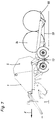
- FIG. 1 is a round baler 1, as z. B. is known from DE-PS 2443838, with a Drawbar 2 for attaching to a tractor, not shown, and with a support leg 3 for Shown the press shown.
- the round baler 1 is fixed on both sides with a essentially horizontally extending main frame 4 connected, which extends over an upward swiveling press housing part 5 extends backwards and a machine 6 for packaging the bale carries with film, consisting of an axis 7 lying transversely to the direction of travel X.
- the main frame 4 is made in two parts, with a front one belonging to the round baler Frame part 12 is supported on a biaxial chassis 13.
- the chassis 13 has on everyone Press side two wheels 14 arranged one behind the other, one on a horizontal and transverse to Direction lying axis 15 pendulum-mounted double rocker 16 are arranged.
- the Wheels 14 are mounted on the double rocker 16 by means of stub axles.
- Each pendulum axis is 15 connected to the front frame part 12 via an approximately vertically arranged support arm 17. Approximately in the middle between the two joints of the carrying arm 17 engages approximately in the direction of travel extending hydraulic cylinder 18 on the support arm 17, the other end on one down directed carrier 19 is articulated.
- the front frame part 12 ends in on each side of the press rearward direction with a sloping flange part 20 sloping from top to bottom at the front, the above a fixed, upwardly open catch hook 21 and below an open downward around an axis 22 has pivotable locking pawl 23, as can best be seen from FIG.
- the rear frame part 24 has a lower 25 at its front end on both sides of the press and upper cross bolts 26, which are fixed in a U-shaped counter flange 27 that is open in the direction of travel are arranged so that they can be brought into engagement with the catch hook 21 and the locking pawl 23 are.
- FIG. 1 the locked state of the front 12 and rear frame part 24 is shown.
- the upper Cross bolt 26 lies in the upper catch hook 21.
- the locking pawl 23 engages over the lower one Cross bolt 25. Characterized in that the support arm 17 with its back against the locking pawl 23rd presses, a positive locking is guaranteed.
- the hydraulic cylinder 18 is located in extended position and the two-axle chassis 23 is in the rear position 28, so that the No drawbar load on the drawbar 2 despite the saddled machine 6 for packing the bales with film assumes negative values, as would be the case if the round baler conformed to the axis arrangement Solo operation would have.
- the round baler 1 is attached to a tractor, which is a support leg 3 superscript. Is a bale pressed and z. B. strapped with net, the rear Press housing part 5 swung up and the bale thrown onto a rust-like intermediate floor, which is inclined backwards so that the bale rolit on the changing table 8 tilted forward and then wrapped in foil in the horizontal position of the changing table 8 and then through Tilting the changing table 8 backwards.
- the hydraulic cylinder 18 is retracted approximately half.
- the arrangement of the support rocker 17 is the main frame 4 pushed up and the two-axle chassis 13 pushed forward.
- the packaging machine 6 from FIG. 2 is connected to the tractor by means of an adapter part 31 connected, on the one hand the trailer bolts 32, 32a for the tractor three-point linkage 33 and on the other hand, not shown catch hooks and locking pawls according to FIGS. 1 and 2 for the Has transverse bolts 25, 26 of the rear frame part 24, so that the packaging machine alone is ready for operation.
- each impeller 34, 35 is in Drawn arrangement suspended on a rocker 36, 36a, the ends around axes 37, 37a are pivotable and are supported at the other end on hydraulic cylinders 38, 38a which are connected between rocker 36, 36a and frames 46, 46a are arranged. All four hydraulic cylinders 38, 38a are via oil lines 40, 41 connected with each other.
- the hydraulic system also has a hydraulic accumulator 42, two Stopcocks 43, 44, a quick coupling 45 and a connecting line, not shown to tractor hydraulics.
- the main frame 46, 46a is made in two parts, the press-side flange 47 on both Sides of the round baler 1 have an upper and lower centering pin 48 with an annular groove 49 has, while the winding device-side flange 50 matching the centering pin 48 has keyhole-shaped recesses 51, as can best be seen from FIG.
- the quick coupling 45 connects the oil lines 40 of the Round baler with 41 of the packaging machine 6.
- the shut-off valves 43, 44 are open and the hydraulic system is brought to a pressure value by means of the tractor hydraulics, which is a suspension the combination via the hydraulic accumulator 42 allowed.
- the wheels of the round baler can with Brakes, not shown, can be equipped for higher transport speeds.
- the combination is used to decouple the round baler 1 and the packaging machine 6 closed shut-off valve 44 raised by acting on the hydraulic cylinder 38, and the Packaging machine placed on support feet 52, which by slightly lowering the Round baler 1 follows, so that the centering pin 48 down from the rectangular Recesses 51 slide, whereby the unlocking of both units 1, 6 takes place.
- the stopcock 43 is closed and the quick coupling 45 is separated.
- Both units 1, 6 are now open own wheels 34 and 35 can be used in solo mode. Since both the packaging machine 6 own Impellers 35 and the baler 1 do not require any axis shifts.
Abstract
Description
Die Erfindung betrifft eine fahrbare Ballenpresse für Stroh, Heu oder ähnliches Halmgut, welche mittels eines sich auf Laufrädern abstützenden Hauptrahmens seitlich starr mit einer Maschine zum Verpacken eines Ballens lösbar verbunden ist.The invention relates to a mobile baler for straw, hay or similar stalks, which means of a main frame supported on wheels laterally rigid with a packaging machine a bale is detachably connected.
Die vorstehend beschriebene Ballenpresse läßt sich der DE 4120733 A 1 entnehmen. Diese Preß-Wickelkombination bildet eine kompakte Maschineneinheit, die auch auf kleinen Flächen gut zu rangieren ist und günstige Voraussetzungen für die Übergabe von Ballen aus der Ballenpresse zum Wickelgerät schafft.The baler described above can be found in DE 4120733 A1. This press-wrap combination forms a compact machine unit that is easy to maneuver even on small areas creates favorable conditions for the transfer of bales from the baler to the wrapper.
Diese Kombination hat aber einen entscheidenden Nachteil. Tritt an der Ballenpresse oder an der Wickelmaschine eine Störung auf, steht die ganze Kombination still. Auch beim Wechsel von Netz- oder Folienrolle wird weder gepreßt noch gewickelt. Beim Pressen von Heu oder Stroh ist ein Wickeln der Ballen nicht erwünscht, trotzdem muß die gesamte Maschine zum Verpacken der Ballen mit Folie mitgezogen und außer Betrieb gesetzt werden oder die Maschine zum Verpacken der Ballen ist von der Ballenpresse abzubauen wie in der DE 4120733 A 1 erwähnt.However, this combination has a major disadvantage. Occurs on the baler or on the If the winding machine breaks down, the whole combination stops. Even when changing from network or Film roll is neither pressed nor wrapped. When baling hay or straw is a winding of the Bale not desired, but the entire machine must be wrapped with foil pulled and put out of operation or the machine for packing the bales is from the Dismantle baler as mentioned in DE 4120733 A1.
Aus der DE 196 13 657 A1 sind bei einer Wechselvorrichtung für an Fahrzeuge anbringbare Geräte an der Trennstelle angeordnete Fang-, Führungs- und Verriegelungseinrichtungen sowie dazu passende Aufnahmen an sich bekannt.DE 196 13 657 A1 describes a changeover device for devices that can be attached to vehicles arresting, guiding and locking devices arranged at the separation point as well as matching ones Recordings known per se.
Der vorliegenden Erfindung liegt die Aufgabe zugrunde, die eingangs beschriebene Ballenpresse so zu verbessern, daß eine äußerst einfache und schnelle Umstellung von Kombinationsbetrieb der Ballenpresse und der Maschine zum Verpacken der Ballen auf Solobetrieb gewährleistet ist. Ferner soll eine Verlagerung des Massenschwerpunktes bei der Kombination im Vergleich zur Solopresse berücksichtigt werden, um zulässige Stützlasten an der Zugdeichsel zum Schlepper einzuhalten.The present invention has for its object to the baler described above improve that an extremely simple and quick changeover from combined operation of the Baler and the machine for packing the bales on solo operation is guaranteed. Furthermore should a shift in the center of mass in the combination compared to the solo press be taken into account in order to comply with the permissible support loads on the drawbar to the tractor.
Diese Aufgabe wird ausgehend von der eingangs beschriebenen Ballenpresse dadurch gelöst, daß der Hauptrahmen auf beiden Seiten der Ballenpresse eine Trennstelle mit Fang-, Führungs- und Verriegelungsvorrichtungen sowie dazu passende Aufnahmen zur Verriegelung jeweils eines vorderen mit einem hinteren Hauptrahmenteil aufweist.Starting from the baler described at the outset, this object is achieved in that the Main frame on both sides of the baler a separation point with catch, guide and Locking devices and matching receptacles for locking one front each with a rear main frame part.
Da erfindungsgemmäß der Hauptrahmen geteilt ausgeführt ist, kann die Trennung an einer Stelle erfolgen, die für die Umstellung der Gerätekombination auf Solobetrieb hinsichtlich der Schnellkuppelbarkeit, der Massenschwerpunktsverlagerung und der konstruktiven Gestaltung günstig ist. Sowohl die Ballenpresse als auch die Maschine zum Verpacken der Ballen mit Folie lassen sich mit geringem konstruktiven Aufwand als Einzelgerät betreiben und bei Bedarf praktisch im Einmannverfahren wieder kuppeln. Since, according to the invention, the main frame is divided, the separation can take place at one point, the for the conversion of the device combination to solo operation with regard to the quick coupling, the Center of gravity shift and the constructive design is favorable. Both the baler as well as the machine for packing the bales with film can be constructed with little Operate effort as a single device and, if necessary, couple again practically using the one-man process.
In weiterer Ausgestaltung der Erfindung wird vorgeschlagen, daß die Verbindung zwischen vorderem und hinterem Hauptrahmenteil durch beidseitige Flanschverbindungen erfolgt, welche vorzugsweise selbsttätig verriegelbar sind. Neben der guten Führungs- und Anlagefunktion für eine selbsttätige Verriegelung bietet eine Flanschverbindung durch Kombination mit einem Adapter z. B. ein einfaches Ankuppeln an die Dreipunkthydraulikanlage des Schleppers oder die Zugvorrichtung des Schleppers.In a further embodiment of the invention it is proposed that the connection between the front and rear main frame part by flange connections on both sides, which is preferred can be locked automatically. In addition to the good management and investment function for an automatic Locking offers a flange connection by combination with an adapter z. B. a simple one Coupling to the tractor's three-point hydraulic system or the tractor's drawbar.
Hinsichtlich der Berücksichtigung eines bei der Kombination nach hinten verschobenen Massenschwerpunktes zur Deichselstützlasteinstellung wird vorgeschlagen, daß wenigstens eine Achse, ein Tandemachsaggregat oder jedes Laufrad einzeln im wesentlichen in Längsrichtung der Ballenpresse durch Betätigung eines Stellorganes verschieb- oder verschwenkbar ist und bei Kombinationsbetrieb von Ballenpresse und Maschine zum Verpacken eines Ballens mit Folie nach hinten versetzt angeordnet ist relativ zu deren Position beim Solobetrieb der Ballenpresse.With regard to the consideration of a shifted backwards in the combination Center of gravity for setting the drawbar support load it is proposed that at least one axle, a tandem axle unit or each impeller individually essentially in the longitudinal direction of the baler is movable or pivotable by actuating an actuator and in combination operation of Bale press and machine for packing a bale with film is arranged offset to the rear relative to their position during solo operation of the baler.
Bekannte Kombinationsgeräte verteilen die erheblich höheren Traglasten bereits auf ein Tandemachsaggregat. Hierzu wird vorgeschlagen, daß an jeder Seite der Ballenpresse zwei Laufräder angeordnet sind, die in Fahrtrichtung hintereinander beidendig an Doppelschwingen gelagert sind, die ihrerseits um quer zur Fahrtrichtung liegende, mit den vorderen Hauptrahmenteilen oder mit dem Ballenpressenrahmen verbundenen Pendelachsen schwingbar sind, wobei der Hauptrahmen durch wenigstens ein Laufradpaar mittels eines Stellorganes anhebbar bzw. absenkbar ist. Außer der guten Bodenanpassung der Kombination gestattet diese Ausführung an Achsstummeln gelagerte Laufräder, während eine durchgehende Achse zumindest im hinteren Bereich die Ballenübergabe von Presse zu Verpackungsmaschine erschweren würde.Known combination devices already distribute the significantly higher loads on one Tandem axle unit. For this purpose, it is proposed that two impellers on each side of the baler are arranged, which are mounted at both ends on double rockers in the direction of travel, the in turn, around the direction of travel, with the front main frame parts or with the Baling frame connected pendulum axles are swingable, with the main frame through at least one pair of impellers can be raised or lowered by means of an actuator. Except for the good ones Adaptation to the ground of the combination allows this version of wheels mounted on stub axles, while a continuous axis at least in the rear area the bale transfer from the press to Packaging machine would complicate.
Ein besonders einfaches Anheben der Ballenpresse zum Kuppen bzw. Entkuppeln der
Verpackungsmaschine und gleichzeitig ein sehr einfaches Verfahren des Tandemachsaggregates zur
Stützlasteinstellung wird dadurch erzielt, daß beide Seiten der Pendelachse bzw. die Doppelschwingen
durch vertikal oder nahezu vertikal angeordnete Tragschwingen mit dem vorderen Hauptrahmenteil
verbunden und verstellbar sind. Für den Soloeinsatz der Ballenpresse können beide Seiten des
Tandemachsaggregates durch hydraulisches Verschwenken der vertikal angeordneten Schwingen um z.
B. 70 bis 100 cm in Fahrtrichtung verfahren werden. Diese Position erhöht die Wendigkeit der Presse und
verringert die Stützlasten an der Zugdeichsel zum Schlepper. Zur Kupplung von Ballenpresse und
Verpackungsmaschine wird der hintere Hauptrahmenteil in den vorderen Hauptrahmenteil eingehängt und
das Achsaggregat aus seiner vorderen tiefen Position soweit nach hinten verschoben, bis die
Tragschwingen die Verpackungsmaschine anheben, um deren Stützfüße zu entfernen. Durch
entsprechendes weiteres Verfahren des Tandemachsaggregates nach hinten senkt sich der vordere
Hauptrahmenteil wieder ab und verriegelt selbsttätig die beiden Hauptrahmenteile. Gleichzeitig wird durch
das Verschieben des Achsaggregates nach hinten der nach hinten verlagerte Massenschwerpunkt
berücksichtigt, um insbesondere auch negative Stützkrätte auf die Zugvorrichtung zu vermeiden. Diese
Ausführungsform gestattet auch, daß die Verpackungsmaschine mittels eines Adapters zum Solobetrieb
in die Dreipunkthydraulik des Schleppers gehängt wird. Sowohl Soloballenpresse als auch die
Kombination können bremsbar und / oder federnd ausgebildet sein. Um die mit einem stabilen Rahmen
und den Tandemachsen ausgestattete Ballenpresse im Stroh noch besser nutzen zu können, bietet es
sich an, statt der Verpackungsmaschine eine relativ einfache Ballensammelvorrichtung anzubringen.
Dadurch könnten bis zu drei Ballen auf dem Feld dicht beieinander abgelegt werden, was die Bergung
erheblich vereinfacht.
Eine andere Gestaltung der Erfindung sieht vor, daß jedes Laufrad einzeln federnd und / oder hydraulisch
beweglich an einer gezogenen Schwinge aufgehängt ist, wobei ein vorderes Laufradpaar der
Ballenpresse und ein hinteres Laufradpaar der Maschine zum Verpacken eines Ballens mit Folie
zugeordnet ist mit dazwischengelegener Trennstelle des Hauptrahmens. Zur genauen Ausrichtung der
Verbindungsflansche der Trennstelle kann die Höhe der Ballenpresse hydraulisch vom Schieppersitz
angepaßt werden. Das Tandemachsaggregat ist leicht trennbar mit voller Anpaßbarkeit der Einzelachsen.
Das gefederte Fahrwerk gestattet höhere Fahrgeschwindigkeiten. Die vorderen Laufräder sind vorteilhaft
mit Bremsen auszugestalten, wodurch auch die Solo-Ballenpresse nach der Trennung bremsbar bleibt.A particularly simple lifting of the baling press for coupling or uncoupling the packaging machine and at the same time a very simple method of the tandem axle unit for adjusting the vertical load is achieved in that both sides of the pendulum axis or the double rockers are connected to the front main frame part and adjustable by vertically or almost vertically arranged carrying arms are. For solo use of the baler, both sides of the tandem axle unit can be pivoted by hydraulically swiveling the vertically arranged rockers by e.g. B. 70 to 100 cm in the direction of travel. This position increases the maneuverability of the press and reduces the support loads on the drawbar to the tractor. To couple the baler and the packaging machine, the rear main frame part is hooked into the front main frame part and the axle assembly is moved backwards from its low front position until the carrying arms lift the packaging machine to remove its support feet. By correspondingly moving the tandem axle assembly to the rear, the front main frame part lowers again and locks the two main frame parts automatically. At the same time, the center of gravity shifted to the rear is taken into account by moving the axle assembly backwards, in order to avoid negative support forces on the traction device. This embodiment also allows the packaging machine to be hung in the three-point hydraulic system of the tractor by means of an adapter for solo operation. Both the solo baler and the combination can be designed to be braked and / or resilient. In order to be able to use the straw baler, which is equipped with a stable frame and the tandem axes, even better, it is advisable to install a relatively simple bale collecting device instead of the packaging machine. This would allow up to three bales to be placed close together on the field, which would make recovery much easier.
Another embodiment of the invention provides that each impeller is individually resiliently and / or hydraulically movably suspended on a drawn rocker arm, a front pair of impellers being assigned to the baler and a rear pair of impellers to the machine for packing a bale with film, with an intermediate separation point of the main frame . The height of the baler can be adjusted hydraulically from the slider seat for precise alignment of the connecting flanges of the separation point. The tandem axle assembly is easily separable with full adaptability of the individual axles. The sprung chassis allows higher driving speeds. The front wheels are advantageously equipped with brakes, which means that the solo baler remains brakable after separation.
Weitere Merkmale und Vorteile der Erfindung ergeben sich aus den übrigen Unteransprüchen und aus der nachfolgenden Beschreibung.Further features and advantages of the invention emerge from the remaining subclaims and the description below.
In der Zeichnung sind drei Ausführungsbeispiele dargestellt. Es zeigt
- Fig. 1
- eine Seitenansicht einer erfindungsgemäßen Ballenpresse mit einer aufgesattelten Maschine zum Verpacken der Ballen mit Folie und nach hinten gefahrenem Achsaggregat.
- Fig. 2
- eine Ansicht nach
Figur 1 bei abgehängter Maschine zum Verpacken der Ballen mit Folie und nach vorn gefahrenem Achsaggregat. - Fig. 3
- in Seitenansicht die Maschine zum Verpacken der Ballen mit Folie mittels Adapter angehängt in die Dreipunkthydraulik eines Zugschleppers,
- Fig. 4
- eine Seitenansicht eines zweiten Ausführungsbeispieles einer erfindungsgemäßen Ballenpresse mit einer aufgesattelten Maschine zum Verpacken der Ballen mit Folie und Einzelradaufhängung hydraulisch gefedert,
- Fig. 5
- eine Ansicht nach
Figur 4 bei abgehängter Maschine zum Verpacken der Ballen, - Fig. 6
- die Verriegelung von Ballenpresse und Maschine zum Verpacken der Ballen mit Folie als Einzelheit in vergrößertem Maßstab mit Ansichten von vorn und hinten im abgehängten Zustand der Maschine zum Verpacken der Ballen und
- Fig. 7.
- eine Seitenansicht einer Ballenpresse mit einem angebauten Ballensammler anstelle der Maschine zum Verpacken der Ballen mit Folie.
- Fig. 1
- a side view of a baler according to the invention with a saddled machine for packing the bales with film and the rear axle unit.
- Fig. 2
- a view of Figure 1 with the machine suspended for packing the bales with film and the axle unit moved forward.
- Fig. 3
- in side view the machine for packing the bales with film attached by an adapter to the three-point hydraulic system of a tractor
- Fig. 4
- a side view of a second embodiment of a baler according to the invention with a semi-mounted machine for packing the bales with film and independent wheel suspension hydraulically,
- Fig. 5
- 4 is a view according to FIG. 4 with the machine for packing the bales suspended,
- Fig. 6
- the locking of the baler and machine for packing the bales with film as a detail on an enlarged scale with views from the front and rear in the suspended state of the machine for packing the bales and
- Fig. 7.
- a side view of a baler with an attached bale collector instead of the machine for packing the bale with film.
In Figur 1 ist eine Rundballenpresse 1, wie sie z. B. aus der DE-PS 2443838 bekannt ist, mit einer
Zugdeichsel 2 zum Anhängen an einen nicht dargestellten Schlepper und mit einem Stützfuß 3 zum
Abstellen der Presse gezeigt. Die Rundballenpresse 1 ist auf beiden Seiten fest mit einem im
wesentlichen horizontal verlaufenden Hauptrahmen 4 verbunden, welcher sich über ein nach oben
aufschwenkbares Pressengehäuseteil 5 nach hinten hinauserstreckt und eine Maschine 6 zum Verpacken
der Ballen mit Folie tragt, bestehend aus einem um eine quer zur Fahrtrichtung X liegende Achse 7 nach
vorn und hinten kippbaren wickeltisch 8 mit antreibbaren Rollen 9, die einen Rundballen aufnehmen und
einem um eine hochgelegene, vertikale Achse drehbaren Doppel-Wickelarm 10 mit zwei Folienrollen 11,
der den sich drehenden Rundballen während seiner Rotation um eine horizontale Zylinderachse umkreist
und dabei mit Folie einwickelt.In Figure 1 is a
Der Hauptrahmen 4 ist zweiteilig ausgeführt, wobei ein vorderes, zur Rundballenpresse gehöriges
Rahmenteil 12 sich auf einem zweiachsigen Fahrwerk 13 abstützt. Das Fahrwerk 13 besitzt auf jeder
Pressenseite zwei hintereinanderangeordnete Laufräder 14, die an einer um eine horizontal und quer zur
Fahrtrichtung liegenden Achse 15 pendelbar gelagerten Doppelschwinge 16 angeordnet sind. Die
Laufräder 14 sind mittels Achsstummel an der Doppelschwinge 16 gelagert. Jede Pendelachse 15 ist
über eine etwa vertikal angeordnete Tragschwinge 17 mit dem vorderen Rahmenteil 12 verbunden. Etwa
mittig zwischen den beiden Gelenken der Tragschwinge 17 greift ein sich etwa in Fahrtrichtung
erstreckender Hydrozylinder 18 an der Tragschwinge 17 an, der anderenends an einem nach unten
gerichteten Träger 19 angelenkt ist. Der vordere Rahmenteil 12 endet auf jeder Seite der Presse in
rückwärtiger Richtung mit einem schräg von vorn oben nach hinten unten abfallenden Flanschteil 20, das
oben einen festen, nach oben offenen Fanghaken 21 und unten eine nach unten offene, um eine Achse
22 schwenkbare Verriegelungsklinke 23 aufweist, wie am besten aus Figur 2 ersichtlich ist.The
Der hintere Rahmenteil 24 weist an seinem vorderen Ende auf beiden Seiten der Presse einen unteren 25
und oberen Querbolzen 26 auf, die fest in einem U-förmigen, in Fahrtrichtung offenen Gegenflansch 27
angeordnet sind, so daß diese mit dem Fanghaken 21 und der Verriegelungsklinke 23 in Eingriff bringbar
sind.The
In Figur 1 ist der verriegelte Zustand von vorderem 12 und hinterem Rahmenteil 24 gezeigt. Der obere
Querbolzen 26 liegt in dem oberen Fanghaken 21. Die Verriegelungsklinke 23 übergreift den unteren
Querbolzen 25. Dadurch, daß die Tragschwinge 17 mit dem Rücken gegen die Verriegelungsklinke 23
drückt, ist eine formschlüssige Verriegelung gewährleistet. Der Hydrozylinder 18 befindet sich in
ausgefahrener Stellung und das zweiachsige Fahrwerk 23 befindet sich in hinterer Position 28, so daß die
Stützlast an der Zugdeichsel 2 trotz aufgesattelter Maschine 6 zum Verpacken der Ballen mit Folie keine
negativen Werte annimmt, wie es der Fall wäre, wenn die Rundballenpresse die Achsanordnung gemäß
Solobetrieb hätte.In Figure 1, the locked state of the front 12 and
Während des Betriebes ist die Rundballenpresse 1 an einen Schlepper angehängt, der Stützfuß 3 ist
hochgestellt. Ist ein Ballen fertiggepreßt und z. B. mit Netz umschnürt, wird das hintere
Pressengehäuseteil 5 hochgeschwenkt und der Ballen auf einen rostartigen Zwischenboden geworfen,
der nach rückwärts geneigt ist, so daß der Ballen auf den nach vorn gekippten Wickeltisch 8 rolit und
dann in Horizontalstellung des Wickeltisches 8 mit Folie umhüllt und anschließend durch
Nachhintenkippen des Wickeltisches 8 abgelegt wird.During operation, the
Soll nun beispielsweise Stroh gepreßt werden, das also nicht mit Folie umhüllt wird, so läßt sich die Kombination äußerst schnell auf Solobetrieb wie folgt umstellen.If, for example, straw is now to be pressed, which is therefore not covered with film, then the Change the combination extremely quickly to solo operation as follows.
Man fährt den Hydrozylinder 18 etwa die Hälfte ein. Durch die Anordnung der Tragschwinge 17, wird
dabei der Hauptrahmen 4 nach oben und das zweiachsige Fahrwerk 13 nach vorn geschoben. Man klappt
nun die Stützfüße 29 am hinteren Rahmenteil 24 aus und fährt das Fahrwerk 23 etwas nach vorn,
wodurch sich der Hauptrahmen 4 absenkt und eine selbsttätige Entriegelung von Fanghaken 21 / Bolzen
26 und Verriegelungsklinke 25 / Bolzen 23 stattfindet, die selbsttätig nach oben schwenken, da ihr
Rücken aufgrund der weggeschwenkten Tragschwinge 17 frei ist. Damit die Stützkräfte an der
Zugdeichsel die vorgeschriebenen Werte einnehmen, wird nunmehr durch Einfahren des Fahrwerkes
dieses in seine vordere Position 30 gebracht. Nach Lösen der Hydro- / bzw. Elektroverbindungen ist die
Presse allein betriebsbereit.The
Statt der pendelbar gelagerten, ungefederten Doppelschwingachse kann auch eine nicht dargestellte gefederte Tandemachse mit Verbundschwinge verwendet werden.Instead of the swing-mounted, unsprung double swinging axis, one that is not shown can also be used Suspended tandem axle with composite swing arm can be used.
In Figur 3 ist die Verpackungsmaschine 6 aus Figur 2 mittels eines Adapterteiles 31 mit dem Schlepper
verbunden, das einerseits die Anhängebolzen 32, 32a für die Schlepperdreipunkthydraulik-Anlenkung 33
und andererseits nicht dargestellte Fanghaken und Verriegelungsklinken gemäß Fig. 1 und 2 für die
Querbolzen 25, 26 des hinteren Rahmenteiles 24 aufweist, so daß auch die Verpackungsmaschine allein
betriebsbereit ist.In FIG. 3, the
In dem Ausführungsbeispiel nach den Figuren 4 bis 6 sind auch vier Laufräder 34, 35 für die Kombination
vorgesehen, jedoch ist der Rundballenpresse 1 auf beiden Seiten ein Laufrad 34 zugeordnet und auch die
Verpackungsmaschine 6 weist auf beiden Seiten ein Laufrad 35 auf. Jedes Laufrad 34, 35 ist in
gezogener Anordnung an je einer Schwinge 36, 36a aufgehängt, die einenends um Achsen 37, 37a
schwenkbar sind und sich anderenends an Hydrozylindern 38, 38a abstützen, die zwischen Schwinge 36,
36a und Rahmen 46, 46a angeordnet sind. Alle vier Hydrozylinder 38, 38a sind über Ölleitungen 40, 41
miteinander verbunden. Das Hydrauliksystem weist außerdem einen Hydrospeicher 42, zwei
Absperrhähne 43, 44, einen Schnellkuppelverschluß 45 und eine nicht dargestellte Verbindungsleitung
zur Schlepperhydraulik auf.In the exemplary embodiment according to FIGS. 4 to 6 there are also four running
Der Hauptrahmen 46, 46a ist zweigeteilt ausgeführt, wobei der pressenseitige Flansch 47 auf beiden
Seiten der Rundballenpresse 1 einen oberen und unteren Zentrierzapfen 48 mit einer Ringnut 49
aufweist, während der wickelgerätseitige Flansch 50 zu den Zentrierzapfen 48 passende
schlüssellochförmige Ausnehmungen 51 aufweist, wie am besten aus Figur 6 ersichtlich ist.The
Im angekuppelten Zustand von Rundballenpresse 1 und Verpackungsmaschine 6 gemäß Figur 4 greifen
die Ringnutquerschnitte 49 in eine rechteckförmige Aussparung 51a ein, so daß eine formschlüssige
Verriegelung gewährleistet ist. Der Schnellkuppelverschluß 45 verbindet die Ölleitungen 40 der
Rundballenpresse mit denen 41 der Verpackungsmaschine 6. Die Absperrhähne 43, 44 sind geöffnet und
das Hydrauliksystem ist mittels der Schlepperhydraulik auf einen Druckwert gebracht, der eine Federung
der Kombination über den Hydrospeicher 42 gestattet. Die Laufräder der Rundballenpresse können mit
nicht dargestellten Bremsen für höhere Transportgeschwindigkeiten ausgestattet sein.When the
Zum Entkuppeln von Rundballenpresse 1 und Verpackungsmaschine 6 wird die Kombination bei
geschlossenem Absperrhahn 44 durch Beaufschlagung der Hydrozylinder 38 angehoben, und die
Verpackungsmaschine auf Stützfüße 52 abgesetzt, welches durch geringfügiges Absenken der
Rundballenpresse 1 enfolgt, so daß die Zentrierzapfen 48 nach unten aus den rechteckförmigen
Ausnehmungen 51 gleiten, wodurch die Entriegelung beider Einheiten 1, 6 stattfindet. Der Absperrhahn
43 wird geschlossen und der Schnellkuppelverschluß 45 getrennt. Beide Einheiten 1, 6 sind nunmehr auf
eigenen Laufrädern 34 bzw. 35 im Solobetrieb einsetzbar. Da sowohl die Verpackungsmaschine 6 eigene
Laufräder 35 hat als auch die Ballenpresse 1 sind keine Achsverschiebungen nötig.The combination is used to decouple the
Bei dem in Figur 7 dargestellten Ausführungsbeispiel ist auf die Rundballenpresse 1 wie vorstehend
anhand zweier Ausführungsformen beschrieben statt der Verpackungsmaschine 6 ein an sich bekannter
Sammelrost 53 für zwei bis drei Rundballen 54 aufgesattelt. Die Rundballen 54 rollen auf den Rost 53 und
werden von einem abgabeseitigen Bügel 55 gehalten. Sind drei Ballen gesammelt, schwenkt der Bügel
55 nach unten, so daß drei Ballen an einer Stelle gesammelt abgeladen werden.In the embodiment shown in Figure 7 is on the
Claims (11)
Applications Claiming Priority (2)
| Application Number | Priority Date | Filing Date | Title |
|---|---|---|---|
| DE19806460 | 1998-02-17 | ||
| DE19806460A DE19806460C1 (en) | 1998-02-17 | 1998-02-17 | Mobile baler for straw, hay or similar stalks |
Publications (3)
| Publication Number | Publication Date |
|---|---|
| EP0937384A2 true EP0937384A2 (en) | 1999-08-25 |
| EP0937384A3 EP0937384A3 (en) | 2001-01-24 |
| EP0937384B1 EP0937384B1 (en) | 2004-08-11 |
Family
ID=7857963
Family Applications (1)
| Application Number | Title | Priority Date | Filing Date |
|---|---|---|---|
| EP99102224A Expired - Lifetime EP0937384B1 (en) | 1998-02-17 | 1999-02-05 | Portable press for straw, hay or similar crop |
Country Status (3)
| Country | Link |
|---|---|
| EP (1) | EP0937384B1 (en) |
| AT (1) | ATE272937T1 (en) |
| DE (2) | DE19806460C1 (en) |
Cited By (2)
| Publication number | Priority date | Publication date | Assignee | Title |
|---|---|---|---|---|
| WO2002076183A1 (en) * | 2001-03-22 | 2002-10-03 | Welmount Limited | A combined baler/bale wrapper |
| EP1386532A1 (en) * | 2002-08-03 | 2004-02-04 | Lely Enterprises AG | Device for wrapping of articles |
Families Citing this family (6)
| Publication number | Priority date | Publication date | Assignee | Title |
|---|---|---|---|---|
| DE19950138C1 (en) * | 1999-10-18 | 2000-12-28 | Josef Fischer | Auxiliary drive module for agricultural tractor fitted between tractor 3-point coupling and tractor attachment for providing extra traction force |
| DE20005963U1 (en) | 2000-03-31 | 2000-06-21 | Kverneland Gottmadingen Gmbh & | Agricultural machine |
| DE10240091A1 (en) * | 2002-08-28 | 2004-03-11 | Deere & Company, Moline | wrapping machine |
| EP1393614A3 (en) | 2002-08-28 | 2009-06-03 | Deere & Company | Wrapping device |
| DE102013108246A1 (en) * | 2013-08-01 | 2015-02-05 | Usines Claas France S.A.S. | Round agricultural baler |
| DE102013110626A1 (en) * | 2013-09-26 | 2015-03-26 | Usines Claas France S.A.S. | Round baler |
Citations (2)
| Publication number | Priority date | Publication date | Assignee | Title |
|---|---|---|---|---|
| DE4120733A1 (en) | 1991-06-22 | 1993-01-07 | Deere & Co | Machine for wrapping bales in foil - has mobile frame mounted rigidly to bale press with hydraulic ejector and transport frame |
| DE19613657A1 (en) | 1996-04-04 | 1997-10-09 | Alfred Soeder | Interchangeable appliance for vehicle-attached implements e.g. cultivators |
Family Cites Families (5)
| Publication number | Priority date | Publication date | Assignee | Title |
|---|---|---|---|---|
| DE2443838C3 (en) * | 1974-09-13 | 1982-09-02 | Gebrüder Welger GmbH & Co KG, 3340 Wolfenbüttel | Pick-up Roll Baler |
| US4815266A (en) * | 1987-09-30 | 1989-03-28 | Hesston Corporation | Continuous round baler with accumulating trailer |
| FR2651959B1 (en) * | 1989-09-20 | 1992-02-21 | Bugnot Ets | DEVICE FOR GROUPING CYLINDRICAL FORAGE BALES. |
| DE29711213U1 (en) * | 1997-06-27 | 1997-08-28 | Krone Bernhard Gmbh Maschf | Device for the continuous and airtight covering of bodies |
| DE19731520C2 (en) * | 1997-07-23 | 1999-08-05 | Bernd Biller | Device for pressing and wrapping round bales |
-
1998
- 1998-02-17 DE DE19806460A patent/DE19806460C1/en not_active Expired - Fee Related
-
1999
- 1999-02-05 AT AT99102224T patent/ATE272937T1/en not_active IP Right Cessation
- 1999-02-05 DE DE59910155T patent/DE59910155D1/en not_active Expired - Lifetime
- 1999-02-05 EP EP99102224A patent/EP0937384B1/en not_active Expired - Lifetime
Patent Citations (2)
| Publication number | Priority date | Publication date | Assignee | Title |
|---|---|---|---|---|
| DE4120733A1 (en) | 1991-06-22 | 1993-01-07 | Deere & Co | Machine for wrapping bales in foil - has mobile frame mounted rigidly to bale press with hydraulic ejector and transport frame |
| DE19613657A1 (en) | 1996-04-04 | 1997-10-09 | Alfred Soeder | Interchangeable appliance for vehicle-attached implements e.g. cultivators |
Cited By (6)
| Publication number | Priority date | Publication date | Assignee | Title |
|---|---|---|---|---|
| WO2002076183A1 (en) * | 2001-03-22 | 2002-10-03 | Welmount Limited | A combined baler/bale wrapper |
| CZ300561B6 (en) * | 2001-03-22 | 2009-06-17 | Welmount Limited | Combined baler wrapper |
| CN1531392B (en) * | 2001-03-22 | 2010-05-12 | 维尔芒特有限公司 | Combined baler/bale wrapper |
| US8091326B2 (en) | 2001-03-22 | 2012-01-10 | Welmount Limited | Combined baler/bale wrapper |
| US9237691B2 (en) | 2001-03-22 | 2016-01-19 | Welmount Limited | Combined baler/bale wrapper |
| EP1386532A1 (en) * | 2002-08-03 | 2004-02-04 | Lely Enterprises AG | Device for wrapping of articles |
Also Published As
| Publication number | Publication date |
|---|---|
| DE19806460C1 (en) | 1999-08-12 |
| EP0937384B1 (en) | 2004-08-11 |
| ATE272937T1 (en) | 2004-08-15 |
| EP0937384A3 (en) | 2001-01-24 |
| DE59910155D1 (en) | 2004-09-16 |
Similar Documents
| Publication | Publication Date | Title |
|---|---|---|
| DE2737053C3 (en) | Agricultural equipment | |
| EP0097347B1 (en) | Implement carrier | |
| DE19731520C2 (en) | Device for pressing and wrapping round bales | |
| EP0110056A2 (en) | Method and machine for handing round bales | |
| DE3501062C2 (en) | ||
| DE19806460C1 (en) | Mobile baler for straw, hay or similar stalks | |
| EP0784916A2 (en) | Vehicle for transporting an implement, in particular a wheeled implement | |
| EP0350514A1 (en) | Round-bale press | |
| DE3445222A1 (en) | DEVICE ON A MOTOR VEHICLE FOR PICKING UP AND SETTING DOWN AND TILTING CONTAINERS | |
| EP1186225A1 (en) | Combination of a baller, a wrapper and a chassis for attaching both elements | |
| DE2411726B1 (en) | Stack press for crops | |
| DE19928819A1 (en) | Baler | |
| EP0503396B1 (en) | Hay making machine | |
| DE4215599C2 (en) | Compost turning machine | |
| DE19618263A1 (en) | Device for swiveling the support arms of multi-rotor hay machines | |
| DE3304166C2 (en) | Round bale pick-up and transport vehicle | |
| DE3347220A1 (en) | Round-bale receiving, loading and transport vehicle | |
| DE3336313A1 (en) | GROUND SUPPORT UNIT FOR AN AGRICULTURAL MACHINE | |
| DE102013010669A1 (en) | harvester | |
| AT391787B (en) | DEVICE FOR TAKING SILAGE FROM A DRIVING SILO | |
| DE3407682A1 (en) | Appliance for pressing a crop | |
| DE1658415C (en) | Towed sweeper | |
| DE1630805C3 (en) | Attachable trailer | |
| DE19946249A1 (en) | Processing, compressing, transport and storage of agricultural products is carried out in container with walking press unit | |
| DE2553438A1 (en) | DEVICE FOR HANDLING HAY BALES OR FORAGE BALES |
Legal Events
| Date | Code | Title | Description |
|---|---|---|---|
| PUAI | Public reference made under article 153(3) epc to a published international application that has entered the european phase |
Free format text: ORIGINAL CODE: 0009012 |
|
| AK | Designated contracting states |
Kind code of ref document: A2 Designated state(s): AT CH DE FI FR GB IT LI NL |
|
| AX | Request for extension of the european patent |
Free format text: AL;LT;LV;MK;RO;SI |
|
| RAP3 | Party data changed (applicant data changed or rights of an application transferred) |
Owner name: LELY WELGER MASCHINENFABRIK GMBH |
|
| PUAL | Search report despatched |
Free format text: ORIGINAL CODE: 0009013 |
|
| AK | Designated contracting states |
Kind code of ref document: A3 Designated state(s): AT BE CH CY DE DK ES FI FR GB GR IE IT LI LU MC NL PT SE |
|
| AX | Request for extension of the european patent |
Free format text: AL;LT;LV;MK;RO;SI |
|
| 17P | Request for examination filed |
Effective date: 20010724 |
|
| AKX | Designation fees paid |
Free format text: AT CH DE FI FR GB IT LI NL |
|
| RAP1 | Party data changed (applicant data changed or rights of an application transferred) |
Owner name: LELY MASCHINENFABRIK GMBH |
|
| 17Q | First examination report despatched |
Effective date: 20020916 |
|
| GRAP | Despatch of communication of intention to grant a patent |
Free format text: ORIGINAL CODE: EPIDOSNIGR1 |
|
| RAP1 | Party data changed (applicant data changed or rights of an application transferred) |
Owner name: WELGER MASCHINENFABRIK GMBH |
|
| GRAS | Grant fee paid |
Free format text: ORIGINAL CODE: EPIDOSNIGR3 |
|
| GRAA | (expected) grant |
Free format text: ORIGINAL CODE: 0009210 |
|
| AK | Designated contracting states |
Kind code of ref document: B1 Designated state(s): AT CH DE FI FR GB IT LI NL |
|
| PG25 | Lapsed in a contracting state [announced via postgrant information from national office to epo] |
Ref country code: NL Free format text: LAPSE BECAUSE OF FAILURE TO SUBMIT A TRANSLATION OF THE DESCRIPTION OR TO PAY THE FEE WITHIN THE PRESCRIBED TIME-LIMIT Effective date: 20040811 Ref country code: IT Free format text: LAPSE BECAUSE OF FAILURE TO SUBMIT A TRANSLATION OF THE DESCRIPTION OR TO PAY THE FEE WITHIN THE PRESCRIBED TIME-LIMIT;WARNING: LAPSES OF ITALIAN PATENTS WITH EFFECTIVE DATE BEFORE 2007 MAY HAVE OCCURRED AT ANY TIME BEFORE 2007. THE CORRECT EFFECTIVE DATE MAY BE DIFFERENT FROM THE ONE RECORDED. Effective date: 20040811 Ref country code: FI Free format text: LAPSE BECAUSE OF FAILURE TO SUBMIT A TRANSLATION OF THE DESCRIPTION OR TO PAY THE FEE WITHIN THE PRESCRIBED TIME-LIMIT Effective date: 20040811 |
|
| REG | Reference to a national code |
Ref country code: GB Ref legal event code: FG4D Free format text: NOT ENGLISH |
|
| REG | Reference to a national code |
Ref country code: CH Ref legal event code: EP |
|
| REF | Corresponds to: |
Ref document number: 59910155 Country of ref document: DE Date of ref document: 20040916 Kind code of ref document: P |
|
| GBT | Gb: translation of ep patent filed (gb section 77(6)(a)/1977) |
Effective date: 20040906 |
|
| NLV1 | Nl: lapsed or annulled due to failure to fulfill the requirements of art. 29p and 29m of the patents act | ||
| PG25 | Lapsed in a contracting state [announced via postgrant information from national office to epo] |
Ref country code: AT Free format text: LAPSE BECAUSE OF NON-PAYMENT OF DUE FEES Effective date: 20050205 |
|
| PG25 | Lapsed in a contracting state [announced via postgrant information from national office to epo] |
Ref country code: LI Free format text: LAPSE BECAUSE OF NON-PAYMENT OF DUE FEES Effective date: 20050228 Ref country code: CH Free format text: LAPSE BECAUSE OF NON-PAYMENT OF DUE FEES Effective date: 20050228 |
|
| ET | Fr: translation filed | ||
| PLBE | No opposition filed within time limit |
Free format text: ORIGINAL CODE: 0009261 |
|
| STAA | Information on the status of an ep patent application or granted ep patent |
Free format text: STATUS: NO OPPOSITION FILED WITHIN TIME LIMIT |
|
| 26N | No opposition filed |
Effective date: 20050512 |
|
| REG | Reference to a national code |
Ref country code: CH Ref legal event code: PL |
|
| REG | Reference to a national code |
Ref country code: FR Ref legal event code: CD Owner name: LELY VERMEER MASCHINENFABRIK GMBH, DE Effective date: 20140507 |
|
| REG | Reference to a national code |
Ref country code: DE Ref legal event code: R081 Ref document number: 59910155 Country of ref document: DE Owner name: FORAGE COMPANY B.V., NL Free format text: FORMER OWNER: WELGER MASCHINENFABRIK GMBH, 38304 WOLFENBUETTEL, DE Effective date: 20140502 Ref country code: DE Ref legal event code: R081 Ref document number: 59910155 Country of ref document: DE Owner name: LELY MASCHINENFABRIK GMBH, DE Free format text: FORMER OWNER: WELGER MASCHINENFABRIK GMBH, 38304 WOLFENBUETTEL, DE Effective date: 20140502 Ref country code: DE Ref legal event code: R081 Ref document number: 59910155 Country of ref document: DE Owner name: LELY VERMEER MASCHINENFABRIK GMBH, DE Free format text: FORMER OWNER: WELGER MASCHINENFABRIK GMBH, 38304 WOLFENBUETTEL, DE Effective date: 20140502 |
|
| REG | Reference to a national code |
Ref country code: FR Ref legal event code: PLFP Year of fee payment: 17 |
|
| PGFP | Annual fee paid to national office [announced via postgrant information from national office to epo] |
Ref country code: GB Payment date: 20150226 Year of fee payment: 17 Ref country code: FR Payment date: 20150217 Year of fee payment: 17 |
|
| GBPC | Gb: european patent ceased through non-payment of renewal fee |
Effective date: 20160205 |
|
| REG | Reference to a national code |
Ref country code: FR Ref legal event code: ST Effective date: 20161028 |
|
| PG25 | Lapsed in a contracting state [announced via postgrant information from national office to epo] |
Ref country code: FR Free format text: LAPSE BECAUSE OF NON-PAYMENT OF DUE FEES Effective date: 20160229 Ref country code: GB Free format text: LAPSE BECAUSE OF NON-PAYMENT OF DUE FEES Effective date: 20160205 |
|
| REG | Reference to a national code |
Ref country code: DE Ref legal event code: R081 Ref document number: 59910155 Country of ref document: DE Owner name: FORAGE COMPANY B.V., NL Free format text: FORMER OWNER: LELY VERMEER MASCHINENFABRIK GMBH, 38304 WOLFENBUETTEL, DE Ref country code: DE Ref legal event code: R081 Ref document number: 59910155 Country of ref document: DE Owner name: LELY MASCHINENFABRIK GMBH, DE Free format text: FORMER OWNER: LELY VERMEER MASCHINENFABRIK GMBH, 38304 WOLFENBUETTEL, DE |
|
| PGFP | Annual fee paid to national office [announced via postgrant information from national office to epo] |
Ref country code: DE Payment date: 20170427 Year of fee payment: 19 |
|
| REG | Reference to a national code |
Ref country code: DE Ref legal event code: R081 Ref document number: 59910155 Country of ref document: DE Owner name: FORAGE COMPANY B.V., NL Free format text: FORMER OWNER: LELY MASCHINENFABRIK GMBH, 38304 WOLFENBUETTEL, DE |
|
| REG | Reference to a national code |
Ref country code: DE Ref legal event code: R119 Ref document number: 59910155 Country of ref document: DE |
|
| PG25 | Lapsed in a contracting state [announced via postgrant information from national office to epo] |
Ref country code: DE Free format text: LAPSE BECAUSE OF NON-PAYMENT OF DUE FEES Effective date: 20180901 |