EP0937211B1 - Frein a disque a liaison rigide entre le socle du patin et le piston de manoeuvre - Google Patents
Frein a disque a liaison rigide entre le socle du patin et le piston de manoeuvre Download PDFInfo
- Publication number
- EP0937211B1 EP0937211B1 EP97946530A EP97946530A EP0937211B1 EP 0937211 B1 EP0937211 B1 EP 0937211B1 EP 97946530 A EP97946530 A EP 97946530A EP 97946530 A EP97946530 A EP 97946530A EP 0937211 B1 EP0937211 B1 EP 0937211B1
- Authority
- EP
- European Patent Office
- Prior art keywords
- adjusting
- load plate
- friction material
- pistons
- disc brake
- Prior art date
- Legal status (The legal status is an assumption and is not a legal conclusion. Google has not performed a legal analysis and makes no representation as to the accuracy of the status listed.)
- Expired - Lifetime
Links
Images

Classifications
-
- F—MECHANICAL ENGINEERING; LIGHTING; HEATING; WEAPONS; BLASTING
- F16—ENGINEERING ELEMENTS AND UNITS; GENERAL MEASURES FOR PRODUCING AND MAINTAINING EFFECTIVE FUNCTIONING OF MACHINES OR INSTALLATIONS; THERMAL INSULATION IN GENERAL
- F16D—COUPLINGS FOR TRANSMITTING ROTATION; CLUTCHES; BRAKES
- F16D65/00—Parts or details
- F16D65/14—Actuating mechanisms for brakes; Means for initiating operation at a predetermined position
- F16D65/16—Actuating mechanisms for brakes; Means for initiating operation at a predetermined position arranged in or on the brake
- F16D65/18—Actuating mechanisms for brakes; Means for initiating operation at a predetermined position arranged in or on the brake adapted for drawing members together, e.g. for disc brakes
- F16D65/183—Actuating mechanisms for brakes; Means for initiating operation at a predetermined position arranged in or on the brake adapted for drawing members together, e.g. for disc brakes with force-transmitting members arranged side by side acting on a spot type force-applying member
-
- F—MECHANICAL ENGINEERING; LIGHTING; HEATING; WEAPONS; BLASTING
- F16—ENGINEERING ELEMENTS AND UNITS; GENERAL MEASURES FOR PRODUCING AND MAINTAINING EFFECTIVE FUNCTIONING OF MACHINES OR INSTALLATIONS; THERMAL INSULATION IN GENERAL
- F16D—COUPLINGS FOR TRANSMITTING ROTATION; CLUTCHES; BRAKES
- F16D65/00—Parts or details
- F16D65/38—Slack adjusters
- F16D65/40—Slack adjusters mechanical
- F16D65/52—Slack adjusters mechanical self-acting in one direction for adjusting excessive play
- F16D65/56—Slack adjusters mechanical self-acting in one direction for adjusting excessive play with screw-thread and nut
- F16D65/567—Slack adjusters mechanical self-acting in one direction for adjusting excessive play with screw-thread and nut for mounting on a disc brake
- F16D65/568—Slack adjusters mechanical self-acting in one direction for adjusting excessive play with screw-thread and nut for mounting on a disc brake for synchronous adjustment of actuators arranged in parallel
-
- F—MECHANICAL ENGINEERING; LIGHTING; HEATING; WEAPONS; BLASTING
- F16—ENGINEERING ELEMENTS AND UNITS; GENERAL MEASURES FOR PRODUCING AND MAINTAINING EFFECTIVE FUNCTIONING OF MACHINES OR INSTALLATIONS; THERMAL INSULATION IN GENERAL
- F16D—COUPLINGS FOR TRANSMITTING ROTATION; CLUTCHES; BRAKES
- F16D2121/00—Type of actuator operation force
- F16D2121/14—Mechanical
-
- F—MECHANICAL ENGINEERING; LIGHTING; HEATING; WEAPONS; BLASTING
- F16—ENGINEERING ELEMENTS AND UNITS; GENERAL MEASURES FOR PRODUCING AND MAINTAINING EFFECTIVE FUNCTIONING OF MACHINES OR INSTALLATIONS; THERMAL INSULATION IN GENERAL
- F16D—COUPLINGS FOR TRANSMITTING ROTATION; CLUTCHES; BRAKES
- F16D2125/00—Components of actuators
- F16D2125/18—Mechanical mechanisms
- F16D2125/20—Mechanical mechanisms converting rotation to linear movement or vice versa
- F16D2125/22—Mechanical mechanisms converting rotation to linear movement or vice versa acting transversely to the axis of rotation
- F16D2125/28—Cams; Levers with cams
- F16D2125/32—Cams; Levers with cams acting on one cam follower
Definitions
- This invention relates to a vehicle disc brake system according to the preamble of claims 1 or 8.
- an input rotates an eccentric.
- the eccentric moves an actuating member to move a load plate and friction material into contact with a rotor.
- the friction material retards rotation of the rotor.
- the friction material is normally maintained slightly out of contact with the rotor. In that way, the rotor is able to rotate freely without impediment from the friction material. However, with wear, the friction material tends to be spaced further and further away from the rotor. Adjusting devices have been provided wherein adjusting sleeves adjust the starting position of an adjusting piston. This adjustment moves the friction material closer to the rotor in a non-braking position.
- the load plate has been connected to the adjusting piston through elastic clip connection. This has not always provided positive force transmission between the load plate and the piston.
- the brake pads which include the friction material experienced tangential wear. With tangential wear the brake may not fully utilize the friction material, and thus the pads require replacement more frequently than would otherwise be necessary.
- the prior art system utilized a clip, to connect the adjusting piston on the reverse side of the load plate.
- the resulting connection is not as reliable as would be desired.
- the prior art elastic clip connections have clipped the adjusting piston to the load plate on a first face of the load plate remote from the friction material. This not only results in the uneven wear as described above, but also makes the connection relatively difficult to reach, increasing the complexity of attaching the load plate to the adjusting pistons.
- US-A-3,837,437 defining the closest prior art discloses a pneumatically actuated brake system with two pistons on which an arcuate plate is attached.
- a load plate covered with a friction material on one side is connected to the arcuate plate which has a reduced dimension with respect to the load plate.
- the disk brake system according to the invention is characterized by an even wear. This is achieved by a disk brake system according to claims 1 or 8.
- the load plate is rigidly connected to the adjusting piston. In this way, the force transmitted to the load plate is directly centered and perpendicular to the friction surface. Thus, the wear on the friction surface is not tangential. Rather, there will be uniform wear across the friction surface, thus maximizing the useful life of the pad.
- the adjusting pistons are bolted to the piston head.
- a bolt hole extends through a side of the load plate that is to receive the friction material.
- the bolt extends through that bolt hole and into the adjusting piston. In this way a solid reliable connection is provided.
- the backing plate of the pad is secured outwardly of the bolts.
- a unique adjustment system is disclosed in a co-pending application.
- the adjusting system utilizes a gear driven adjuster to achieve movement of the adjusting piston.
- the inventive connection not only provides the benefits of the direct connection mentioned above, but also results in a relatively easily accessible connection.
- assembly of the load plate to the adjusting piston is simplified.
- uniform wear of the brake pads is achieved.
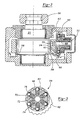
- a disc brake system 20 is illustrated in Figure 1.
- Brake system 20 incorporates an eccentric 22 which is selectably rotated to actuate a brake.
- An actuation block 24 is reciprocated by eccentric 22.
- actuation block 24 When actuation block 24 is moved (toward the top of the page in Figure 1), it drives adjusting sleeve 26. This in turn drives adjusting piston 28 forwardly.
- Load plate 30 is bolted 31 to adjusting piston 28.
- a brake pad including a backing plate 32 and friction material 34 is secured to adjusting load plate 30.
- the friction material 34 is shown with the brake actuated and in contact with the rotor 36.
- the friction material 34 is kept slightly out of contact with the rotor 36 when in a non-braking position.
- Bolts 31 secured load plate 30 to the adjusting piston 28 and provide a rigid, and centered, connection between the two. In this way, the force transmitted through block 24 is directly perpendicular to backing plate 22, and friction material 34. Thus, the wear on the friction material 34 is uniform. In the prior art, the wear has sometimes been tangential due to non-direct application of the actuating force.
- the load plate 30 includes bolt holes 33 extending from a side of the load plate that is to receive the friction material 30.
- the friction material 30 closes bolt holes 33.
- Bolts 31 extend through bolt holes 33 and into adjusting pistons 28.
- the bolt hole includes a smaller diameter portion 102 receiving a shaft 103 of bolt 31 and a greater diameter portion 104, with a head 105 of the bolt 31 abutting an end wall 106 between the greater diameter portion and the smaller diameter portion. This connection thus rigidly secures the backing plate 30 to the adjusting piston 28.
- Block 24 includes outer portion 38 that surrounds sleeves 26.
- a spring 40 holds sleeves 26 downwardly against block 24.
- a clip 42 provides a reaction surface for the spring 40, and is secured to sleeve 26.
- a threaded adjustment connection 44 between adjusting piston 28 and adjusting sleeve 26 allows for axial adjustment of the location of the piston and sleeve to compensate for wear of the friction material 34.
- a gear 46 is fixed to rotate with each sleeve 26, which in turn rotates the piston 28 forwardly.
- the pistons are constrained against rotation by bolts 31, and rotation by sleeves 26 moves piston 28 forwardly due to the threaded connection 44. This brings the location of the friction material 34 closer to the rotor 36.
- Gear 46 is rotated through idler gears 48 by an adjustment gear 50.
- a one-way clutch 52 insures that adjustment gear 50 is only rotated in a direction which causes the gears 46 to rotate and move friction material 34 closer to the rotor 36.
- the one-way clutch 52 does not allow reverse rotation, and may be a needle bearing one-way clutch as is known in the art.
- An over-torque load clutch 54 is also included and will be explained in more detail below.
- a pin 55 is fixed in block 24 and provides a mount spindle for clutch 54.
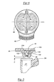
- the brake 20 is shown in Figure 2 with an actuating lever 56 connected to a drive, not shown.
- actuating member 56 When actuating member 56 is moved, it rotates the eccentric 22 to move the friction material as explained above.
- an adjustment gear section 58 rotates with the eccentric 22.
- Gear section 58 has teeth 60.
- Teeth 60 engage mating gear teeth 62 on an outer housing 63 which is incorporated into the over-torque clutch 54.
- Outer housing 63 rotates an inner housing 68 through the over-torque clutch 54.
- Inner housing 68 rotates adjustment gear 50 through the one-way clutch 52.
- FIG. 3 shows the over-torque clutch 54.
- Inner housing 68 is received within outer housing 63.
- Balls 70 are spring biased 72 outwardly of slots 74 in inner housing 68, and into grooves 76 in the outer housing 63.
- the adjustment gear section 58 includes teeth 60. Upon rotation of the eccentric 22, teeth 60 turn through a portion of a circle to a position such as shown in phantom at 80.
- Lever 56 rotates eccentric 22.
- Eccentric 22 moves actuating block 24 to move a sleeve 26, piston 28, load plate 30, backing plate 32, and friction material 34 toward the rotor 36.
- eccentric 22 may cause rotation of actuation gear section 58.
- Teeth 60 rotate teeth 62 and housing 63.
- over-torque clutch 54 drives inner housing 68. This in turn rotates the adjustment gear 50 through the one-way clutch 52.
- Rotation of gear 50 causes rotation of the idler gears 48 and adjustment gears 46. This causes sleeves 26 to rotate. Pistons 28 thus are advanced carrying the friction material toward the rotor 36.
- one-way clutch 52 allows the housing member 63 and 68 to return to a starting position without reversing any adjustment.
- Figure 5 shows the adjustment. As shown, piston 25 has been advanced a distance T.
- Figure 6 shows eccentric 22 received within a central bore on adjustment gear section 58.
- a groove 82 is formed at two locations on the gear section 58.
- Tabs 84 from eccentric 22 are received in grooves 82.
- the tabs 84 are smaller than groove 82, providing a clearance.
- tabs 84 were approximately 6 millimeter while grooves 82 were 8 millimeters.
Landscapes
- Engineering & Computer Science (AREA)
- General Engineering & Computer Science (AREA)
- Mechanical Engineering (AREA)
- Braking Arrangements (AREA)
Abstract
Claims (10)
- Un système de frein à disque (20) comprenant :caractérisé en ce que ladite plaque de charge (30) comprend au moins un trou pour chacun desdits pistons de réglage (28), lesdits trous s'étendant depuis ladite première face en direction d'un côté opposé de ladite plaque de charge (30) depuis ledit matériau de friction (34) et dans lequel chacun desdits pistons de réglage (28) est directement relié à ladite plaque de charge (30) sur ledit côté opposé par au moins un élément de liaison s'étendant à travers ladite plaque de charge (30) depuis ladite première face, à travers ledit trou dans ladite plaque de charge (30) et dans ledit piston de réglage (28) pour relier de manière sûre ledit piston de réglage (28) et pour fixer ladite plaque de charge (30) audit piston de réglage (28) par une liaison rigide de sorte qu'il ne se produise aucun déplacement relatif entre ladite plaque de charge (30) et ledit piston de réglage (28).une plaque de charge (30) unique pour recevoir d'un matériau de friction (34) sur une première face ;un excentrique (22) pour recevoir un couple d'actionnement d'entrée et un organe d'actionnement (56) pour déplacer ladite plaque de charge (30) et ledit matériau de friction (34) par rotation dudit excentrique (22) ;deux pistons de réglage (28) couplés chacun avec ladite plaque de charge (30), lesdits vérins de réglage (28) étant prévus pour régler la position de ladite plaque de charge (30) par rapport audit organe d'actionnement (56) pour compenser l'usure sur ledit matériau de friction (34) ; etune structure pour déplacer lesdits pistons de réglage (28) en cas d'usure dudit matériau de friction (34) ;
- Un système de frein à disque selon la revendication 1, dans lequel ledit matériau de friction (34) est positionné sur ladite première face de ladite plaque de charge (30) et recouvre ledit trou.
- Un système de frein à disque selon la revendication 1 ou 2, dans lequel ladite structure pour déplacer lesdits pistons de réglage (28) comprend une structure pour déplacer lesdits pistons de réglage (28) par rotation dudit excentrique (22).
- Un système de frein à disque selon l'une quelconque des revendications précédentes, dans lequel chacun desdits pistons de réglage (28) est vissé dans un manchon de réglage (26), ladite structure pour déplacer lesdits pistons de réglage (28) comprenant une structure pour tourner lesdits manchons de réglage (26).
- Un système de frein à disque selon l'une quelconque des revendications précédentes, dans lequel ladite structure pour déplacer lesdits vérins de réglage (28) comprend des manchons de réglage (26) reliés fonctionnellement pour être entraínés en rotation par des moyens de rotation, chaque piston de réglage (28) étant vissé dans un manchon de réglage (26), de sorte que, par rotation dudit manchon de réglage (26), ledit piston de réglage (28) soit avancé axialement.
- Un système de frein à disque selon l'une quelconque des revendications précédentes, dans lequel ledit élément de liaison est un boulon (31).
- Un système de frein à disque selon l'une quelconque des revendications précédentes, dans lequel ledit trou comprend une première partie de diamètre relativement petit (102) recevant une tige (103) dudit élément de liaison et une seconde partie (104) de plus grand diamètre recevant une tête (105) dudit élément de liaison, ladite tête (105) venant en lutée sur une face d'extrémité de ladite partie (104) de plus grand diamètre de sorte que ledit élément de connexion fixe rigidement ladite plaque de charge (30) audit piston de réglage (28).
- Un système de frein à disque comprenant :caractérisé en ce queune plaque de charge (30) unique ayant une première face pour recevoir un matériau de friction (34) et une seconde face pour être couplée aux pistons de réglage (28) ;un matériau de friction (34) reçu sur ladite première face de ladite plaque de charge (30) ;un excentrique (22) pour recevoir un couple d'actionnement d'entrée et un organe d'actionnement (56) pour déplacer ladite plaque de charge (30) et ledit matériau de friction (34) par rotation dudit excentrique (22) ;deux pistons de réglage (28), couplé chacun à ladite plaque de charge (30) pour régler la position de la partie de ladite plaque de charge (30) par rapport à l'organe d'actionnement (56) pour compenser l'usure sur ledit matériau de friction (34);une structure pour déplacer lesdits pistons de réglage (28) en cas d'usure dudit matériau de friction (34) ;
lesdits pistons (28) sont directement reliés à ladite plaque de charge (30) ;
une pluralité de trous de boulons s'étendant depuis ladite première face à travers ladite plaque de charge (30) jusqu'à ladite deuxième face, sont prévus ;
les boulons (31) qui s'étendent à travers lesdits trous de boulons et dans lesdits pistons de réglage (28) pour fixer directement et rigidement lesdits pistons de réglage (28) à ladite plaque de charge (30) étant prévus de sorte qu'il existe une liaisons rigide entre lesdits pistons de réglage (28) et ladite plaque de réglage (30) sans aucun mouvement relatif; et en ce que
ledit matériau de friction (34) entoure lesdits trous de boulons. - Un système de frein à disque selon la revendication 8, dans lequel ladite structure pour déplacer lesdits vérins de réglage (28) comprend au moins un manchon (26) pour chaque piston de réglage (28), lesdits manchons (26) recevant par lesdits pistons de réglage (28) étant vissés dans lesdits manchons (26) et ledit au moins un manchon (26) étant entraíné fonctionnellement de sorte que, par actionnement dudit excentrique (22), ledit manchon de réglage (26) soit entraíné en rotation pour faire avancer axialement ledit piston de réglage (28).
- Un système de frein à disque selon la revendication 8 ou 9, dans lequel lesdits trous de boulons comprennent une première partie (102) relativement petit de diamètre et recevant une tige (103) du boulon associé (31) et une deuxième partie (104) de plus grand diamètre recevant une tête (105) de boulon, ladite tête (105) venant en lutée sur une face d'extrémité de ladite partie (104) de plus grand diamètre de sorte que ledit boulon (31) fixe rigidement ladite plaque de charge (30) audit piston de réglage (28).
Applications Claiming Priority (3)
| Application Number | Priority Date | Filing Date | Title |
|---|---|---|---|
| US08/747,139 US5722516A (en) | 1996-11-12 | 1996-11-12 | Disc brake with rigid connection between load plate and adjusting piston |
| US747139 | 1996-11-12 | ||
| PCT/US1997/020146 WO1998021498A1 (fr) | 1996-11-12 | 1997-11-11 | Frein a disque a liaison rigide entre le socle du patin et le piston de manoeuvre |
Publications (2)
| Publication Number | Publication Date |
|---|---|
| EP0937211A1 EP0937211A1 (fr) | 1999-08-25 |
| EP0937211B1 true EP0937211B1 (fr) | 2003-10-08 |
Family
ID=25003807
Family Applications (1)
| Application Number | Title | Priority Date | Filing Date |
|---|---|---|---|
| EP97946530A Expired - Lifetime EP0937211B1 (fr) | 1996-11-12 | 1997-11-11 | Frein a disque a liaison rigide entre le socle du patin et le piston de manoeuvre |
Country Status (6)
| Country | Link |
|---|---|
| US (1) | US5722516A (fr) |
| EP (1) | EP0937211B1 (fr) |
| JP (1) | JP2001505285A (fr) |
| BR (1) | BR9713018B1 (fr) |
| DE (1) | DE69725461T2 (fr) |
| WO (1) | WO1998021498A1 (fr) |
Families Citing this family (10)
| Publication number | Priority date | Publication date | Assignee | Title |
|---|---|---|---|---|
| GB9518722D0 (en) * | 1995-09-13 | 1995-11-15 | Lucas Ind Plc | Improvements in electrically-operated disc brake assemblies for vehicles |
| SE508707C2 (sv) * | 1995-10-02 | 1998-10-26 | Volvo Ab | Anordning vid skivbromsar för motorfordon |
| BR0312964A (pt) * | 2002-07-29 | 2005-06-14 | Knorr Bremse Systeme F R Nutzf | Freio a disco com peça de pressão |
| US7931129B2 (en) * | 2003-01-31 | 2011-04-26 | Arvinmeritor Technology, Llc | Rapid take up and vibration proof adjuster mechanism |
| DE102008028265B4 (de) * | 2008-06-13 | 2015-04-02 | Knorr-Bremse Systeme für Nutzfahrzeuge GmbH | Nachstellvorrichtung für eine Scheibenbremse |
| DE102011115212A1 (de) * | 2011-09-28 | 2013-03-28 | Knorr-Bremse Systeme für Nutzfahrzeuge GmbH | Scheibenbremse für ein Nutzfahrzeug |
| DE102012006113A1 (de) * | 2012-03-26 | 2013-09-26 | Knorr-Bremse Systeme für Nutzfahrzeuge GmbH | Zuspannvorrichtung für eine drehhebelbetätigte Scheibenbremse |
| CN104428555B (zh) * | 2012-07-31 | 2016-12-07 | 相信Brake株式会社 | 具有齿轮连接件的车辆用盘式制动器 |
| KR101860581B1 (ko) * | 2013-07-26 | 2018-05-23 | 주식회사 만도 | 전동식 디스크 브레이크 장치 |
| US10114352B2 (en) | 2015-07-01 | 2018-10-30 | Fellowes, Inc. | Variable height platform device |
Family Cites Families (9)
| Publication number | Priority date | Publication date | Assignee | Title |
|---|---|---|---|---|
| US3837437A (en) * | 1973-01-22 | 1974-09-24 | Airheart Prod | Ratchet actuated brake wear compensation |
| GB1595492A (en) * | 1977-04-22 | 1981-08-12 | Girling Ltd | Brakes |
| DE3431773A1 (de) * | 1984-08-29 | 1986-03-13 | Deutsche Perrot-Bremse Gmbh, 6800 Mannheim | Mechanisch betaetigte gleitsattelscheibenbremse |
| DE4031616C2 (de) * | 1990-10-05 | 1999-11-25 | Perrot Bremse Gmbh Deutsche | Automatische Nachstelleinrichtung für eine mechanisch betätigte Gleitsattel-Scheibenbremse |
| EP0639246B1 (fr) * | 1992-05-05 | 1996-01-17 | Lucas Industries Public Limited Company | Dispositif de commande avec rattrapage de jeu automatique pour freins a disque, notamment pour poids lourds et autobus |
| EP0569031B1 (fr) * | 1992-05-08 | 1995-11-29 | DEUTSCHE PERROT-BREMSE GmbH | Dispositif de rattrapage de jeu pour un frein à disque |
| DE4308704A1 (de) * | 1993-03-18 | 1994-09-22 | Knorr Bremse Ag | Druckluftbetätigte Scheibenbremse |
| EP0703380A1 (fr) * | 1994-09-22 | 1996-03-27 | Rockwell International Corporation | Dispositif antirotation pour pistons d'un ensemble de frein à disque |
| EP0703381B1 (fr) * | 1994-09-22 | 2001-04-11 | Rockwell International Corporation | Douille de rajustage |
-
1996
- 1996-11-12 US US08/747,139 patent/US5722516A/en not_active Expired - Fee Related
-
1997
- 1997-11-11 DE DE69725461T patent/DE69725461T2/de not_active Expired - Fee Related
- 1997-11-11 WO PCT/US1997/020146 patent/WO1998021498A1/fr active IP Right Grant
- 1997-11-11 JP JP52264598A patent/JP2001505285A/ja not_active Ceased
- 1997-11-11 BR BRPI9713018-4A patent/BR9713018B1/pt not_active IP Right Cessation
- 1997-11-11 EP EP97946530A patent/EP0937211B1/fr not_active Expired - Lifetime
Also Published As
| Publication number | Publication date |
|---|---|
| WO1998021498A1 (fr) | 1998-05-22 |
| DE69725461T2 (de) | 2004-06-24 |
| EP0937211A1 (fr) | 1999-08-25 |
| DE69725461D1 (de) | 2003-11-13 |
| BR9713018A (pt) | 2000-01-25 |
| BR9713018B1 (pt) | 2009-01-13 |
| US5722516A (en) | 1998-03-03 |
| JP2001505285A (ja) | 2001-04-17 |
Similar Documents
| Publication | Publication Date | Title |
|---|---|---|
| EP0937210B1 (fr) | Frein a disque a piston de reglage entraine par pignons | |
| US6315092B1 (en) | Electromechanically actuated disc brake | |
| US5788022A (en) | Disc brake | |
| EP1269039B1 (fr) | Mecanisme de freinage | |
| US6820730B2 (en) | Brake lining wear adjuster assembly | |
| CA1183465A (fr) | Dispositif de reprise automatique du jeu aux freins | |
| EP0937211B1 (fr) | Frein a disque a liaison rigide entre le socle du patin et le piston de manoeuvre | |
| EP3564553B1 (fr) | Mécanisme de réglage | |
| EP3564552B1 (fr) | Mécanisme d'actionnement | |
| US5921356A (en) | Adjustable parking brake integrated with service brake | |
| EP1066478A1 (fr) | Actionneur pour frein a disques | |
| EP0129145A2 (fr) | Dispositif de rajustage pour un frein à disque | |
| KR100479512B1 (ko) | 유극 조절장치 | |
| EP0963520B1 (fr) | Mecanisme de reglage pour frein a disques, dote d'un embrayage a surcouple ameliore | |
| GB2329435A (en) | Apparatus for actuating a vehicle brake | |
| US3726367A (en) | Combined service and parking brake | |
| EP0125487B1 (fr) | Dispositif de rajustage pour un frein à disque | |
| US4702354A (en) | Brake actuator | |
| WO1998006608A2 (fr) | Mecanisme d'actionnement electromecanique pour ensemble de freins a disques | |
| EP0703380A1 (fr) | Dispositif antirotation pour pistons d'un ensemble de frein à disque | |
| US5147006A (en) | Friction clutch | |
| EP0703381B1 (fr) | Douille de rajustage | |
| GB2097888A (en) | Vehicle two-axle drive mechanism with parking brake | |
| EP0703379A1 (fr) | Mécanisme de rajustage pour un frein à disque | |
| JP2549842Y2 (ja) | パーキングブレーキ機構付きディスクブレーキ |
Legal Events
| Date | Code | Title | Description |
|---|---|---|---|
| PUAI | Public reference made under article 153(3) epc to a published international application that has entered the european phase |
Free format text: ORIGINAL CODE: 0009012 |
|
| 17P | Request for examination filed |
Effective date: 19990507 |
|
| AK | Designated contracting states |
Kind code of ref document: A1 Designated state(s): DE GB SE |
|
| 17Q | First examination report despatched |
Effective date: 20011221 |
|
| GRAH | Despatch of communication of intention to grant a patent |
Free format text: ORIGINAL CODE: EPIDOS IGRA |
|
| GRAS | Grant fee paid |
Free format text: ORIGINAL CODE: EPIDOSNIGR3 |
|
| GRAA | (expected) grant |
Free format text: ORIGINAL CODE: 0009210 |
|
| AK | Designated contracting states |
Kind code of ref document: B1 Designated state(s): DE GB SE |
|
| REG | Reference to a national code |
Ref country code: GB Ref legal event code: FG4D |
|
| REG | Reference to a national code |
Ref country code: SE Ref legal event code: TRGR |
|
| REF | Corresponds to: |
Ref document number: 69725461 Country of ref document: DE Date of ref document: 20031113 Kind code of ref document: P |
|
| PLBE | No opposition filed within time limit |
Free format text: ORIGINAL CODE: 0009261 |
|
| STAA | Information on the status of an ep patent application or granted ep patent |
Free format text: STATUS: NO OPPOSITION FILED WITHIN TIME LIMIT |
|
| 26N | No opposition filed |
Effective date: 20040709 |
|
| PGFP | Annual fee paid to national office [announced via postgrant information from national office to epo] |
Ref country code: SE Payment date: 20041122 Year of fee payment: 8 |
|
| PG25 | Lapsed in a contracting state [announced via postgrant information from national office to epo] |
Ref country code: SE Free format text: LAPSE BECAUSE OF NON-PAYMENT OF DUE FEES Effective date: 20051112 |
|
| PGFP | Annual fee paid to national office [announced via postgrant information from national office to epo] |
Ref country code: DE Payment date: 20060102 Year of fee payment: 9 |
|
| EUG | Se: european patent has lapsed | ||
| PG25 | Lapsed in a contracting state [announced via postgrant information from national office to epo] |
Ref country code: DE Free format text: LAPSE BECAUSE OF NON-PAYMENT OF DUE FEES Effective date: 20070601 |
|
| PGFP | Annual fee paid to national office [announced via postgrant information from national office to epo] |
Ref country code: GB Payment date: 20161128 Year of fee payment: 20 |
|
| REG | Reference to a national code |
Ref country code: GB Ref legal event code: PE20 Expiry date: 20171110 |
|
| PG25 | Lapsed in a contracting state [announced via postgrant information from national office to epo] |
Ref country code: GB Free format text: LAPSE BECAUSE OF EXPIRATION OF PROTECTION Effective date: 20171110 |