EP0936715A2 - Cable sleeve - Google Patents
Cable sleeve Download PDFInfo
- Publication number
- EP0936715A2 EP0936715A2 EP98123883A EP98123883A EP0936715A2 EP 0936715 A2 EP0936715 A2 EP 0936715A2 EP 98123883 A EP98123883 A EP 98123883A EP 98123883 A EP98123883 A EP 98123883A EP 0936715 A2 EP0936715 A2 EP 0936715A2
- Authority
- EP
- European Patent Office
- Prior art keywords
- cable
- housing
- sleeve according
- cable sleeve
- inner end
- Prior art date
- Legal status (The legal status is an assumption and is not a legal conclusion. Google has not performed a legal analysis and makes no representation as to the accuracy of the status listed.)
- Granted
Links
Images

Classifications
-
- H—ELECTRICITY
- H02—GENERATION; CONVERSION OR DISTRIBUTION OF ELECTRIC POWER
- H02G—INSTALLATION OF ELECTRIC CABLES OR LINES, OR OF COMBINED OPTICAL AND ELECTRIC CABLES OR LINES
- H02G15/00—Cable fittings
- H02G15/20—Cable fittings for cables filled with or surrounded by gas or oil
- H02G15/24—Cable junctions
-
- H—ELECTRICITY
- H02—GENERATION; CONVERSION OR DISTRIBUTION OF ELECTRIC POWER
- H02G—INSTALLATION OF ELECTRIC CABLES OR LINES, OR OF COMBINED OPTICAL AND ELECTRIC CABLES OR LINES
- H02G15/00—Cable fittings
- H02G15/08—Cable junctions
- H02G15/10—Cable junctions protected by boxes, e.g. by distribution, connection or junction boxes
-
- H—ELECTRICITY
- H02—GENERATION; CONVERSION OR DISTRIBUTION OF ELECTRIC POWER
- H02G—INSTALLATION OF ELECTRIC CABLES OR LINES, OR OF COMBINED OPTICAL AND ELECTRIC CABLES OR LINES
- H02G15/00—Cable fittings
- H02G15/08—Cable junctions
Definitions
- the invention relates to a cable sleeve for a cable connection in a high-voltage cable system.
- Cable sleeves are known per se, see brochure of ABB Lucas und Draht GmbH (ABB Energy Stamm GmbH), 68199 Mannheim, publication no. KUD 1181 D 4.96 / 1 WDW, VPE-insulated high-voltage cable 60 kV to 150 kV ", page 8, picture below.
- This cable sleeve contains a cast resin insulator inside a housing filled with cable insulating oil, the inside of which is filled with a filling compound, and a conductor cable part with a prefabricated field control element, which creates a cable termination
- This cable termination is connected to a high-voltage cable with XLPE insulation, whereas the end protruding into the interior of the housing is connected to an oil cable, making it easy to connect two cables of different insulation.
- the object of the invention is to improve a cable sleeve of this type to the extent that on the one hand the assembly is simplified and on the other hand the total length of the cable sleeve can be reduced.
- the cable sleeve has a tubular housing at one end a commercially available cable termination is attached and the other End an insulator for a cable connector is attached, the inside ends of the housing of the cable end closure and the insulating body are electrically connected together.
- the assembly of the cable sleeve ends be simplified.
- the cable end closure mounted with the corresponding plate to which the pipe housing is attached can be.
- the other end of the tube housing is then connected to the other Closed plate on which the insulating body is attached.
- the electrical coupling of the cable end closure with the insulating body According to claim 3, the electrical connection of the two components by means of a plugging process.
- tubular housing and the Isolator factory assembled so that this prefabricated unit can be easily attached to the cable end closure.
- the inside of the tube housing outside both the cable end closure and the insulating body is preferably filled with a gaseous insulating agent, which can be SF 6 .
- a gaseous insulating agent which can be SF 6 .
- the cable sleeve is single-pole or three-pole can be. In this single-pole case, they are inside the tube housing a cable termination and an insulating body. With a multi-pole or multi-phase Execution are one of the number of phases within a pipe housing appropriate number of cable terminations and insulators arranged.
- Insulating body or Isolator
- a cylindrical tube housing 10 carries at both ends a flange strip 11, 12, to which a holding plate 15, 16 is fastened by means of screws 13, 14, each of which has an opening 17, 18.
- an insulating housing 19 of a commercially available SF 6 switchgear installation end closure is fastened, the inner parts of which are not shown in FIG. 1, but which are from the prospectus of ABB Energy Stamm GmbH, page 7 mentioned above, left, or from the prospectus of ABB Jardin und Draht GmbH, Mannheim, publication no. K + D 1048 / 3D (4.88 / 1) 04, Low pressure oil cable ", on page 6, shown on the left.
- the tubular housing 10 also has a burst protection device 30.
- the cable end closure with the insulating housing 19, 20 is first produced, as can be seen from the above-mentioned brochures or publications. Then there are several options: On the one hand, a plate 15 can be connected to the flange 19a of the insulating housing 19/20. The tube housing 10 is then fastened to the plate 15 with the screw connections 13. Then the other plate 16 is screwed onto the tubular housing 10 with the screw connections 14 and finally the insulating body 25 is fastened to the plate 16 via the flange 24 and the screw connections 26, the extension 27 being inserted into the interior of the cylinder contact piece 21.
- the plate 15, the Pipe housing 10 and the plate 16 form a preassembled unit
- the pre-assembled unit from the tubular housing 10, the plate 16 and the insulating body 25 attached thereto which according to Installation of the cable end closure within the insulating housing 19/20 on the Plate 15 can be attached.
- the insulating body 25 for a cable connector is significantly shorter than the cable section within the oil-filled housing of the known Cable sleeve.
- the inside of the tube housing 10 is filled with SF 6 gas as an insulating agent.
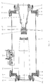
- FIG 3 shows a first embodiment of a three-phase arrangement of a cable sleeve.
- the cable sleeve has a tubular housing 40, which consists of two cup-shaped Housing parts 41 and 42 assembled by means of a flange 43 is.
- the pot bottom 44 and 45 of the two housing parts 41 and 42 is in one piece connected to the pipe sections 41a and 41b.
- the pot bases 44 and 45 have a number of openings 46 and corresponding to the number of phases 47.
- Three cable terminations 48 and 49 are inserted into the openings 46 (in Fig. 3, the third cable end closure is not shown), the attachment of the Cable end closure 48 and 49 made on the pot bottom 44 in the same way becomes like attaching the cable end closure to the insulating housing 19/20 on the plate 15 of the embodiment according to FIG. 1.
- insulating body 50 Through the openings 47 of the other pan bottom 45 insulating body 50 are one Inserted cable connector, which correspond to the insulating body 25 of FIG. 1 or the same.
- the electrically conductive connection of the insulating body 50 to the cable termination 48 is carried out in the same way as the electrically conductive connection of the corresponding parts of Fig. 1st
- a cable connector 51 is drawn inserted; this cable connector is of course also in the insulating body 25 in the embodiment according to FIG. 1 plugged in.
- the cable end closure with the insulating housing 19/20 designed as shown in FIG. 3.
- the insulating housing is in a Way, as described in the above-mentioned documents, a corresponding Cable assembly 52 inserted.
- housing 40 consists of two housing parts 41 and 42 is composed.
- housing 40 in this way form like the tube housing 10.
- the pot bottoms 44 and 45 with the three openings 46 and 47 are formed by a plate which in the same way as the plates 15, 16 by means of the flange rings 11, 12 on the one-piece tube housing 40 are mounted.
- the advantages of single-pole 1 are also in the three-pole version 3 available: The assembly of the arrangement is simple and the length the cable sleeve is also 25% opposite in the three-pole version the known arrangement reduced.
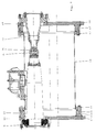
- FIG. 2 shows a further embodiment of a cable sleeve according to the invention Similar to that of FIG. 1, only in a three-pole version.
- a tube housing 60 is provided at both ends with a flange 61, 62.
- On the flange 61 is with the interposition of a ring cylinder 63rd a cover plate 64 fastened by means of screw connections 65, which cover plate 64 a number of openings 66 corresponding to the number of phases has, through which a cable end closure 19, 20 is passed; the cable end closure 3 has the reference numerals 48 and 49.
- each cable end closure is 19/20, in the same way as the 1 provided with the cylindrical contact piece 21, which is formed in the same way as that of FIG. 1 or FIG. 3.
- a cover plate 68 is attached, which also corresponds to the number of phases Number of openings 69, which from the insulating housing 70th is penetrated, which insulating housing attached to the outside of the cover plate 68 is.
- the insulating housing 70 corresponds to the insulating housing 25 of FIGS. 1 and has at its inner end a cylindrical extension 71 which, like the cylindrical one Extension 27 engages in the interior of the cylindrical contact piece.
- the interior is the same as in the embodiment according to FIGS. 1 and 3 of the tube housing 60 filled with insulating gas and the advantages of the single-phase encapsulated Arrangement is also present in the three-phase encapsulated arrangement: the considerably simplified assembly method and a significantly shortened design compared to the known arrangements is shortened by approximately 25%.
Abstract
Description
Die Erfindung betrifft eine Kabelmuffe für eine Kabelverbindung in einer Hochspannungskabelanlage.The invention relates to a cable sleeve for a cable connection in a high-voltage cable system.
Kabelmuffen sind an sich bekannt, siehe Prospekt der Fa. ABB Kabel und Draht
GmbH (ABB Energiekabel GmbH), 68199 Mannheim, Druckschriften-Nr. KUD 1181 D
4.96/1 WDW, ![]()
![]()
Bekannt ist auch ein Kabelendverschluß, dessen eines Ende mit einer Hochspannungskomponente in einer SF6-gasisolierten Hochspannungsanlage verbunden ist und dadurch einen Kabelzu- oder -abgang bildet.Also known is a cable end closure, one end of which is connected to a high-voltage component in an SF 6 gas-insulated high-voltage system and thereby forms a cable inlet or outlet.
Aufgabe der Erfindung ist es, eine Kabelmuffe dieser Art soweit zu verbessern, daß zum einen die Montage vereinfacht ist und zum anderen die Gesamtlänge der Kabelmuffe reduziert werden kann. The object of the invention is to improve a cable sleeve of this type to the extent that on the one hand the assembly is simplified and on the other hand the total length of the cable sleeve can be reduced.
Diese Aufgabe wird erfindungsgemäß durch die Merkmale des Anspruches 1 gelöst.This object is achieved by the features of claim 1.
Erfindungsgemäß also besitzt die Kabelmuffe ein Rohrgehäuse, an deren einem Ende ein handelsüblicher Kabelendverschluß angebracht ist und an deren anderem Ende ein Isolierkörper für einen Kabelstecker angebracht ist, wobei die im Inneren des Gehäuses befindlichen Enden des Kabelendverschlusses und des Isolierkörpers elektrisch leitend miteinander verbunden sind.According to the invention, the cable sleeve has a tubular housing at one end a commercially available cable termination is attached and the other End an insulator for a cable connector is attached, the inside ends of the housing of the cable end closure and the insulating body are electrically connected together.
Zum einen kann bei dieser erfindungsgemäßen Ausführung die Montage der Kabelmuffenenden vereinfacht werden. Zunächst wird, in bekannter Weise, der Kabelendverschluß mit der zugehörigen Platte montiert, an der das Rohrgehäuse befestigt werden kann. Das andere Ende des Rohrgehäuses wird danach mit der anderen Platte verschlossen, an der der Isolierkörper angebracht ist. Bei geeigneter Ausgestaltung der elektrischen Kupplung des Kabelendverschlusses mit dem Isolierkörper entsprechend Anspruch 3 erfolgt die elektrische Verbindung der beiden Komponenten mittels eines Steckvorgangs.On the one hand, in this embodiment according to the invention, the assembly of the cable sleeve ends be simplified. First, in a known manner, the cable end closure mounted with the corresponding plate to which the pipe housing is attached can be. The other end of the tube housing is then connected to the other Closed plate on which the insulating body is attached. With a suitable design the electrical coupling of the cable end closure with the insulating body According to claim 3, the electrical connection of the two components by means of a plugging process.
Bei einer besonders vorteilhaften Ausführung können das Rohrgehäuse sowie der Isolator fabrikseitig zusammenmontiert werden, so daß diese vorgefertigte Einheit einfach an dem Kabelendverschluß befestigt werden kann.In a particularly advantageous embodiment, the tubular housing and the Isolator factory assembled so that this prefabricated unit can be easily attached to the cable end closure.
Dadurch daß die Länge des Isolierkörpers für den Kabelstecker in seiner Bauweise gering ist, kann die Gesamtlänge der Kabelmuffe gegenüber der bekannten Anordnung um ca. 20 bis 30% verkürzt werden. Dies hat auch bei einer Nachrüstung in bestehenden Muffenbauwerken mit begrenztem Platz erhebliche Vorteile.Characterized in that the length of the insulating body for the cable connector in its construction is small, the total length of the cable sleeve compared to the known arrangement can be shortened by approx. 20 to 30%. This also has a retrofit in existing socket structures with limited space considerable advantages.
Das Innere des Rohrgehäuses außerhalb sowohl des Kabelendverschlusses als auch des Isolierkörpers ist in bevorzugter Weise mit einem gasförmigen Isoliermittel gefüllt, welches SF6 sein kann. Es besteht natürlich auch die Möglichkeit, flüssiges Isoliermittel einzubringen oder gegebenenfalls auch aushärtbares Isoliermaterial.The inside of the tube housing outside both the cable end closure and the insulating body is preferably filled with a gaseous insulating agent, which can be SF 6 . There is, of course, also the possibility of introducing liquid insulating material or, if necessary, of curable insulating material.
Diese und weitere vorteilhafte Ausgestaltungen der Erfindung ergeben sich aus den Unteransprüchen. These and other advantageous embodiments of the invention result from the Subclaims.
Es ist selbstverständlich, daß die Kabelmuffe einpolig oder auch dreipolig ausgebildet sein kann. In diesem einpoligen Fall befinden sich innerhalb des Rohrgehäuses ein Kabelendverschluß und ein Isolierkörper. Bei einer mehrpoligen oder mehrphasigen Ausführung sind innerhalb eines Rohrgehäuses eine der Anzahl der Phasen entsprechende Anzahl von Kabelendverschlüssen und Isolierkörpern angeordnet.It goes without saying that the cable sleeve is single-pole or three-pole can be. In this single-pole case, they are inside the tube housing a cable termination and an insulating body. With a multi-pole or multi-phase Execution are one of the number of phases within a pipe housing appropriate number of cable terminations and insulators arranged.
Wenn hier von
Anhand der Zeichnung, in der drei Ausführungsbeispiele der Erfindung dargestellt sind, sollen die Erfindung sowie weitere vorteilhafte Ausgestaltungen und Verbesserungen der Erfindung näher erläutert und beschrieben werden.Based on the drawing, in which three embodiments of the invention are shown are, the invention and other advantageous refinements and improvements the invention are explained and described in more detail.
Es zeigen:
- Fig. 1
- eine Schnittansicht durch eine einpolige und
- Fig. 2 und 3
- je eine Schnittansicht durch je eine dreipolige Kabelmuffe.
- Fig. 1
- a sectional view through a single pole and
- 2 and 3
- A sectional view through a three-pin cable sleeve.
Ein zylindrisches Rohrgehäuse 10 trägt an seinen beiden Enden jeweils eine Flanschleiste
11, 12, an der mittels Schrauben 13, 14 je eine Halteplatte 15, 16 befestigt
ist, die jeweils einen Durchbruch 17, 18 aufweisen. An der einen Halteplatte 15, in
der Zeichnung der linken Halteplatte, ist ein Isoliergehäuse 19 eines handelsüblichen
SF6-Schaltanlageneinbauendverschlusses befestigt, dessen Innenteile in der
Figur 1 nicht dargestellt sind, die aber aus dem oben erwähnten Prospekt der ABB
Energiekabel GmbH, Seite 7, links, bzw. aus dem Prospekt der Fa. ABB Kabel und
Draht GmbH, Mannheim, Druckschriften-Nr. K+D 1048/3D (4.88/1)04,
Der innere Bereich 20 des Isoliergehäuse 19, der sich im Inneren des Rohrgehäuses
befindet, trägt an seinem freien Ende ein zylindrisches Kontaktstück 21, dessen
Innenwandungen zwei Rillen 22 aufweisen, in denen sich Vielfach-Kontaktelemente,
hier Spiralfederkontakte 23 befinden. The
An der anderen Verschlußplatte 16 ist der Flansch 24 eines Isolierkörpers 25 für
einen Kabelstecker mittels Schraubverbindungen 26 befestigt, der ins Innere des
Rohrgehäuses 10 hineinragt und an seinem inneren Ende einen Fortsatz 27 trägt,
der im montierten Zustand ins Innere des Zylinderkontaktes 21 eingreift, wobei er
hierin hineingesteckt werden kann.On the
Die Anordnung gemäß Fig. 1 ist eine transportable Einheit und ist demgemäß mittels
Abdeckplatten 28 und 29 an den offenen Seiten der Isolierkörper 19/20 und 25 verschlossen.1 is a portable unit and is accordingly by means of
Das Rohrgehäuse 10 besitzt außerdem eine Berstschutzeinrichtung 30.The
Zur Montage der Kabelmuffe an Ort und Stelle wird zunächst der Kabelendverschluß
mit dem Isoliergehäuse 19, 20 hergestellt, wie dies aus den oben erwähnten Prospekten
bzw. Druckschriften ersichtlich ist. Danach bestehen mehrere Möglichkeiten:
Zum einen kann an den Flansch 19a des Isoliergehäuses 19/20 die eine Platte 15
angeschlossen werden. An der Platte 15 wird dann das Rohrgehäuse 10 mit den
Schraubenverbindungen 13 befestigt. Danach wird die andere Platte 16 am Rohrgehäuse
10 mit den Schraubenverbindungen 14 festgeschraubt und schlußendlich der
Isolierkörper 25 über den Flansch 24 und die Schraubenverbindungen 26 an der
Platte 16 befestigt, wobei der Fortsatz 27 in das Innere des Zylinderkontaktstückes
21 hineingesteckt wird.To assemble the cable sleeve on the spot, the cable end closure with the
On the one hand, a
Bei einer weiteren Ausführungsform besteht die Möglichkeit, daß die Platte 15, das
Rohrgehäuse 10 und die Platte 16 eine vormontierte Einheit bilden, und bei einer
dritten Ausführungsform kann die vormontierte Einheit aus dem Rohrgehäuse 10,
der Platte 16 und dem daran befestigten Isolierkörper 25 gebildet sein, die nach
Montage des Kabelendverschlusses innerhalb des Isoliergehäuse 19/20 an der
Platte 15 befestigt werden kann.In a further embodiment, there is the possibility that the
Man erkennt, daß der Isolierkörper 25 für einen Kabelstecker deutlich kürzer ist als
der Kabelabschnitt innerhalb des mit Öl gefüllten Gehäuses der an sich bekannten
Kabelmuffe. It can be seen that the
Das Innere des Rohrgehäuses 10 wird mit SF6-Gas als Isoliermittel gefüllt.The inside of the
Die Fig. 3 zeigt eine erste Ausführungsform einer dreiphasigen Anordnung einer Kabelmuffe.3 shows a first embodiment of a three-phase arrangement of a cable sleeve.
Die Kabelmuffe besitzt ein Rohrgehäuse 40, welches aus zwei topfförmig ausgebildeten
Gehäuseteilen 41 und 42 mittels einer Flanschverbindung 43 zusammengesetzt
ist. Der Topfboden 44 bzw. 45 der beiden Gehäuseteile 41 und 42 ist einstückig
mit den Rohrabschnitten 41a und 41b verbunden. Die Topfböden 44 und 45 besitzen
eine der Anzahl der Phasen entsprechende Anzahl von Durchbrüchen 46 und
47. In die Durchbrüche 46 sind drei Kabelendverschlüsse 48 und 49 eingesetzt (in
Fig. 3 ist der dritte Kabelendverschluß nicht dargestellt), wobei die Befestigung des
Kabelendverschlusses 48 bzw. 49 an dem Topfboden 44 in der gleichen Weise vorgenommen
wird wie die Befestigung des Kabelendverschlusses mit dem Isoliergehäuse
19/20 an der Platte 15 der Ausführung nach Fig. 1.The cable sleeve has a
Durch die Durchbrüche 47 des anderen Topfbodens 45 sind Isolierkörper 50 eines
Kabelsteckers eingefügt, die dem Isolierkörper 25 der Fig. 1 entsprechen bzw. gleichen.
Die elektrisch leitende Verbindung des Isolierkörpers 50 mit dem Kabelendverschluß
48 erfolgt in der gleichen Weise wie die elektrisch leitende Verbindung
der entsprechenden Teile der Fig. 1.Through the
In dem Isolierkörper 50 ist ein Kabelstecker 51 eingesteckt gezeichnet; dieser Kabelstecker
wird natürlich auch in den Isolierkörper 25 bei der Ausführung nach Fig. 1
eingesteckt. In gleicher Weise ist der Kabelendverschluß mit dem Isoliergehäuse
19/20 so ausgebildet, wie in der Fig. 3 dargestellt. In das Isoliergehäuse wird in einer
Weise, wie sie in oben genannten Druckschriften beschrieben ist, eine entsprechende
Kabelanordnung 52 eingefügt.In the
In der Fig. 3 ist gezeigt, daß das Gehäuse 40 aus zwei Gehäuseteilen 41 und 42
zusammengesetzt ist. Es besteht natürlich auch die Möglichkeit, das Gehäuse 40 so
auszubilden wie das Rohrgehäuse 10. Unterschiedlich ist dabei, daß die Topfböden
44 und 45 mit den drei Durchbrüchen 46 und 47 durch eine Platte gebildet sind, die
in der gleichen Weise wie die Platten 15, 16 mittels der Flanschringe 11, 12 an dem
einstückigen Rohrgehäuse 40 montiert sind. Die Vorteile, die bei der einpoligen
Ausgestaltung gemäß Fig. 1 gegeben sind, sind auch bei der dreipoligen Ausführung
gemäß Fig. 3 vorhanden: Die Montage der Anordnung ist einfach und die Länge
der Kabelmuffe ist bei der dreipoligen Ausführung ebenfalls um 25% gegenüber
der bekannten Anordnung reduziert.3 shows that the
Die Fig. 2 zeigt eine weitere Ausführungsform einer erfindungsgemäßen Kabelmuffe ähnlich der der Fig. 1, nur in dreipoliger Ausführung.2 shows a further embodiment of a cable sleeve according to the invention Similar to that of FIG. 1, only in a three-pole version.
Ein Rohrgehäuse 60 ist an seinen beiden Enden mit einer Flanschleiste 61, 62 versehen.
An der Flanschleiste 61 ist unter Zwischenfügung eines Ringzylinders 63
eine Abdeckplatte 64 mittels Schraubenverbindungen 65 befestigt, welche Abdeckplatte
64 eine der Anzahl der Phasen entsprechende Anzahl von Durchbrüchen 66
aufweist, durch die je ein Kabelendverschluß 19,20 hindurchgeführt ist; der Kabelendverschluß
besitzt in der Fig. 3 das Bezugszeichen 48 bzw. 49.A
Das freie Ende jedes Kabelendverschlusses 19/20 ist, in gleicher Weise wie bei der
Ausführung gemäß Fig. 1 mit dem zylindrischen Kontaktstück 21 versehen, welches
in der gleichen Weise ausgebildet ist, wie dasjenige der Fig. 1 bzw. der Fig. 3.The free end of each cable end closure is 19/20, in the same way as the
1 provided with the
An der Flanschleiste 62 ist, ebenfalls unter Zwischenfügung einer zylindrischen Leiste
67 eine Abdeckplatte 68 befestigt, die ebenfalls eine der Anzahl der Phasen entsprechende
Anzahl von Durchbrüchen 69 besitzt, die von dem Isoliergehäuse 70
durchgriffen ist, welches Isoliergehäuse an der Außenseite der Abdeckplatte 68 befestigt
ist. Das Isoliergehäuse 70 entspricht dem Isoliergehäuse 25 der Fig. 1 und
besitzt an seinem inneren Ende einen zylindrischen Fortsatz 71, der wie der zylindrische
Fortsatz 27 ins Innere des zylindrischen Kontaktstückes eingreift.On the
In gleicher Weise wie bei der Ausführung gemäß den Figuren 1 und 3 ist das Innere
des Rohrgehäuses 60 mit Isoliergas gefüllt und die Vorteile der einphasig gekapselten
Anordnung sind auch bei der dreiphasig gekapselten Anordnung vorhanden: Die
erheblich vereinfachte Montageweise und eine deutlich verkürzte Bauform, die gegenüber
den bekannten Anordnungen um ca. 25 % verkürzt ist.The interior is the same as in the embodiment according to FIGS. 1 and 3
of the
Claims (8)
Applications Claiming Priority (2)
| Application Number | Priority Date | Filing Date | Title |
|---|---|---|---|
| DE1998105068 DE19805068A1 (en) | 1998-02-10 | 1998-02-10 | Cable sleeve |
| DE19805068 | 1998-02-10 |
Publications (3)
| Publication Number | Publication Date |
|---|---|
| EP0936715A2 true EP0936715A2 (en) | 1999-08-18 |
| EP0936715A3 EP0936715A3 (en) | 2001-05-02 |
| EP0936715B1 EP0936715B1 (en) | 2006-08-30 |
Family
ID=7857064
Family Applications (1)
| Application Number | Title | Priority Date | Filing Date |
|---|---|---|---|
| EP19980123883 Expired - Lifetime EP0936715B1 (en) | 1998-02-10 | 1998-12-16 | Cable sleeve |
Country Status (2)
| Country | Link |
|---|---|
| EP (1) | EP0936715B1 (en) |
| DE (2) | DE19805068A1 (en) |
Cited By (1)
| Publication number | Priority date | Publication date | Assignee | Title |
|---|---|---|---|---|
| WO2017029627A1 (en) * | 2015-08-18 | 2017-02-23 | Chan Lin Fong | A transition joint |
Families Citing this family (1)
| Publication number | Priority date | Publication date | Assignee | Title |
|---|---|---|---|---|
| DE10341302B3 (en) * | 2003-09-02 | 2005-02-17 | Siemens Ag | Cable termination module for pressurized gas insulated switchgear has opposing multi-pole cable termination devices with poles arranged in circular path |
Citations (5)
| Publication number | Priority date | Publication date | Assignee | Title |
|---|---|---|---|---|
| DE2733815A1 (en) * | 1977-07-27 | 1979-02-01 | Felten & Guilleaume Carlswerk | Oil filled cable joint sleeve - in which outer end flange provides sealed connection for both low and high pressure parts |
| DE3822288A1 (en) * | 1988-07-01 | 1990-01-04 | Felten & Guilleaume Energie | Connecting sleeve (bushing) for XLPE (cross-linked polyethylene)insulated high-voltage cables |
| EP0491314A1 (en) * | 1990-12-18 | 1992-06-24 | Gec Alsthom Sa | Bottom arrangement for encapsulation of high voltage equipment in gas insulated, metallic enclosures, especially for cable connections |
| DE4122001C1 (en) * | 1991-07-03 | 1992-07-16 | Felten & Guilleaume Energietechnik Ag, 5000 Koeln, De | Junction sleeve for VPE insulated HV cable - is filled with sulphur hexa:fluoride with joint support provided by hollow conical moulded resin insulator |
| EP0627800A1 (en) * | 1993-06-01 | 1994-12-07 | ABBPATENT GmbH | Metal-clad gas-insulated switch installation with a cable termination |
Family Cites Families (8)
| Publication number | Priority date | Publication date | Assignee | Title |
|---|---|---|---|---|
| US3876820A (en) * | 1974-02-01 | 1975-04-08 | Detroit Edison Co | Pressurized fluid insulation for high voltage cable |
| DE7822838U1 (en) * | 1978-07-29 | 1978-11-09 | Felten & Guilleaume Carlswerk Ag, 5000 Koeln | Connector for connecting two cable ends |
| NL8901138A (en) * | 1989-05-03 | 1990-12-03 | Nkf Kabel Bv | PLUG-IN CONNECTION FOR HIGH-VOLTAGE PLASTIC CABLES. |
| DE4009358C2 (en) * | 1990-03-23 | 1997-05-15 | Sachsenwerk Ag | Socket |
| DE4139100C1 (en) * | 1991-11-28 | 1993-01-07 | Karl Pfisterer Elektrotechnische Spezialartikel Gmbh & Co Kg, 7000 Stuttgart, De | Plug and socket appts. - has elastic deformable damping piece(s) radially tensioned against contact support as well as socket when coupled together |
| DE4403571C1 (en) * | 1994-02-05 | 1995-05-18 | Pfisterer Elektrotech Karl | Coupling for plastic insulated high voltage cables has screw terminal block within housing that has inner and outer sections of that shrouds connection. |
| DE19508973C2 (en) * | 1995-03-13 | 2002-04-04 | Abb Patent Gmbh | Cable set with a pressure slide enclosing a cable like a sleeve |
| DE19508975A1 (en) * | 1995-03-13 | 1996-09-19 | Abb Patent Gmbh | Device for exerting pressure on an elastic field control cone |
-
1998
- 1998-02-10 DE DE1998105068 patent/DE19805068A1/en not_active Ceased
- 1998-12-16 DE DE59813702T patent/DE59813702D1/en not_active Expired - Lifetime
- 1998-12-16 EP EP19980123883 patent/EP0936715B1/en not_active Expired - Lifetime
Patent Citations (5)
| Publication number | Priority date | Publication date | Assignee | Title |
|---|---|---|---|---|
| DE2733815A1 (en) * | 1977-07-27 | 1979-02-01 | Felten & Guilleaume Carlswerk | Oil filled cable joint sleeve - in which outer end flange provides sealed connection for both low and high pressure parts |
| DE3822288A1 (en) * | 1988-07-01 | 1990-01-04 | Felten & Guilleaume Energie | Connecting sleeve (bushing) for XLPE (cross-linked polyethylene)insulated high-voltage cables |
| EP0491314A1 (en) * | 1990-12-18 | 1992-06-24 | Gec Alsthom Sa | Bottom arrangement for encapsulation of high voltage equipment in gas insulated, metallic enclosures, especially for cable connections |
| DE4122001C1 (en) * | 1991-07-03 | 1992-07-16 | Felten & Guilleaume Energietechnik Ag, 5000 Koeln, De | Junction sleeve for VPE insulated HV cable - is filled with sulphur hexa:fluoride with joint support provided by hollow conical moulded resin insulator |
| EP0627800A1 (en) * | 1993-06-01 | 1994-12-07 | ABBPATENT GmbH | Metal-clad gas-insulated switch installation with a cable termination |
Cited By (1)
| Publication number | Priority date | Publication date | Assignee | Title |
|---|---|---|---|---|
| WO2017029627A1 (en) * | 2015-08-18 | 2017-02-23 | Chan Lin Fong | A transition joint |
Also Published As
| Publication number | Publication date |
|---|---|
| EP0936715B1 (en) | 2006-08-30 |
| DE59813702D1 (en) | 2006-10-12 |
| EP0936715A3 (en) | 2001-05-02 |
| DE19805068A1 (en) | 1999-08-12 |
Similar Documents
| Publication | Publication Date | Title |
|---|---|---|
| DE19519301A1 (en) | Disconnector for a metal-enclosed gas-insulated high-voltage switchgear | |
| DE4412784A1 (en) | Current and voltage sensor for a high-voltage control panel and high-voltage control panel with such a current and voltage sensor | |
| DE3313192C2 (en) | ||
| DE2924430A1 (en) | METAL-ENCLOSED, SF DEEP 6 GAS INSULATED SWITCHGEAR | |
| WO2007051319A1 (en) | High-voltage circuit breaker and breaker arrangement | |
| EP1249910B1 (en) | High voltage switch for a gas insulated switching installation | |
| EP1149445A1 (en) | Multiphase encapsulated high-voltage switchgear for outdoor use | |
| WO1998008284A1 (en) | Encapsulated gas isolated high voltage installation with a partitioned connector component | |
| DE2123549A1 (en) | Power supply device | |
| DE3521945A1 (en) | DISCONNECTOR FOR A METAL-ENCLOSED, PRESSURE-GAS INSULATED HIGH-VOLTAGE SWITCHGEAR | |
| EP0875971B1 (en) | High voltage switchgear | |
| DE102006001237A1 (en) | Three-phase insulated high voltage switch gear, has supporting unit with insulating connector provided between circuit breaker and bus bar region, where connector is formed such that circuit breaker is stabilized in its position | |
| EP0936715B1 (en) | Cable sleeve | |
| DE19641391C1 (en) | Hybrid type high-voltage switchgear | |
| DE4438776C1 (en) | Metal-enclosed electrical high-voltage switchgear with a circuit breaker | |
| DE19845006C1 (en) | Overhead cable connector for MV electrical network cables has corresponding cable wire ends enclosed by common connector and field control body contained within outer insulator | |
| DE3318229A1 (en) | HOUSING FOR HIGH VOLTAGE SWITCHES | |
| DE102016207292A1 (en) | Electric protection device | |
| EP0718942B1 (en) | High voltage installation | |
| DE10341302B3 (en) | Cable termination module for pressurized gas insulated switchgear has opposing multi-pole cable termination devices with poles arranged in circular path | |
| DE19530163C2 (en) | High voltage leadout and feedthrough arrangement for transformers or choke coils | |
| DE1170501C2 (en) | Metal-enclosed high-voltage switchgear | |
| DE102010004971A1 (en) | Current transformer module for high or medium voltage switchgear, has cabinet with common gas space for receiving isolation gas of nominal guards and single phase region for locating current transformers | |
| DE2847376C2 (en) | Single or multi-pole disconnector arrangement for encapsulated switchgear | |
| WO2006084401A1 (en) | Switch terminal |
Legal Events
| Date | Code | Title | Description |
|---|---|---|---|
| PUAI | Public reference made under article 153(3) epc to a published international application that has entered the european phase |
Free format text: ORIGINAL CODE: 0009012 |
|
| AK | Designated contracting states |
Kind code of ref document: A2 Designated state(s): BE CH DE FR GB IT LI NL SE |
|
| AX | Request for extension of the european patent |
Free format text: AL;LT;LV;MK;RO;SI |
|
| PUAL | Search report despatched |
Free format text: ORIGINAL CODE: 0009013 |
|
| AK | Designated contracting states |
Kind code of ref document: A3 Designated state(s): AT BE CH CY DE DK ES FI FR GB GR IE IT LI LU MC NL PT SE |
|
| AX | Request for extension of the european patent |
Free format text: AL;LT;LV;MK;RO;SI |
|
| 17P | Request for examination filed |
Effective date: 20010627 |
|
| RAP1 | Party data changed (applicant data changed or rights of an application transferred) |
Owner name: ABB PATENT GMBH |
|
| AKX | Designation fees paid |
Free format text: BE CH DE FR GB IT LI NL SE |
|
| GRAP | Despatch of communication of intention to grant a patent |
Free format text: ORIGINAL CODE: EPIDOSNIGR1 |
|
| GRAS | Grant fee paid |
Free format text: ORIGINAL CODE: EPIDOSNIGR3 |
|
| GRAA | (expected) grant |
Free format text: ORIGINAL CODE: 0009210 |
|
| AK | Designated contracting states |
Kind code of ref document: B1 Designated state(s): BE CH DE FR GB IT LI NL SE |
|
| PG25 | Lapsed in a contracting state [announced via postgrant information from national office to epo] |
Ref country code: NL Free format text: LAPSE BECAUSE OF FAILURE TO SUBMIT A TRANSLATION OF THE DESCRIPTION OR TO PAY THE FEE WITHIN THE PRESCRIBED TIME-LIMIT Effective date: 20060830 |
|
| REG | Reference to a national code |
Ref country code: GB Ref legal event code: FG4D Free format text: NOT ENGLISH |
|
| REG | Reference to a national code |
Ref country code: CH Ref legal event code: EP |
|
| REF | Corresponds to: |
Ref document number: 59813702 Country of ref document: DE Date of ref document: 20061012 Kind code of ref document: P |
|
| GBT | Gb: translation of ep patent filed (gb section 77(6)(a)/1977) |
Effective date: 20061004 |
|
| PG25 | Lapsed in a contracting state [announced via postgrant information from national office to epo] |
Ref country code: SE Free format text: LAPSE BECAUSE OF FAILURE TO SUBMIT A TRANSLATION OF THE DESCRIPTION OR TO PAY THE FEE WITHIN THE PRESCRIBED TIME-LIMIT Effective date: 20061130 |
|
| PG25 | Lapsed in a contracting state [announced via postgrant information from national office to epo] |
Ref country code: BE Free format text: LAPSE BECAUSE OF NON-PAYMENT OF DUE FEES Effective date: 20061231 |
|
| NLV1 | Nl: lapsed or annulled due to failure to fulfill the requirements of art. 29p and 29m of the patents act | ||
| PLBE | No opposition filed within time limit |
Free format text: ORIGINAL CODE: 0009261 |
|
| STAA | Information on the status of an ep patent application or granted ep patent |
Free format text: STATUS: NO OPPOSITION FILED WITHIN TIME LIMIT |
|
| 26N | No opposition filed |
Effective date: 20070531 |
|
| BERE | Be: lapsed |
Owner name: ABB PATENT G.M.B.H. Effective date: 20061231 |
|
| REG | Reference to a national code |
Ref country code: GB Ref legal event code: 732E Free format text: REGISTERED BETWEEN 20101216 AND 20101222 |
|
| REG | Reference to a national code |
Ref country code: FR Ref legal event code: TP |
|
| REG | Reference to a national code |
Ref country code: FR Ref legal event code: PLFP Year of fee payment: 18 |
|
| REG | Reference to a national code |
Ref country code: FR Ref legal event code: PLFP Year of fee payment: 19 |
|
| REG | Reference to a national code |
Ref country code: DE Ref legal event code: R082 Ref document number: 59813702 Country of ref document: DE Representative=s name: REBLE KLOSE SCHMITT PARTNERSCHAFTSGESELLSCHAFT, DE |
|
| REG | Reference to a national code |
Ref country code: FR Ref legal event code: PLFP Year of fee payment: 20 |
|
| PGFP | Annual fee paid to national office [announced via postgrant information from national office to epo] |
Ref country code: FR Payment date: 20171219 Year of fee payment: 20 |
|
| PGFP | Annual fee paid to national office [announced via postgrant information from national office to epo] |
Ref country code: CH Payment date: 20171221 Year of fee payment: 20 Ref country code: GB Payment date: 20171221 Year of fee payment: 20 Ref country code: IT Payment date: 20171218 Year of fee payment: 20 |
|
| PGFP | Annual fee paid to national office [announced via postgrant information from national office to epo] |
Ref country code: DE Payment date: 20171231 Year of fee payment: 20 |
|
| REG | Reference to a national code |
Ref country code: DE Ref legal event code: R071 Ref document number: 59813702 Country of ref document: DE |
|
| REG | Reference to a national code |
Ref country code: CH Ref legal event code: PL |
|
| REG | Reference to a national code |
Ref country code: GB Ref legal event code: PE20 Expiry date: 20181215 |
|
| PG25 | Lapsed in a contracting state [announced via postgrant information from national office to epo] |
Ref country code: GB Free format text: LAPSE BECAUSE OF EXPIRATION OF PROTECTION Effective date: 20181215 |