Technical Field
The present invention relate to a carbonaceous material for a negative electrode
as a preferred material for the negative electrode of a non-aqueous secondary battery
which has excellent characteristics as a power source for a small-size and light-weight
electric apparatuses and an electric automobile and a carbonaceous precursor, and
more particularly to a non-aqueous secondary battery containing the carbonaceous
material for a negative electrode.
Background Art
In recent years, wide use of portable apparatuses, such as video cameras,
portable telephones and portable personal computers, raises a need for secondary
batteries to be employed in place of primary batteries because the secondary batteries
can repetitively be used. In particular, non-aqueous secondary batteries receive
attention, the non-aqueous secondary battery containing a carbonaceous material to
serves as a material for the negative electrode, a composite oxide containing lithium
to serves as a material for the positive electrode and organic solvent to serve as an
electrolyte.
As materials to serve as an active material for the negative electrode, a
soft-carbon type carbonaceous material, such as cokes, has been suggested in Japanese
Patent Publication No. 4-24831 and a hard-carbon type carbonaceous material has
been suggested in Japanese Patent Laid-Open No. 3-25053. As an active material for
the positive electrode, LiMO2 (where M is Co or Ni) disclosed in Japanese Patent
Laid-Open No. 63-135099 has been suggested.
However, a non-aqueous secondary battery containing the conventional
carbonaceous material as the active material for the negative electrode, having
excellent cycle lifetime and safety, is required to furthermore raise the energy density.
The reason for this lies in that the power consumption in the portable apparatus has
been enlarged and a longer operating time permitted by one charging operation has
therefore been required.
To achieve this, it might be considered to employ a countermeasure of raising
a density of filling the active material on the surface of the electrode. Another method
may be employed in which a large quantity of materials of the electrode is packed in
the battery can. However, the foregoing countermeasures have limitations. The active
materials for the negative electrodes cannot easily raise the energy density because the
soft-carbon type carbonaceous material suffers from a small capacity in spite of a high
true density. The hard-carbon type carbonaceous material suffers from a low true
density in spite of a large capacity.
Disclosure of the Invention
An object of the present invention is to provide a carbonaceous material for a
negative electrode having a large capacity per unit volume and a manufacturing
method therefor. Another object of the present invention is to provide a non-aqueous
secondary battery having excellent cycle lifetime and safety and exhibiting a high
energy density.
To achieve the above-mentioned objects, the inventors of the present invention
have energetically performed investigations, resulting in detection of the following
facts.
The carbonaceous material to form the negative electrode of the non-aqueous
secondary battery includes crystalline portions formed by laminating several
fragments. The fragments are structural units in each of which benzene rings are
planarly connected to one another and each of which has a size of about 10Å.
Moreover, the carbonaceous material includes amorphous portions in each of which
any regular lamination is not observed. The crystalline portions, in each of which
carbon atoms are densely packed, have densities higher than those of the amorphous
portions. On the other hand, the amorphous portions have low densities and include
many spaces as compared with the crystalline portions. Hydrogen atoms
covalent-bonds to a portion of carbon atoms at the ends of the fragments.
When elements, such as lithium, are doped electrochemically, the elements,
such as lithium, are occluded in the three following types of sites of the carbonaceous
material having the above-mentioned structure. Thus, it can be considered that a high
electrochemical capacity is realized.
Therefore, the carbonaceous material for a negative electrode according to the
present invention is arranged to indicate the total volume of spaces in the
carbonaceous material with a true density and an X-ray diffraction pattern. As indexes
indicating the crystallinity of the carbonaceous material, intervals between plane (002)
and the thickness of crystallites are employed. Moreover, the concentration of
hydrogen contained in the carbonaceous material is used.
That is, the carbonaceous material for a negative electrode according to the
present invention has a true density of 1.65 g/cc to 1.85 g/cc. The content of hydrogen
with respect to carbon is 0.01 to 0.15 in terms of atomic ratio. The intervals of the
planes (002) are 3.45Å to 3.55Å. The thickness of the crystallite is 12.0Å to 20.0Å.
An assumption is made that an area enclosed by a base line which is a common tangent
line connecting minimal values on the two sides of a (002) diffraction line in a
scattered X-ray curve and the (002) diffraction line is S1. Another assumption is made
that an area enclosed by a scattered X-ray curve having a diffraction angle 2 of 4° or
more and positioned in lower angle portions as compared with the (002) diffraction
line and the base line is S0. In the foregoing case, an area ratio of S0 with respect to
S1 is 0.4 to 2.0.
A method of manufacturing the carbonaceous material for a negative electrode
comprises the steps of subjecting the carbonaceous raw material containing γ resin by
0.5 wt% to 30 wt% to an oxidizing process to obtain a carbonaceous precursor of an
oxidation product having a content of oxygen with respect to carbon which is 0.01 to
0.2; and calcinating the oxidation product in an inactive atmosphere.
The inventors of the present invention have found a fact that provision of a
carbonaceous precursor, which has a self-sintering characteristic and which is changed
to a carbon material having a large capacity in the following calcinating process,
enables the carbonaceous material for a negative electrode having excellent
characteristics to be obtained. The carbonaceous precursor according to the present
invention is prepared after which the calcinating process is performed so that the
negative electrode is formed without a mix, such as a binder. Thus, the density of the
active materials in the negative electrode can be raised so that a non-aqueous
secondary battery having a high energy density is obtained.
The carbonaceous precursor according to the present invention is a precursor
of an active material for a negative electrode of a non-aqueous secondary battery
comprising a negative electrode, a positive electrode and a non-aqueous electrolyte,
wherein a content of carbon is 80 wt% to 95 wt%, an element ratio O/C of oxygen and
carbon is 0.01 to 0.2 and a quantity of γ resin is 0.5 wt% to 5 wt%.
A non-aqueous secondary battery according to the present invention comprises
a positive electrode, a negative electrode mainly composed of a carbonaceous material
and a non-aqueous electrolyte, wherein the carbonaceous material is used to form the
negative electrode. Sine the carbonaceous material for a negative electrode has a
multiplicity of sites which permit doping/dedoping of lithium, the capacity per unit
volume can be enlarged. Thus, a high energy density can be realized.
Brief Description of the Drawings
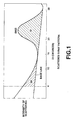
FIG. 1 is a graph showing a scattered X-ray pattern of a carbonaceous material
for a negative electrode according to the present invention;
FIG. 2 is a graph showing a scattered X-ray pattern of the carbonaceous
material for a negative electrode obtained in examples;
FIG. 3 is a cross sectional view showing the structure of a coin-type secondary
battery according to the present invention; and
FIG. 4 is a cross sectional view showing the structure of a cell for measuring
charge/discharge capacity.
Best Mode for Carrying Out the Invention
The present invention will now be described.
The carbonaceous precursor according to the present invention is, in the
following process, calcinated in an inactive atmosphere so as to be changed to a
practical carbon material suitable to serve as an active material for the negative
electrode of a non-aqueous secondary battery. To obtain a sintered negative electrode
composed of an active material and a collector, which is employed if necessary,
without use of a mixes, such as a binder and a conductive material, a method may be
employed by which the powdered carbonaceous precursor is applied with a pressure
by using a die or the like to form a compact, followed by performing a calcinating
process. If a collector or a lead wire is necessary for the negative electrode, the
foregoing elements and the carbonaceous precursor may collectively be molded and
sintered. The carbon material obtained by calcinating the carbonaceous precursor
according to the present invention may be used as an active material for a negative
electrode which is manufactured by binding powder with a binder or the like.
A main portion of oxygen contained in the carbonaceous precursor is gasified
in the calcinating process and thus oxygen is lost. However, oxygen is an important
factor for introducing the obtained carbon material into the amorphous portions to
increase spaces which are able to occlude lithium or the like. It is preferable that the
quantity of oxygen is, in terms of the atomic ratio O/C of oxygen and carbon, 0.01 to
0.2, more preferably 0.01 to 0.1 and most preferably 0.04 to 0.06. If the quantity of
oxygen is too small, the amorphous portions in a sufficient quantity cannot be included
in the carbon material which is obtained in the following calcinating process. Thus,
the capacity is undesirably reduced. If the quantity of oxygen is too large, a
multiplicity of spaces are created in the carbon material which is obtained in the
following calcinating process. Therefore, the density of the carbon material is
lowered. In the foregoing case, the object of the present invention to raise the density
of the negative electrode cannot be achieved.
The quantity of an organic material which is contained in the carbonaceous
precursor and which can be dissolved by toluene, that is, the quantity of γ resin or the
quantity of a caking component represented by a weight reduction ratio observed
during raising of the temperature of the carbonaceous precursor to 600°C in the
inactive atmosphere is an important factor which determines molding of the
carbonaceous precursor and sintering. The caking component is an organic compound
having a low molecular weight and serving to connect particles to one another in the
molding process. In the sintering process, the caking component is spontaneously
carbonized during the sintering process to permit sintering. That is, if the caking
component is too small, there arises a problem in that force to connect particles to one
another is too small to obtain a compact or the strength of the compact is too small to
withstand handling. In the sintering process, the sintering force is too small to obtain
a sintered compact having sufficiently large strength to serve as an electrode. If the
quantity of the caking component is too large, sintering excessively proceeds in the
calcinating process. As a result, the porosity of the obtained sintered compact is too
low to form the negative electrode. That is, it is preferable that the quantity of γ resin
is 0.5 wt% to 5 wt%, more preferably 1 wt% oxygen 3 wt%. The weight reduction
ratio which is observed until the temperature is raised to 600°C is 5 wt% to 12 wt%,
preferably 7 wt% to 12 wt%.
The carbonaceous precursor according to the present invention is converted into
a material substantially composed of carbon by calcination so as to be used.
Therefore, the content of carbon in the carbonaceous precursor is 80 wt% to 95 wt%,
preferably 87 wt% to 93 wt%.
A method of obtaining the carbonaceous precursor according to the present
invention is not limited particularly. A specific method will now be described. The
carbonaceous precursor according to the present invention can be obtained by
oxidizing graphitizing carbon precursor, such as petroleum pitch or coal pitch, and by
performing a heating process in an inactive atmosphere if necessary. When the
graphitizing carbon precursor, such as pitch, is oxidized, it is preferable that the
quantity of γ resin in the carbonaceous precursor is 0.5 wt% to 30 wt%, more
preferably 1 wt% to 30 wt%, and most preferably 3 wt% to 26 wt%. If the quantity
of the γ resin is too small, the quantity of the caking component in the carbonaceous
precursor which can be obtained by the oxidizing process or the heating process
cannot be adjusted to satisfy a required range. If the quantity of the γ resin is too
large, the softening point of the raw material is lowered. Thus, the temperatures in the
oxidizing process and the heating process are limited disadvantageously for
performing the foregoing processes.
The method of the oxidizing process is not limited particularly if the employed
method enables required quantities of oxygen and caking component to be obtained.
The specific methods are exemplified by oxidation using oxygen or air, oxidation
using sulfuric acid, nitric acid or hydrogen peroxide and oxidation using NO2, NOx,
SO2, SCx, halogen or ozone. Also the oxidation method may be performed by a wet
process or a dry process.
It is preferable that the dry oxidation process using air is employed to easily
complete the process. Specifically, any one of the foregoing method may be
employed: a still standing method in which powder of the carbonaceous precursor is
introduced into a container after which heating is performed; a stirring method in
which powder of the carbonaceous precursor is heated in an air flow or in air blow
while powder of the carbonaceous precursor is being stirred; and a method in which
a fluidized bed formed by a gas flow or vibrations is used. The still standing method
encounters frequent runaway of reactions owning to accumulation of heat generated
in the oxidizing reactions. Thus, control cannot easily be performed. The fluidized
bed oxidizing method encounters rapid proceeding of reactions. Also the foregoing
method cannot easily be controlled. On the other hand, the stirring oxidizing method
requires only simple facilities and free from frequent runaway caused from
accumulated heat and reactions in excessively short time. Thus, an industrial
advantage can be realized. It is preferable that the temperatures in the oxidizing
process using air satisfies a range from 100°C to 400°C, more preferably a range from
200°C to 350°C. If the oxidizing temperature is too low, oxidation does not proceed.
If the oxidizing temperature is too high, the temperature of a good which must be
processed encounters runaway owning to heat generated in the oxidizing process.
Thus, the control cannot easily be performed. What is worse, the caking component
in an appropriate quantity cannot be maintained. Also the oxidizing time is not limited
particularly. If the oxidizing temperature is high, the processing time can be
shortened. If the oxidizing temperature is low, the processing time is elongated.
When the quantity of oxygen and the quantity of caking component cannot
easily be controlled by the oxidizing process, a heating process which is performed in
an inactive atmosphere (that is, in anon-oxidizing atmosphere) may be added after the
oxidizing process has been continued until a predetermined quantity of oxygen is
obtained. When the heating process is performed, only the caking component is
adjusted without expelling oxygen taken in the oxidizing process which is the previous
process. Thus, a method can be employed in which the quantity of oxygen and the
caking component are independently controlled in independent processes. Thus, the
process for improving the stability of the quality can satisfactorily be performed. It
is preferable that the heating process is performed in an inactive atmosphere. The
temperature in the heating process is selected from a range from 200°C to 450 °C. It
is preferable that the temperature is 250°C to 400°C. If the temperature in the heating
process is too low, an excess portion of the caking component cannot be expelled. If
the temperature is too high, controllability cannot be improved. What is worse, oxygen
undesirably starts desorbing.
Since the oxidation reaction is a solid-gas reaction, the particle size of the
carbonaceous precursor which is subjected to the oxidation process is selected from
a range from 1 µm to 1 mm in consideration of dispersion of oxygen in solid. It is
preferable that the particle size is 200 µm or smaller, more preferably 5 µm to 60 µm
and most preferably 10 µm to 40 µm. When pulverization is required to obtain a
carbonaceous raw material having the above-mentioned particle size, a usual
pulverizing method may be employed.
The carbonaceous material for a negative electrode according to the present
invention has a true density of 1.65 g/cc to 1.85 g/cc. The content of hydrogen with
respect to carbon is 0.01 to 0.15 in terms of atomic ratio H/C. The intervals d002 of the
planes (002) are 3.45Å to 3.55Å. The thickness Lc of the crystallite is 12.0Å to 20.0Å.
As shown in FIG. 1, an assumption is made that an area enclosed by a base line which
is a common tangent line connecting minimal values (which appear adjacent to 2 =
15° and 30°) on the two sides of a (002) diffraction line in a scattered X-ray curve and
the (002) diffraction line is S1. Another assumption is made that an area enclosed by
a scattered X-ray curve having a diffraction angle 2 of 4° or more and positioned in
lower angle portions as compared with the (002) diffraction line and the base line is
S0. In the foregoing case, an area ratio S0/S1 is 0.4 to 2.0. The range of the area ratio
S0/S1 is an intermediate value between that of the soft-carbon type carbonaceous
material and that of the hard-carbon type carbonaceous material.
The carbonaceous material for a negative electrode has a determined true
density and scattered X-ray curve (the area ratio S0/S1) as indexes indicting the total
volume of spaces in the carbonaceous material. As the indexes indicating the
crystallinity of the carbonaceous material, the intervals of (002) planes and the
thickness of the crystalline are defined. Moreover, the concentration of hydrogen
contained in the carbonaceous material is determined.
That is, the true density of the carbonaceous material is an important index
indicating the total volume of spaces included in the carbonaceous material, that is, the
amorphous portions and as well as a basic property which determines the density of
active material in the electrode.
If the true density is too high, the amorphous portions are decreased and a
structure similar to a graphite structure is undesirably formed. If the true density is too
low, that is, if the carbonaceous material has a large amorphous portions and a
multiplicity of spaces, occlusion into the spaces is enhanced and the capacity per unit
weight is enlarged. However, the density of the electrode is undesirably lowered.
Therefore, it is preferable that the true density of the carbonaceous material according
to the present invention is 1.65 g/cc to 1.85 g/cc, more preferably 1.71 g/cc to 1.79
g/cc. In the above-mentioned range, a battery in which the two factors are
satisfactorily balanced and which enables a large capacity per unit volume can be
obtained.
The area ratio S0/S1 obtainable from the scattered X-ray curve of the
carbonaceous material according to the present invention is an index indicating the
size and content of spaces which enlarge the capacity of the carbonaceous material.
The spaces included in the carbonaceous material create a condensation and
rarefaction structure of electrons, causing intense scattering to be shown in small angle
regions of the X-ray diffraction pattern. The area S0 corresponds to spaces having a
diffraction angle 2 of 4° to 15°, that is, the condensation and rarefaction period of
electrons satisfies a range from about 22Å to about 6Å (= wavelength λ of
X-ray/2sin()). The foregoing spaces having the specific sizes are important factors.
The area ratio S0/S1 is standardization of a content (S0) of the spaces having the
specific sizes and contributing to the capacity with a content (S1) of the crystalline
portions.
If the area ratio S0/S1 is too low, spaces contributing to the capacity are
undesirably reduced. If the area ratio S0/S1 is too high, the density is lowered and the
capacity per unit volume is undesirably reduced. Therefore, it is preferable that the
area ratio S0/S1 is 0.4 to 2.0, more preferably 0.5 to 2.0, and most preferably 0.5 to
1.5.
The intervals d002 between (002) planes of the carbonaceous material according
to the present invention and the thickness Lc of the crystalline are indexes indicating
the crystallinity of the crystalline portions. The intervals d002 between (002) planes and
the thickness Lc of the crystalline are important factors to create spaces having
required sizes as well as the sizes of the fragments.
If the intervals d002 between (002) planes or the thickness Lc of the crystalline
is too large, large spaces which do not contribute the capacity are increased. Thus, the
capacity is undesirably reduced and decomposition of the electrolyte is undesirably
enhanced. If the intervals d002 between (002) planes or the thickness Lc of the
crystalline is too small, small spaces which do not contribute to the capacity are
increased. Thus, the capacity is undesirably reduced and the density of the electrode
is undesirably lowered. Therefore, it is preferable that the intervals d002 between (002)
planes is 3.45Å to 3.55Å, more preferably 3.45Å to 3.52Å. It is preferable that the
thickness Lc of the crystalline is 12.0Å to 20.0Å, more preferably 15Å to 20Å, and
most preferably 17Å to 19Å.
The atomic ratio H/C of the carbonaceous material according to the present
invention is an index for determining the concentration of hydrogen contained in the
carbonaceous material and a capacity realized by lithium or the like which is occluded
owning to mutual action with carbon atoms bounded with hydrogen atoms.
A carbonaceous material having a high atomic ratio H/C encounters impractical
enlargement of the irreversible capacity in a first charging/discharging operation in
spite of enlargement of the capacity. Therefore, it is preferable that the atomic ratio
H/C is 0.01 to 0.15, more preferably 0.01 to 0.10.
A method of obtaining the carbonaceous material for a negative electrode is not
limited particularly. For example, a method in which the above-mentioned
carbonaceous precursor is calcinated may be employed.
When the carbonaceous precursor is calcinated in an inactive atmosphere, a
required carbonaceous material for a negative electrode can be obtained. The inactive
atmosphere is an atmosphere filled with inactive gas, such as nitrogen or argon, or an
atmosphere, such as a vacuum atmosphere, the pressure of which has been lowered.
The calcinating process in the inactive atmosphere may be performed by an
industrially usual method and therefore the method is not limited particularly.
It is preferable that the calcinating temperature satisfies 800°C to 1400 °C, more
preferably 900°C to 1100°C. The calcinating time is industrially advantageous when
the process is performed for 1 hour to 3 hours in the above-mentioned temperature
range.
The thus-obtained carbonaceous material has the true density of 1.65 g/cc to
1.85 g/cc. The content of hydrogen with respect to carbon is 0.01 to 0.15 in terms of
atomic ratio H/C. The intervals d002 between (002) planes in the X-ray diffraction
measurement is 3.45Å to 3.55Å. The thickness Lc of the crystalline is 12.0Å to 20.0Å.
The area ratio S0/S1 of S0 with respect to S1 is 0.4 to 2.0.
When the above-mentioned parameters of the carbonaceous material for a
negative electrode are optimized, a multiplicity of sites which permit doping/dedoping
lithium can be formed. As a result, the foregoing carbonaceous material can be used
as well as a sintered body. Thus, the capacity per unit volume can be enlarged.
To optimize the foregoing parameters, it is effective to use a carbonaceous raw
material in which γ resin is contained by 0.5 wt% to 30 wt%, followed by oxidizing the
carbonaceous raw material to obtain an oxidation product having an atomic ratio O/C
of 0.01 to 0.2, and followed by calcinating the oxidation product.
The non-aqueous secondary battery according to the present invention
comprises a negative electrode mainly composed of the foregoing carbonaceous
material for a negative electrode, a positive electrode and a non-aqueous electrolyte.
Note that movement speed of the element, such as lithium or ions of the element
in a solid made of the carbonaceous material is lowest in the crystalline portions each
having a dense structure. Therefore, the structure of the electrode must be formed into
a porous structure to enlarge the contact between the active material for the electrode
and the electrolyte. If the diameters of pores are too small, penetration of the
electrolyte is inhibited, causing the capacity to be reduced. Therefore, it is preferable
that the average particle size of the carbonaceous material which constitutes the
negative electrode is 1 µm to 100 µm, more preferably 5 µm to 50 µm.
It is optimum that the carbonaceous material obtained in the form of the
sintered body is as it is used as the electrode. The carbonaceous material may be
pulverized so as to be mixed with the binder and so forth and used as a mix for the
electrode. When the sintered body is used as the electrode, a structure may be
employed, if necessary, in which a collector and the sintered body are integrated.
The active material for forming the positive electrode of the non-aqueous
secondary battery according to the present invention my be any one of conventional
materials. Therefore, the material is not limited particularly. Specifically, any one of
the following materials may be employed: LiFeO2, LiCoO2, LiNiO2, LiMn2O4, their
non-stoichiometric compounds, MnO2, TiS2, FeS2, Nb3S4, Mo3S4, CoS2, V2O5, P2O5,
CrO3, V3O3, TeO2 or GeO2.
The electrolyte may be any one of conventional electrolyte if the employed
electrolyte is prepared by dissolving the electrolyte in organic solvent. Therefore, the
material is not limited particularly. The organic solvent may be ester, such as
propylene carbonate, ethylene carbonate or γ-butylolactone; ether, such as
diethylether, tetrahydrofuran, substituted tetrahydrofuran, dioxolane, pyran, their
derivatives, dimethoxyethane or diethoxyethane; 3-substituent-2-oxasolidinone, such
as 3-methyl-2-oxosolidinone; sulfolane; methylsulfolane; acetonitrile; or propionitrile.
Any one of the foregoing materials may be employed or their mixture may be
employed. The electrolyte may be any one of the following materials: lithium
borofluoride; phosphorus borofluoride; lithium chloride acuminate; lithium halide; and
trifluoromethane lithium sulfonate.
The structure of the battery may be a structure formed by spirally winding the
positive electrode and the negative electrode through a separator or a structure formed
by laminating the positive electrode and the negative electrode through the separator.
The present invention will specifically be described in accordance with results
of experiments.
〈Preparation of Carbonaceous Precursor and Evaluation of the Same〉
Comparative Example 1
Coal tar pitch was heat-treated so that the volatile component (VM) was made
to be 22.1 wt%, the quantity of γ resin was 25.0 wt% and O/C was made to be 0.009
(atomic ratio). Then, heat treatment was performed at 280°C for one hour while
mechanical energy being imparted in the presence of air so that a carbonaceous raw
material was obtained in which the quantity of γ resin was 5.2 wt%, the content of
carbon was 94.0 wt%, O/C was 0.012 (atomic ratio) and the quantity of caking
component was 14.8 wt%. Pulverization was performed to make the median diameter
to be 18 µm. Thus, powder of the carbonaceous raw material subjected no process
was molded and calcinated. Results were shown in Table 1.
The contents of carbon and hydrogen, the particle size, a method of measuring
γ resin and methods of evaluating moldability, a sintering characteristic and a battery
characteristic were as follows and commonly applied to the following comparative
examples and examples.
The contents of carbon and hydrogen were measured by "CHN meter 240C"
manufactured by Parkin Elmer. The atomic ratio H/C between hydrogen and carbon
was calculated by using atomic weights of the elements obtained from the weight ratio
between carbon and hydrogen. The element ratio O/C of oxygen and carbon was
calculated by using their atomic weights obtained from the weight contents of carbon
and oxygen. The content of oxygen was measured by using an oxygen and nitrogen
analyzing apparatus (TC-436) manufactured by LECO. A sample in a quantity of 10
mg was enclosed in a nickel capsule so as to be, in a helium flow heated with 300 W
for 300 seconds and then heated with 5500 W for 100 seconds. Carbon dioxide
generated in the latter heating step with 5500 W was determined by infrared-ray
absorption The former heating step was performed to remove adsorbed water or the
like.
The particle size was measured in 0.1 wt% water solution of sodium oleate by
a laser diffraction and scattering method using LA-500 manufactured by Horiba. The
average particle size was obtained as a median diameter which was the particle size
with which the estimation in terms of the volume was 50 %.
The quantity of γ resin (the quantity of the component which could be dissolved
by toluene) was obtained by measuring the quantity of the component which could be
dissolved by toluene in accordance with JIS-K2425. The weight reduction ratio
observed during raising of the temperature in an inactive atmosphere until the
temperature was raised to 600°C was obtained by using heat analyzing apparatus
"TG/DTA300" manufactured by Seiko Electronic such that heating was performed at
a raising rate of 5 °C/minute in an argon gas flow. A sample weighing about 20 mg
was loosely charged into an alumina cylindrical container having a diameter and a
height which were about 5 mm so that measurement was performed.
The moldability was evaluated such that powder of the carbonaceous precursor
having a weight of 0.4 g was introduced into a mold having a diameter of 20 mm, after
which powder was applied with a total pressure of 4 tons for one minute. Thus, a
compact having a thickness of about 1 mm was manufactured. A portion or the overall
body of the compact was allowed to adhere to the pushing die when removal from the
mold was performed and thus a complete compact was not sometimes obtained. When
10 or more compacts were manufactured, a possibility that the above-mentioned
phenomenon was observed was made to be an adhesion ratio at mold removal. When
10 or more compacts were manufactured, a possibility that the compacts were cracked
or partially broken was made to be a deformation ratio during mold removal.
The sintering characteristic was evaluated such that complete compacts were
placed in line on a flat and smooth graphite plate so as to be introduced into a small
and close-type electric furnace. Then, the temperature was raised at a raising rate of
300°C/hour in an argon gas flow to 1000°C, followed by maintaining the realized
temperature for one hour. Thus, a sintered electrode was manufactured which was
then evaluated. A possibility that the sintered electrode was cracked or perfectly
broken was called a crack ratio during calcination. A possibility that sintered
electrodes were manufactured which encountered expansion of the overall body of the
sintered electrode into an oval shape, partially foamed state or loss of the flatness was
called an expansion ratio during calcination. The crack ratio during calcination and
the expansion ratio during calcination were measured by calcinating 10 or more
complete compacts. The density of the sintered electrode was obtained from the
volume obtained from the thickness and diameter of the complete electrode and the
weight obtainable from the complete electrode.
The characteristic of the battery was evaluated by using a test cell in which the
thus-obtained sintered electrode was used as the working electrode and metal Li was
used as the counter electrode. Moreover, 1 mole/litter-LiPF6/PC (propylene carbonate)
was employed as the electrolyte. The charging/discharging operation was performed
by a method using a constant current of 0.2 mA/cm2. The charging operation (doping
of Li) was performed until the voltage between electrodes was raised to 0.0 V. Then,
the direction of the electric current was inverted to perform discharge (dedoping of Li)
until the voltage between the electrodes was raised to 1.5 V. The discharge capacity
was obtained from the quantity of electricity observed during the discharging
operation. The efficiency was obtained from the ratio of the quantity of electricity
during the discharging operation with respect to the quantity of electricity during the
charging operation.
Example 1
Powder of the carbonaceous raw material which was the same as that according
to Comparative Example 1 and weighted about 200 g was placed in a 28 × 20 cm
stainless-steel tray to have a height of about 1 cm and a flat surface. Powder was
placed in a hot oven previously heated to 170°C. Then, powder was subjected to an
oxidizing process for one hour in an air flow at an oxidizing temperature of 230°C.
Obtained powder was calcinated and evaluated. Results were shown in Table 1.
Example 2
A similar process to Example 1 was performed except for the oxidizing
temperature which was 250°C. Results were shown in Table 1.
Example 3
A similar process to Example 1 was performed except for the oxidizing
temperature which was 300°C. Results were shown in Table 1.
Comparative Example 2
A similar process to Example 1 was performed except for the oxidizing
temperature which was 350°C. Results were shown in Table 1.
Comparative Example 3
A similar process to Example 1 was performed except for the oxidizing
temperature which was 380°C. Results were shown in Table 1.
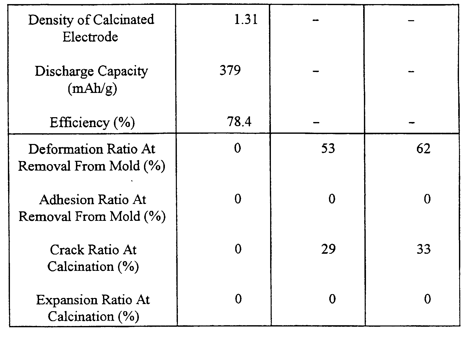
| Results Of Examples 1 to 3 and Comparative Examples 1 to 3 |
| | Comparative Example 1 | Example 1 | Example 2 |
| Oxidizing Temperature (°C) | None | 230 | 250 |
| Oxidizing Duration (Hr) | | 1 | 1 |
| O/C | 0.01 | 0.04 | 0.05 |
| C (%) | 94.0 | 91.1 | 90.5 |
| γ (%) | 5.2 | 2.1 | 1.8 |
| Quantity of Caking Component (%) | 14.8 | 10.4 | 8.6 |
| Density of Calcinated Electrode | 1.36 | 1.31 | 1.31 |
| Discharge Capacity (mAh/g) | 345 | 371 | 377 |
| Efficiency (%) | 70.3 | 79.1 | 78.7 |
| Deformation Ratio At Removal From Mold (%) | 0 | 0 | 0 |
| Adhesion Ratio At Removal From Mold (%) | 23 | 0 | 0 |
| Crack Ratio At Calcination (%) | 0 | 0 | 0 |
| Expansion Ratio At Calcination (%) | 23 | 0 | 0 |
| |
| | Example 3 | Comparative Example 2 | Comparative Example 3 |
| Oxidizing Temperature (°C) | 300 | 350 | 380 |
| Oxidizing Duration (Hr) | 1 | 1 | 1 |
| O/C | 0.06 | 0.09 | 0.11 |
| C (%) | 90.4 | 83.0 | 79.0 |
| γ (%) | 0.5 | 0.2 | 0.2 |
| Quantity of Caking Component (%) | 6.8 | 4.8 | 3.1 |
| Density of Calcinated Electrode | 1.25 | 1.22 | 1.16 |
| Discharge Capacity (mAh/g) | 385 | 382 | 368 |
| Efficiency (%) | 79.8 | 72.1 | 67.2 |
| Deformation Ratio At Removal From Mold (%) | 0 | 29 | 44 |
| Adhesion Ratio At Removal From Mold (%) | 0 | 0 | 0 |
| Crack Ratio At Calcination (%) | 0 | 0 | 17 |
| Expansion Ratio At Calcination (%) | 0 | 0 | 0 |
Powder of the carbonaceous raw material which was the same as that according
to Comparative Example 1 and weighted 10 kg was introduced into a kneader having
a capacity of 15 litters. While powder was being stirred at a speed of 22 rpm in an air
flow, powder was oxidized at 250°C for 10 hours. Obtained powder was molded and
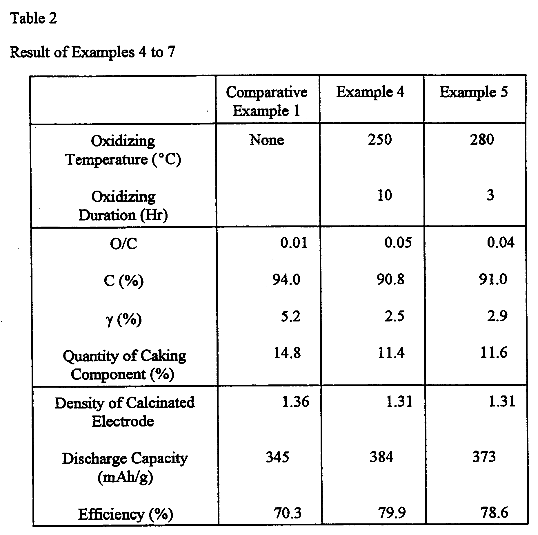
calcinated so as to be evaluated. Results were shown in Table 2.
Example 5
A similar process was performed similarly to Example 4 except for the
oxidizing process performed at 280°C for 3 hours. Results were shown in Table 2.
Example 6
A similar process was performed similarly to Example 4 except for the
oxidizing process performed at 280°C for 7 hours. Results were shown in Table 2.
Example 7
A similar process was performed similarly to Example 4 except for the
oxidizing process performed at 330°C for 3 hours. Results were shown in Table 2.
Powder of the carbonaceous raw material which was the same as that according
to Comparative Example 1 and weighted 10 kg was introduced into a kneader having
a capacity of 15 litters. While powder was being stirred at a speed of 22 rpm in an air
flow, powder was oxidized at 250°C for 6 hours. Obtained powder of the
carbonaceous raw material weighted about 80 g was placed in a 18 × 14 cm
stainless-steel tray to have a height of about 1 cm and a flat surface. Powder was
placed in a small and closed-type electric furnace to raise the temperature to 300°C
at a raising ratio of 300°C/hour in an argon gas flow. Then, powder was heated at the
foregoing temperature for one hour so that a sample was obtained. The quantity of the
γ component, the quantity of the caking component of powder and results of evaluation
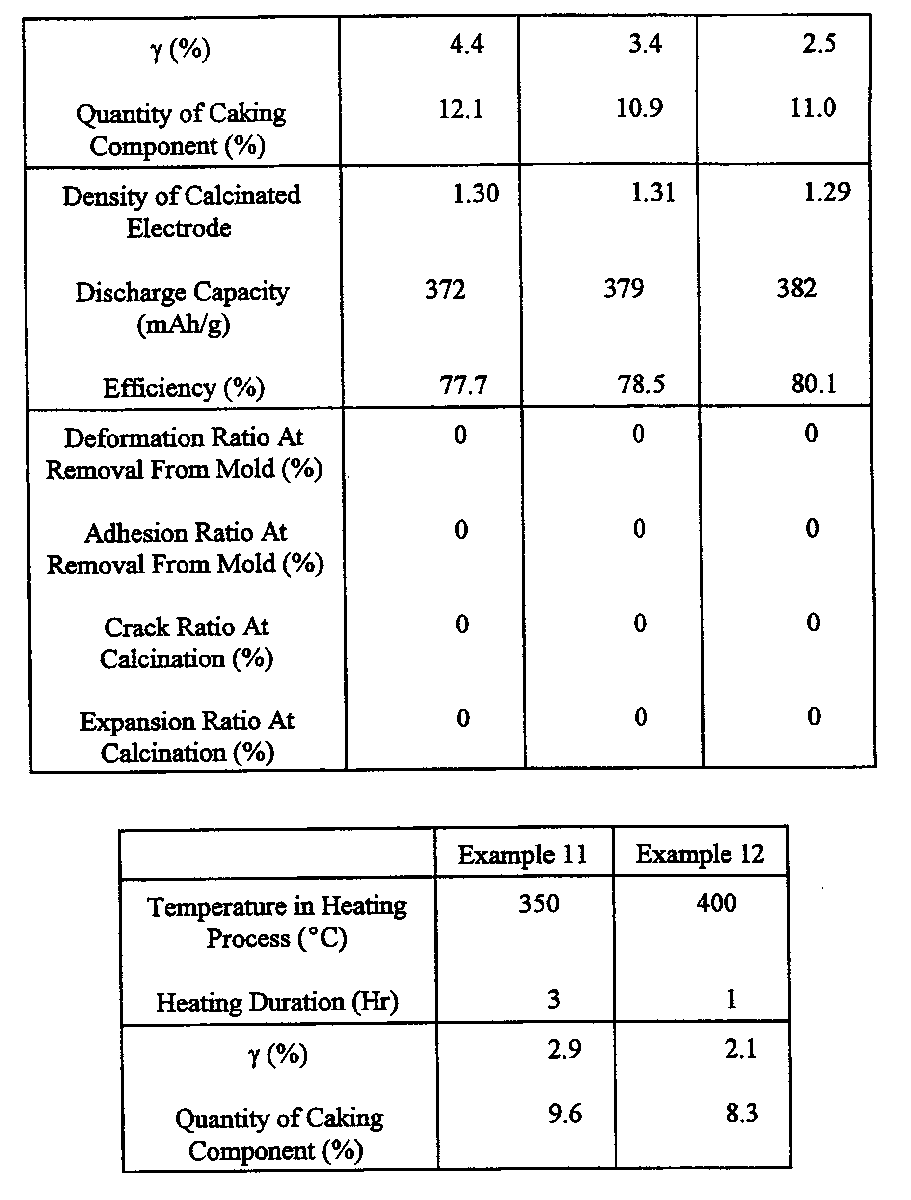
of the molded and calcinated powder were shown in Table 3.
Example 9
A process which was the same as that according to Example 8 was performed
except for the duration of heating in an argon atmosphere which was 3 hours. Results
were shown in Table 3.
Example 10
A process which was the same as that according to Example 8 was performed
except for the heating process performed at 350°C for one hour in an argon
atmosphere. Results were shown in Table 3.
Example 11
A process which was the same as that according to Example 8 was performed
except for the heating process performed at 350°C for one hour in an argon
atmosphere. Results were shown in Table 3.
Example 12
A process which was the same as that according to Example 8 was performed
except for the heating process performed at 350°C for one hour in an argon
atmosphere. Results were shown in Table 3.
A carbonaceous raw material obtained by heat-treating coal tar pitch at about
400°C and having γ resin by 25.4 wt% and O/C of 0.009 (atomic ratio), carbon in a
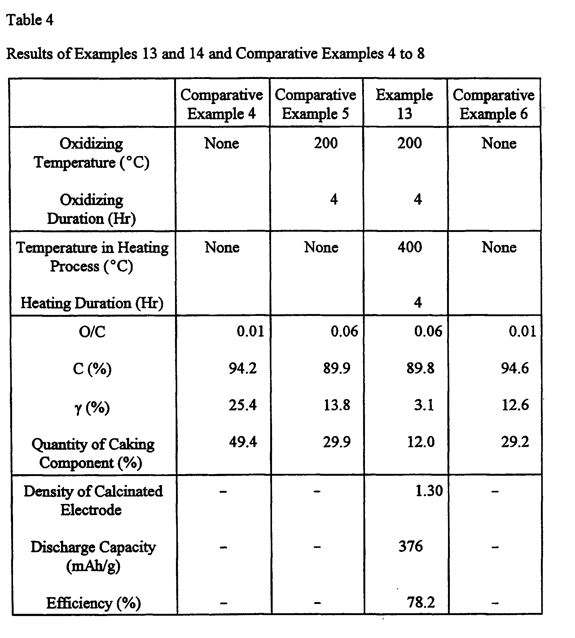
quantity of 94.2 wt% and a caking component in a quantity of 49.4 wt% was formed
into powder having a median diameter of 28 µm. Then, no process was performed,
and then molding and calcination were performed so that a sample was obtained.
Results were shown in Table 4. The measurement of the characteristics of the
electrode manufactured from the obtained sample was impossible because a
predetermined number of complete compacts was not obtained.
Comparative Example 5
Powder of the carbonaceous raw material which was the same as that according
to Comparative Example 4 and which weighted about 200 g was placed in a 28 × 20
cm stainless-steel tray to have a height of about 1 cm and a flat surface. Powder was
placed in a hot oven previously heated to 200°C. Then, powder was subjected to an
oxidizing process for four hour in an air flow. Obtained powder was molded and
calcinated so as to be evaluated. Results were shown in Table 4. The measurement
of the characteristics of the electrode manufactured from the obtained sample was
impossible because a predetermined number of complete compacts was not obtained.
Example 13
Powder of the carbonaceous raw material used in Comparative Example 5,
subjected to an oxidizing process and weighted about 80 g was placed in a 18 × 14 cm
stainless-steel tray to have a height of about 1 cm and a flat surface. The tray was
introduced into a small and close-type electric furnace. The temperature was raised
to 400°C at a raising ratio of 300°C/hour in an argon gas flow. Heat treatment was
performed at the foregoing temperature for 4 hours so that a sample was obtained.
The quantity of the γ component, the quantity of the caking component of powder and
results of evaluation of the molded and calcinated powder were shown in Table 4.
Comparative Example 6
A carbonaceous raw material obtained by heat-treating coal tar pitch at about
450°C and having γ resin by 12.9 wt% and O/C of 0.009 (atomic ratio), carbon in a
quantity of 94.6 wt% and a caking component in a quantity of 12.6 wt% was formed
into powder having a median diameter of 28 µm. Then, no process was performed,
and then molding and calcination were performed so that a sample was obtained.
Results were shown in Table 4. The measurement of the characteristics of the
electrode manufactured from the obtained sample was impossible because a
predetermined number of complete compacts was not obtained.
Example 14
Powder of the carbonaceous raw material which was the same as that according
to Comparative Example 6 and which weighted about 200 g was placed in a 28 × 20
cm stainless-steel tray to have a height of about 1 cm and a flat surface. Powder was
placed in a hot oven previously heated to 250°C. Then, powder was subjected to an
oxidizing process for four hour in an air flow. Powder of the carbonaceous raw
material subjected to the oxidizing process and weighted about 80 g was placed in a
18 cm × 14 cm stainless-steel tray was introduced into a small and close-type electric
furnace. The temperature was raised to 400°C at a raising ratio of 300°C/hour in an
argon gas flow. Heat treatment was performed at the foregoing temperature for 3
hours so that a sample was obtained. The quantity of the γ component, the quantity
of the caking component of powder and results of evaluation of the molded and
calcinated powder were shown in Table 4.
Comparative Example 7
A carbonaceous raw material obtained by heat-treating coal tar pitch at about
500°C and having γ resin by 0.1 wt% and O/C of 0.009 (atomic ratio), carbon in a
quantity of 94.9 wt% and a caking component in a quantity of 2.2 wt% was formed
into powder having a median diameter of 28 µm. Then, no process was performed,
and then molding and calcination were performed so that a sample was obtained.
Results were shown in Table 4. The measurement of the characteristics of the
electrode manufactured from the obtained sample was impossible because a
predetermined number of complete compacts was not obtained.
Comparative Example 8
Powder of the carbonaceous raw material which was the same as that according
to Comparative Example 7 and which weighted about 200 g was placed in a 28 × 20
cm stainless-steel tray to have a height of about 1 cm and a flat surface. Powder was
placed in a hot oven previously heated to 250 °C. Then, powder was subjected to an
oxidizing process for one hour in an air flow. Results of evaluation of obtained
powder subjected to molding and calcination were shown in Table 4. The
measurement of the characteristics of the electrode manufactured from the obtained
sample was impossible because a predetermined number of complete compacts was
not obtained.
A raw material obtained by heat-treating coal tar pitch and having a volatile
component (hereinafter called "VM") in a quantity of 22.1 wt%, γ resin by 25.0 wt%
and an atomic ratio O/C of 0.009 was processed at 280°C for one hour while
mechanical energy was being imparted under presence of air. As a result, a
carbonaceous raw material was obtained which contained VM by 13.6 wt%, γ resin in
a quantity of 7.6 wt%, a solid carbon component by 86.03 wt% and an atomic ratio
O/C of 0.017. The carbonaceous raw material was pulverized so that the median
diameter was made to be 17.3 µm.
Then, the carbonaceous raw material was subjected to an oxidizing process at
280°C in an air atmosphere for 30 minutes. Thus, an oxidation product (the
carbonaceous precursor) was obtained which contained VM by 12.8 wt% and γ resin
by 1.4 wt% and which had an atomic ratio O/C of 0.048.
Then, the oxidation product was formed into a compact having a thickness of
about 1 mm under a pressure of 2 kgf/cm2. Then, the compact was calcinated at
1000°C for 60 minutes in a nitrogen atmosphere so that a carbonaceous material for
a negative electrode which was a sintered body having a bulk density of 1.30 g/cc was
obtained. The particle size of particles which constituted the sintered body was about
15 µm.
Example 16
A raw material obtained by heat-treating coal tar pitch and having a VM in a
quantity of 22. 1 wt%, γ resin by 25.0 wt% and an atomic ratio O/C of 0.009 was
processed at 280°C for one hour while mechanical energy was being imparted under
presence of air. Thus, an oxidation product(the carbonaceous precursor) was obtained
which contained VM by 13.6 wt%, γ resin by 7.6 wt%, a solid carbon component by
86.03 wt% and which had an atomic ratio O/C of 0.017.
Then, the oxidation product was pulverized to make the median diameter to be
17.3 µm. Then, the pulverized material was calcinated at 1000°C for 60 minutes in
a nitrogen atmosphere so that a carbonaceous material for a negative electrode was
prepared.
Example 17
The oxidation product which was the same as that according to Example 16 was
calcinated at 900°C for 60 minutes in a nitrogen atmosphere so that a carbonaceous
material for a negative electrode was prepared.
Example 18
The carbonaceous raw material which was the same as that according to
Example 15 was subjected to an oxidizing process at 210°C for 30 minutes in an air
atmosphere. Thus, an oxidation product was obtained which contained VM by 14.1
wt%, γ resin in a quantity of 4.0 wt% and which had an atomic ratio O/C of 0.022.
Then, the oxidation product was calcinated at 900°C for 60 minutes in a nitrogen
atmosphere so that a carbonaceous material for a negative electrode was prepared.
Example 19
The carbonaceous raw material which was the same as that according to
Example 15 was subjected to an oxidizing process at 260°C for 30 minutes in an air
atmosphere. Thus, an oxidation product was obtained which contained VM by 13.6
wt%, γ resin in a quantity of 0.7 wt% and which had an atomic ratio O/C of 0.039.
Then, the oxidation product was calcinated at 900°C for 60 minutes in a nitrogen
atmosphere so that a carbonaceous material for a negative electrode was prepared.
Example 20
The carbonaceous raw material which was the same as that according to
Example 15 was subjected to an oxidizing process at 350°C for 30 minutes in an air
atmosphere. Thus, an oxidation product was obtained which contained VM by 18.0
wt%, γ resin in a quantity of 0.2 wt% and which had an atomic ratio O/C of 0.09.
Then, the oxidation product was calcinated at 900°C for 60 minutes in a nitrogen
atmosphere so that a carbonaceous material for a negative electrode was prepared.
Example 21
A raw material obtained by heat-treating coal tar pitch and having a VM in a
quantity of 22.1 wt%, γ resin by 25.0 wt% and an atomic ratio O/C of 0.009 was
processed at 260°C for 30 minutes in an air atmosphere. Thus, an oxidation product
was obtained which contained VM by 15.2 wt% and γ resin by 3.0 wt% and which had
an atomic ratio O/C of 0.034.
Then, the oxidation product was formed into a compact having a thickness of
about 1 mm under a pressure of 2 kgf/cm2. Then, the compact was calcinated at
1000°C for 60 minutes in a nitrogen atmosphere so that a carbonaceous material for
a negative electrode which was a sintered body having a bulk density of 1.30 g/cc was
obtained. The particle size of particles which constituted the sintered body was about
15 µm.
Example 22
A raw material obtained by heat-treating coal tar pitch and having a VM in a
quantity of 14.6 wt%, γ resin by 13.0 wt% and an atomic ratio O/C of 0.009 was
processed at 260°C for 30 minutes in an air atmosphere. Thus, an oxidation product
was obtained which contained VM by 17.7 wt% and γ resin by 1.0 wt% and which had
an atomic ratio O/C of 0.078.
Then, the oxidation product was formed into a compact having a thickness of
about 1 mm under a pressure of 2 kgf/cm2. Then, the compact was calcinated at
1000°C for 60 minutes in a nitrogen atmosphere so that a carbonaceous material for
a negative electrode which was a sintered body having a bulk density of 1.30 g/cc was
obtained. The particle size of particles which constituted the sintered body was about
15 µm.
Comparative Example 9
Coal tar pitch was calcinated at 1100°C for 3 hours in an inactive gas
atmosphere so that a carbonaceous material for a negative electrode having a particle
size of 16.2 µm was obtained.
Comparative Example 10
Coal tar pitch was calcinated at 700°C for 3 hours in an inactive gas atmosphere
so that a carbonaceous material for a negative electrode having a particle size of 16.7
µm was obtained.
Comparative Example 11
A carbonaceous raw material obtained by heat-treating coal tar pitch, contained
VM by 5 wt%, γ resin in a quantity of 0.5 wt% or smaller and having an atomic ratio
O/C of 0.007 was pulverized to 45 µm or smaller. Powder of the foregoing
carbonaceous raw material was enclosed in a metal tray at a bulk density of about 0.5
g/cc to have a thickness of about 1 cm. Then, powder was subjected to oxidizing
process at 390°C for 5 hours in an air atmosphere. After the oxidizing process was
completed, an oxidation product having an atomic ratio O/C of 0.35 was obtained from
a range of about 3 mm in the upper portion of the enclosed layer.
Then, the oxidation product was calcinated at 1100°C for 3 hours in a nitrogen
atmosphere so that a carbonaceous material for a negative electrode was obtained.
Comparative Example 12
A carbonaceous raw material obtained by heat-treating coal tar pitch, contained
VM by 5 wt%, γ resin in a quantity of 0.5 wt% or smaller and having an atomic ratio
O/C of 0.007 was pulverized to 45 µm or smaller. Powder of the foregoing
carbonaceous raw material was enclosed in a metal tray at a bulk density of about 0.5
g/cc to have a thickness of about 1 cm. Then, powder was subjected to oxidizing
process at 390°C for 4 hours in an air atmosphere. After the oxidizing process was
completed, an oxidation product having an atomic ratio O/C of 0.35 was obtained from
a range of about 2 mm in the upper portion of the enclosed layer.
Then, the oxidation product was calcinated at 1100°C for 3 hours in a nitrogen
atmosphere so that a carbonaceous material for a negative electrode was obtained.
Comparative Example 13
A carbonaceous raw material obtained by removing light components of
ethylene heavy end, which was petroleum, containing VM by 28.7 wt%, γ resin by
98.2 wt% and having an atomic ratio H/C of 0.83 was pulverized to 45 µm or smaller.
Powder of the foregoing carbonaceous raw material was placed on a metal tray to have
a thickness of about several millimeters, and then powder was subjected to an
oxidizing process at 230°C for 3 hours in an air atmosphere. Thus, an oxidation
product having an atomic ratio O/C of 0.131 was obtained.
Then, the oxidation product was calcinated at 1100°C for 3 hours in a nitrogen
atmosphere so that a carbonaceous material for a negative electrode was obtained.
Comparative Example 14
A process similar to that according to Comparative Example 13 was performed
except for the oxidizing temperature which was 180°C and an oxidation product
having an atomic ratio O/C of 0.049. Thus, a carbonaceous material for a negative
electrode was obtained.
Comparative Example 15
A carbonaceous raw material obtained by removing light components of
ethylene heavy end, which was a petroleum pitch derived from an ethylene bottom,
containing VM by 29.8 wt%, γ resin by 37.1 wt% and having an atomic ratio H/C of
0.67 was pulverized to 45 µm of smaller. Powder of the foregoing carbonaceous raw
material was placed on a metal tray to have a thickness of about several millimeters,
and then powder was subjected to an oxidizing process at 310°C for 3 hours in an air
atmosphere. Thus, an oxidation product having an atomic ratio O/C of 0.254 was
obtained.
Then, the oxidation product was calcinated at 1100°C for 3 hours in a nitrogen
atmosphere so that a carbonaceous material for a negative electrode was obtained.
Conditions under which the oxidizing processes, the quantities of γ resin in the
carbonaceous raw materials and contents of oxygen (the atomic ratios O/C) in the
oxidation products of the examples and comparative examples are shown in Table 5.
| | Oxidizing Condition | Quantity of γ-Resin in Carbonaceous Raw Material (wt%) | O/C of Oxidation Product |
| | Temperature [°C] | Time [Hr] |
| Example 15 | 280 | 0.5 | 7.6 | 0.048 |
| Example 16 | 280 | 1 | 25 | 0.017 |
| Example 17 | 280 | 1 | 25 | 0.017 |
| Example 18 | 210 | 0.5 | 7.6 | 0.022 |
| Example 19 | 260 | 0.5 | 7.6 | 0.039 |
| Example 20 | 350 | 0.5 | 7.6 | 0.09 |
| Example 21 | 260 | 0.5 | 25 | 0.034 |
| Example 22 | 260 | 0.5 | 13 | 0.078 |
| Comparative Example 9 | None | 0.5< | ND |
| Comparative Example 10 | None | 0.5< | MD |
| Comparative Example 11 | 390 | 5 | 0.5< | 0.35 |
| Comparative Example 12 | 390 | 4 | 0.5< | 0.35 |
| Comparative Example 13 | 230 | 3 | 98.2 | 0.131 |
| Comparative Example 14 | 180 | 3 | 98.2 | 0.049 |
| Comparative Example 15 | 310 | 3 | 37.1 | 0.254 |
Volatile component (VM) was obtained in accordance with JIS-M8812.
Evaluation of Characteristics
Table 6 shows beating temperatures, intervals d
002 between (002) planes, the
thicknesses Lc of the crystalline, true densities, atomic ratios H/C, area ratios S0/S1
and average particle sizes of component particles of the carbonaceous materials
obtained in the examples and comparative examples. FIG. 2 shows a scattered X-ray
curve of the carbonaceous material obtained in Example 15 by a transmission method.
The true density was measured by a n-butanol substitution method using a
true-specific-gravity meter(manufactured by Seishin). The carbonaceous raw material
was pulverized to 45 µm or smaller, and then dried at 105°C for one hour. Then, the
raw material was cooled to room temperature in a nitrogen gas flow so as to be
measured.
The atomic ratio H/C, that is, the content of hydrogen with respect to carbon
was calculated by using their atomic weights obtained from weight content ratios of
carbon and hydrogen. The contents of carbon and hydrogen were measured by a
full-automatic element analyzing apparatus (CHN meter 240C manufactured by Parkin
Elmer).
The particle size of component particles was measured by a laser diffraction and
scattering method using a particle size distribution measuring apparatus ("LA-500"
manufactured by Horiba) in 0.1 wt% water solution of sodium oleate. The average
particle size was obtained as the particle size and the median diameter which was the
particle size with which the estimation in terms of the volume was 50 %.
The intervals d
022 between (002) planes and the thickness Lc of the crystalline
were obtained by X-ray diffraction conforming to a method suggested by committee
117 of Japan Society of for the Promotion of Science. The following apparatuses and
measuring conditions were employed.
(graphite was used as monochrome meter) X-Ray Output: 40 kV, 30 mA Measuring Layout: reflecting method Measuring Method: step scan method was employed at 0.02 degree/step
estimated time of 1 second
The area ratio S0/S1 is an area ratio of S0 with respect to S1. An assumption
is made that an area enclosed by a base line which is a common tangent line
connecting minimal values (which appear adjacent to 2 = 15° and 30°) on the two
sides of a (002) diffraction line in a scattered X-ray curve obtained by X-ray
diffraction measurement and the (002) diffraction line is S1. Another assumption is
made that an area enclosed by a scattered X-ray curve having a
diffraction angle 2
of 4° or more and positioned in lower angle portions as compared with the (002)
diffraction line and the base line is S0. In the foregoing case, an area ratio S0/S1 is 0.4
to 2.0. The following apparatuses and measuring conditions were employed:
The sintered bodies (carbonaceous materials for a negative electrode) according
to the examples and comparative examples were slightly pulverized to make the radian
diameter to be 15 µm. The obtained material was employed as the active material for
the negative electrode. The particle size of powder employed to evaluate the battery
was substantially the same as basic particles which constituted the sintered body.
Thus, the evaluation of the battery showed the characteristics of the basic particles of
the sintered body.
Referring to FIG.3, a method of manufacturing a battery will now be described.
Initially, positive-electrode pellet 1 was prepared as follows.
As an active material in a positive electrode, 0.5 mole of lithium carbonate and
1 mole of cobalt carbonate were mixed, after which the mixture was calcinated in air
at 900°C for 5 hours so that LiCoO2 was obtained. LiCoO2 was pulverized into
powder having an average particle size of 10 µm. Then, 91 parts by weight of LiCoO2,
6 parts by weight of graphite serving as a conductive material and 3 parts by weight
of polyvinylidene fluoride serving as a binder were mixed, and then N-methyl
pyrrolidine was added as a dispersant. Thus, paste was prepared. Paste was dried, and
then molded to have a diameter of 15.5 mm. Thus, the positive-electrode pellet 1 was
prepared.
Then, negative-electrode pellet 2 was prepared as follows.
Ninety parts by weight of carbonaceous material for a negative electrode
according to each of examples and comparative examples were employed as the active
material for a negative electrode. Then, 10 parts by weight of polyvinylidene fluoride
were added so as to be mixed. Then, N-methyl pyrrolidine was added as a dispersant
so that paste was prepared. Then, paste was dried and molded to have a diameter of
16 mm so that the negative-electrode pellet 2 was prepared.
Then, the positive-electrode pellet 1 was accommodated in a positive-electrode
can 3 made of aluminum, while the negative-electrode pellet 2 was accommodated in
a negative-electrode cup 4 made of stainless steel (SUS304). Then, the
positive-electrode pellet 1 and the negative-electrode pellet 2 were laminated through
propropylene separator 5. Then, a gasket 6 was placed so as to be crimped so that a
corn-type secondary battery having a diameter of 20 mm and a thickness of 2.5 mm
was manufactured.
Then, as shown in FIG. 4, an electrolyte 11 was injected into a cell 10 for
measuring charge/discharge capacity, the electrolyte 11 being prepared by dissolving
LiPF6 by 1 mol/l in mixed solvent of ethylene carbonate and diethyl carbonate. An
opening which reached the side surface of the above-mentioned coin-type secondary
battery was formed so as to be immersed in the electrolyte 11 in the cell for measuring
charge/discharge capacity. Then, a positive electrode 12 was connected to the
positive-electrode can 3, and then a negative electrode 13 was connected to a
negative-electrode cup 4. Moreover, lithium metal 15 serving as a reference electrode
14 was employed so that 3-electrode cell was manufactured.
A 0.25 mA constant current was used at room temperature to perform charging
until the potential of the negative electrode 13 reached 0 V. A 0.25 mA constant
current was used to perform discharge until the potential of the negative electrode 13
reached 1.5 V. Then, charge/discharge capacity was measured. When the
predetermined potentials were realized, both of the charging and discharging
operations were completed. Obtained characteristics as the battery were collectively
shown in Table 6.
The carbonaceous materials according to the examples were obtained by
oxidizing carbonaceous raw materials having γ resin in a quantity of 0.5 wt% to 30
wt% so that the oxidation products having the element ratios O/C of 0.0 1 to 0.2 was
obtained. Then, the oxidation products were calcinated. As shown in Table 6, the
foregoing carbonaceous materials had optimized parameters including the intervals d002
between (002) planes, the thicknesses Lc of the crystalline, the true densities, the
atomic ratios H/C, the area ratios S0/S1 and the average particle sizes of component
particles. Moreover, the batteries containing the carbonaceous materials having the
optimized parameters as the negative electrodes had large charge/discharge capacities.
On the other hand, the carbonaceous materials subjected no oxidizing process
and carbonaceous materials obtained by using the carbonaceous raw materials
containing resin in too small quantities or in too large quantities have the parameter
which were not optimized. The batteries containing the foregoing carbonaceous
materials suffers from small charge/discharge capacities or excessive capacity losses.