EP0935690B1 - Procede pour realiser une liaison etanche entre le corps de chauffe d'une semelle de fer a repasser a vapeur et une plaque et semelle de fer a repasser ainsi obtenue - Google Patents
Procede pour realiser une liaison etanche entre le corps de chauffe d'une semelle de fer a repasser a vapeur et une plaque et semelle de fer a repasser ainsi obtenue Download PDFInfo
- Publication number
- EP0935690B1 EP0935690B1 EP98946504A EP98946504A EP0935690B1 EP 0935690 B1 EP0935690 B1 EP 0935690B1 EP 98946504 A EP98946504 A EP 98946504A EP 98946504 A EP98946504 A EP 98946504A EP 0935690 B1 EP0935690 B1 EP 0935690B1
- Authority
- EP
- European Patent Office
- Prior art keywords
- plate
- groove
- heater body
- resin
- soleplate
- Prior art date
- Legal status (The legal status is an assumption and is not a legal conclusion. Google has not performed a legal analysis and makes no representation as to the accuracy of the status listed.)
- Expired - Lifetime
Links
Images

Classifications
-
- D—TEXTILES; PAPER
- D06—TREATMENT OF TEXTILES OR THE LIKE; LAUNDERING; FLEXIBLE MATERIALS NOT OTHERWISE PROVIDED FOR
- D06F—LAUNDERING, DRYING, IRONING, PRESSING OR FOLDING TEXTILE ARTICLES
- D06F75/00—Hand irons
- D06F75/38—Sole plates
Definitions
- the present invention relates to a method for make a tight connection between the heating body a soleplate of steam iron and a plate often called a cap forming the ironing surface iron.
- the invention also relates to the iron soleplate ironing carried out by the aforementioned process.
- the heating element of the sole is generally made of aluminum by molding, the tubular resistance heating being embedded in the sole body.
- the plate or cap of the sole is generally made of an aluminum sheet whose surface of ironing is advantageously coated with a layer facilitating the sliding of the iron, such as a layer of enamel.
- This plate or cap has holes for passage of steam which communicate with the chamber of vaporization of the iron carried out above the heating body.
- This cap must be fixed in a watertight manner to the heater.
- This fixing can be achieved by means of a resin layer resistant to heating temperature the sole and applied between the parts in contact with the heating element and cover, for example by screen printing (see for example EP-A-0267838 and GB-A-2225345).
- the object of the present invention is to remedy the above drawback, by proposing a method allowing a tight connection between the body of heating and the plate which is of simple implementation and economical and which guarantees a tight connection particularly reliable, especially when the area of contact surfaces between heating elements and headdress is weak.
- the invention thus relates to a method for carrying out a tight connection with a resin between the heating body of a sole steam iron and a plate making up the ironing surface of said iron, the plate comprising steam outlet holes.
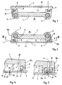
- this process is characterized in what the face of the heater intended to be covered by said plate has a groove extending at least around the entire periphery of said heating body, in keeping said heating body flat, the face with the groove facing upwards, a resin flows into said groove, we apply said plate on said face of the heating body, we return the assembly so that the plate is directed downwards, to pour the resin in the part of the throat adjacent to the plate.
- the resin used can be a silicone resin which withstands heating temperature (about 250 ° C) the soleplate of the iron.
- the resin poured into the groove is applied to the surface of the plate which covers the throat by forming a thick bead predetermined.
- the returned assembly is heated with way to speed up or get the hardening of the resin.
- the invention also relates to the iron soleplate ironing carried out according to the process according to the invention.
- each of the branches of said groove adjacent to the respective longitudinal edges of the a heating body is crossed by a series of conduits whose end adjacent to the bottom of said branch communicates by a channel with a vaporization chamber and the other end of which opens into a hole in the plate applied to the heating body.
- the resin poured into said groove surrounds the end adjacent to the plate of each duct and is in contact with the surface of the plate which covers the throat.
- the holes of steam passage practiced in the plate are extended towards the heating body by parts tubular formed in said plate, the latter being engaged and crimped in the conduits located in the groove of the heating body.
- the heating body 1 has a resistance heating tube 5 which surrounds one (or more) vaporization chamber (s) 26 located on the side of the body heater 1 opposite the cover 2.
- This plate 2 has (see fig. 3 to 7) holes 4 steam outlet formed in the chamber spray 26.
- the face 6 of the body of heater 1 intended to be covered by the plate 2 has a groove 7 extending at least over the whole around the heating body 1.
- the heating body 1 flat, the face 6 having the groove 7 being directed upwards, as shown in Figure 1.
- a third step we then heats the assembly, for example in an oven, to harden the resin when the chosen resin does not does not polymerize at room temperature, or polymerizes too much slowly.
- the resin 8 used is a resin silicone.
- a resin is temperature resistant maximum service of an iron soleplate.
- each of the branches 15a, 15b of the groove 7 adjacent to the respective longitudinal edges 25a, 25b of the heating body 1 is crossed by a series of conduits 10 of which the end adjacent to the bottom 9 of said branch 15a, 15b communicates via a channel 11 with the vaporization chamber 26 and the other end of which opens into a hole 4 practiced in the plate 2 applied to the heating body 1, as shown in Figure 5.
- Figure 5 also shows that the resin 8 poured into the groove 7 surrounds the end 10a adjacent to the plate 2 of each conduit 10 and is in contact with the surface 2a of the plate 2 which covers the throat 7.
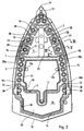
- the groove 7 has substantially the shape of a Inverted V whose point 13 is adjacent to point 14 of the sole and the end 16a, 16b of the two branches 15a, 15b opposite the tip 13, communicates with a groove 17 which connects these two branches 15a, 15b.
- a groove 22 connects the two branches 15a, 15b of the groove 7 between the point 13 and throat 17.
- the heating body 1 has, between the grooves 15a, 15b and the groove 22, a chamber 3 constituting a first steam distribution chamber 3 which is closed by plate 2 and which communicates with the outside by holes 27 made in the thickness of the plate 2.
- the first steam distribution chamber 3 communicates with the vaporization chamber 26 by channels 28 each formed between two adjacent channels 11 and each ending in the first distribution chamber 3 by a cell 29 formed by a portion 30 in the form of U open to chamber 3 of the inner wall 31 of the corresponding branch 15a, 15b of the groove 7.
- the ends 16a, 16b of the two branches 15a, 15b of the groove 7 in inverted V are interconnected by a second groove 18 which extends near the rear edge 19 of the heating body 1.
- the second distribution chamber 20 of steam communicates with the vaporization chamber 26 by channels 38 each terminating in said second chamber by a cell 39 formed in a portion of a wall 37 delimiting the grooves 17,18 and the second chamber 20 distribution.
- This resin 8 partially fills the groove 7 in inverted V shape, grooves 17 and 18, as well as the throat 22 which connects the two branches 15a, 15b of the groove 7.
- a vent 32 brings communication inside the throat 7 with the outside to facilitate this operation.
- the resin joint thus produced along the grooves 7, 15a, 15b, 17, 18 and 22 thus frees the whole part central of the inner face of the heater 1 and the central part of the cap 2, and thus makes it possible to produce steam distribution chambers such as rooms 3 and 20 described.
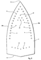
- Distribution chambers 3 and 20 can be connected to one (or more) vaporization chamber (s) from that supplying the channels 10 and the holes 4, which allows fine adjustment of the passage of steam to through cap 2 towards the ironing cloth, taking care on the cap 2 several steam inlet zones formed respectively by holes 4, 21 and 27.
- the steam path is shown schematically by the arrows 33 in Figures 4 and 5.
- the central zone of the cap 2 formed between these three zones thus constitute a zone for heating the laundry dried up.
- the invention finds its application in the field irons.
Landscapes
- Engineering & Computer Science (AREA)
- Textile Engineering (AREA)
- Irons (AREA)
- General Induction Heating (AREA)
- Cookers (AREA)
- Mounting, Exchange, And Manufacturing Of Dies (AREA)
Description
- la figure 1 est une vue schématique en coupe transversale d'un corps de chauffe d'une semelle de fer à repasser à vapeur, après coulée d'une résine dans la gorge du corps de chauffe ;
- la figure 2 est une vue analogue à la figure 1, après application de la plaque et retournement de l'ensemble ;
- la figure 3 est une vue en coupe selon III-III à la figure 2 ;
- la figure 4 est une vue partielle en coupe selon IV-IV à la figure 3 ;
- la figure 5 est une vue partielle en coupe selon V-V à la figure 3 ;
- la figure 6 est une vue en plan d'un mode de réalisation de la face de repassage de la plaque destinée à recouvrir le corps de chauffe de la figure 3 ;
- la figure 7 est une vue semblable à la figure 6 d'un autre mode de réalisation de l'invention.
Claims (13)
- Procédé pour réaliser une liaison étanche avec une resine (8) entre le corps de chauffe (1) d'une semelle de fer à repasser à vapeur et une plaque (2) constituant la surface de repassage dudit fer, cette plaque (2) comportant des trous (4) de sortie de la vapeur, caractérisé en ce que la face (6) du corps de chauffe (1) destinée à être recouverte par ladite plaque (2) comporte une gorge (7) s'étendant au moins sur tout le pourtour dudit corps de chauffe (1), en ce que l'on maintient ledit corps de chauffe (1) à plat, la face (6) comportant la gorge (7) étant dirigée vers le haut, on coule ladite résine (8) dans ladite gorge (7), on applique ladite plaque (2) sur ladite face (6) du corps de chauffe (1), on retourne l'ensemble de façon que la plaque (2) soit dirigée vers le bas, pour faire couler la résine (8) dans la partie de la gorge (7) adjacente à la plaque (2).
- Procédé conforme à la revendication 1, caractérisé en ce que l'on chauffe ensuite l'ensemble, pour faire durcir la résine (8).
- Procédé conforme à la revendication 1 ou à la revendication 2, caractérisé en ce que la résine utilisée est une résine silicone.
- Semelle de fer à repasser à vapeur comprenant un corps de chauffe (1) et une plaque (2) constituant la surface de repassage dudit fer, une liaison étanche avec une résine (8) étant réalisée entre le corps de chauffe (1) et la plaque (2), caractérisée en ce que la face (6) du corps de chauffe (1) destinée à être recouverte par ladite plaque (2) comporte une gorge (7) s'étendant au moins sur tout le pourtour dudit corps de chauffe (1), ladite résine (8) étant coulée dans ladite gorge (7) pendant le procédé de fabrication de la semelle, ladite liaison étanche étant réalisée selon le procédé conforme à l'une des revendications 1 à 3.
- Semelle conforme à la revendication 4, caractérisée en ce que chacune des branches (15a, 15b) de ladite gorge (7) adjacentes aux bords longitudinaux respectifs (25a, 25b) du corps de chauffe (1) est traversée par série de conduits (10) dont l'extrémité adjacente au fond (9) de ladite branche (15a, 15b) communique par un canal (11) avec une chambre de vaporisation (26) et dont l'autre extrémité (10a) débouche dans un trou (4) pratiqué dans la plaque (2) appliquée sur le corps de chauffe (1).
- Semelle conforme à la revendication 5, caractérisée en ce que la résine (8) coulée dans ladite gorge (7) entoure l'extrémité (10a) adjacente à la plaque (2) de chaque conduit (10) et est en contact avec la surface (2a) de la plaque (2) qui recouvre la gorge (7).
- Semelle conforme à l'une des revendications 5 ou 6, caractérisée en ce que les trous (4) de passage de la vapeur pratiqués dans la plaque (2) sont prolongés vers le corps de chauffe (1) par des parties tubulaires (12) formées dans ladite plaque (2), ces dernières étant engagées et serties dans les conduits (10) situés dans la gorge (7) du corps de chauffe (1).
- Semelle conforme à l'une des revendications 5 à 7, caractérisée en ce que ladite gorge (7) a sensiblement la forme d'un V inversé dont la pointe (13) est adjacente à la pointe de la semelle et dont l'extrémité (16a, 16b) des deux branches (15a, 15b) opposée à la pointe (13) communique avec une gorge (17) qui relie ces deux branches (15a, 15b).
- Semelle conforme à la revendication 8, caractérisée en ce qu'une gorge (22) relie les deux branches (15a, 15b) de la gorge (7) entre la pointe (13) de la gorge (17).
- Semelle conforme à la revendication 9, caractérisée en ce que le corps de chauffe (1) présente, entre les gorges (15a, 15b) et la gorge (22), une chambre (3) constituant une première chambre (3) de répartition de vapeur qui est fermée par la plaque (2) et qui communique avec l'extérieur par des trous (27) ménagés dans l'épaisseur de la plaque (2).
- Semelle conforme à la revendication 10, caractérisée en ce que la première chambre (3) de répartition de vapeur communique avec la chambre de vaporisation (26) par des canaux (28) ménagés chacun entre deux canaux (11) adjacents et aboutissant chacun dans la première chambre de répartition (3) par une alvéole (29) ménagée par une portion (30), en forme de U ouvert vers la chambre (3), de la paroi intérieure (31) de la branche correspondante (15a, 15b) de la gorge (7).
- Semelle conforme à l'une des revendications 8 à 11, caractérisée en ce que les extrémités (16a, 16b) des deux branches (15a, 15b) de la gorge (7) en V inversé sont reliées entre elles par une seconde gorge (18) qui s'étend près du bord arrière (19) du corps de chauffe (1)
- Semelle conforme à la revendication 12, caractérisée en ce que les deux gorges (17, 18) reliant entre elles les extrémités (16a, 16b) des deux branches (15a, 15b) de la gorge (7) en V inversé, entourent une seconde chambre (20) de répartition de vapeur qui débouche à l'extérieur par des trous (21) pratiqués dans la partie arrière de la plaque (2).
Applications Claiming Priority (3)
| Application Number | Priority Date | Filing Date | Title |
|---|---|---|---|
| FR9711098 | 1997-09-02 | ||
| FR9711098A FR2767845B1 (fr) | 1997-09-02 | 1997-09-02 | Procede pour realiser une liaison etanche entre le corps de chauffe d'une semelle de fer a repasser a vapeur et une plaque et semelle de fer a repasser ainsi obtenue |
| PCT/FR1998/001875 WO1999011855A1 (fr) | 1997-09-02 | 1998-09-01 | Procede pour realiser une liaison etanche entre le corps de chauffe d'une semelle de fer a repasser a vapeur et une plaque et semelle de fer a repasser ainsi obtenue |
Publications (2)
| Publication Number | Publication Date |
|---|---|
| EP0935690A1 EP0935690A1 (fr) | 1999-08-18 |
| EP0935690B1 true EP0935690B1 (fr) | 2002-07-31 |
Family
ID=9510827
Family Applications (1)
| Application Number | Title | Priority Date | Filing Date |
|---|---|---|---|
| EP98946504A Expired - Lifetime EP0935690B1 (fr) | 1997-09-02 | 1998-09-01 | Procede pour realiser une liaison etanche entre le corps de chauffe d'une semelle de fer a repasser a vapeur et une plaque et semelle de fer a repasser ainsi obtenue |
Country Status (9)
| Country | Link |
|---|---|
| US (1) | US6125562A (fr) |
| EP (1) | EP0935690B1 (fr) |
| JP (1) | JP2001505117A (fr) |
| AT (1) | ATE221590T1 (fr) |
| AU (1) | AU9353098A (fr) |
| CA (1) | CA2270584A1 (fr) |
| DE (1) | DE69806892D1 (fr) |
| FR (1) | FR2767845B1 (fr) |
| WO (1) | WO1999011855A1 (fr) |
Families Citing this family (7)
| Publication number | Priority date | Publication date | Assignee | Title |
|---|---|---|---|---|
| CN2530971Y (zh) * | 2001-12-31 | 2003-01-15 | 广东德豪润达电气股份有限公司 | 一种低温蒸汽电熨斗 |
| WO2003085189A1 (fr) * | 2002-04-10 | 2003-10-16 | Termozeta S.P.A. | Fer et semelle pour un fer a repasser |
| JP2009028385A (ja) * | 2007-07-30 | 2009-02-12 | Hitachi Living Supply:Kk | アイロン |
| JP5974274B2 (ja) * | 2011-03-24 | 2016-08-23 | パナソニックIpマネジメント株式会社 | アイロン |
| CN105229219B (zh) * | 2013-07-25 | 2018-04-24 | 皇家飞利浦有限公司 | 用于产生蒸汽的装置 |
| WO2016030175A1 (fr) * | 2014-08-26 | 2016-03-03 | Koninklijke Philips N.V. | Fer à vapeur |
| CN111809377A (zh) * | 2020-07-31 | 2020-10-23 | 宁波凯波智能熨烫电器制造有限公司 | 熨烫面板及熨烫器 |
Family Cites Families (8)
| Publication number | Priority date | Publication date | Assignee | Title |
|---|---|---|---|---|
| FR2606043B1 (fr) * | 1986-10-31 | 1988-12-30 | Seb Sa | Fer a repasser a vapeur |
| GB2225345A (en) * | 1988-10-21 | 1990-05-30 | Russell Hobbs Tower Limited | Electrically heated irons with composite sole plate |
| US5146700A (en) * | 1991-10-31 | 1992-09-15 | Coors Technical Ceramics Company | Steam iron with bonded ceramic and aluminum components |
| US5273606A (en) * | 1991-12-16 | 1993-12-28 | The Budd Company | Bonding technique for a multi-panel device |
| US5907916A (en) * | 1995-03-09 | 1999-06-01 | Braun Aktiengesellschaft | Smoothing iron with adhered soleplate |
| DE19508446A1 (de) * | 1995-03-09 | 1996-09-12 | Braun Ag | Bügeleisen |
| JPH1050769A (ja) * | 1996-07-30 | 1998-02-20 | Toshiba Corp | 半導体パッケージの製造装置および製造方法 |
| US5937552A (en) * | 1997-01-10 | 1999-08-17 | Hp Intellectual Corp. | Iron soleplate with a soleplate bottom cover |
-
1997
- 1997-09-02 FR FR9711098A patent/FR2767845B1/fr not_active Expired - Fee Related
-
1998
- 1998-09-01 JP JP51638699A patent/JP2001505117A/ja active Pending
- 1998-09-01 DE DE69806892T patent/DE69806892D1/de not_active Expired - Lifetime
- 1998-09-01 AU AU93530/98A patent/AU9353098A/en not_active Abandoned
- 1998-09-01 AT AT98946504T patent/ATE221590T1/de active
- 1998-09-01 US US09/297,556 patent/US6125562A/en not_active Expired - Fee Related
- 1998-09-01 CA CA002270584A patent/CA2270584A1/fr not_active Abandoned
- 1998-09-01 WO PCT/FR1998/001875 patent/WO1999011855A1/fr not_active Ceased
- 1998-09-01 EP EP98946504A patent/EP0935690B1/fr not_active Expired - Lifetime
Also Published As
| Publication number | Publication date |
|---|---|
| FR2767845A1 (fr) | 1999-03-05 |
| JP2001505117A (ja) | 2001-04-17 |
| ATE221590T1 (de) | 2002-08-15 |
| WO1999011855A1 (fr) | 1999-03-11 |
| CA2270584A1 (fr) | 1999-03-11 |
| AU9353098A (en) | 1999-03-22 |
| EP0935690A1 (fr) | 1999-08-18 |
| US6125562A (en) | 2000-10-03 |
| DE69806892D1 (de) | 2002-09-05 |
| FR2767845B1 (fr) | 1999-10-15 |
Similar Documents
| Publication | Publication Date | Title |
|---|---|---|
| EP3146864B1 (fr) | Tete de distribution et d'application | |
| EP2503052A1 (fr) | Fer à repasser à vapeur comportant une plaque de repassage comprenant au moins un premier groupe et un deuxième groupe de trous de sortie de vapeur | |
| FR2640857A1 (en) | Hairdryer with an air exit flow of modifiable form | |
| FR2480635A1 (fr) | Buse d'injection pour machine a mouler sous pression | |
| CA2270584A1 (fr) | Procede pour realiser une liaison etanche entre le corps de chauffe d'une semelle de fer a repasser a vapeur et une plaque et semelle de fer a repasser ainsi obtenue | |
| FR2693894A1 (fr) | Procédé pour modifier les caractéristiques d'une surface de métal. | |
| WO2003006859A1 (fr) | Vanne de commande a etancheite amelioree et son procede de fabrication | |
| FR3043376A1 (fr) | Volant et procede de fabrication d'un tel volant. | |
| FR2552706A1 (fr) | Element chauffant electrique avec canal interne pour l'ecoulement de matiere plastique en fusion | |
| FR2587468A1 (fr) | Procede pour la liaison entre les tubes et les plaques collectrices d'un echangeur de chaleur et echangeur obtenu par ce procede | |
| FR2815691A1 (fr) | Bille de clapet | |
| BE735915A (fr) | Tube muni d'un corps ä partir d'une feuille ou d'un tuyau et d'une tète, ainsi que procédé et dispositif pour la réalisation dudit tube | |
| FR2741364A1 (fr) | Fer a repasser electrique a vapeur | |
| EP0909629B1 (fr) | Installation pour la fabrication par dépression de corps tubulaires en matière synthétique | |
| EP1945858B1 (fr) | Moule pour la soudure aluminothermique de rails de chemin de fer | |
| FR2648166A1 (fr) | Semelle de fer a repasser a plaque rapportee et fer a repasser comportant une telle semelle | |
| EP1069845A1 (fr) | Procede et dispositif pour la realisation d'un maquillage | |
| EP0600812A1 (fr) | Manche de fouet culinaire et son procédé de fabrication | |
| FR2528724A1 (fr) | Douchette a deux positions de jet avec obturateur reversible | |
| EP0323348A1 (fr) | Procédé pour réaliser une plaque chauffante et article chauffant s'y rapportant | |
| FR2674914A1 (fr) | Procede de fabrication de produits par assemblage colle de pieces. | |
| EP0713937B1 (fr) | Fer à repasser comportant une semelle améliorée | |
| CA1117842A (fr) | Appareillage pour le chauffage de bigoudis | |
| FR2481983A1 (fr) | Couteau pour pose de revetements de sol en matiere plastique | |
| FR2723432A1 (fr) | Panneau decoratif chauffant et moule permettant sa fabrication. |
Legal Events
| Date | Code | Title | Description |
|---|---|---|---|
| PUAI | Public reference made under article 153(3) epc to a published international application that has entered the european phase |
Free format text: ORIGINAL CODE: 0009012 |
|
| 17P | Request for examination filed |
Effective date: 19990412 |
|
| AK | Designated contracting states |
Kind code of ref document: A1 Designated state(s): AT BE DE ES FR GB IT NL |
|
| GRAG | Despatch of communication of intention to grant |
Free format text: ORIGINAL CODE: EPIDOS AGRA |
|
| 17Q | First examination report despatched |
Effective date: 20011106 |
|
| GRAG | Despatch of communication of intention to grant |
Free format text: ORIGINAL CODE: EPIDOS AGRA |
|
| GRAH | Despatch of communication of intention to grant a patent |
Free format text: ORIGINAL CODE: EPIDOS IGRA |
|
| GRAH | Despatch of communication of intention to grant a patent |
Free format text: ORIGINAL CODE: EPIDOS IGRA |
|
| GRAA | (expected) grant |
Free format text: ORIGINAL CODE: 0009210 |
|
| AK | Designated contracting states |
Kind code of ref document: B1 Designated state(s): AT BE DE ES FR GB IT NL |
|
| PG25 | Lapsed in a contracting state [announced via postgrant information from national office to epo] |
Ref country code: NL Free format text: LAPSE BECAUSE OF FAILURE TO SUBMIT A TRANSLATION OF THE DESCRIPTION OR TO PAY THE FEE WITHIN THE PRESCRIBED TIME-LIMIT Effective date: 20020731 Ref country code: IT Free format text: LAPSE BECAUSE OF FAILURE TO SUBMIT A TRANSLATION OF THE DESCRIPTION OR TO PAY THE FEE WITHIN THE PRESCRIBED TIME-LIMIT;WARNING: LAPSES OF ITALIAN PATENTS WITH EFFECTIVE DATE BEFORE 2007 MAY HAVE OCCURRED AT ANY TIME BEFORE 2007. THE CORRECT EFFECTIVE DATE MAY BE DIFFERENT FROM THE ONE RECORDED. Effective date: 20020731 Ref country code: GB Free format text: LAPSE BECAUSE OF FAILURE TO SUBMIT A TRANSLATION OF THE DESCRIPTION OR TO PAY THE FEE WITHIN THE PRESCRIBED TIME-LIMIT Effective date: 20020731 Ref country code: AT Free format text: LAPSE BECAUSE OF FAILURE TO SUBMIT A TRANSLATION OF THE DESCRIPTION OR TO PAY THE FEE WITHIN THE PRESCRIBED TIME-LIMIT Effective date: 20020731 |
|
| REF | Corresponds to: |
Ref document number: 221590 Country of ref document: AT Date of ref document: 20020815 Kind code of ref document: T |
|
| REG | Reference to a national code |
Ref country code: GB Ref legal event code: FG4D Free format text: NOT ENGLISH |
|
| REF | Corresponds to: |
Ref document number: 69806892 Country of ref document: DE Date of ref document: 20020905 |
|
| PG25 | Lapsed in a contracting state [announced via postgrant information from national office to epo] |
Ref country code: BE Free format text: LAPSE BECAUSE OF NON-PAYMENT OF DUE FEES Effective date: 20020930 |
|
| PG25 | Lapsed in a contracting state [announced via postgrant information from national office to epo] |
Ref country code: DE Free format text: LAPSE BECAUSE OF FAILURE TO SUBMIT A TRANSLATION OF THE DESCRIPTION OR TO PAY THE FEE WITHIN THE PRESCRIBED TIME-LIMIT Effective date: 20021101 |
|
| NLV1 | Nl: lapsed or annulled due to failure to fulfill the requirements of art. 29p and 29m of the patents act | ||
| GBV | Gb: ep patent (uk) treated as always having been void in accordance with gb section 77(7)/1977 [no translation filed] |
Effective date: 20020731 |
|
| PG25 | Lapsed in a contracting state [announced via postgrant information from national office to epo] |
Ref country code: ES Free format text: LAPSE BECAUSE OF FAILURE TO SUBMIT A TRANSLATION OF THE DESCRIPTION OR TO PAY THE FEE WITHIN THE PRESCRIBED TIME-LIMIT Effective date: 20030130 |
|
| BERE | Be: lapsed |
Owner name: S.A. *SEB Effective date: 20020930 |
|
| PG25 | Lapsed in a contracting state [announced via postgrant information from national office to epo] |
Ref country code: FR Free format text: LAPSE BECAUSE OF NON-PAYMENT OF DUE FEES Effective date: 20030603 |
|
| PLBE | No opposition filed within time limit |
Free format text: ORIGINAL CODE: 0009261 |
|
| STAA | Information on the status of an ep patent application or granted ep patent |
Free format text: STATUS: NO OPPOSITION FILED WITHIN TIME LIMIT |
|
| REG | Reference to a national code |
Ref country code: FR Ref legal event code: ST |
|
| 26N | No opposition filed |
Effective date: 20030506 |
|
| REG | Reference to a national code |
Ref country code: HK Ref legal event code: WD Ref document number: 1021001 Country of ref document: HK |